

Page 1

Installation instructions
Solar panels on-roof installation
Installation instructions
Solar panels on-roof installation
English
EKSV26P
EKSH26P
Page 2

Page 3

Contents
1 Safety . . . . . . . . . . . . . . . . . . . . . . . . . . . . . . . . . . . . . . . . . . . . . . . . . . . . . . . . . . . . . . . . . . . . . . . . . . . . . . . . . . . 4
1.1 Observing Instructions. . . . . . . . . . . . . . . . . . . . . . . . . . . . . . . . . . . . . . . . . . . . . . . . . . . . . . . . . . . . . . . . . . . . . . . . . . . . . . . . . . . . 4
1.2 Warning signs and explanation of symbols. . . . . . . . . . . . . . . . . . . . . . . . . . . . . . . . . . . . . . . . . . . . . . . . . . . . . . . . . . . . . . . . . . . . . 4
1.3 Avoid danger. . . . . . . . . . . . . . . . . . . . . . . . . . . . . . . . . . . . . . . . . . . . . . . . . . . . . . . . . . . . . . . . . . . . . . . . . . . . . . . . . . . . . . . . . . . 5
1.4 Proper use. . . . . . . . . . . . . . . . . . . . . . . . . . . . . . . . . . . . . . . . . . . . . . . . . . . . . . . . . . . . . . . . . . . . . . . . . . . . . . . . . . . . . . . . . . . . . 5
1.5 Instructions for operating safety. . . . . . . . . . . . . . . . . . . . . . . . . . . . . . . . . . . . . . . . . . . . . . . . . . . . . . . . . . . . . . . . . . . . . . . . . . . . 5
2 Product description. . . . . . . . . . . . . . . . . . . . . . . . . . . . . . . . . . . . . . . . . . . . . . . . . . . . . . . . . . . . . . . . . . . . . . . . . 6
2.1 System components for all systems . . . . . . . . . . . . . . . . . . . . . . . . . . . . . . . . . . . . . . . . . . . . . . . . . . . . . . . . . . . . . . . . . . . . . . . . 6
2.2 System components for the pressurized system . . . . . . . . . . . . . . . . . . . . . . . . . . . . . . . . . . . . . . . . . . . . . . . . . . . . . . . . . . . . . . . . 8
2.3 System components for the unpressurized system . . . . . . . . . . . . . . . . . . . . . . . . . . . . . . . . . . . . . . . . . . . . . . . . . . . . . . . . . . . . . . 8
3 Installation . . . . . . . . . . . . . . . . . . . . . . . . . . . . . . . . . . . . . . . . . . . . . . . . . . . . . . . . . . . . . . . . . . . . . . . . . . . . . . 10
3.1 Transport and storage. . . . . . . . . . . . . . . . . . . . . . . . . . . . . . . . . . . . . . . . . . . . . . . . . . . . . . . . . . . . . . . . . . . . . . . . . . . . . . . . . . . 10
3.1.1 Transport . . . . . . . . . . . . . . . . . . . . . . . . . . . . . . . . . . . . . . . . . . . . . . . . . . . . . . . . . . . . . . . . . . . . . . . . . . . . . . . . . . . . . . . . . 10
3.1.2 Storage. . . . . . . . . . . . . . . . . . . . . . . . . . . . . . . . . . . . . . . . . . . . . . . . . . . . . . . . . . . . . . . . . . . . . . . . . . . . . . . . . . . . . . . . . . . 10
3.2 System concepts. . . . . . . . . . . . . . . . . . . . . . . . . . . . . . . . . . . . . . . . . . . . . . . . . . . . . . . . . . . . . . . . . . . . . . . . . . . . . . . . . . . . . . . 10
3.3 Laying connection pipes. . . . . . . . . . . . . . . . . . . . . . . . . . . . . . . . . . . . . . . . . . . . . . . . . . . . . . . . . . . . . . . . . . . . . . . . . . . . . . . . . . 11
3.3.1 Unpressurized System . . . . . . . . . . . . . . . . . . . . . . . . . . . . . . . . . . . . . . . . . . . . . . . . . . . . . . . . . . . . . . . . . . . . . . . . . . . . . . . 11
3.3.2 Pressurized system . . . . . . . . . . . . . . . . . . . . . . . . . . . . . . . . . . . . . . . . . . . . . . . . . . . . . . . . . . . . . . . . . . . . . . . . . . . . . . . . . 12
3.4 Installing the solar panel components . . . . . . . . . . . . . . . . . . . . . . . . . . . . . . . . . . . . . . . . . . . . . . . . . . . . . . . . . . . . . . . . . . . . . . . 13
3.4.1 Installing the supporting structure for subsequent installation on the roof. . . . . . . . . . . . . . . . . . . . . . . . . . . . . . . . . . . . . . . . . 13
3.4.2 Installing the supporting structure for subsequent installation on a flat roof . . . . . . . . . . . . . . . . . . . . . . . . . . . . . . . . . . . . . . . 18
3.4.3 Installing the supporting structure for subsequent in-roof installation . . . . . . . . . . . . . . . . . . . . . . . . . . . . . . . . . . . . . . . . . . . . 18
3.4.4 Installing the first flat solarpanel. . . . . . . . . . . . . . . . . . . . . . . . . . . . . . . . . . . . . . . . . . . . . . . . . . . . . . . . . . . . . . . . . . . . . . . . 18
3.4.5 Installing the other flat solar panels . . . . . . . . . . . . . . . . . . . . . . . . . . . . . . . . . . . . . . . . . . . . . . . . . . . . . . . . . . . . . . . . . . . . . 19
3.4.6 Hydraulic connection of the flat solar panel (unpressurized system) . . . . . . . . . . . . . . . . . . . . . . . . . . . . . . . . . . . . . . . . . . . . . 21
3.4.7 Hydraulic connection of a flat solar panel (pressurized system) . . . . . . . . . . . . . . . . . . . . . . . . . . . . . . . . . . . . . . . . . . . . . . . . . 23
3.4.8 Installing the equipotential bonding. . . . . . . . . . . . . . . . . . . . . . . . . . . . . . . . . . . . . . . . . . . . . . . . . . . . . . . . . . . . . . . . . . . . . . 24
3.4.9 Installing the solar panel temperature sensor. . . . . . . . . . . . . . . . . . . . . . . . . . . . . . . . . . . . . . . . . . . . . . . . . . . . . . . . . . . . . . . 25
3.4.10 Removing the flat solar panel . . . . . . . . . . . . . . . . . . . . . . . . . . . . . . . . . . . . . . . . . . . . . . . . . . . . . . . . . . . . . . . . . . . . . . . . . . 26
4 Start-up and taking out of service. . . . . . . . . . . . . . . . . . . . . . . . . . . . . . . . . . . . . . . . . . . . . . . . . . . . . . . . . . . . 27
4.1 Start-up . . . . . . . . . . . . . . . . . . . . . . . . . . . . . . . . . . . . . . . . . . . . . . . . . . . . . . . . . . . . . . . . . . . . . . . . . . . . . . . . . . . . . . . . . . . . . 27
4.2 Taking out of service. . . . . . . . . . . . . . . . . . . . . . . . . . . . . . . . . . . . . . . . . . . . . . . . . . . . . . . . . . . . . . . . . . . . . . . . . . . . . . . . . . . . 27
4.2.1 Temporary shutdown . . . . . . . . . . . . . . . . . . . . . . . . . . . . . . . . . . . . . . . . . . . . . . . . . . . . . . . . . . . . . . . . . . . . . . . . . . . . . . . . 27
5 Technical data. . . . . . . . . . . . . . . . . . . . . . . . . . . . . . . . . . . . . . . . . . . . . . . . . . . . . . . . . . . . . . . . . . . . . . . . . . . . 28
5.1 Basic data. . . . . . . . . . . . . . . . . . . . . . . . . . . . . . . . . . . . . . . . . . . . . . . . . . . . . . . . . . . . . . . . . . . . . . . . . . . . . . . . . . . . . . . . . . . . 28
5.2 Wind zones . . . . . . . . . . . . . . . . . . . . . . . . . . . . . . . . . . . . . . . . . . . . . . . . . . . . . . . . . . . . . . . . . . . . . . . . . . . . . . . . . . . . . . . . . . . 29
5.2.1 Subdivision into areas. . . . . . . . . . . . . . . . . . . . . . . . . . . . . . . . . . . . . . . . . . . . . . . . . . . . . . . . . . . . . . . . . . . . . . . . . . . . . . . . 29
5.2.2 Maximum permissible building heights. . . . . . . . . . . . . . . . . . . . . . . . . . . . . . . . . . . . . . . . . . . . . . . . . . . . . . . . . . . . . . . . . . . . 29
5.3 Snow load zones. . . . . . . . . . . . . . . . . . . . . . . . . . . . . . . . . . . . . . . . . . . . . . . . . . . . . . . . . . . . . . . . . . . . . . . . . . . . . . . . . . . . . . . 29
6 List of keywords . . . . . . . . . . . . . . . . . . . . . . . . . . . . . . . . . . . . . . . . . . . . . . . . . . . . . . . . . . . . . . . . . . . . . . . . . . 30
EKSV26P/EKSH26P
Solar panels on-roof installation
4PW56021-1
Installation instructions
3
Page 4
1 x Safety
1Safety
1.1 Observing Instructions
This manual is intended for authorised and trained technicians who have experience with the proper installation and commissioning of heating systems on account of their technical training and knowledge.
All procedures required for installation, start-up, operation and adjustment of the installation are described in this instruction
manual and associated instruction manuals. Please read this manual carefully and thoroughly before proceeding with the installation and initial start-up or modification of the system.
Relevant documents
Documents listed below are part of the technical documentation of the solar s ystem and must also be observ ed. The d ocuments
are included in the scope of supply of the individual components.
For configuration with the air-water heat pump EKHBH*/EKHBX* (pressurized system ):
– Control and pump unit for solar systems (pressurized system) EKSR3PA/EKSRDS1A.
– Solar add-on for air-water heat pump system KKSOLHWAV1.
– Process water for air-water heat pump EKHWE*/EKHWS*.
For configuration with the air-water heat pump EKHBRD*(unpressurized system ):
– Control and pump unit for solar systems (unpressurized system) EKSRPS3.
– Hot water storage tank for air-water heat pumps EKHWP300/500A.
1.2 Warning signs and explanation of symbols
Meaning of the warnings
Warnings in this manual are classified according into their severity and probability of occurrence.
DANGER!
Draws attention to imminent danger.
Disregarding this warning can lead to serious injury or death.
WARNING!
Indicates a potentially dangerous situation.
Disregarding this warning can result in serious injury or death.
CAUTION!
Indicates a situation which may cause possible damage.
Disregarding this warning can lead to damage to property and the environment.
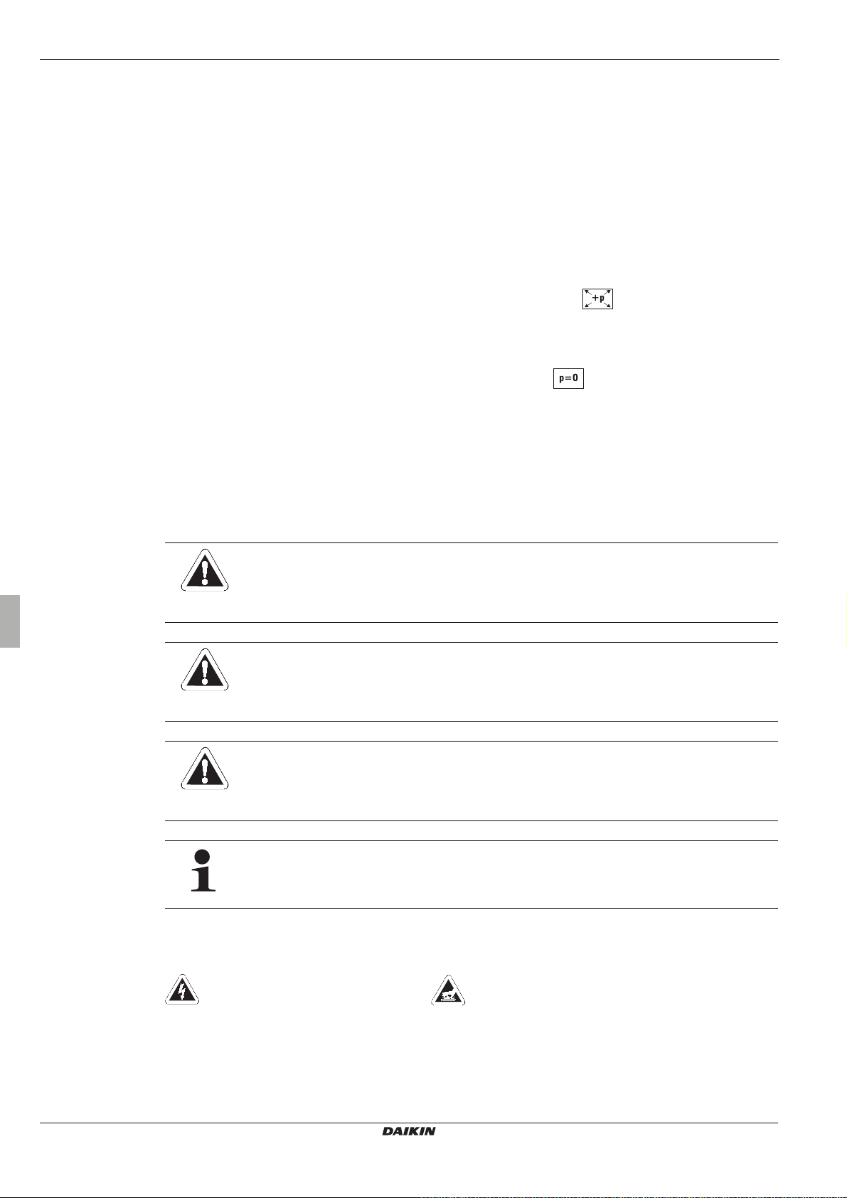
This symbol identifies user tips and particularly useful information, but not warnings or hazards.
Installation instructions
4
Special warning signs
Some types of danger are represented by special symbols:
Electrical current Danger of burning or scalding
Validity
This instructions are especially for the on-roof installation of the solar panel array, for routing the piping and for start-up.
For other types of installation (in-roof, flat roof mounting) the instructions for the individual type of installation are applicable.
Solar panels on-roof installation
EKSV26P/EKSH26P
4PW56021-1
Page 5
1 x Safety
1.3 Avoid danger
1.4 Proper use
The operating and installation instructions of the respective control and pump unit are to be observed when installing piping and starting up,
Only applicable for the unpressurized system (Drain Back) Only applicable for the pressurized system
Handling instructions
• Instructions on actions are shown as a list. Actions of which the sequential order must be maintained are numbered.
Î Results of actions are identified with an arrow.
DAIKIN solar systems are state-of-the-art and are built to meet all recognised technical requirements. However, improper use can
lead to serious injuries or death, as well as cause material damage. To avoid any danger, only install and operate DAIKIN solar
systems:
– as stipulated and in perfect condition,
– with an awareness of the safety and hazards involved.
This assumes knowledge and use of the contents of this man ual, the relevant acciden t prevention regulations and the recognised
safety-related and occupational medical rules.
.
The solar system may only be used for generating hot water and for solar-supported heating of hot water systems. The solar
system must be installed, connected and operated only according to the instructions in this manual.
Any other use outside the above-mentioned u se is considered as impro per. Any resulting damages wi ll be borne by the user/owne r
alone.
Proper use also includes observing the relevant maintenance and servicing conditions. Spare parts must at least satisfy the
technical requirements defined by the manufacturer. This is the case, forexample, with original spare parts.
1.5 Instructions for operating safety
Working on the roof
• Installation work on the roof may only be carried out by authorised and trained persons (heating technicians, roofers, etc .)
in compliance with the relevant Accident Preve ntion Regulations and with the us e of suitable personal protec tion equipment.
• Material and tools must be secured from falling down.
• Barriers must be erected to prevent persons from entering the area below the roof where the work is being carried out.
Before working on the heating system
• All work on the heating system (such as installation, conn ection, and commissio ning) may only be carried out by authorised
and trained heating technicians.
• Switch off the mains supply before starting any work on the heating s ys t em and se cu re it ag ain st un inte ntion al s witc h-o n.
Electrical installation
• Electrical installations may only be carried out by qualified e lectrical technicians under observance of the relevant electric al
guidelines and the regulations of the electric utilities company.
• Before connecting to the mains supply, ch eck that the voltage specified on the type label of the heating system
(230 V, 50 Hz) is the same as the available supply volta ge.
Instructing the user/owner
• Before you hand over the heating system, explain to the user/owner how to operate and check the heating system.
EKSV26P/EKSH26P
Solar panels on-roof installation
4PW56021-1
Installation instructions
5
Page 6
2 x Product description
2 Product description
The unpressurized system (Drain Back) can only be operated with the air-water heat pump EKHBRD*,
the pump unit EKSRPS3 and the hot water storage tank EKHWP*.
The pressurized system can only be operated with the heat pump EKHBH* or EKHBX*, the pump unit
EKSRDS1A, the control unit EKSR3PA, the solar connection set EKSOL and the hot water storage tanks
EKHWE/EKHWS.
Depending on the system, the following components are required. Unless specified otherwise, the components are not included
in the scope of delivery and need to be ordered separately.
2.1 System components for all systems
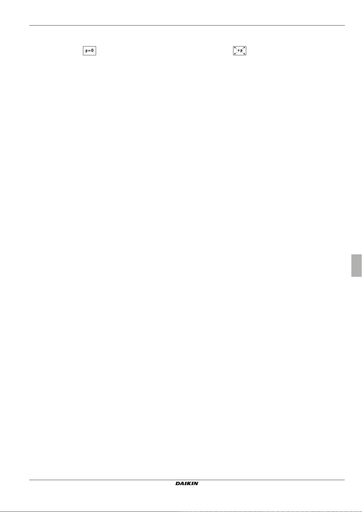
High performance flat solar panels
Solar panel EKSV26P
– H x W x T: 2000 x 1300 x 85 mm, weight: approx. 42kg
Solar panel EKSH26P
– H x W x T: 1300 x 2000 x 85 mm, weight: approx. 42kg
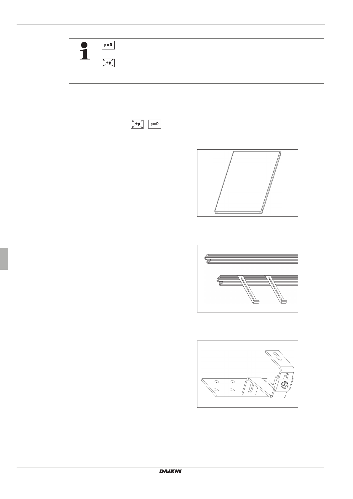
Solar panel installation rails EKSFIXMP
EKSFIXMP130
– for a EKSV26P solar panel
EKSFIXMP200
– for a EKSH26P solar panel
Consists of:
– 2 mounting profile rails
– 2 solar panel securing hooks
Kit for installing a solar panel on a roof
EKSFIXAD
Consists of:
–4x roof ties
– 8x woodscrews (Ø 8 x 60 mm)
Fig. 2-1 Flat solar panel (EKSV26P)
Fig. 2-2 EKSFIXMP
Installation instructions
6
Fig. 2-3 EKSFIXAD
Solar panels on-roof installation
EKSV26P/EKSH26P
4PW56021-1
Page 7
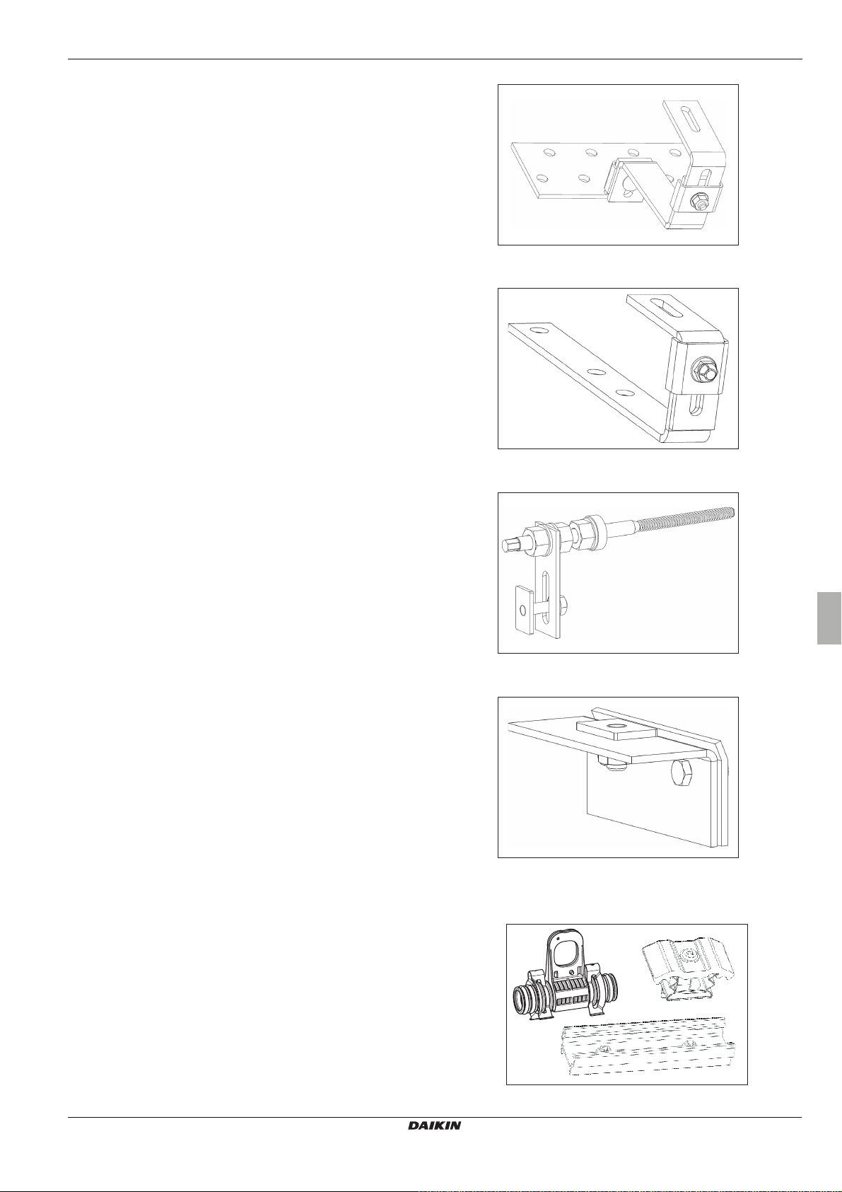
EKSFIXADP
Consists of:
– 4x roof ties (double height adjustment)
– 8x woodscrews (Ø 8 x 60 mm)
EKSFIXADS
Consists of:
– 4x roof ties for flat roofing (e. g. slate)
2 x Product description
Fig. 2-4 EKSFIXADP
EKSFIXWD
Consists of:
– 4x hanger bolt for corrugated roofing
EKSFIXBD
Consists of:
– 4x holders for welted sheet metal roofing
Fig. 2-5 EKSFIXADS
Fig. 2-6 EKSFIXWD
Fig. 2-7 EKSFIXBD
Solar panel connection
EKSFIXVBP
Consists of:
– 1x mounting profile connector
– 2x expansion joints for solar panel connection with
– 2x double clamping blocks for solar panel fixing
EKSV26P/EKSH26P
Solar panels on-roof installation
4PW56021-1
mounting support
Fig. 2-8 EKSFIXVBP
Installation instructions
7
Page 8
2 x Product description
2.2 System components for the pressurized system
Solar panel connection set
EKSRCP
Consists of:
– Assembly material for solar panel and connection pipe
(4x individual clamping blocks, 1 x equipotential bonding ter-
minal, pipe clamps),
– UV-resistant heat insulation for external area (2 m),
– Connection fittings (compression ring fittings to connect a
connecting pipe (CuØ22 mm))
– Solar panel temperature sensor
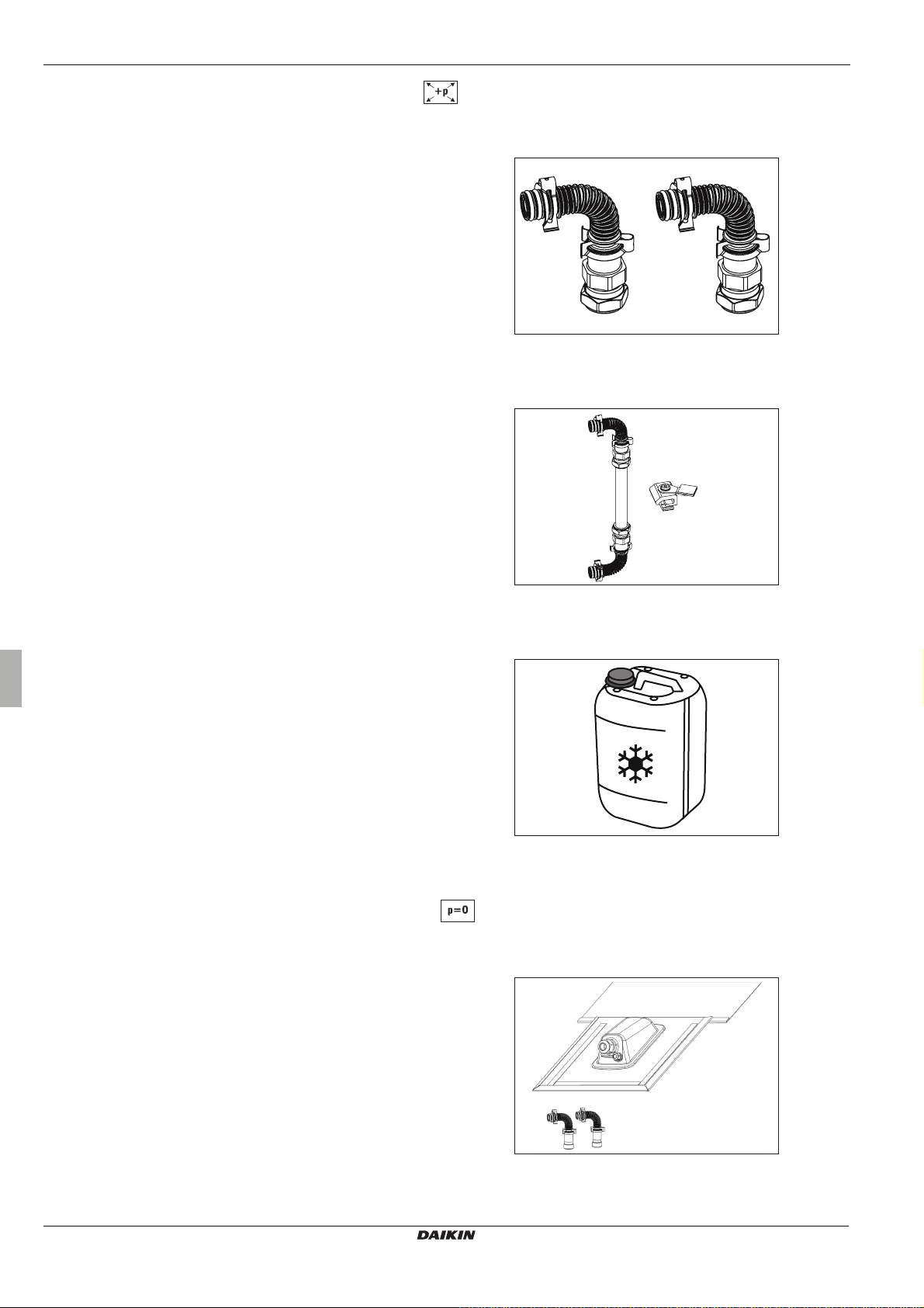
Solar panel serial connector
EKSCONLCP
For connecting two rows of solar panels one above the other.
Consists of:
– 4x individual clamping block
– 2x equipotential bonding terminal
– 2x end cap
– 2x Solar panel connection elbow with compression ring fit-
tings to connect a connecting pipe (Cu Ø22mm)
Fig. 2-9 EKSRCP
Solar liquid
EKSGFL
20 Litres of ready-mix with frost protection up to -28 °C
2.3 System components for the unpressurized system
Roof penetration kits on-roof mounting
EKSRCAP (anthracite) and EKSRCRP (tile red)
Consists of:
– Roof penetration on-roof mounting in anthracite or tile red,
– Assembly material for solar panel and connection pipe
(4x individual clamping blocks, 1x equipotential bonding ter-
minal, pipe clamps),
– UV-resistant heat insulation for external area (2 m),
– Connecting fittings (including release tool),
– Solar panel temperature sensor
Fig. 2-10 EKSCONLCP
Fig. 2-11 EKSGFL
Installation instructions
8
Fig. 2-12 EKSRCAP, EKSRCRP
Solar panels on-roof installation
EKSV26P/EKSH26P
4PW56021-1
Page 9
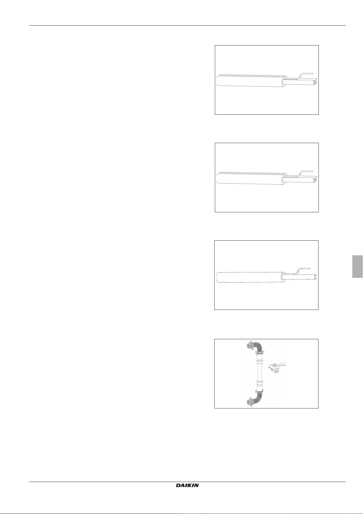
Connection pipes EKSCON
EKSCON15, L=15 m
and
EKSCON20, L=20 m
Connection pipes between solar panel array and EKSRPS3
(thermally insulated feed and return line (Al-PEX compound pip e)
with integrated sensor cable).
Extension kits for connection pipe EKSCONX
EKSCONX25, L=2.5 m
EKSCONX50, L=5 m
EKSCONX100, L=10 m
Heat insulated feed and return line with integrated sensor cable,
pipe clamps and connecting fittings.
2 x Product description
Fig. 2-13 EKSCON15 / EKSCON20
Extension kit for feed line EKSCONXV
EKSCONXV80, L=8 m
UV-resistant thermally insulated feed line with integrated sensor
cable, pipe clamps, cable connection fitting and connecting
fitting.
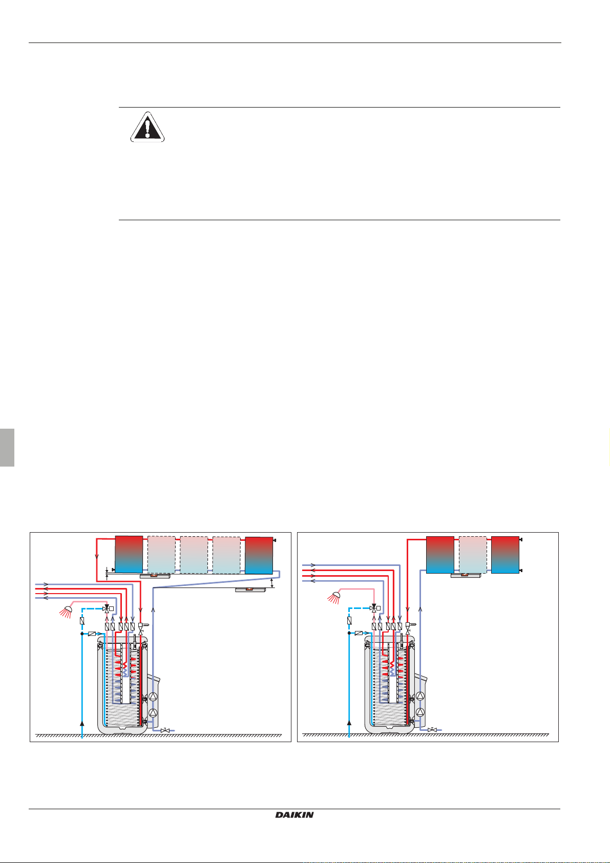
Solar panel serial connector
EKSCONRVP
For connecting two rows of solar panels one above the other.
Consists of:
– 4x individual clamping block
– 2x equipotential bonding terminal
– 2x end cap
– 2x solar panel connection elbow
– 1 m thermally insulated AI-PEX compound pipe
Fig. 2-14 EKSCONX
Fig. 2-15 EKSCONXV
EKSV26P/EKSH26P
Solar panels on-roof installation
4PW56021-1
Fig. 2-16 EKSCONRVP
Installation instructions
9
Page 10
3 x Installation
3 Installation
3.1 Transport and storage
3.1.1 Transport
The EKSV26P/EKSH26P flat solar panels are delivered wrapped in film. As long as the solar panels are secured on a pallet which
corresponds to the size of the solar panel, then industrial trucks such as forklift trucks and stackers or cranes are suitable for
transport. Other components of the solar system are supplied packaged separately.
3.1.2 Storage
The following should be taken into account when storing solar system components:
• All components should be stored in dry and frost-protected rooms only.
• Dismantled hydraulic components must be completely drained before being stored.
• Components must not be stored until they have cooled down.
• Current-carrying components must be perman ently isolated from th e power supply before storage (switc h off fuses and main
switches, remove cables) and must be secured against inadvertent restarting.
• The components must be stored in such a way that persons are not endangered by them.
CAUTION!
The EKSV26P/EKSH26P flat solar panels are impervious to slight mechanical loading. However, impact, shock
and walking on them should be avoided.
• The EKSV26P/EKSH26P flat solar panels should be transported and stored carefully in their original
packing only and this packing should not be removed until shortly before installation.
• The EKSV26P/EKSH26P flat solar panels should be stored and transported flat on even and dry supports.
– Transport with forklift trucks or cranes is only allowed if on pallets.
– Up to 10 flat solar panels can be stacked and transported on top of each other.
The regulations in the respective documentation fo r other heating c omponents apply for transport and storage of the se products.
3.2 System concepts
Solar systems are usually set up according to one of the following system layouts. This also includes the possibility of connection
on the opposite side of the flat solar panels in each case.
Connection at opposite ends possible1) (possible from 1+ solar panels) Same-side installation connection (up to maximum of 3 solar panels)
Fig. 3-1 Solar panel array connected at opposite ends with hot water storage
tank EKHWP* (1)type of connection recommended by DAIKIN)
Installation instructions
10
Fig. 3-2 Same-side connected solar panel array with hot water storage tank
EKHWP*
Solar panels on-roof installation
EKSV26P/EKSH26P
4PW56021-1
Page 11

3 x Installation
The EKSV26P/EKSH26P flat solar panels can be installed on flat roofs. Further information can be found in the
installation instructions for the solar panel flat roof support frame.
The flat solar panel EKSV26P can be integrated into the roof surface. You will find further information in the
solar panel in-roof installation instructions.
Installation instructions concerning differences between unpressurized and pressurized system
Unpressurized system (Drain Back) Pressurized system
With solar panels connected at opposite ends, the whole
solar panel array must be set up with at least 0.5%
gradient to the lower panel connection (return flow).
No particular minimum gradient of the solar panel array is
required. A gradient from the lower (return flow) connection
should however be avoided.
With a same side panel connection (max. of up to 3 solar
panels allowed) the panels must be aligned with their lower
edge precisely horizontal.
The connection pipe must be set up with a continuous gradient
of at least 2% and without any counter gradient.
Tab.3-1 Installation instructions
3.3 Laying connection pipes
3.3.1 Unpressurized System
The connection pipe between the solar panel array and the hot
water storage tank must be made of pressure-resistant metal
piping (recommended Cu Ø22 mm). Using plastic piping is not
allowed.
CAUTION!
Siphon action may never be allowed to occur anywhere in the pipe run between storage cylinder and the flat
solar panel. This could lead to functional faults and even material damage.
• Always make sure that pipe runs have a continuous gradient of at least 2%.
CAUTION!
In the case of longer pipe runs with only a minimum gradient, it is possible for water pockets to develop due
to thermal expansion of the plastic pipes between the mounting points with siphon action:
• The pipes should either be fixed to a rigid auxiliary structure (e.g. a profi le rail, pipe etc.) or the pipe should
be run alongside a drainage pipe having a gradient (e.g. HT pipe).
• Lay prefabricated connection pipes (fee d and return flow) with integrated sen sor cable (see Chapter2 "Product description“)
Tab.3-2 Maximum lengths of the DAIKIN connection pipes
EKSV26P/EKSH26P
Solar panels on-roof installation
4PW56021-1
between the planned installation site of the solar panel array in the inner roof and the installation site of the hot water
storage tank with the EKSRPS3 pump unit.
– Make sure there is adequate length for connection to the hot water storage tank and the flat solar panels.
– The maximum permissible overall pipe length must not be exceeded (see Tab.3-2).
Number of solar panels Max. possible total
length of pipe
245m
330m
417m
515m
If larger distances need to be covered, c alculations
need to be made for the dimensioning of the connecting pipes.
Contact DAIKIN Service.
Installation instructions
11
Page 12

3 x Installation
Additional notes about connecting pipes
If on-site conditions make it impossible or very d ifficult to install the connecting pipe s in the manner described above, slig ht deviations from the specified installation are permitted. Hereby, the inflow pipe may not be larger than 18x 1 mm.
1. If vertical copper pipes are already installed in the house, they c an be used if a continuous connection pipe gradient can be
guaranteed.
2. If a uniform gradient from the second roof penetration to all pipe sections can not be gua ranteed whe n the solar pa nels are
connected at opposite ends, then for roof penetration purposes , the inflow pipe can be connected to the top of (e.g. through
a ventilating tile), if:
– the highest point if the inflow pipe is not more than 12 m above the storage cylinder mounting floor level,
– the internal diameter of the inflow pipe is not more than 13mm,.
– a continuous rise of the inflow pipe to the highest point, as well as a continuous gradient to the storage cylinder is
ensured.
3. For pipe runs in which only a limited gradient can be achieved, copper pip e s ho uld be us ed on site. This avoids the need for
a rigid supporting structure, and prevents the formation of water pockets due to expansion of the plastic pipes.
3.3.2 Pressurized system
The connection pipe between the solar panel array and the hot water storage tank must be made of pressure-resistant metal
piping (recommended Cu Ø22 mm). Using plastic piping is not allowed.
For the roof penetration DAIKIN recommends laying the connection pipes through ventilation tiles to the inside of the roof.
Installation instructions
12
Solar panels on-roof installation
EKSV26P/EKSH26P
4PW56021-1
Page 13

3.4 Installing the solar panel components
DANGER!
There is an increased accident risk during work on a roof.
• Installation work on the roof may only be carried out by authorised and trained persons (heating technicians, roofers, etc.) in compliance with the relevant Accident Preve ntion Regulations and with the use of
suitable personal protection equipment.
• Material and tools must be secured against falling down.
• Barriers must be erected to prevent persons from entering the area below the roof where the work is
being carried out.
• Before starting the installation work, ch eck that the roof structure has adequate carry ing c apa city and
is undamaged. (e.g. defective laths or leaks in the roof.).
WARNING!
After their packaging is removed, the flat solar panels will become hot very qu ickly if they are exposed to the
sun's rays.
• Wear protective gloves.
• Remove protective caps (not heat-resistant) after positioning the flat solar panel.
• Do not remove the protective covering of the glass on the solar panel until leak testing has been
completed.
3 x Installation
CAUTION!
Frost or overheating can damage the system.
• Permit the system to drain. Make sure that th e flat s olar p anels a re i nstalle d so that thei r lowe r edge is
always higher than the inflow coupling of the Solaris storage cylinder.
Unless specified otherwise, the installation steps quoted for tiled roofs are the same for other roof coverings.
Notes for safe and trouble-free operation
• Mount the solar panel array with a gradient to the lower collector coupling (return flow).
• For flat solar panel arrays with connections on same side (up to 3 solar panels permitted), the lower edges of all the solar
panels must be absolutely horizontal. However, we recommend always making the connections at opposite ends.
• Always run the connection pipe between the flat solar pan els and the s torage with contin uous gap to avoid a s iphon effe ct
(two-way gap) over the whole connection passage.
• The upper edge of the flat solar panels may not be more than 12m above the storage cylinder(s) mounting floor level.
3.4.1 Installing the supporting structure for subsequent installation on the roof
DANGER:
Non-intended use and prohibited modifications to the structure reduc e safety. Any change to the struc ture of
components is not permitted.
EKSV26P/EKSH26P
Solar panels on-roof installation
4PW56021-1
Installation kits for on-roof installation, we offer the roof bracket EKSFIXAD and EKSFIXADP for roof tiles, for
slate roofs the roof bracket EKSFIXADS, for corrugated roof coverings the roof bracket EKSFIXWD and for
welted sheet metal coverings the roof bracket EKSFIXBD.
Installation instructions
13
Page 14

3 x Installation
Main dimensions of solar panel array for on-roof mounting
Number of solar panels 1 2 3 4 5
Measuring point Dim. Dimensions in mm
Solar panel array width (length mounting profile rail)
Distance from roof breakthrough H
Height of solar panel array
Distance from bottom edge of solar panel to lower
mounting profile rail
Spacing of the mounting rails
Distance from lower solar panel edge to lower edge of
the perforated plate of roof mounting bracket
Max. distance from edge of solar panel a rray to the first
roof mounting bracket
Spacing of the roof mounting brackets of a flat solar
panel
Spacing of roof mounting brackets between two flat
solar panels
Distance between solar panel array and the first solar
panel securing clip
Spacing of the roof mounting brackets of a flat solar
panel
Spacing of solar panel mounting brackets between two
flat solar panels
Distance of edge of solar panel to hydraulic connection E
Centre-to-centre distance of the solar panel couplings
Distance from top edge of solar panel to connection of
solar panel sensor
Tab. 3-3 Main dimensions of a solar panel array for on-roof mounting
EKSV26P B 1332 2664 3996 5328 6660
EKSH26P 2032 4064 6096 8128 10160
300 to 700
2000
EKSV26P H
0
1
EKSH26P 1300
EKSV26P Y
Y
0
1
200
1400 to 1600
EKSH26P 800 to 1000
EKSV26P X
Y
2
X
0
1
235 to 270
400
500 to 1100
EKSH26P 1000 to 1800
X2 230 to 630
120 to 220
900 to 1100
EKSV26P A
A
0
1
EKSH26P 1600 to 1800
EKSV26P E
A
2
0
1
240 to 440
approx. 73
1854
EKSH26P 1154
F 172
Fig. 3-3 Main dimensions of a solar panel array for on-roof mounting (example shows solar panel EKSV26P)
1 Roof mounting bracket
2 Mounting rail
3 Solar panel securing clip
4 Flat solar panel EKSV26P
Installation instructions
14
5 Return flow connection
6 Flow connection
7 Solar panel sealing plug
8 Solar panel connection elbow
9
(ventilation tiles)
Universal roof penetration
Roof penetration exists on site
Solar panels on-roof installation
EKSV26P/EKSH26P
4PW56021-1
Page 15

3 x Installation
Roof tile Roof slate
Fig. 3-4 Side view of a solar panel installed on the roof
α Inclination angle (permissible from 15° to 80°) T3 Height adjustment range of the on-roof securing tie:
T1 Solar panel height = 85 mm EKSFIXAD:
T2 Height of mounting profile rail =37 mm
EKSFIXADP:
EKSFIXADS:
141 to 178 mm
131 to 173 mm
78 to 108 mm
Installing the roof brackets and mounting rails
A defined roof area is required per flat solar panel.
– for the V26P: 2.0 x 1.33m
– and for the H26P: 1.30 x 2.03m
The main dimensions of the solar panel array (as shown in Fig3-3 and Fig 3-4) are summarised in Tab. 3-3.
Required tool:
– 13 mm hex soc ket and socket wrench
– Hex socket wrench SW5.0
– 13 mm open-ended spanner
– Hammer
1. Measure the solar panel array and mark the installation site.
2. Remove the row of tiles above the intended lower edge of the flat solar panels.
2
,
2
,
– Cut-off grinder with diamond cutting wheel
–Spirit level
– Meter ruler
– Cordless drill with 6mm bit
3. Position the mounting rail horizontally centred on the rafters (for the entire width of the solar panel array). If several
EKSV26P/EKSH26P
Solar panels on-roof installation
4PW56021-1
mounting rails are required for an array, they must first be joined using the mo unting rail connector from the ADS FIXVBP kit
and the pre-mounted studs.
Installation instructions
15
Page 16

3 x Installation
4. Determine the installation points for the on-roof mounting ties. The on-roof mounting tie s should be distributed even ly under
the mounting profile rail (Fig3-5 and Fig 3-6).
WARNING!
Insufficiently dimensioned supporting structures ca n endanger persons, the building, and the solar installation.
•Also note the dimensions X
, X1, and X2 given in Tab.3-3 for the rafter spacing – if necessary, a
0
suitable supporting structure will have to be provided.
• Check the load bearing capacity of the supporting structure. Do not use roofing battens.
Fig. 3-5 Aligning the on-roof ties from the
planned lower edge of the solar
panels at distance Y
2
Fig. 3-6 Determining the mounting
positions of the roof brackets
Fig. 3-7 Attach the roof brackets to the
rafters with at least two screws
5. Position the perforated plate of the roof mounting bracket so that at least two screw holes are located over the rafter.
6. Place the mounting rail on the perforated plates, and align the mounting brackets parallel to the roof tiles or roof slates.
7. Roof tile:
– Fix each on-roof tie (EKSFIXAD, EKSFIXADP) to the rafters with at least two of the woodscrews provided (Fig 3-7), using
a Ø 6 mm drill to produce a pilot hole.
Roof slate:
– Prepare a covering plate Fig3-4 (taking care with adequate dimensioning).
– Fix the covering plate and on-roof ties (EKSFIXADS) to the rafters with screws.
– The heads of the screws should be sealed with a suitable silicon compound to prevent the ingress of water.
The mounting brackets may neither press on the roof tiles below, nor raise the roof tiles above.
8. If several mounting rails are being used:
• Release a stud on the assembly profile connector (do not remove) and separate the assembly profile rails again.
9. Push the individual mounting rails into the pre-assembled slide blocks of the roof mounting bracket from the side.
Installation instructions
16
10. If several mounting rails are being used:
• Rejoin the rails and fix together finally using the studs supplied.
11. Tighten the self-locking nuts with which the slide blocks have been attached to the roof mounting brackets. Take care to
align the mounting rail parallel to the edges of the roof tiles (Fig3-8 to Fig 3-9).
Solar panels on-roof installation
EKSV26P/EKSH26P
4PW56021-1
Page 17

3 x Installation
12. Adjust the height of the mounting profile rail (Fig3-10 to Fig3-11).
– With connections on both sides (always recommended), align the mounting profile rail with a slight gradient to the
return flow connection (water feed to the lower solar panel connection). A negative gradient should be avoided at all
costs.
– With same-side connection (up to 3 solar panels) the mounting prof ile rail must be aligned exactly horizontally. How-
ever, we recommend always placing the connection on opposite sides (ensures automatic venting of the solar panel or
draining of the solar panels in the event of a pump standstill).
Fig. 3-8 Securely screw the profiles on the
on-roof tie top section
Fig. 3-11 After connection, align the profiles
horizontally or with a slight gradient
Fig. 3-9 Align the profiles parallel to the
roof tile edge
Fig. 3-10 Height adjustment of th e mounting
bracket
13. Replace the row of roof tiles.
14. Mark the transition points of the roof ties on the roof tiles (Fig3-12).
15. Knock out the lower tile webs at the marked transition points for the mounting brackets, or remove them with the tile cutter
(Fig 3-13).
16. Install the upper mounting profile rail at a distance of Y
EKSV26P/EKSH26P
Solar panels on-roof installation
4PW56021-1
Fig. 3-12 Mark the position of the on-roof
tie
Fig. 3-13 Mark the transition points of the
roof ties on the roof tiles and
remove the tile webs
from the lower mounting profile rail (Fig 3-14) (mounting sequence
1
Fig. 3-14 Mounting the upper rails
(see Tab. 3-3 for dimension)
the same as the lower mounting profile rail). Make sure that the upper mounting profile rail forms a flat parallel area for
supporting the flat solar panels in connection with the lower mounting profile rail and the height adjustment.
Installation instructions
17
Page 18

3 x Installation
CAUTION!
In order to prevent torsional stresses and fixing difficulties when mounting the solar panels;
• only slightly tighten the self-locking nuts of the sliding blocks and the height adjustment in the upper
mounting profile rail,
• align both mounting profile rails of the first flat solar panel exactly to each other, and then
• tighten the self-locking nuts.
3.4.2 Installing the supporting structure for subsequent installation on a flat roof
Further information is included in the operating instructions "Flat-roo f mounting of solar panels". It is supplied with the b as ic flat
roof support frame package.
3.4.3 Installing the supporting structure for subsequent in-roof installation
Further information is included in the operating instructions "In-roof mounting of solar panels". It is supplied with the basic inroof mounting package.
3.4.4 Installing the first flat solarpanel
1. Fit solar panel securing ties vertical to the solar panel support surface, at the distance specified for the type of solar pane l
into the guiding groove of the lower mounting profile and tilt downwards. After they have been hooked on, the solar panel
securing clips can be moved sideways (see Fig 3-15 and Fig 3-16).
2. Lift the flat solar panel onto the roof area using a crane. If no crane is available, the solar panel can be hoisted onto the roof
with a rope, using a ladder leaning against the roof edge. Depe nding on the installation re quirements, unpack the sol ar panel
before or after the transport to the roof and remove the collection pipe protective plugs.
WARNING!
Danger of burns from hot solar panel couplings and hot solar panel frame.
• Do not touch hot parts.
• Wear protective gloves.
The flat solar panel must be lifted onto the roof i n th e co rrect o rien tation fo r mounting ( preve nts faul ts during
connection or difficult manoeuvring operations). The top side of the solar panel is marked on the protective
cover of the solar panel glazing. The plugs for the solar panel temperature sensor and the round solar panel
connection seals must at the top when aligning the flat solar panel.
3. Position the flat solar panel above the mounting rails as shown in Fig3-17, and carefully lower it into the securing hooks.
Installation instructions
18
Fig. 3-15 Inserting the solar panel securing
clips
Fig. 3-16 Positioning the solar panel
securing clips
Fig. 3-17 Lowering and aligning the flat
solar panel
4. Move the flat solar panel sideways until the left-hand outer ends of the two mounting rails project approx. 25mm beyond
the solar panel's edge (Fig3-18).
Slide the individual clamping block sideways into the mounting profile rail (flush to the end) and screw down tightly using
an Allen key (Fig 3-18).
Solar panels on-roof installation
EKSV26P/EKSH26P
4PW56021-1
Page 19

3 x Installation
5. Push the single clip equipotential bonding terminal at the return flow connection into the mounting profile and tighten using
an Allen key (Fig 3-19).
6. Slide the individual clamping block onto the mounting rail and tighten using an Allen key.
Fig. 3-18 Check correct mounting position,
slide the individual clamping block
into the mounting profile and
screw down tightly
Fig. 3-19 Slide the individual clamping block
with equipotential bonding
terminal in and screw down tightly
3.4.5 Installing the other flat solar panels
1. Insert the double clamping blocks in the upper and lower mounting profile rail, push down with the Allen key placed on the
bolt and turn it clockwise by approx. 45° (so that the bottom clamping profile moves to the clamping position) (Fig3-20).
2. Check th e position of the bottom clamping profile (Fig 3-21).
3. Slide the double clamping blocks onto the last mounted flat solar panel until the clamping profile clicks into place into the
solar panel profile (Fig3-22).
Fig. 3-20 Inserting double clamping block Fig. 3-21 Check the position of the bottom
4. Apply lubricant to the O-rings of the expansion joints (Fig3-23).
5. Insert the expansion joints in the connection pipes of the last mounted solar panel until the retaining clamps click in place
6. Lift the next flat solar panel onto the mounting rails (see Section 3.4.4, step 2), and lower into the securing clips at a distance
EKSV26P/EKSH26P
Solar panels on-roof installation
4PW56021-1
CAUTION!
Careless handling can damage the components, resulting in difficulties during installation.
• Never crush or squash the expansion joints on the solar panel connections.
• Check connection pipes of the flat solar panels for burrs and de-burr if necessary.
(Fig 3-24).
from the expansion joints (Fig3-25).
clamping profile .
Fig. 3-22 Positioning of the double clamping
block
Installation instructions
19
Page 20

3 x Installation
Fig. 3-23 Inserting the expansion joint Fig. 3-24 Clicking the expansion joint in
position
Fig. 3-25 Positioning the next flat solar
panel
7. Carefully slide the next flat solar panel up to the last mounted flat solar panel. Make sure that the expansion joints slide
cleanly into the connection pipes of the flat solar panel.
8. Slide the next flat solar panel further up to the stop against the last mounted flat solar panel (Fig3-26). You should be able
to hear the retaining clamps click in place. The distance between the flat solar panels is determined automatically by the
length of the expansion joints with mounting supports fitted.
CAUTION!
If the retaining brackets do not click in place audibly, the solar system can develop leaks and thus restrict
operational safety.
Reasons for the retaining clamps not engaging:
– Flat solar panels not completely pushed up together.
– Absorber position moved (push the absorber into the conne ctions on the oppo site sid e in the correct pos i-
tion, wearing protective gloves).
CAUTION!
If the connections on the flat solarpanel (EKSFIXVBP) are not fitted with extreme caution, the seal ring can
get damaged. This causes leaks in the system.
• Always fit the expansion joints to the flat solar panels with extreme caution.
• Bring the next flat solar panel in alignment with the connection pipes of the previo us flat solar panel when
pushing together.
Installation instructions
20
9. Tighten down the double clamping blocks (Fig3-27).
10. Pull off the assembly supports (Fig3-27).
11. Insert the individual clamping blocks for the last flat solar panel and tighten down (Fig3-28).
Fig. 3-26 Sliding the flat solar panels
together
Fig. 3-27 Pulling off the assembly supports . Fig. 3-28 Insert the individual clamping
blocks for the last flat solar panel
and tighten down .
Solar panels on-roof installation
EKSV26P/EKSH26P
4PW56021-1
Page 21

3 x Installation
3.4.6 Hydraulic connection of the flat solar panel (unpressurized system)
CAUTION!
Thermal expansion of the plastic pipes in the connection pipe over extended horizontal sections with only a
slight gradient can lead to the formation of pools of water.
Pools of water between the fixing points prevent draining of the system. This me ans frost safety is no longer
ensured.
• The pipes should either be fixed to a rigid auxiliary structure (e.g. a profile rail, pipe etc.,) of the pipe
should be run alongside a drainage pipe having a gradient (e.g. HT pipe).
CAUTION!
Siphon action may never be allowed to occur anywhere in the pipe run betwe en storag e cylind er and the flat
solar panel. This could lead to functional faults and even material damage.
• Always make sure that pipe runs have a continuous gradient of at least 2%.
If the connecting pipe of EKSCON15 or EKSCON20 is not long enough to bridge the distance between the storage cylinder and
the solar panel array, it can be lengthened depending on the size of the solar panel array.
Extension kits EKSCONX25 (2.5 m), EKSCONX50 (5m) and EKSCONX100 (10m) are available.
Take account of the instructions concerning lengths of pipe in Tab.3-2, Page11.
Instructions on pipe installation
1. Run the connecting pipe with a continuous gradient between the flat solar panels and the storage cylinder.
2. Connect the solar panel array at opposite ends and set it up so that the return flow coupling (at the bottom) is located at
the lowest point of the solar panel array (installation layouts Chapter 3.2Page10).
The different connection points and dimensions of the inflow connection pipe (at the top of the solar panel
Ø 15 mm) and the return flow connection pipe (at the bottom of the solar panel Ø18 mm) make it impossible
to confuse one pipe with the other.
• However, you must ensure that the infl ow and return flow pipes on the flat solar panel are lab elled as heat
generators.
3. Remove three roof tiles at each intended roof penetration point (one or two tile rows be low the solar panel connec tion pipes).
4. Lay the connection pipes up to the roof penetration and fix in position (e.g. with clamps).
5. Carefully open the thermal roof insulation under the penetration point, so that the return flow pipe (Ø18 mm) can be pulled
out and can be laid with sufficient gradient to the roof penetration.
CAUTION!
Leaking vapour barriers can lead to building damage.
• Reseal the vapour barrier from the inside at the penetration points of the connecting pipes and cable.
6. Run the connecting pipes through the roof at the points provided. To ensure uninterrupted thermal insulation (also within
7. Remove the thermal insulating hoses of the connecting pipes so that the pipes can be passed through the individual roof
EKSV26P/EKSH26P
Solar panels on-roof installation
4PW56021-1
CAUTION!
If plastic pipes are damaged, there is a risk that they will break.
• When cutting through the thermal insulation, never damage the outer surface of the VA Solar pipes.
the roof structure), the insulation must be resealed at the penetration points (e.g. with adhesive tape).
penetrations (Fig3-29).
Installation instructions
21
Page 22

3 x Installation
8. Pull the inflow pipe (at the top of the solar panel Ø 15 mm) and the return flow pipe (at the bottom of the solar panel
Ø 18 mm) through the M32 screw connection of the respective roof penetratio n point. Next, push the equi potential bonding
cable and the solar panel temperature sensor cable through the respective M16 glands from inside (Fig3-30).
9. Cover the roof penetrations (Fig 3-31).
– The roof tiles at the side and above must overlap the roof penetration.
– The corrugated flashing must overlap the roof tile underneath and be shaped to match the roof tile.
CAUTION!
With special roof coverings, such as roof ti les with very pron ounced u ndulations (large differ ences in height),
sealing problems can occur with the universal roof penetration box.
• In such cases, and also with plane tiles or slate roofing, a professional roofer should be consulted.
Fig. 3-29 Work step 7 Fig. 3-30 Work step 8 Fig. 3-31 Work step 9
10. Tighten the ring nuts of the glands for the pipes and cables (see Fig3-32).
11. Bend the connecting pipes as necessary, mark the required length (Fig3-33), and cut off (Fig 3-34).
Fig. 3-32 Work step 10 Fig. 3-33 Work step 11- marking out Fig. 3-34 Work step 11- cutting off
12. De-burr the ends of the pipes (O-ring protection in push fitting).
13. Cut the enclosed UV resistant heat insulation pipes to the required length (Fig3-35).
14. Slide the heat insulation tubes over the solar pipe and clinch (Fig3-36).
15. Push the plug fittings of the solar panel connection elbows onto feed (at the top of the solar panel Ø15 mm) or return flow
connection pipe (at the bottom on the solar panel Ø 18 mm) respectively (Fig3-37).
Installation instructions
22
Solar panels on-roof installation
EKSV26P/EKSH26P
4PW56021-1
Page 23

3 x Installation
Fig. 3-35 Work step 13 Fig. 3-36 Work step 14 Fig. 3-37 Insert push fittings solar panel
connection elbows
16. Apply lubricant to the O-rings of the solar panel connection elbows . Insert solar panel connec tion elbows into the solar panel
connection pipes until the retaining clamps click in place (Fig3-38).
17. Slide the clinched thermal insulation hose over the fitting (Fig3-39).
18. Apply lubricant to the O-rings of the end plugs. Insert the end plugs into the open solar panel connection pipes until the
retaining clamps click in place. (Fig3-40).
Fig. 3-38 Work step 16 Fig. 3-39 Work step 17 Fig. 3-40 Work step 18
3.4.7 Hydraulic connection of a flat solar panel (pressurized system)
WARNING!
Danger of burns from hot solar panel couplings and hot solar panel frame.
• Do not remove the cover of the solar panel until hydraulic connection work has been completed.
• Do not touch hot parts.
• Wear protective gloves.
CAUTION!
Danger of being scalded if you use the wrong connection pipes.
• The connection pipe between the solar panel array and the hot water storage tank must be made of
pressure-resistant metal piping (recommended Cu Ø22 mm).
• Using plastic piping is not allowed.
The connection fittings include d in the connection kit EKSRCP have compression ring joints for copp er piping Ø22 mm. Therefore
we recommend also using copper piping with a Ø22 mm as the connection pipe between the solar panel array and the h ot water
storage tank.
Commercially available ventilation tiles for roofing are suitable for the connection pipes penetrating the roof.
EKSV26P/EKSH26P
Solar panels on-roof installation
4PW56021-1
Installation instructions
23
Page 24

3 x Installation
Instructions on pipe installation
1. Lay connection pipes between the flat solar panels and the location of the hot water storage tank.
– Connect the solar panel array at opposite ends and set it up so that the return flow coupling at the bottom is located at
the lowest point of the solar panel array (installation layouts Chapter 3.2 Page10). The feed pipe should preferentially
be connected at the opposite end at the top of the solar panel.
– Don't forget to thermally insulate the connection pipes indoors.
2. Install connection fittings (Fig 3-41).
3. Outdoors cover the connection pipes with UV resistant thermal insulation tubing.
4. Apply lubricant to the O-rings of the end plugs. Insert end plugs into the open solar panel co nnection pipes until the retainin g
clamps click in place (Fig 3-42).
CAUTION!
Leaking vapour barriers can lead to building damage.
• Reseal the vapour barrier from the inside at the penetration points of the connecting pipes and cable.
5. Connect the connection pipes (Cu Ø22 mm) to the compression joints of the connection fittings (Fig 3-43).
Fig. 3-41 Work step 2 Fig. 3-42 Work step 4 Fig. 3-43 Work step 5
3.4.8 Installing the equipotential bonding
WARNING!
The equipotential bonding terminal is not a substitute for a lightning rod. It is merely intended to protect the
solar panel temperature sensor. Local lightning strike regulations must be observed.
1. Release the slotted screws on the
equipotential bonding terminal
(Fig 3-44).
2. Connect the equipotential bonding
cable (not included in delivery).
3. Tighten the screws of the
equipotential bonding terminal
Fig 3-45).
Fig. 3-44 Clamping plate with equipotential
bonding terminal
4. Lay the equipotential bonding cable to the equipotential bonding rail, fix with ca ble ties and connect to the eq uipotential bus
bar.
Fig. 3-45 Connecting equipotential bonding
cable
Installation instructions
24
Solar panels on-roof installation
EKSV26P/EKSH26P
4PW56021-1
Page 25

3 x Installation
If two or more solar panel rows are installed, they must be connected using an equipotential bus bar. Equipotential terminals are:
– included in the EKSCONRVP kit and
– in the EKSCONLCP kit.
3.4.9 Installing the solar panel temperature sensor
CAUTION!
Connection pipes will not dissipate voltages induced by electrical storms. Under adverse circumstan ces, these
voltages can extend through the solar panel sensor up to the control and thus damage both.
• Generate equipotential bonding ("Earthing") between foundation and solar panel array.
This should only be performed by an authorised special ist (electrician) in accordance with the local regulations.
The mounting openings for the solar pan el temperature sensor are located to the le ft a nd righ t at the top of the side solar panel
frame, approx. 10 cm below the upper connection. The mounting openings ar e fitted with plugs in the a s-delivered condition. Fi t
the solar panel temperature sensor at the position where the feed pipe is connected.
1. Remove the sensor plugs (Fig 3-46).
2. Push solar panel temperature sensor up to the stop in the flat solar panel (Fig3-47). The sensor must be clamped to the
absorber plate.
3. Run the silicone-covered sensor cable to the roof penetration box (with drip-off elbow), and secure it to the mounting rail or
connecting pipe by means of cable ties (Fig3-48).
CAUTION!
Moisture can damage the temperature sensor.
• When securing the cable, make sure that no rainwater can run down the cable to the sensor.
Fig. 3-46 Work step 1 Fig. 3-47 Work step 2 Fig. 3-48 Work step 3
4. Inside the roof, connect the silicon cable of the solar panel temperature sensor to the feed cable of the solar panel
EKSV26P/EKSH26P
Solar panels on-roof installation
4PW56021-1
temperature sensor from the pump unit ( EKSRPS3 or EKSR3PA)
Installation instructions
25
Page 26

3 x Installation
3.4.10 Removing the flat solar panel
WARNING!
Live parts can cause an electric shock on contact and cause life-threatening burns and injuries.
• Before beginning removal work on live parts or the solar control system, disconnect them fro m the power
supply (switch off fuse, main switch) and secure against unintentional restart.
• Comply with the relevant safety at work regulations.
WARNING!
Danger of burns from hot solar panel couplings and hot solar panel frame.
• Do not touch hot parts.
• Wear protective gloves.
Solar panel dismantling is carried out basically in the reverse sequence to the solar panel assembly.
If the flat solar panels are to be separate d,
the connection elbows or expansion joints
must first be released as follows:
1. Press the retaining clamps out of the
engagement positions and pull off
(Fig 3-49 and Fig 3-50).
2. Pull off the connection elbows
(Fig 3-50).
Fig. 3-49 Work step 1 Fig. 3-50 Work step 2
Installation instructions
26
Solar panels on-roof installation
EKSV26P/EKSH26P
4PW56021-1
Page 27

4 Start-up and taking out of service
4.1 Start-up
The instructions for integrating the hydraulic system, start-up, operating the control systems and rectifying faults and malfunctions are contained in the operating and installation instructions of the control system and pump unit ( EKSRPS3 or
EKSR3PA + EKSRDS1A).
4.2 Taking out of service
4.2.1 Temporary shutdown
If solar heating support is not required for water heat ing for an extended period, the so lar system can be switched off tempora rily
at the mains switch of the solar control system.
If there is a danger of frost:
– the solar system must be started up again
or
– suitable antifreeze measures must be applied to the co nnected heating system and hot water storage tank (e.g. draining ).
4 x Start-up and taking out of service
CAUTION!
A heating system which is shut down can freeze in the event of frost and may suffer damage.
• Drain the heating system that is shut down if there is danger of frost.
If there is a danger of frost for just a few days , the unit's excellent h eat insulation means that the water storage
tank does not have to be drained, provi ded that the storage tank temperature is monitored regularly and does not
fall below+3°C. This does not, however, provide any protection against frost for the connected heat distribution system!
Draining the storage tank
• Switch off the main switch and secure against restarting.
•:
– Connect a hose to the solar return flow with the boiler filling and draining valve using the hose connection.
– Drain the tank's water content.
•:
– Follow the instructions on shutdown prov ided in the operating and installation instructions EKSR3PA + EKSRDS1A.
Recommendations for disposal
The DAIKIN solar system is constructed in an environme ntally friendly way. During the disposal proces s, the only waste produced
is that which can be used for material or thermal recycling.
The materials that are suitable for recycling can be separated so that they are unmixed.
Through the environmentally friendly de sign of the solar system, DAIKIN has compl ied with requirements for environmentally sound disposal. Proper disposal in complian ce with the applicable national regulations of the country
of use is the responsibility of the user/owner.
EKSV26P/EKSH26P
Solar panels on-roof installation
4PW56021-1
Installation instructions
27
Page 28

5 x Technical data
5 Technical data
5.1 Basic data
Dimensions L x W x H 2000 x 1300 x 85 cm 1300 x 2000 x 85cm
Gross surface area 2.60 m2 2.60 m2
Aperture surface area 2.35 m2 2.35 m2
Absorber surface area 2.36m
Absorber
Coating MIRO-THERM (absorption max. 96%, emission approx. 5%
High-performance flat solar panel EKSV26P EKSH26P
Basic data
2
2.36 m
Harp-shaped copper tube register with welded -on hi ghly selective coated alumini-
um sheet.
2
± 2%)
Glazing Single pane safety glass, Transmission approx. 92 %
Heat insulation Rock wool (50mm)
Weight 42 kg 42 kg
Water content 1.7 l 2.1 l
Max. pressure drop at 100l/h 3.0 mbar. 0.5 mbar.
Possible inclination angle on-roof 15° to 80°
Max. standstill temperature approx. 200°C
Max. operating pressure 6 bar
The solar panel is permanently standstill proof and thermo-shock tested.
Minimum solar panel yield above 525kWh/m
Tab. 5-1 Technical Data Flat Solar Panel
2
per year with 40% cloud coverage (location Würzburg)
EKSV26P
EKSH26P
Installation instructions
28
Fig. 5-1 Hydraulic resistance flat solar panels
Solar panels on-roof installation
EKSV26P/EKSH26P
4PW56021-1
Page 29

5.2 Wind zones
5 x Technical data
5.2.1 Subdivision into areas
Wind speed at
Wind zone Area
1 Inland 102 km/h 116 km/h 125 km/h
2 Inland 116 km/h 129 km/h 137 km/h
Coast 133 km/h 144km/h 15 km/h
3 Inland 129 km/h 140 km/h 151 km/h
Coast 148 km/h 158km/h 164 km/h
4 Inland 140 km/h 154 km/h 164 km/h
Coast 161 km/h 170km/h 179 km/h
Tab.5-2 Wind zone sub-division
5.2.2 Maximum permissible building heights
Location Wind zone 1 and 2 Wind zone 3 Wind zone 4
Inland 25m 25 m 25m 18 m 25m
Building height 10 m Building height 18 m Building height 15 m
Maximum permissible building heights for flat solar panel installation
Min. number of roof ties per
Tab. 5-3 Max. permissible building heights for flat solar panels for on-roof installation
5.3 Snow load zones
Tab. 5-4 Max. permissible snow loads for flat solar panels for on-roof installation
Coast 25m 10m 25m — 10m
flat solar panel
4 4 6 4 6
Snow load Snow load zone Maximum permissible altitude for flat solar panel
installation
1 448 m 507m
<0.65 kN/m²
1a 400 m 418m
2 not permissible 286m
<0.85 kN/m²
2a not permissible
<1.10 kN/m² 3 not permissible
Min. number of roof ties per flat solar panel 4 6
EKSV26P/EKSH26P
Solar panels on-roof installation
4PW56021-1
Installation instructions
29
Page 30

6 x List of keywords
D
Danger of frost . . . . . . . . . . . . . . . . . . . . . . . . . . . . . . . . . . . . . .28
Dimensions of solar panel array
. . . . . . . . . . . . . . . . . . . . . . . . . .14
E
Equipotential bonding . . . . . . . . . . . . . . . . . . . . . . . . . . . . . . . . . .25
Explanation of symbols
. . . . . . . . . . . . . . . . . . . . . . . . . . . . . . . . .4
F
Flat roof mounting . . . . . . . . . . . . . . . . . . . . . . . . . . . . . . . . . . . .19
H
High performing flat solar panels . . . . . . . . . . . . . . . . . . . . . . . . . .6
Hydraulic resistance
Permissible snow load zones
Technical data
Hydraulic connection
Pressurized system
Unpressurized system
. . . . . . . . . . . . . . . . . . . . . . . . . . . . . . . .29
. . . . . . . . . . . . . . . . . . . . . . . . . .30
. . . . . . . . . . . . . . . . . . . . . . . . . . . . . . . . . . . .29
. . . . . . . . . . . . . . . . . . . . . . . . . . . . . . . . .24
. . . . . . . . . . . . . . . . . . . . . . . . . . . . . . .22
I
Installation
1st solar panel
Connection pipes
Equipotential bonding
Flat roof
In-roof
Mounting rails
Other solar panels
Roof penetration box
Roof tie
solar panel temperature sensor
. . . . . . . . . . . . . . . . . . . . . . . . . . . . . . . . . . . .19
. . . . . . . . . . . . . . . . . . . . . . . . . . . . . . . . . .11
. . . . . . . . . . . . . . . . . . . . . . . . . . . . . . .25
. . . . . . . . . . . . . . . . . . . . . . . . . . . . . . . . . . . . . . . . .19
. . . . . . . . . . . . . . . . . . . . . . . . . . . . . . . . . . . . . . . . . .19
. . . . . . . . . . . . . . . . . . . . . . . . . . . . . . . . . . . .16
. . . . . . . . . . . . . . . . . . . . . . . . . . . . . . . . .20
. . . . . . . . . . . . . . . . . . . . . . . . . . . . . . .23
. . . . . . . . . . . . . . . . . . . . . . . . . . . . . . . . . . . . . . . . .16
. . . . . . . . . . . . . . . . . . . . . . . .26
M
Mounting rails . . . . . . . . . . . . . . . . . . . . . . . . . . . . . . . . . . . 14, 16
O
Operating safety . . . . . . . . . . . . . . . . . . . . . . . . . . . . . . . . . . . . . .5
P
Product description . . . . . . . . . . . . . . . . . . . . . . . . . . . . . . . . . . . .6
Proper use
. . . . . . . . . . . . . . . . . . . . . . . . . . . . . . . . . . . . . . . . . . .5
R
Roof penetration box . . . . . . . . . . . . . . . . . . . . . . . . . . . . . . . . . .22
Roof space
Roof supporting structure
Roof tie
. . . . . . . . . . . . . . . . . . . . . . . . . . . . . . . . . . . . . . . . . .16
. . . . . . . . . . . . . . . . . . . . . . . . . . 13, 17
. . . . . . . . . . . . . . . . . . . . . . . . . . . . . . . . . . . . . . . . . . . .16
S
Scope of delivery . . . . . . . . . . . . . . . . . . . . . . . . . . . . . . . . . . . . .10
Shutdown
Snow load zones
Solar panel connection pack
Solar panel inclination angle
solar panel temperature sensor
Start-up
Storage
System components pressurized system
System components universal
System components unpressurized system
. . . . . . . . . . . . . . . . . . . . . . . . . . . . . . . . . . . . . . . . . .28
Temporary
. . . . . . . . . . . . . . . . . . . . . . . . . . . . . . . . . . . . . . .28
. . . . . . . . . . . . . . . . . . . . . . . . . . . . . . . . . . . . .30
. . . . . . . . . . . . . . . . . . . . . . . . . . 7, 21
. . . . . . . . . . . . . . . . . . . . . . . . . . . . .16
. . . . . . . . . . . . . . . . . . . . . . . . . . .26
. . . . . . . . . . . . . . . . . . . . . . . . . . . . . . . . . . . . . . . . . . . .28
. . . . . . . . . . . . . . . . . . . . . . . . . . . . . . . . . . . . . . . . . . . .10
Solar liquid
Solar panel connection set
Solar panel serial connector
Solar panel connection
Connection pipes EKSCON
Extension kit for feed line EKSCONXV
. . . . . . . . . . . . . . . . . . . . . . . . . . . . . . . . . . . . . . . .8
. . . . . . . . . . . . . . . . . . . . . . . . . . . .8
. . . . . . . . . . . . . . . . . . . . . . . . . . .8
. . . . . . . . . . . . . . . . . . . . . . . . . . . . . . .7
. . . . . . . . . . . . . . . . . . . . . . . . . . . .9
. . . . . . . . . . . . . . . . . . .9
Extension kits for connection pipe EKSCON
Roof penetration kits on-roof mounting
Solar panel serial connector
System concepts
Connection at opposite ends
Same-side installation connection
. . . . . . . . . . . . . . . . . . . . . . . . . . . . . . . . . . . . .10
. . . . . . . . . . . . . . . . . . . . . . . . . . .9
. . . . . . . . . . . . . . . . . . . . . . . . . .10
. . . . . . . . . . . . . . . . . . . . . .11
. . . . . . . . . . . . . . .9
. . . . . . . . . . . . . . . . . . .8
T
Taking out of service . . . . . . . . . . . . . . . . . . . . . . . . . . . . . . . . . .28
Technical data
Tool
. . . . . . . . . . . . . . . . . . . . . . . . . . . . . . . . . . . . . . . . . . . . . . .16
Transport
. . . . . . . . . . . . . . . . . . . . . . . . . . . . . . . . . . . . . . .29
. . . . . . . . . . . . . . . . . . . . . . . . . . . . . . . . . . . . . . . . . . .10
U
Universal system components
High performing flat solar panels
Kit for installing a solar panel on a roof
Solar panel installation rails EKSFIXMP
. . . . . . . . . . . . . . . . . . . . . . .6
. . . . . . . . . . . . . . . . . .6
. . . . . . . . . . . . . . . . . .6
W
Wind zone sub-division . . . . . . . . . . . . . . . . . . . . . . . . . . . . . . . . .30
Wind zones
. . . . . . . . . . . . . . . . . . . . . . . . . . . . . . . . . . . . . . . . . .30
6 List of keywords
Installation instructions
30
Solar panels on-roof installation
EKSV26P/EKSH26P
4PW56021-1
Page 31

EKSV26P/EKSH26P
Solarkollektoren-Aufdachmontage
4PW56021-1
Installationsanleitung
31
Page 32

4PW56021-1
Copyright © Daikin
 Loading...