

Daikin EKSOLHWAV1 Installation manuals

INSTALLATION AND
OPERATION MANUAL
Solar kit for air to water heat pump system
EKSOLHWAV1
1
EKHW*200+300*
10
13
12
13
2
3
5
A
A
6
6
EKHW*150*
4
EKHW*150*
EKHW*200*
8
7
787
8
7
8
7
8
7
112
19
2
A
3
5
A
4
8
6
8
7
6
89
19
8
7
EKHW*150*
EKHW*200*
EKHW*300*
1
EKSOLHWAV1
C
ONTENTS
Introduction........................................................................................1
General information.....................................................................1
Scope of this manual...................................................................1
Model identification......................................................................1
General system setup and operation.................................................2
General system setup .................................................................2
Requirements and recommendations concerning
field supplied solar panels and solar pump station......................2
Accessories .......................................................................................3
Accessories supplied with the solar kit........................................3
Overview of the solar kit ....................................................................4
Main components........................................................................4
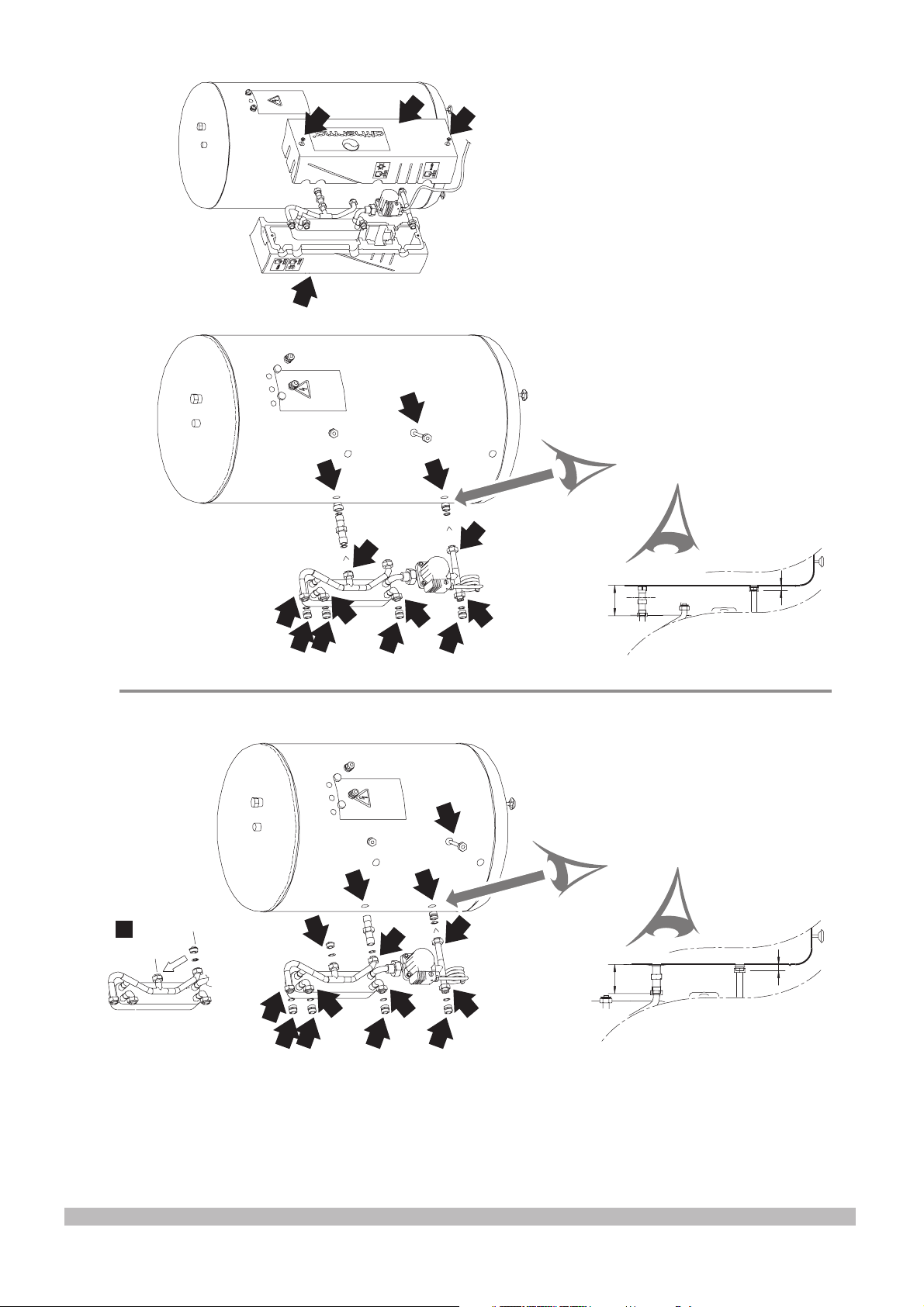
Installation of the solar kit ..................................................................4
Selecting an installation location .................................................4
Dimensions and service space....................................................4
Installation guidelines..................................................................5
Installing the solar kit...................................................................5
Field wiring ..................................................................................6
Start up ..............................................................................................8
Operating instructions........................................................................9
Configuring your system..............................................................9
Troubleshooting and servicing .........................................................11
General guidelines ....................................................................11
General symptoms ....................................................................11
Error codes................................................................................11
Disposal requirements.....................................................................11
Technical specifications ...................................................................12
Annexes...........................................................................................12
Decision flow of heating the domestic water
by heat pump or by solar kit ......................................................12
Decision flow of heating the domestic water
by booster heater ............................................................................. 13
Solar kit for air to water heat pump system
age
P
Installation and
operation manual
NTRODUCTION
I
General information
Thank you for purchasing this EKSOLHWAV1
solar kit.
The solar kit must be installed by a competent
person and be installed in compliance with the instructions in this
manual.
The solar kit is to be connected to the EKHW*
domestic hot water tank.
The solar kit will enable you to heat up your domestic water by means
of the sun whenever the sun is available.
To get the most comfort and energy savings out of your system,
make sure to observe the section "Configuring your system" on
page 9 of this manual.
Scope of this manual
This installation manual describes the procedures for installing and
operating the EKSOLHWAV1 solar kit.
Model identification
EK SOL HW A V1
V1 = 1P/230 V/50 Hz
Series
Domestic hot water
Solar kit
European Kit
READ THESE INSTRUCTIONS CAREFULLY BEFORE
INSTALLATION.
PLEASE LEAVE THIS MANUAL WITH THE EKSOLHW
SOLAR KIT AFTER INSTALLATION.
IMPROPER INSTALLATION OR ATTACHMENT OF
EQUIPMENT OR ACCESSORIES COULD RESULT IN
ELECTRIC SHOCK, SHORT-CIRCUIT, LEAKS, FIRE OR
OTHER DAMAGE TO THE EQUIPMENT. BE SURE ONLY
TO USE ACCESSORIES MADE BY DAIKIN WHICH ARE
SPECIFICALLY DESIGNED FOR USE WITH THE
EQUIPMENT AND HAVE THEM INSTALLED BY A
PROFESSIONAL.
IF UNSURE OF INSTALLATION PROCEDURES OR USE,
ALWAYS CONTACT YOUR DAIKIN DEALER FOR
ADVICE AND INFORMATION.
THE UNIT DESCRIBED IN THIS MANUAL IS DESIGNED
FOR INDOOR INSTALLATION ONLY AND FOR AMBIENT
TEMPERATURES RANGING 0°C~35°C.
EKSOLHWAV1
Solar kit for air to water heat pump system
4PW41598-1
Installation and operation manual
1
G
ENERAL
SYSTEM
1
2
3
4
5
6
7
8
SETUP
AND
OPERATION
Requirements and recommendations concerning field
supplied solar panels and solar pump station
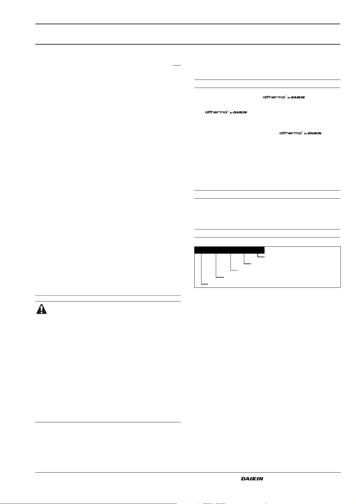
General system setup
The solar kit is designed to transfer the heat from the solar panels to
the heat exchanger of the domestic hot water tank EKHW* and is to
be installed in the system as shown in the
scheme below.
M
6
1
2
Solar panels (field supply)
Solar pump station (field supply)
Solar kit
Domestic hot water temperature sensor of the solar pump station
(field supply)
Domestic hot water temperature sensor of the indoor unit
Solar panel temperature sensor (field supply)
Solenoid 2-way valve (only for UK, refer to the EKUHW* kit)
Non-return valve (to be included in solar pump station or to be
installed in field piping)
Heating system.
Refer to the indoor unit installation manual.
8
3
7
5
4
Solar panel
Appropriate selection is to be made by your solar panel supplier, in
accordance with local regulations.
Solar pump station
The solar pump station must meet following requirements:
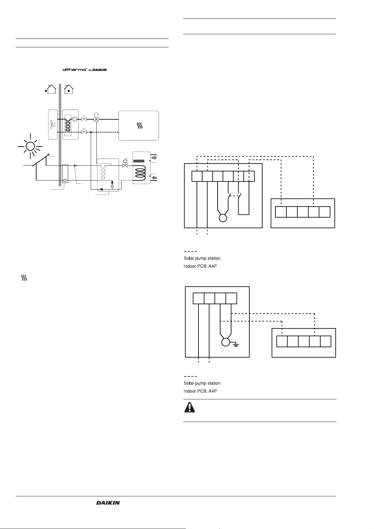
Electrical connection
The solar pump station will have an auxiliary contact that closes
when the contact for the pump of the solar pump station is operated.
This contact will provide 230 V to the input of the indoor unit, and
prevent domestic water heating by the heat pump and/or booster
heater during solar heating.
For wiring examples, refer to the following drawings.
Example 1
LNR1N
YC Y1 Y2 Y3 Y4
P
Solar pump station
230 V
Field wiring
Solar pump station
Indoor PCB: A4P
Example 2
Indoor PCB: A4P
The solar panels (1) catch the heat of the sun. When the temperature
of the glycol solution in the solar panel has become higher than the
water temperature in the domestic hot water tank, the pump of the
solar pump station (2) and the pump of the solar kit (3) start to
operate as to transfer the heat to the heat exchanger of the domestic
hot water tank, unless priority is given to the heat pump. Refer to
"Operating instructions" on page 9 (subsection: Configuring your
system).
LN R1N
P
Solar pump station Indoor PCB: A4P
YC Y1 Y2 Y3
230 V
Field wiring
Solar pump station
Indoor PCB: A4P
If the pump station has a speed controlled pump, make
sure to disable this function so that the indoor PCB
receives 230 V at all times.
Y4
Installation and operation manual
2
Solar kit for air to water heat pump system
EKSOLHWAV1
4PW41598-1
1x 5x1x1x 7x 2x 1x 1x 1x 2x
13 654
7
2
8
910
■
■
■
■
■
Settings
Maximum solar panel temperature
If the temperature of the solar panel is above this value, the
solar pump station will stop or not resume pump operation.
This setting will have a fixed value equal to or below 110°C , or
it will be possible to put this value equal to or below 110°C.
Putting this value to a higher value can break down
the pump of the solar pump station.
Also refer to the eye-catcher caution label that was torn up when
unpacking the installation manual.
Limiting the maximum solar panel temperature to 110°C
however, can affect efficiency of the solar panel.
But on the other hand:
as it is important for reliability of the pump in the solar pump
station only that temperature of the return water to that solar
pump is lower than 110°C;
and in case the 110°C limit for the return water temperature
to the solar pump can be guaranteed by other means than by
limiting the 'Maximum solar panel temperature';
then the value of the 'Maximum solar panel temperature' can be
set to a higher temperature.
Please contact your local solar panel dealer.
ON/OFF/AUTO
If the solar pump station has an ON/OFF/AUTO function, make
sure to put it on the AUTO function. This means that the pump
will switch on automatically when the solar panel temperature
rises sufficiently above the domestic hot water tank temperature
and switch off automatically when the difference between the
solar panel and the domestic hot water tank temperature
becomes too low.
Maximum tank temperature
When the maximum temperature of the domestic hot water tank
is reached, the solar pump station will stop pump operation.
Do not put this value above 80°C (70°C for units installed with
the EKUHW* kit) to avoid overheating of the domestic hot water
tank and the activation of the booster heater thermal protector in
the domestic hot water tank.
Some solar pump stations provide the possibility to still dump
heat to the domestic hot water tank, even when the maximum
domestic hot water tank temperature is already reached. This to
reduce the solar panel temperature by circulating the solar panel
fluid and transfer the heat to the domestic hot water tank.
If this function is present, it should be put to OFF as to avoid
thermal cut out operation of the tank.
NOTE
You can also change the domestic hot water
temperature setpoint on the controller of the indoor
unit. Refer to the operation manual of the indoor unit.
This temperature is sensed by the domestic hot water
temperature sensor of the indoor unit, located in the
upper thermistor holder of the domestic hot water tank.
For reasons of energy savings, it is advised to put this
temperature as low as possible without compromising
the required supply of hot water.
The maximum temperature that can be set in the
controller of the solar pump station is sensed by the
domestic hot water temperature sensor of the solar
pump station, located in the lower thermistor holder of
the domestic hot water tank.
Refer also to "Operating instructions" on page 9
(subsection: Configuring your system).
1
2
3
4
5
6
7
8
9
10
■
Anti-freeze setting
Some solar pump stations have an anti-freeze function. If the
solar panel temperature becomes too low, such solar pump
stations will circulate the solar fluid as to extract heat from the
tank and to avoid freezing of the solar fluid.
Make sure to disable this function.
Make sure the concentration of glycol in the solar panel
is big enough as to avoid freezing of the glycol at all
times.
Hydraulic connection
Make sure the solar pump station has non-return valves as to avoid
thermosiphon effect (migration of hot water to cold places). If the
solar pump station has no hydraulic connections included, install
them in the field piping as shown in "General system setup" on
page 2.
CCESSORIES
A
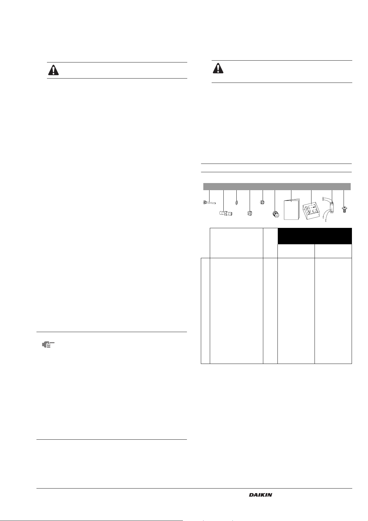
Accessories supplied with the solar kit
Necessary accessory for installation
of the solar kit for each type of
domestic hot water tank
EKHW* EKHWSU
150* 200* 300* 150* 200* 300*
Thermistor socket 1/2"
Male BSP (internal
diameter 6.1)
Connection pipe 3/4" Male
BSP x 3/4” Male BSP
Sealing 7 677766
Adaptor 3/4" Female
BSP x 3/4" Male BSP
Adaptor 3/4" Male
BSP x 3/4" Male BSP
PG nipple and nut 2 222222
Installation manual 1 111111
EKRP1HB solar/remote
alarm address card
Solar contactor assembly
K7M
Contactor fixing screw 2 222222
Quantity
1 111111
1 111———
1—11———
5 555455
1 111111
1 111111
■
Minimum temperature difference between domestic hot water
tank and solar panel before starting pump operation
This minimum temperature difference will be put equal to or
above 10°C.
EKSOLHWAV1
Solar kit for air to water heat pump system
4PW41598-1
Installation and operation manual
3
■
■
■
■
■
1
2
3
4
5
6
7a
7b
8
9
10
O
VERVIEW
OF
Main components
5
3
2
4
10
1
6
10
8
Solar kit circulation pump
Heat exchanger
Inlet connection from solar pump station
Return connection to solar pump station
Inlet connection from the indoor unit
Return connection to the indoor unit
Return connection to the 200/300 l domestic hot water tank heat
exchanger
Return connection to the 150 l domestic hot water tank heat
exchanger
Inlet connection from the domestic hot water tank heat exchanger
EPP casing
Non-return valves
THE
SOLAR
7a
KIT
I
NSTALLATION
OF
THE
SOLAR
KIT
Selecting an installation location
7b9
9
The solar kit is to be installed in a frost free indoor space,
directly connected to the domestic hot water tank.
Make sure the service space is available as indicated in below
drawing.
The space around the unit has to allow sufficient air circulation.
It shall be made sure that in the case of a leak, leaking water will
not cause any damage or unsafe situations.
Do not install or operate the unit in rooms mentioned below:
- Where corrosive gas like sulphurous gas exists: copper
tubing and brazed spots may corrode.
- Where volatile flammable gas like thinner or gasoline is used.
- Where machines generating electromagnetic waves exist:
the control system may malfunction.
- Where the air contains high levels of salt such as air near the
ocean and where voltage fluctuates a lot (e.g. in factories).
This applies also to vehicles or vessels.
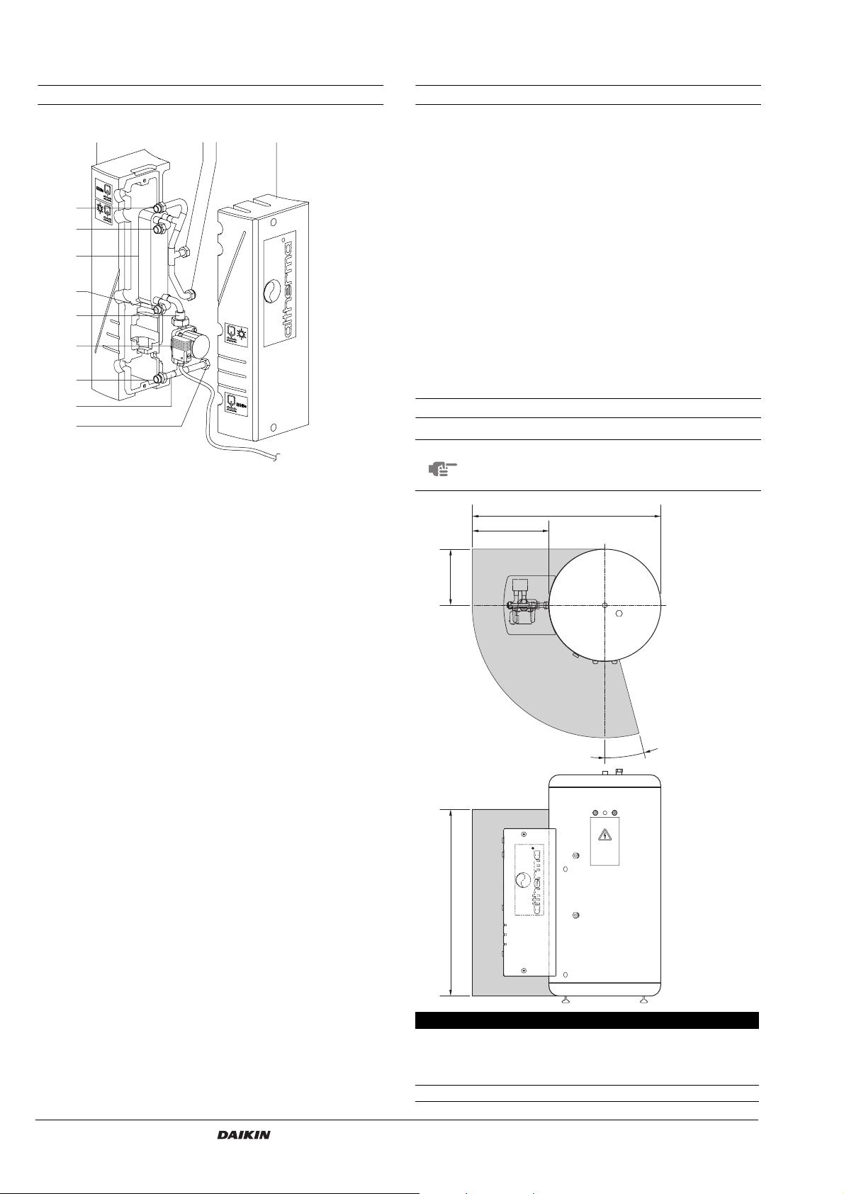
Dimensions and service space
NOTE
For installation of the solar kit to the EKHWSU150*
domestic hot water tank (UK only), the solar kit will not
fit entirely tight to the tank.
A
B
290
Safety functions
Thermal cut out
The solar kit is electrically connected with the thermal cut out safety
of the domestic hot water tank. (refer to "Field wiring" on page 6).
When the thermal cut out safety of the domestic hot water trips, the
power supply to the pump of the solar kit is interrupted so that no
more solar heat can be transferred to the domestic hot water tank.
Solenoid 2-way valve (only for UK)
The thermostat will close the solenoid 2-way valve when the
temperature becomes too high (setting 79°C).
°
5
1
971
A B
EKHW*150*
EKHW*200*
EKHW*300*
EKHWSU200*
EKHWSU300*
EKHWSU150* 1010 430
980 400
Installation and operation manual
4
Solar kit for air to water heat pump system
EKSOLHWAV1
4PW41598-1
 Loading...