

Page 1

EKOMBG22AAV1
EKOMBG28AAV1
EKOMBG33AAV1
Installation instructions English
Daikin Europe NV
Page 2

CE - ATITIKTIES-DEKLARACIJA
<A> 177155_EMC2/03-2011
<B> KIWA (NB0063)
<C> -
CE - ATBILSTĪBAS-DEKLARĀCIJA
CE - VYHLÁSENIE-ZHODY
CE - UYGUNLUK-BEYANI
CE - IZJAVA O SKLADNOSTI
CE - VASTAVUSDEKLARATSIOON
CE - ДЕКЛАРАЦИЯ-ЗА-ϹЪОТВЕТСТВИЕ
CE - IZJAVA-O-USKLAĐENOSTI
CE - MEGFELELŐSÉGI-NYILATKOZAT
CE - DEKLARACJA-ZGODNOŚCI
CE - DECLARAŢIE-DE-CONFORMITATE
deklaruje na własną i wyłączną odpowiedzialność, że urządzenia, których ta deklaracja dotyczy:
m
17
относи тся настоящее заявление:
у
declară pe proprie răspundere că echipamentele la care se referă această declaraţie:
r
18
z vso odgovornostjo izjavlja, da je oprema naprav, na katero se izjava nanaša:
kinnitab oma täielikul vastutusel, et käesoleva deklaratsiooni alla kuuluv varustus:
o
x
19
20
декларира на своя отговорност, че оборудването, за коeто се отнася тази декларация:
b
21
visiška savo atsakomybe skelbia, kad įranga, kuriai taikoma ši deklaracija:
t
22
ar pilnu atbildību apliecina, ka tālāk aprakstītās iekārtas, uz kurām attiecas šī deklarācija:
v
23
vyhlasuje na vlastnú zodpovednosť, že zariadenie, na ktoré sa vzťahuje toto vyhlásenie:
k
24
tamamen kendi sorumluluǧunda olmak üzere bu bildirinin ilgili olduǧu donanımının aşaǧıdaki gibi olduǧunu beyan eder:
w
25
megfelelnek az alábbi szabvány(ok)nak vagy egyéb irányadó dokumentum(ok)nak, ha azokat előírás szerint használják:17spełniają wymogi następujących norm i innych dokumentów normalizacyjnych, pod warunkiem że używane są zgodnie z naszymi
16
instrukcjami:
sunt în conformitate cu următorul (următoarele) standard(e) sau alt(e) document(e) normativ(e), cu condiţia ca acestea să fie utilizate în
conformitate cu instrucţiunile noastre:19skladni z naslednjimi standardi in drugimi normativi, pod pogojem, da se uporabljajo v skladu z našimi navodili:20on vastavuses järgmis(t)e standardi(te)ga või teiste normatiivsete dokumentidega, kui neid kasutatakse vastavalt meie juhenditele:21съответстват на следните стандарти или други нормативни документи, при усл овие, че се използват съгласно нашите
18
инструкции:
atitinka žemiau nurodytus standartus ir (arba) kitus norminius dokumentus su sąlyga, kad yra naudojami pagal mūsų nurodymus:23tad, ja lietoti atbilstoši ražotāja norādījumiem, atbilst sekojošiem standartiem un citiem normatīviem dokumentiem:24sú v zhode s nasledovnou(ými) normou(ami) alebo iným(i) normatívnym(i) dokumentom(ami), za predpokladu, že sa používajú v súlade
22
Direktive z vsemi spremembami.20Direktiivid koos muudatustega.21Директиви, с техните изменения.22Direktyvose su papildymais.23Direktīvās un to papildinājumos.24Smernice, v platnom znení.25Deǧiştirilmiş halleriyle Yönetmelikler.
19
Direktiver, med senere ændringer.11Direktiv, med företagna ändringar.12Direktiver, med foretatte endringer.13Direktiivejä, sellaisina kuin ne ovat muutettuina.14v platném znění.15Smjernice, kako je izmijenjeno.16irányelv(ek) és módosításaik rendelkezéseit
10
s našim návodom:25ürünün, talimatlarımıza göre kullanılması koşuluyla aşağıdaki standartlar ve norm belirten belgelerle uyumludur:
Directives, as amended.02Direktiven, gemäß Änderung.03Directives, telles que modifiées.04Richtlijnen, zoals geamendeerd.05Directivas, según lo enmendado.06Direttive, come da modifica.07Οδηγιών, όπως έχουν τροποποιηθεί.08Directivas, conforme alteração em.09Директив со всеми поправками.
01
.
<B>
<B>
göre
.
.
pozitīvajam
<B>
.
un atbilstoši
<A>
kā norādīts
23 Piezīmes *
şi apreciat pozitiv
<A>
aşa cum este stabilit în
sertifikātu <C>
vērtējumam saskaņā ar
.
Certificatul <C>
în conformitate cu
<B>
de
a pozitívne zistené
<A>
osvedčením <C>
v súlade s
ako bolo uvedené v
24 Poznámka *
<B>
.
in odobreno s strani
<A>
certifikatom <C>
kot je določeno v
v skladu s
<C> Sertifikasına
’da belirtildiği gibi ve
25 Not * <A>
ja heaks
<A>
nagu on näidatud dokumendis
tarafından olumlu olarak değerlendirildiği gibi.
<B>
.
sertifikaadile <C>
järgi vastavalt
<B>
kiidetud
z późniejszymi poprawkami.18Directivelor, cu amendamentele respective.
17
и оценено положително
<A>
* както е изложено в
21 Забележка
igazolta a megfelelést,
<B>
alapján, a(z)
<A>
a(z)
Сертификата <C>
съгласно
<B>
от
szerint.
<C> tanúsítvány
a(z)
ir kaip teigiamai nuspręsta
<A>
kaip nustatyta
22 Pastaba *
, pozytywną opinią
<A>
zgodnie z dokumentacją
.
Sertifikatą <C>
pagal
.
Świadectwem <C>
i
<B>
к котором
оборудование,
CE - ERKLÆRING OM-SAMSVAR
CE - ILMOITUS-YHDENMUKAISUUDESTA
CE - PROHLÁŠENÍ-O-SHODĚ
заявляет, исключительно под свою ответственность, что
erklærer under eneansvarlig, at udstyret, som er omfattet af denne erklæring:
erklærer et fullstendig ansvar for at det utstyr som berøres av denne deklarasjon innebærer at:
ilmoittaa yksinomaan omalla vastuullaan, että tämän ilmoituksen tarkoittamat laitteet:
prohlašuje ve své plné odpovědnosti, že zařízení, k němuž se toto prohlášení vztahuje:
izjavljuje pod isključivo vlastitom odgovornošću da oprema na koju se ova izjava odnosi:
j
13
c
14
y
15
teljes felelőssége tudatában kijelenti, hogy a berendezések, melyekre e nyilatkozat vonatkozik:
h
16
deklarerar i egenskap av huvudansvarig, att utrustningen som berörs av denna deklaration innebär att:
u
q
n
s
09
10
11
12
CE - FÖRSÄKRAN-OM-ÖVERENSTÄMMELSE
CE - DECLARAÇÃO-DE-CONFORMIDADE
CE - ЗАЯВЛЕНИЕ-О-СООТВЕТСТВИИ
CE - OVERENSSTEMMELSESERKLÆRING
CE - DECLARACION-DE-CONFORMIDAD
CE - DICHIARAZIONE-DI-CONFORMITA
CE - ∆HΛΩΣΗ ΣΥΜΜΟΡΦΩΣΗΣ
estão em conformidade com a(s) seguinte(s) norma(s) ou outro(s) documento(s) normativo(s), desde que estes sejam utilizados de
acordo com as nossas instruções:09соответствуют следующим стандартам или другим нормативным документам, при условии их использования согласно нашим
08
16 Megjegyzés *
17 Uwaga *
18 Notă *
19 Opomba *
20 Märkus *
on
Low Voltage 2006/95/EC
Gas Appliances 2009/142/EC
Boiler Efficiency requirements 92/42/EEC
инструкциям:
overholder følgende standard(er) eller andet/andre retningsgivende dokument(er), forudsat at disse anvendes i henhold til vore
instrukser:11respektive utrustning är utförd i överensstämmelse med och följer följande standard(er) eller andra normgivande dokument, under
förutsättning att användning sker i överensstämmelse med våra instruktioner:12respektive utstyr er i overensstemmelse med følgende standard(er) eller andre normgivende dokument(er), under forutssetning av at
disse brukes i henhold til våre instrukser:13vastaavat seuraavien standardien ja muiden ohjeellisten dokumenttien vaatimuksia edellyttäen, että niitä käytetään ohjeidemme
10
mukaisesti:14za předpokladu, že jsou využívány v souladu s našimi pokyny, odpovídají následujícím normám nebo normativním dokumentům:15u skladu sa slijedećim standardom(ima) ili drugim normativnim dokumentom(ima), uz uvjet da se oni koriste u skladu s našim uputama:
ob upoštevanju določb:20vastavalt nõuetele:21следвайки клаузите на:22laikantis nuostatų, pateikiamų:23ievērojot prasības, kas noteiktas:24održiavajúc ustanovenia:25bunun koşullarına uygun olarak:
19
under iagttagelse af bestemmelserne i:11enligt villkoren i:12gitt i henhold til bestemmelsene i:13noudattaen määräyksiä:14za dodržení ustanovení předpisu:15prema odredbama:16követi a(z):17zgodnie z postanowieniami Dyrektyw:18în urma prevederilor:
10
enligt
<B>
.
och godkänts av
Electromagnetic Compatibility 2004/108/EC *
<A>
enligt
Certifikatet <C>
11 Information *
.
Certificato <C>
e giudicato positivamente
<A>
secondo il
<B>
delineato nel
da
06 Nota *
<B>
.
and judged positively by
Certificate <C>
<A>
as set out in
according to the
.
<B>
ja jotka
<A>
Sertifikat <C>
og gjennom positiv
<A>
ifølge
<B>
bedømmelse av
som det fremkommer i
jotka on esitetty asiakirjassa
12 Merk *
13 Huom *
.
e com o parecer
και κρίνεται θετικά από
<A>
Πιστοποιητικό <C>
<A>
σύμφωνα με το
<B>
όπως καθορίζεται στο
tal como estabelecido em
το
07 Σημείωση *
08 Nota *
positiv beurteilt
<B>
et évalué positivement par
.
<A>
aufgeführt und von
Zertifikat <C>
<A>
gemäß
wie in
tel que défini dans
<B>
.
mukaisesti.
a pozitivně zjištěno
i pozitivno ocijenjeno
<A>
<A>
osvědčením <C>
Sertifikaatin <C>
hyväksynyt
v souladu s
jak bylo uvedeno v
kako je izloženo u
14 Poznámka *
15 Napomena *
.
согласно
Certificado <C>
<B>
.
и в соответствии
de acordo com o
<A>
<B>
как указано в
Свидетельству <C>
positivo de
сположительным решением
09 Примечание *
.
.
y es valorado
Certificat <C>
<A>
Certificaat <C>
en positief beoordeeld door
<A>
conformément au
overeenkomstig
<B>
zoals vermeld in
<B>
como se establece en
.
Certifikatu <C>
prema
<B>
od strane
<B>
og positivt vurderet af
<A>
som anført i
10 Bemærk *
de acuerdo con el
<B>
positivamente por
Shigeki Morita
Director
Ostend, 3rd of March 2014
.
Certifikat <C>
i henhold til
.
Certificado <C>
CE - DECLARATION-OF-CONFORMITY
CE - KONFORMITÄTSERKLÄRUNG
CE - DECLARATION-DE-CONFORMITE
CE - CONFORMITEITSVERKLARING
declares under its sole responsibility that the equipment to which this declaration relates:
erklärt auf seine alleinige Verantwortung daß die Ausrüstung für die diese Erklärung bestimmt ist:
déclare sous sa seule responsabilité que l'équipement visé par la présente déclaration:
verklaart hierbij op eigen exclusieve verantwoordelijkheid dat de apparatuur waarop deze verklaring betrekking heeft:
declara bajo su única responsabilidad que el equipo al que hace referencia la declaración:
dichiara sotto la propria responsabilità che gli apparecchi a cui è riferita questa dichiarazione:
δηλώνει με αποκλειστική της ευθύνη ότι ο εξοπλισμός στον οποίο αναφέρεται η παρούσα δήλωση:
declara sob sua exclusiva responsabilidade que os equipamentos a que esta declaração se refere:
a
d
f
l
e
i
g
Daikin Europe N.V.
01
02
03
04
p
05
06
EKOMBG22AAV1*, EKOMBG28AAV1*, EKOMBG33AAV1*,
07
08
EKOMB22AAV1*, EKOMB28AAV1*, EKOMB33AAV1*,
are in conformity with the following standard(s) or other normative document(s), provided that these are used in accordance with our
der/den folgenden Norm(en) oder einem anderen Normdokument oder -dokumenten entspricht/entsprechen, unter der Voraussetzung,
daß sie gemäß unseren Anweisungen eingesetzt werden:03sont conformes à la/aux norme(s) ou autre(s) document(s) normatif(s), pour autant qu'ils soient utilisés conformément à nos instructions:04conform de volgende norm(en) of één of meer andere bindende documenten zijn, op voorwaarde dat ze worden gebruikt overeenkomstig
instructions:
* = , , 1, 2, 3, ..., 9
01
onze instructies:05están en conformidad con la(s) siguiente(s) norma(s) u otro(s) documento(s) normativo(s), siempre que sean utilizados de acuerdo con
02
nuestras instrucciones:
με τις οδηγίες μας:
sono conformi al(i) seguente(i) standard(s) o altro(i) documento(i) a carattere normativo, a patto che vengano usati in conformità alle
nostre istruzioni:07είναι σύμφωνα με το(α) ακόλουθο(α) πρότυπο(α) ή άλλο έγγραφο(α) κανονισμών, υπό την προϋπόθεση ότι χρησιμοποιούνται σύμφωνα
06
following the provisions of:02gemäß den Vorschriften der:03conformément aux stipulations des:04overeenkomstig de bepalingen van:05siguiendo las disposiciones de:06secondo le prescrizioni per:07με τήρηση των διατάξεων των:08de acordo com o previsto em:09в соответствии с положениями:
01
EN60335-2-40,
01 Note *
02 Hinweis *
03 Remarque *
04 Bemerk *
05 Nota *
2P369568-1
Page 3

TABLE OF CONTENTS
1
2
3
4
5
6
7
8
9
10
11
© 2014 Daikin Europe NV
All rights reserved.
The information provided applies to the product in its standard version. Daikin Europe NV can therefore not be held liable for any damages arising from any
specifications of the product which deviate from the standard version. The available information has been compiled with the greatest possible care, but Daikin Europe
NV can not be held liable for any mistakes in the information, or for any consequences thereof. Daikin Europe NV cannot be held liable for any damage arising from
work carried out by third parties.
Subject to change.
Safety instructions 4
Unit description 5
2.1 General ............................................................................................................................................................................................ 5
2.2 Functioning ...................................................................................................................................................................................... 5
2.3 Operating modes ............................................................................................................................................................................. 5
2.4 PC Interface .................................................................................................................................................................................... 7
2.5 Test programs ................................................................................................................................................................................. 7
Main components 8
3.1 Accessories ..................................................................................................................................................................................... 9
Installation 10
4.1 Installation measurements ............................................................................................................................................................ 10
4.2 Installation space ........................................................................................................................................................................... 12
4.3 Assembly ....................................................................................................................................................................................... 13
Connecting 14
5.1 Connecting CH installation ............................................................................................................................................................ 15
5.2 Connecting DHW installation ......................................................................................................................................................... 17
5.3 Connecting electronically .............................................................................................................................................................. 18
5.4 Connect room thermostat .............................................................................................................................................................. 19
5.5 Connecting gas ............................................................................................................................................................................. 20
5.6 Flue gas output and air input ......................................................................................................................................................... 21
5.7 Outlet systems ............................................................................................................................................................................... 22
Commissioning the unit and the Installation 35
6.1 Filling and air purge of unit and installation ................................................................................................................................... 35
6.2 Commissioning the unit ................................................................................................................................................................. 36
6.3 Switching off the unit ..................................................................................................................................................................... 37
Setting and adjustment 38
7.1 Direct via operating panel .............................................................................................................................................................. 38
7.2 Parameter settings via the service code ....................................................................................................................................... 39
7.3 Setting maximum CH power .......................................................................................................................................................... 41
7.4 Set pump capacity ......................................................................................................................................................................... 41
7.5 Weather dependent regulation ...................................................................................................................................................... 41
7.6 Conversion to different type of gas................................................................................................................................................ 42
7.7 Gas/air regulation .......................................................................................................................................................................... 42
7.8 Setting gas/air regulation ............................................................................................................................................................... 43
Malfunctions 45
8.1 Show last malfunction ................................................................................................................................................................... 45
8.2 Malfunction codes ......................................................................................................................................................................... 45
Maintenance 49
Technical specifications 51
10.1 Electrical diagram .......................................................................................................................................................................... 52
10.2 NTC resistances ............................................................................................................................................................................ 53
Warranty conditions 54
Daikin Europe NV
3
Page 4

These installation instructions
Description
To be referred to as
High Efficiency
HR
Daikin EKOMBG22AAV1, EKOMBG28AAV1 and
Unit
Unit with piping for central heating
CH installation
System with pipes for domestic hot water
DHW installation
CAUTION
IMPORTANT
will have a negative effect on the functioning of the
With these installation instructions, you can safely assemble, install and maintain the
unit. Carefully follow the instructions.
In case of any doubt, please contact the manufacturer.
Keep the installation instructions near the unit.
Abbreviations and terms used
EKOMBG33AAV1 wall-mounted gas boiler.
Symbols
The following symbols are used in this manual:
Procedures which - if they are not carried out with the
necessary care - may cause damage to the product, the
surroundings, the environment or injury.
Procedures and/or instructions which, if they are not
followed,
unit.
Service and technical support for the installer
For information about specific settings, installation, maintenance and repair work, as
an installer, please contact your local Daikin dealer.
Identification of the product
You will find the unit details on the type plate on the bottom of the unit.
A. Unit type
B. Bar code with article number and serial number
C. Options
1 SAFETY INSTRUCTIONS
The manufacturer Daikin accepts no liability for damage or injury caused by the
failure to (strictly) observe the safety instructions, or negligence during the
installation of the Daikin EKOMBG*AAV1 wall-mounted gas boiler and any
associated accessories.
This device is not intended for use by people (including children) with reduced
physical, sensory or mental abilities, or lack of experience and knowledge, unless
they are given supervision or instructions on the use of the device by a person who
is responsible for their safety.
The instructions are stated separately for the various disciplines.
The entire installation must meet the applicable local technical and (safety)
instructions, for the gas installation, the electrical installation, smoke extraction
installation, drinking water installation, and central heating installation.
Daikin Europe NV 4
Page 5

2 UNIT DESCRIPTION
2.1 General
The Daikin EKOMBG*AAV1 wall-mounted gas boiler is a closed unit. The unit is
intended to provide heat to the water of a CH-installation and the domestic hot water
installation.
The air supply and the combustion gas outlet of the EKOMBG*AAV1 can be connected
to the unit by two separate pipes, or by a concentric connection. The unit was tested in
combination with the combi feedthrough, but the unit may also be connected to combi
feedthroughs which meet the universal test standards for combi feedthroughs.
The unit can be connected to an assembly bracket if required, a frame with top
connection, and various installation sets. These are provided separately.
The Daikin EKOMBG*AAV1 wall-mounted gas boilers have the CE quality mark,
electrical protection class IP44.
It is possible to use the unit solely for warm water, or solely for heating. The system
which is not in use, does not need to be connected (see par. 7.2).
The unit is delivered for natural gas (G25) as a standard. On request, the unit can also
be provided for propane (G31).
2.2 Functioning
The Daikin EKOMBG*AAV1 wall-mounted gas boiler is a modulating high-efficiency
boiler. This means that the power is modulated to suit the required heat demand. In the
aluminum heat exchanger two separate copper circuits are integrated.
The separate circuits for CH and warm water allow the heating and warm water supply
to function independently. The hot water supply takes precedence over the heating.
Both cannot work at the same time.
The unit is fitted with an electronic boiler controller machine, which operates the fan
and the modulating pump at every heat requirement of the heating or the warm water
supply, opens the gas valve, ignites the boiler controller, and continuously monitors
and regulates the flame, depending on the requested power. The pump is only
operated during a heat request from the heating, depending on the requested power.
2.3 Operating modes
The operating mode of the unit is indicated by means of a code on the service display
of the operating panel.
-
Off
The unit is not in operation, but is connected to the electricity supply. No response is
given to requests for domestic hot water or CH water. The unit frost protection is
active. This means that the pump will start running and the exchanger will be heated
up if the temperature of the water in the system drops too far.
If the frost protection intervenes, the code
The pressure in the CH installation can also be read from the temperature display in
this operating mode (in bar).
Standby
The LED at the key is lit and possibly one of the LEDs of the tap comfort function.
The unit is ready to respond to a request for CH or tap water.
0
Post-running CH
After the end of the CH-operation, the pump will post-run. The post-pumping time is set
to the value in par. 7.2 in its factory settings. This setting can be changed. In addition
to this, the pump will run automatically 1 time per 24 hours, for 10 seconds, in order to
prevent it from getting stuck. This automatic switching on of the pump takes place at
the time of the last heating request. In order to change this, the room thermostat needs
to be set higher for a moment, at the required time of day.
1
Requested temperature reached
The boiler controller may temporarily block the heat request. The boiler controller will
then be stopped. The block occurs because the required temperature has been
reached. When the temperature has sufficiently decreased, the block will be lifted.
Daikin Europe NV
7
will be displayed (heating up exchanger).
5
Page 6

2
Selftest
Once every 24 hours, the boiler controller tests the connected sensors. During the
test, the controller will not carry out any other tasks.
3
Ventilating
When the unit is started, the fan is first brought up to its correct start rpm. When the
start rpm is reached, the boiler controller will be ignited. Code 3 is also visible when
there is post-fanning after the boiler controller is stopped.
4
Igniting
When the fan has reached the start rpm, the boiler controller will be ignited by means
of electrical sparks. During the ignition, code
does not ignite, a new attempt will be made after approximately 15 seconds. If after 4
ignition attempts, the boiler controller has still not been ignited, the controller will go
into down-time.
5
CH-operation
An on/off thermostat, an OpenTherm thermostat, an outdoor sensor or a combination
thereof can be connected to the controller (see par. 10.1)
When there is a heat request from a thermostat, after the fan has started running
(code 3 ), the ignition will take place (code
(code 5 ).
During CH operation, the rpm of the fan and therefore the power of the unit can be
adjusted so the temperature of the CH water to the required CH supply temperature
can be controlled. If an on/off thermostat has been connected, this will be the CH
supply temperature set on the display. In case of an OpenTherm or wireless
thermostat, the required CH supply temperature is determined by the thermostat. In
case of an outdoor sensor, the required CH supply temperature is determined by the
fuel line programmed in the boiler controller. For the last two situations, the
temperature set on the display is the maximum.
During CH operation, the requested CH supply temperature will be displayed on the
operating panel.
The CH supply temperature can be set between 30 and 90°C (see par. 7.1). Caution:
for a low temperature system, a lower maximum setting may be required than the
standard setting of 80°C.
You can press the service button during CH operation to read the actual CH supply
temperature.
4
is displayed. If the boiler controller
4
) followed by the CH operating mode
If the tap comfort function is switched on (see code
of less than 40 degrees will be generated.
6
Domestic hot water operation
The hot water supply takes precedence over the heating. If the flow switch senses a
request for more than 2 l/min of domestic hot water, any CH requests will be
interrupted. After the fan has switched on (code
(code 4 ), the controller will switch to domestic water operation (code
domestic hot water operation, the rpm of the fan, and therefore the power of the unit,
is controlled by the controller on the basis of the set tap water temperature.
The control system ensures the tap water temperature is correct. The water
temperature can be set between 40°C and 65°C (see par. 7.1).
The set tap water temperature is displayed on the operation panel. The standard
setting is 60°C.
You can press the service button during tap water operation to read the actual tap
water temperature.
7
Heating up unit
In order to provide a fast supply of domestic hot water, a so-called tap comfort
function has been installed in the unit. This function keeps the heat exchanger at the
right temperature (it can be set, see par. 7.2). The tap comfort function has the
following settings:
•
On: ( LED on) The tap comfort function of the unit is continuously switched on.
7
), an OpenTherm heat request
3
) and there has been an ignition
6
). During
Daikin Europe NV 6
Page 7

The unit always immediately provides warm water.
Description of program
Button combination
Display reading
Burner on with minimum
DHW
Burner on with set maximum CH
Burner on with maximum
DHW power
Current operation
The unit is fitted with frost protection in order to prevent it from
ntervenes, code
frost thermostat on the return pipe.
•
Eco: ( LED on) The tap comfort function of the unit is self-learning. The unit will
adjust to the usage pattern of the domestic hot water. This means the heat
exchanger will not be kept warm during the night or during longer absences.
•
Off: (Both LEDs off) The heat exchanger is not kept warm which means the supply of
domestic hot water takes a bit of time. If there is no need for fast delivery of domestic
hot water, the tap comfort function can be switched off.
In the settings "on" and "eco" , the unit meets the requirements of the Gaskeur
[Gas Inspection] CW standards.
2.4 PC Interface
The boiler controller is provided with an interface for a PC. A PC can communicate with
the CH boiler by means of a special dongle, and the associated software. This facility
enables you to follow the behavior of the boiler controller, the unit and the heat
installation over a long period.
2.5 Test programs
There is an option in the boiler controller, to bring the unit into a test status.
Activating a test program, will switch on the unit with a set fan rotations per minute,
without the control functions intervening.
The safety functions do remain active.
The test program is ended by pressing and simultaneously.
Test programs
capacity (see parameter d par. 7.2)
power (see parameter 3 par. 7.2)
(see parameter 3 par. 7.2)
Switching off test program and
and
and (1x)
and (2x)
"L"
"h"
"H"
situation
2.5.1 Frost protection
•
freezing. If the temperature of the heat exchanger drops too low,
the pump will start running until the temperature of the heat
exchanger is sufficiently high. If the frost protection i
7‘
will be displayed (heating up exchanger).
•
If the installation (or a part thereof) can freeze, the coldest place
should be fitted with an (external)
This must be connected in accordance with the electrical diagram
(see par. 10.1).
Note
When the unit is switched off (
remain active, however a heat request from an (external) frost thermostat will be ignored.
-
on the service display), the unit frost protection will
Daikin Europe NV
7
Page 8

3 MAIN COMPONENTS
A. CH
pump L. Air supply (only when using twin pipe flue system)
B. Gas
valve M. Flue gas/air inlet concentric adapter
C. Burner
controller
(incl. operating panel)
N.
Connection block / terminal strip X4
D. Sensor S1 (flow)
O.
Condensate drain pan
E. Sensor S2 (return)
P.
Domestic hot water
sensor S3
F. Fan Q. Siphon
G. Flow sensor
R.
Heat exchanger
H. Pressure sensor central heating
S.
Operating panel and display
I. Connection wire 230 V ~ with earthed plug
T.
Ionization / ignition pen
J. Manual air bleed
U.
Position
of data plate
K. Sight glass
Daikin Europe NV 8
Page 9

3.1 Accessories
Description
Article numbers
B-pack EKFJS*AA
EKFJS*AA
B-pack middle
EKFJM*AA
B-pack large
EKFJL*AA
Valve kit
EKVK4AA
Cover
plate EKOMBG*AAV1
EKCP1AA
O
utdoor
sensor
EKOSK1AA
3-way valve set
EK3WV1AA
Flue gas adapter Concentric
Ø
80x125
EKHY090717
Flue gas adapter Parallel 80 mm
EKHY090707
Propane set
*KOMBG22AAV1
EKPS075877
Propane set *KOMBG28AAV1
EKPS075867
Propane set *KOMBG33AAV1
EKHY075787
Daikin Europe NV
9
Page 10

4 INSTALLATION
A = Supply CH
G ¾” (ext)
B = Return CH
G ¾” (ext)
C = Gas G ½” (int)
D = Tap water cold
G ½” (ext)
E = Tap water warm
G ½” (ext)
F = Condense outlet
Ø dn25 (flexible)
h= 517mm
EKOMBG22AAV1
577mm
EKOMBG28AAV1
637mm
EKOMBG33AAV1
H= 590mm
EKOMBG22AAV1
650mm
EKOMBG28AAV1
710mm
EKOMBG33AAV1
Z = Flue gas outlet/air
Ø60/100 (concentric)
020601002
161
161
450
240
135
h
77
75
4.1 Installation measurements
Boiler mounted directly to the wall
Connections:
inlet
Daikin Europe NV 10
Page 11

A = Supply CH
G ¾” (ext)
B = Return CH
G ¾” (ext)
C = Gas G ½” (int)
D = Tap water cold
G ½” (ext)
E = Tap water warm
G ½” (ext)
F = Condense outlet
Ø dn25 (flexible)
H= 770mm
EKOMBG22AAV1
830mm
EKOMBG28AAV1
890mm
EKOMBG33AAV1
Z = Flue gas outlet/air
Ø60/100 (concentric)
020601001
265
265
77
75
Unit connected to B-pack:
Connections:
inlet
Daikin Europe NV
11
Page 12

4.2 Installation space
IMPORTANT
The unit must be installed against a wall with sufficient load bearing capacity.
In case of light wall constructions, there is a risk of resonance noises.
Within 1 meter of the unit, there must be a earthed wall plug.
In order to prevent the condense outlet from freezing, the unit must be installed in a
frost-free room. Preferably ensure there is a space of at least 2 cm next to the boiler.
No free space is required due to danger of singeing.
The unit must not be installed in a space where work is carried out
with aggressive or corrosive gases such as hairspray.
4.2.1 Installing in kitchen cabinet
The unit can be placed between two kitchen cabinets, or inside a kitchen cabinet.
Make sure there is sufficient ventilation at the bottom and the top.
If the unit is installed inside a cabinet, ventilation openings of at least 50 cm
required.
4.2.2 Removing cover plate and front panel
For various activities on the unit, the cover plate and front panel have to be removed
from the unit, if they were installed. Do this as follows:
• If you are using the cover plate (A), remove it to the front.
• Unscrew both screws (1) behind the display window.
• Pull the bottom of the front panel (2) forwards.
Danger: risk of burning
In case of high leaving water set ponts for space heating (eighter a high fixed set point
or a high weather-dependent set point at low ambient temperatures), the heat
exchanger of the boiler can be very hot, for example 70°C.
Beware that in case of a tapping demand, the water can initially have a higher water
temperature than requested.
In this case, it is recommended to install a thermostatic valve to prevent scalding.
This can be done according to the schematics below.
2
are
Daikin Europe NV 12
Page 13

4.3 Assembly
020601020
The boiler can be hung to the wall using :
•
the wall suspension strip and a the connection kit EKVK4AA
•
a B-pack including an expension vessel and a connection kit.
4.3.1 Assembling suspension strip and assembly bracket
• Make sure the construction of the wall is suitable for hanging the boiler.
• Drill the holes for the suspension strip and the connection kit in the wall
using the template delivered with the boiler.
• Mount the suspension strip and the assembly bracket horizontally on the
wall, using the associated attachment materials.
• Place the filling loop on the connections of the return and cold water nipple
following the connection kit installation instruction
• The boiler can now be placed on the suspension strip simultaniously sliding
the pipes of the boiler into the valves in the assembly bracket.
4.3.2 Assembling bottom connection set
• Make sure the construction of the wall is suitable for hanging the boiler and
B-pack.
• Drill the holes for the B-pack kit in the wall using the template delivered
with the boiler.
• Mount the B-pack on the wall using the associated attachment materials.
• Place the assembly bracket in the frame as described in the manual
inclued in the B-pack.
• Connect the flexible hose on the expension vessel and the conenction on
the return valve. Make sure the seal rings are placed !
• Place the filling loop on the connections of the return and cold water nipple
following the connection kit installation instruction
• The boiler can now be placed on B-pack simultaniously sliding the pipes of
the boiler into the valves in the assembly bracket
Daikin Europe NV
13
Page 14

4.3.3 Assembling the unit
1. Unpack the unit.
2. Check the content of the packaging, which consists of:
• Unit (A)
• Suspension strip (B)
• Siphon (C)
• Flexible tube (D)
• Installation instructions
• Operating instructions
• Warranty card
3. Check the unit for any damage: immediately report damages to the supplier.
4. Install the suspension strip.
5. Check whether the compression rings are positioned straight in the couplings of
the assembly bracket.
6. Position the unit: slide it from top to bottom over the suspension strip (B). Make
sure the pipes slide into the compression fittings simultaneously.
7. Tighten the compression fittings onto the assembly bracket.
The nipples and pipes must not rotate with it!
8. Open the display valve and loosen the two screws on the left and right of the
display, and remove the front panel.
9. Assemble the flexible tube (D) onto the outlet of the siphon.
10. Fill the siphon with water, and slide it as far as possible on top of the condense
output connector (E) under the unit.
11. Seal flexible tube (D) of the siphon, if possible together with the overflow pipe of
the inlet combination and the overflow valve, to the sewage via open connection
(F).
12. Assemble the air supply and the burning gas outlet (see par. 5.6).
13. Assemble the cover and tighten the two screws to the left and the right of the
display, and close the display cover.
4.3.4 Apply cover plate (optional)
Suspend the converted top edge of the cover plate from the washers underneath the
bottom of the unit, and slide the cover plate as far back as possible.
Danger: risk of burning
In case of high leaving water set ponts for space heating (eighter a high fixed set point
or a high weather-dependent set point at low ambient temperatures), the heat
exchanger of the boiler can be very hot, for example 70°C.
Beware that in case of a tapping demand, the water can initially have a higher water
temperature than requested.
In this case, it is recommended to install a thermostatic valve to prevent scalding.
This can be done according to the schematics below.
5
Daikin Europe NV 14
Page 15

CONNECTING
A
B
020601013
B
A
020601014
5.1 Connecting CH installation
1. Rinse the CH installation carefully.
2. Fit the supply pipe (A) and return pipe (B) to the connection set.
3. All pipes must be assembled with no electrical current, in order to prevent shocks
from the pipes.
4. Existing connections may not be rotated, in order to prevent leakages.
The CH installation must be fitted with:
•
A filling/draining tap (A) in the return pipe, immediately underneath the unit.
•
A draining tap at the lowest point of the installation.
•
An overflow valve (B) of 3 bar in the input pipe at a distance of no more than 500
mm from the unit.
Between the unit and the overflow valve there may be no valve or constriction.
•
An expansion vessel in the return pipe (in the B-pack or in the installation).
•
A check valve, if there are pipes running up, within close distance of the unit. This
prevents a thermosiphon effect from occurring during tap water operation (a non
spring-operated return valve, must be assembled vertically).
5.1.1 Thermostatic radiator taps
If all radiators are fitted with thermostatic or cable radiator taps, a minimum water
circulation must be safeguarded. See par. 7.3.
5.1.2 Underfloor heating
Underfloor heating with pump
If an underfloor heating system is not hydraulically neutral, the underfloor heating
pump may generate unwanted circulation over the CH boiler. For a good functioning of
the domestic hot water provision, unwanted circulation over the CH boiler must be
prevented.
Connect an underfloor heating system indirectly hydraulically neutrally or provide the
CH installation with a two-way valve set 230 V ~ (E). If the underfloor heating pump
absorbs heat via the return of the boiler, unwanted circulation can be prevented by
means of a check valve (D).
Make sure there is a minimal water circulation. See par. 7.3.
Connection diagram underfloor heating
A. CH boiler G. Space/clock thermostat
B. CH pump H. Maximum thermostat
C. Thermostatic control valve
D. Spring-operated check valve
E. Electrical valve 230 V ~
F. Radiators
Daikin Europe NV
15
Page 16

Underfloor heating without pump
Connect the underfloor heating system (D) and set the maximum CH supply temperature of the CH boiler to the design condition. Fit a clamp
thermostat (A) onto the supply tube underneath the CH boiler. The clamp thermostat
with blind cap must be set to a maximum supply temperature of 55°C.
Fit the on/off room thermostat (B) and connect in a series with the clamp thermostat.
The boiler must be connected to X4 - 6/7.
In this situation, the pump in the boiler is used to bridge the loss of pressure of the
underfloor heating system. Using the loss of pressure graph par. 7.4, the maximum loss
of pressure of the underfloor heating system can be determined.
Make sure there is a minimal water circulation. See par. 7.3.
In case of an underfloor heating system without pump, we recommend changing the
following parameter settings:
par. o from 0 to 3.
par. P from 5 to 2.
Parameter 3 must also be set to its minimum level, or the
Transmission loss of the property, see par. 7.3.
5.1.3 Dividing CH installation in groups in case of additional heat
sources
Operating principle
If the room thermostat switches off the boiler because another heat source, the other
rooms may cool down.
This can be resolved by splitting the CH installation into two groups. The group with the
external heat source (Z2) can be shut off from the main circuit by means of an electrical
shut-off valve. Both groups are fitted with their own room thermostat.
Please note: This "external heat source" regulation may only be applied if no extra
external boiler has to be heated up (installation type 1).
Installation instructions
5. Install the valve in accordance with the connection diagram.
6. Connect the room thermostat of group 1 to op X4 – 6/7.
7. Connect the room thermostat of group 2 to op X4 – 11/12.
8. Change parameter A (see Parameter settings via the service code par. 7.2).
Please note: The room thermostat in group
thermostat in group 2 may be an OpenTherm thermostat or an on/off thermostat.
Connection diagram "external heat source" regulation
A. CH boiler
B. Electrical shut-off valve 230 V ~
C. Radiators
T1. Room thermostat group 1
T2. Room thermostat group 2
Z1. Group 1
Z2. Group 2
1 MUST
be an on/off thermostat. The room
Daikin Europe NV 16
Page 17

5.2 Connecting DHW installation
D
C
020601015
1. Rinse the installation carefully.
2. If required, assemble an inlet combination.
3. Assemble the cold (D) and warm water pipe (D) to the connection set.
Comments
•
If the unit is only used for warm water supply, the heating function can be switched
off using the service code on the operating panel. The CH installation does not need
to be connected or filled.
•
If the unit is switched off during winter, and is disconnected from the electricity
supply, the sanitary water must be drained in order to prevent freezing. To do so,
disconnect the tap water connections straight underneath the unit.
In case of old installations or domestic hot water circuits which can contain small particles, install
a filter in the domestic hot water circuit.
This pollution could cause a fault during domestic hot water operation.
Resistance graph tap circuit unit
A. EKOMBG22AAV1
B. EKOMBG28AAV1
C. EKOMBG33AAV1
X. Water pipe pressure (Bar)
Y. Flow rate (L/min, tolerance ± 10%)
Daikin Europe NV
17
Page 18

CAUTION
Temperature regulation
Connector X4
Comments
Room thermostat on/off
6 - 7 -
Modulating thermostat with
11 - 12
Outdoor
temperature
8 - 9 -
Frost thermostat
6 - 7 Parallel over room thermostat
5.3 Connecting electronically
A socket with safety ground must be no further than 1 meter
from the unit.
The socket must be easily accessible.
When installing the unit in a damp space, a fixed connection is
obligatory, by means of an all-pole main switch with a
minimum contact gap of 3 mm.
If the mains cable is damaged or requires replacement for any
other reason, the replacement mains cable must be ordered
from the manufacturer or its representative. In case of any
doubt, contact the manufacturer or its representative.
1. Remove the plug from the socket, when working on the electrical circuit.
2. If there is a cover plate (A), remove it to the front.
3. Unscrew both screws (1) behind the display window.
4. Slide the bottom of the front panel (2) forwards, and remove it.
5. Pull the boiler controller forward. The boiler controllery unit will tip downwards in the
process.
6. Consult par. 10.1 to make the connections.
7. After the required connections have been made, slide the boiler controller back into
the unit and return the cover plate, if you are using one.
8. After making the required connections, connect the unit to the socket with safety
ground.
5.3.1 Electrical connections
comfort function in use
sensor
Daikin Europe NV 18
Page 19

5.4 Connect room thermostat
5.4.1 Room thermostat on/off
1. Connect the room thermostat (see par. 10.1).
2. If necessary, set the feedback resistance of the room thermostat to 0.1 A. If unsure,
measure the electrical current and set it accordingly.
The maximum resistance of the thermostat pipe and the room thermostat amounts to a
total of 15 Ohm.
5.4.2 Modulating room thermostat, Open Therm
The unit is suitable for connecting a modulating room thermostat, in accordance with
the OpenTherm communication protocol.
The most important function of the modulating room thermostat is to calculate the input
temperature at a required room temperature, in order to make optimal use of the
modulating. At every heating request, the required input temperature is shown on the
display of the unit.
Connect the modulating thermostat (see par. 10.1).
If you want to use the tap water on/off switch function of the OpenTherm thermostat, the
tap water comfort function must be set to eco or on.
For more information, consult the manual of the room thermostat.
5.4.3 Modulating room thermostat, wireless
The EKOMBG*AAV1 CH boiler is suitable to communicate wireless without
sending/receiving module with the Honeywell room thermostats T87RF1003 Round RF,
DTS92 and CMS927. The CH boiler and the room thermostat must be appointed to each
other:
• Press the reset button of the unit for approximately 5 seconds to access the RF room
thermostat menu.
• One of the following codes will be shown on the display of the unit:
1. rF and
2. rF and L / 1 : the display above button shows an L alternated by a 1
red led : off
• Press the reset button to leave the RF room thermostat menu or wait for 1 minute.
Testing the connection between the unit and the RF room thermostat
1. Press the reset button of the unit for approximately 5 seconds to access
2. Press the service button 1x. On the display above the button, a
3. Set the room thermostat to the test mode (see the installation and operating
4. The red led above the reset button will flash if the appointment has
5. Press the reset button of the unit to leave the RF room thermostat menu
Undo the appointment of an RF room thermostat to the CH boiler.
• Press the reset button of the unit for approximately 5 seconds to access
• Press the service button 2x. On the display above the button, a
L / -
: the display above the button shows an L alternated by
red led : flashing
The CH boiler has not been appointed. A unit in this operating status,
can be linked by using the method of the appropriate room thermostat.
The method of appointment depends on the type of room thermostat and is
described in the installation and operating instructions of the wireless
room thermostat.
The CH boiler has already been appointed. There is already an existing link with
an RF room thermostat. In order to allow a new link to be made, the existing link
will have to be removed.
See: Undo the appointment of an RF room thermostat to the CH boiler.
the RF room thermostat menu of the boiler controller.
will be shown.
instructions of the room thermostat).
been carried out correctly.
of the boiler controller. You will automatically exit the test mode 1 minute
after the last test message of the RF room thermostat has been received.
the RF room thermostat menu of the CH boiler.
will be shown.
t
C
a –
Daikin Europe NV
19
Page 20

• Press the reset button of the unit again to remove the existing
E
020601017
appointments. The display of the unit will show rF again, with a flashing
/ -
. If required, an RF room thermostat can be appointed to the unit again.
• Press the reset button of the unit to leave the RF room thermostat
menu or wait for 1 minute.
5.4.4 Outdoor temperature sensor
The unit is provided with a connection for an outdoor temperature sensor. The
outdoor temperature sensor should be used in combination with an on/off room
thermostat.
In principle, any on/off room thermostat can be combined with an outdoor sensor.
Upon request of the room thermostat, the boiler will provide heat until the maximum
set temperature in the boiler has been reached. This maximum set temperature is
automatically regulated via the outdoor sensor, in accordance with the set fuel line in
the boiler.
Connect the room outdoor sensor (see par. 10.1).
For the fuel line setting, see the weather dependent regulation (see par. 7.5).
5.5 Connecting gas
1. Fit the gas valve directly on the 1/2" gas connection of the connection set
using appropriate seal.
2. Place a gas sieve in the connection for the unit if the gas may be
contaminated.
3. Connect the gas pipe in the gas valve using appropriate seal..
4. Check the gas carrying parts for leakages at a pressure of up to 50 mbar.
5. The gas pipe should be fitted pressure free.
L
Daikin Europe NV 20
Page 21

5.6 Flue gas output and air input
For the installation of the flue gas output and air input material, we
Make sure that the spigot and socket joint of the flue gas
parts which transport flue gas or air for air tightness.
Unit
Materials
Supplier/Test standard
C13 Feedthrough
Daikin
Other parts
Gastec QA or Daikin
C33 Feedthrough
Daikin
Feedthrough at the Prefab chimney
Gastec QA, Daikin or third
Other parts
In a
ccordance to applicable
C43 All materials
Gastec QA or Daikin
At the CLV system
Gastec
QA
C53 Inlet roster
Daikin
Other parts and exhaust hood
Gastec QA or Daikin
C63 All materials and feedthrough
Gastec QA
Main channel
Gastec QA
Other parts
Gastec QA or Daikin
C83 Inlet roster
Daikin
C93 All materials
Gastec QA or Daikin
refer to the enclosed basic manual, or contact the manufacturer of
the appropriate flue gas output and air input equipment for
extensive technical information and specific assembly instructions.
output and air input materials seal effectively and will not
come loose. Not properly attaching the flue gas output and the
air input can lead to dangerous situations or physical injury.
Check all
5.6.1 Concentric connection 60/100
The boiler is fitted with a flue gas adapter suitable for connecting to
a concentric flue gas extractor system with a diameter of 60/100.
Fit the concentric pipe for the air supply and burning gas extraction in the
adapter. The built in gaskets ensure there is an air tight seal.
5.6.2 Concentric connection 80/125
If required, the flue gas adapter 60/100 can be replaced by a version
for a flue gas extractor system with a 80/125 diameter.
1. Carefully follow the instruction as provided with the adapter set 80/125.
2. Fit the concentric pipe for the air supply and burning gas extraction in the adapter. The
built in gaskets ensure there is an air tight seal.
5.6.3 Parallel connection 80/80
If required, the flue gas adapter 60/100 can be replaced by a version
for a parallel flue gas extraction system (2 pipes) with a 80 mm diameter.
1. Carefully follow the instruction as provided with the adapter set 80.
2. Fit the pipes for the air supply and burn gas extraction in the input and output of the
unit. The built in gaskets ensure there is an air tight seal.
5.6.4 Materials to be used:
category
parties
national or local legislation
Daikin Europe NV
21
Page 22

5.7 Outlet systems
C13 C33
EKOMBG22AAV1
10 m 11 m
EKOMBG28AAV1
10 m 10 m
EKOMBG33AAV1
10 m 10 m
C13 C33 C93
EKOMBG22AAV1
29 m 29 m See par.
EKOMBG28AAV1
29 m 29 m See par.
EKOMBG33AAV1
29 m 29 m See par.
Bend 90°
R/D=1
2 m
Bend 45°
R/D=1
1 m
Knee 90°
R/D=0.5
4 m
Knee 45°
R/D=0.5
2 m
C13
C13
C33
C33
C33
5.7.1 Pipe lengths
As the resistance of the flue tube and air supply pipes increases, the power of the unit
will decrease. The maximum permitted power reduction is 5%.
The resistance of the air supply and the combustible gas outlet depends on the length,
diameter and all components of the pipe system. Per unit category, the total permitted
pipe length has been indicated for the air supply and the combustible gas outlet.
5.7.2 Permitted pipe lengths in concentric flue tube systems
Permitted pipe lengths when applying concentric 60/100
Permitted pipe lengths when applying concentric 80/125
5.7.13
5.7.13
5.7.13
Replacement lengths
General assembly:
For all outlets, the following assembly applies:
1. Slide the concentric combustion gas outlet pipe and air supply pipe.
2. Slide the concentric pipes into each other.
From the unit, every pipe has to be slid into the previous one.
3. Mount a non-vertical combustion gas outlet pipe on a slope towards the unit
(min. 5mm/m).
4. Fit the assembly brackets in accordance with the assembly instructions of the
supplier of the air supply/flue tube system.
Daikin Europe NV 22
Page 23

5.7.3 Permitted pipe lengths at parallel air supply and flue tube systems
C13 C33 (*)
C43 C53 C83
EKOMBG22AAV1
100 m
100 m
100 m
100 m
100 m
EKOMBG28AAV1
85 m
85 m
85 m
85 m
85 m
EKOMBG33AAV1
80 m
80 m
80 m
80 m
80 m
Bend 90°
R/D=1
2 m
Bend 45°
R/D=1
1 m
Knee 90°
R/D=0.5
4 m
Knee 45°
R/D=0.5
2 m
Pipe Pipe lengths
Pipe length total
Flue gas outlet
L1 + L2 + L3 + 2x2 m
13 m
Air supply
L4 + L5 + L6 + 2x2m
12 m
Permitted pipe lengths when applying Ø80 mm.
(*) Under certain conditions, a greater total length is possible.
Also see par. 5.7.9
In case of greater or smaller pipe diameters, the permissible pipe length is greater or
smaller respectively. In case of smaller diameters, the following applies:
Ø70: 0.59x the permitted pipe length for Ø80
Ø60: 0.32x the permitted pipe length for Ø80
Ø50: 0.15x the permitted pipe length for Ø80
Contact the manufacturer for test calculations for the resistance of the air supply and
combustible gas outlet pipe and the wall temperature at the end of the combustible gas
outlet pipe.
Replacement lengths
Calculation example
Note:
The total pipe length is: sum of the straight pipe lengths + sum of the replacement pipe
lengths of bends/knees amounts to a total of 25 meters. If this value is less than the
maximum permitted pipe length, the flue gas outlet meets the requirements on this point.
5.7.4 Passage, materials and insulation
supplier per country
PT GR
C13 all materials
C33 all materials
C53 all materials
C43 all materials
Daikin
Daikin
Daikin
Daikin
C63 all materials 1 1
C83 all materials
C93 all materials
Daikin
Daikin
(1) Gas exhaust/air intake parts can be bought from a 3rd party.
All parts purchased from an external supplier MUST comply
with EN14471.
Daikin Europe NV
23
Page 24

5.7.5 General assembly:
CAUTION
EKOMBG22AAV1
100 m
EKOMBG28AAV1
85 m
EKOMBG33AAV1
80 m
For all outlets, the following assembly applies:
1. Slide the combustible gas outlet pipe into the air outlet of the unit.
2. Slide the combustible gas outlet pipes into each other.
From the unit, every pipe has to be slid into the previous one.
3. Mount a non-vertical combustible gas outlet pipe on a slope towards the unit
(min. 5mm/m).
For all air supply pipes, the following assembly applies:
1. Slide the air supply pipe into the input of the unit.
2. Mount a non-vertical air supply pipe on a slope outward (min. 5mm/m).
3. Place one or more assembly brackets at no more than 1 meter apart.
4. Place an assembly bracket on both sides of each bend.
5. If necessary, apply insulation.
Fit the assembly brackets to the flue gas outlet tube and air supply tube in
accordance with the assembly instructions of the supplier of the air supply/flue tube
system.
5.7.6 Horizontal facade outlet double pipe feedthrough
Unit category: C13
Pipes for the connection of the air supply and the combustion
gas outlet between the unit and the double pipe feedthrough
must have a diameter of Ø 80 mm.
• Horizontal double pipe feedthrough
Extendable, for a balcony gallery output, by one or two standard pipes (Ø80 mm).
Permissible pipe length
Air supply and combustible gas outlet pipe including length of the double pipe
feedthrough.
Combustion gas outlet and air supply pipe
For assembly, see par. 5.7.5 General assembly.
Double pipe feedthrough assembly
1. Create two grooves of Ø90 mm at the location of the output.
2. Shorten the double pipe feedthrough to the correct length.
3. Slide the input and output pipe into the grooves.
4. Cover the grooves with wall plates.
5. Fit the exhaust rosters onto the input and output pipe.
6. Attach these to the pipes.
7. Fit the double pipe feedthrough whereby the air supply is sloped
outwards and the flue gas output is sloped towards the unit.
Daikin Europe NV 24
Page 25

Assembly of double pipe extension pipe(s) for balcony gallery output
If free output is hindered by a roof overhang, balcony, gallery etc., the air supply
pipe and combustible gas outlet pipe have to be extended up to at least the front of
the overhanging part.
If the air supply cannot be disrupted by obstacles, such as a console or divider wall
and if the output is not on the edge of a building, the air supply pipe need not be
extended.
1. Extend the combustion gas outlet pipe, and possibly also the air supply pipe,
of the double pipe feedthrough with a standard combustion gas outlet and air
supply pipe at the correct length in accordance with the stated measurements.
2. Slide the combustion gas outlet and possibly also the air supply pipe into the
output and input pipe of the double pipe feedthrough.
3. Fit the combustion gas outlet pipe and air supply pipe on a slope towards the
unit.
4. Fit the exhaust rosters on both pipes.
Daikin Europe NV
25
Page 26

5.7.7 Horizontal wall terminal
CAUTION
Parallel
Concentric
Concentric
EKOMBG22AAV1
100 m
10 m 29 m
EKOMBG28AAV1
85 m 10 m 29 m
EKOMBG33AAV1
80 m 10 m 29 m
Unit category: C13
Pipes for the connection of the air supply and the combustion
gas outlet between the unit and the double pipe feedthrough
must have a diameter of Ø80 mm.
When installing a concentric flue tube system, it must have a
diameter of 80/125 mm.
• Horizontal combi feedthrough
For horizontal facade or roof outlet
• Combi extension pipe.
For extension of a balcony/gallery output.
Permitted pipe lengths
For parallel: Air supply and combustion gas outlet together, excluding the length of
the combi feedthrough.
For concentric: total pipe length, excluding the length of the combi feedthrough.
60/100
80/125
Combustion gas outlet and air supply pipe
For assembly, see par. 5.7.5 General assembly.
Concentric feedthrough assembly
1. Create a groove at the place of the outlet.
2. Shorten the concentric combi feedthrough to the correct length.
3. Slide the wall feedthrough into the grooves and turn it into such a position that
the flue tube pipe ends up in the highest position.
4. Cover the grooves with wall plates.
5. Fit the combi feedthrough to the boiler directly or via an extension pipe.
Daikin Europe NV 26
Page 27

Assembly of combi extension pipe for balcony/gallery outlet
If free output is hindered by a roof overhang, balcony, gallery etc., the combi
feedthrough pipe must be extended up to at least the front of the overhanging
part.
1. Fit the combi extension pipe onto the combi feedthrough.
2. Shorten the combi feedthrough or the combi extension pipe to the correct
length in accordance with the measurements provided.
3. Fit the exhaust roster and attach it to the inner pipe.
4. Fit the combi feedthrough and combi extension pipe on a slope towards the
unit.
Assembly horizontal roof terminal
1. The outlet can be made on any place on the roof surface.
2. Fit a horizontal feedthrough roof panel (D) (suitable for a ø 120 mm pipe) at
the location of the outlet.
3. Fit the exhaust roster onto the combi feedthrough and attach it to the inner
pipe.
4. Slide the combi feedthrough (C) from inside to outside through the horizontal
roof feedthrough panel, in accordance with the given measurements.
5. Fit the combi feedthrough (C) on a slope towards the unit.
Daikin Europe NV
27
Page 28

5.7.8 Vertical roof terminal and vertical double flue system
CAUTION
Parallel
Concentric
Concentric
EKOMBG22AAV1
100 m
11 m 29 m
EKOMBG28AAV1
85 m 10 m 29 m
EKOMBG33AAV1
80 m 10 m 29 m
Unit category: C33
If the combi feedthrough vertical cannot be applied, the air
supply and combustion gas outlet must be carried out
separately.
• Combi feedthrough vertical.
Permitted pipe length
For parallel: Air supply and combustion gas outlet together, excluding the length of
the combi feedthrough.
For concentric: total pipe length, excluding the length of the combi feedthrough.
60/100
80/125
Combustion gas outlet and air supply pipe
For assembly, see par. 5.7.5 General assembly.
Assembly vertical roof terminal
1. Fit a vertical feedthrough panel with scale at the location of the outlet on a
sloped roof.
A flat roof requires an adhesive panel for a Ø126 mm pipe.
2. Disassemble the manifold from the combi feedthrough.
3. Slide the combi feedthrough from outside to inside:
In case of a sloped roof, through the vertical feedthrough panel with scale.
In case of a flat roof, through the adhesive panel.
4. In case of a parallel connection, fit the manifold of the combi feedthrough and
secure it with a sheet metal screw or pop rivet.
Daikin Europe NV 28
Page 29
Vertical double pipe flue system
CAUTION
CAUTION
The outputs of the combustion outlet and air supply must be
made in the same pressure surface.
The air supply from the sloped roof surface and the
combustion gas outlet is also possible through a chimney; the
other way round it is not.
1. Fit a standard double-walled combustion gas outlet (Ø80 mm) with Giveg
exhaust hood onto a sloped roof at the location of the outlet.
2. Fit a standard ventilation feedthrough (Ø80 mm) with rain cap in an associated
roof feed though panel for the air supply.
3. Before the combustible gas outlet, fit a standard double-walled combustible gas
outlet (Ø80 mm) with exhaust hood at the location of the outlet.
In case of a flat roof or an architectural chimney, fit a standard ventilation
feedthrough (Ø80 mm) with rain cap in an associated adhesive roof panel.
Two outlets must be at least 200 mm apart.
Daikin Europe NV
29
Page 30

5.7.9 Roof outlet prefab chimney
CAUTION
EKOMBG22AAV1
105 m
EKOMBG28AAV1
90 m
EKOMBG33AAV1
85 m
Unit category: C33
If there is too little space in a shaft, a roof outlet through a prefab chimney may be
required.
The prefab chimney must be fitted with combustible gas outlet openings of at least
150cm2 per connected unit and must meet the stated minimum measurements. The
supplier must guarantee the proper functioning of the prefab chimney in terms of wind
damage, ice forming, raining in, recirculation etc.
The connection of the air supply and the combustible gas outlet
between the unit and the prefab chimney can be constructed in
pipes of Ø80 mm.
Permitted pipe lengths at Ø80 mm
Air supply and combustible gas outlet pipe:
Combustion gas outlet and air supply pipe
For assembly, see par. 5.7.5 General assembly.
Prefab chimney assembly
The outlet can be made on any place on the sloped or flat roof surface.
Daikin Europe NV 30
Page 31

5.7.10 Roof outlet and air supply from the facade
CAUTION
EKOMBG22AAV1
100 m
EKOMBG28AAV1
85 m
EKOMBG33A
AV1 80 m
Unit category: C53
The air supply in the facade must be fitted with an inlet ro
(A).
Combustion gas outlet (B) through a prefab chimney, or through a double-walled
roof through feed Ø80 mm with traction extractor hood.
The prefab chimney must be fitted with flue tube openings of at least 150cm2 per
connected unit and must meet the stated minimum measurements. The supplier
must guarantee the proper functioning of the prefab chimney in terms of wind
damage, ice forming, raining in etc.
Permitted pipe lengths at Ø80 mm
Air supply and combustible gas outlet pipe including length of the feedthrough.
Combustion gas outlet and air supply pipe
For assembly, see par. 5.7.5 General assembly.
Horizontal air supply assembly
The air supply (A) can be fitted at any place in the facade.
1. At the location of the air supply, create a groove of Ø90 mm.
2. Shorten the air supply pipe to the required length from the wall.
3. Fit the inlet roster and attach it to the pipe.
4. Slide the air supply pipe into the groove and cover the groove with a pipe cover
if necessary.
5. Fit the air supply, at the place of the facade feedthrough, on a slope outward,
in order to prevent raining in.
Assembly of vertical combustion gas outlet
1. Fit a feedthrough panel with scale on a sloped roof surface at the location of
the outlet.
Fit a roof panel suitable for a double-walled combustion gas outlet Ø80 mm
(diameter Ø96 mm) in a flat roof.
2. Slide the double-walled combustion gas outlet from outside to inside through
the roof through feed.
The outlet should end up at least 500 mm above the roof surface.
Daikin Europe NV
31
Page 32

5.7.11 Air supply from the facade and a roof outlet with communal exhaust
IMPORTANT
•
EKOMBG22AAV1
100 m
EKOMBG28AAV1
85 m
EKOMBG33AAV1
80 m
Flue tube diameter
EKOMBG*AAV1
Number of units
22 28 33
2 110 130 130
3 130 150 150
4 150 180 180
5 180 200 200
6 200 220 220
7 220 230 230
8 230 250 250
9 240 270 270
10 260 280 280
11 270 290 290
12 280 300 300
system
Unit category: C83
An air supply from the facade and a roof outlet with communal exhaust system is
permitted.
The air supply in the facade must be fitted with an inlet
roster (A).
• The communal output system must be fitted with a traction
extractor hood (B).
• If the communal output system is situated in the outdoors,
the output pipe must be double-walled or insulated.
Permitted pipe length
Combustion gas outlet pipe between the unit and the communal output system and
air supply pipe between the unit and the inlet roster together:
The minimum diameters of the communal output system based on vacuum
Combustion gas outlet and air supply pipe
For assembly, see par. 5.7.5 General assembly.
Communal combustible gas outlet
The output of the combustion gas outlet can be made in any location on the sloping
roof surface, providing the outlet in the roof surface has the same orientation as the
air supply in the facade. On a flat roof, the outlet of the combustion gas outlet must be
made in the “free” outlet area.
Fit a condense output.
Note
The communal outlet is certified in combination with the unit.
Daikin Europe NV 32
Page 33

5.7.12 Combined flue outlet/air inlet system
Parallel
Concentric
Concentric
EKOMBG22AAV1
100 m
10 m 29 m
EKOMBG28AAV1
85 m 10 m 29 m
EKOMBG33AAV1
80 m 10 m 29 m
EKOMBG22AAV1 AND
EKOMBG33AAV1
Number
Flue
Air
Flue
Air
Flue
Air
Flue
Air
2 135 253 135 214 155 291 155 246
3 157 295 157 249 166 311 166 263
4 166 311 166 263 176 330 176 279
5 175 328 175 278 186 349 186 295
6 184 345 184 292 196 367 196 311
7 193 362 193 306 206 386 206 326
8 201 376 201 318 216 404 216 342
9 210 393 210 332 226 423 226 358
10 219 410 219 347 236 442 236 374
11 228 427 228 361 247 463 247 391
12 237 444 237 375 257 482 257 407
13 246 461 246 389 267 500 267 423
14 255 478 255 404 277 519 277 439
15 264 494 264 418 287 538 287 454
16 272 509 272 431 297 556 297 470
17 281 526 281 445 307 575 307 486
18 290 543 290 459 317 594 317 502
19 299 560 299 473 328 614 328 519
20 308 577 308 488 338 633 338 535
IMPORTANT
declaration of no objection or a Gas certificate from the
Unit category : C43
• A roof outlet through a Combination Air Supply-combustion gas
outlet system is permitted.
• For the communal combustion gas outlet hood and air supply
hood, a
Gastec Gas institute is required.
• The passage of the pressure balancing opening at the bottom of
the communal air supply and flue gas outlet system is equal to
0.44 times the flue gas outlet surface.
The communal air supply and the communal output of the combustion gases may be
carried out concentrically or separately.
Permitted pipe length
For parallel: Air supply and combustion gas outlet together, excluding the length of the
combi feedthrough.
For concentric: total pipe length, excluding the length of the combi feedthrough.
60/100
80/125
Combustion gas outlet and air supply pipe
For assembly, see par. 5.7.5 General assembly.
The minimum diameters of the communal air supply and flue tube system based
on the continuation sheet 2001-02 inspection requirements no, 138 of Gastec.
EKOMBG28AAV1
of units Concentric Parallel Concentric Parallel
outlet
inlet
outlet
inlet
outlet
inlet
outlet
inlet
Daikin Europe NV
33
Page 34

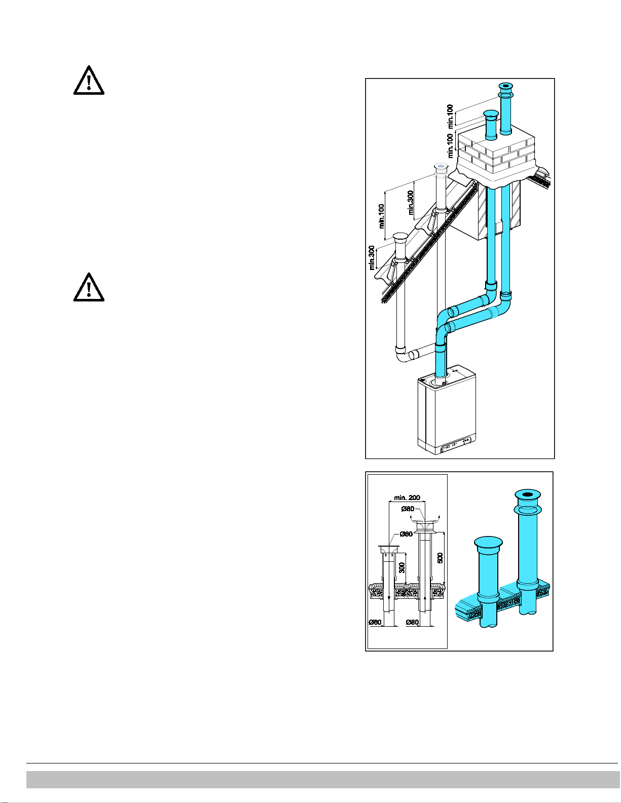
5.7.13 Concentric horizontal flue gas outlet, vertical part air-surrounded by
shaft
Unit category : C93
A flue tube system according to C93 (C33) is permitted when using the output
material provided by Daikin.
Permitted pipe length and system requirements
Air supply and combustion gas outlet pipe between unit and concentric horizontal
shaft 80/125 with a maximum length of 10 meters. The flue tube must be fitted on a
slope towards the boiler.
Flue outlet in shaft with 80 mm diameter (rigid or flexible) with a maximum length of
25 meters.
When using plastic flue tube material, a minimum temperature class of T120
applies.
The transfer bend between concentric and vertical flue connection in the shaft must
be supported in the manner instructed by Daikin.
The assembly instruction of the manufacturer of the flue tube system must always
be followed in full.
The minimum interior measurement of the shaft must be 200 x 200 mm.
In existing installations, the shaft must be inspected and if necessary cleaned before
the new installation is commissioned.
Combustion gas outlet and air supply pipe
For assembly, see par. 5.7.5 General assembly.
Note:
The outlet system is certified in combination with the unit.
Daikin Europe NV 34
Page 35

6 COMMISSIONING THE UNIT AND THE INSTALLATION
In case of a CH pressure lower than 0.5 bar, the CH
WARNING
WARNING
6.1 Filling and air purge of unit and installation
6.1.1 CH system
1. Insert the unit's plug into a socket.
The unit may carry out a self-check:
The unit will then go into the off setting:
pressure is shown on the temperature display.
pressure will be displayed flashing on the display.
In the off setting, the CH pressure will be displayed.
2. Connect the filling hose to the fill/drain tap and fill the installation with clean
drinking water, up to a pressure between 1 and 2 bar if the installation is cold
(to be read from the temperature display).
3. Aerate the system with the manual aerator (A).
Upon request, an automatic aerator can be fitted onto the unit instead of the
manual aerator.
4. Aerate the installation with the manual aerators on the radiators.
5. Top up the CH installation if the pressure has dipped too low due to the
aeration.
6. Check all couplings for leaks.
7. Check whether the siphon is filled with water.
If the siphon is not filled with water, combustion gases may be
released into the room.
If an additive is added to the CH water, it must be suitable for
the materials used in the unit, such as copper, brass, stainless
steel, steel, plastic and rubber. The additive should preferably
have a KIWA/ATA/Atest certification.
6.1.2 DHW provision
1. Open the main tap to bring the DHW section up to pressure.
2. Aerate the exchanger and the pipe system by opening a DHW tap.
Leave the tap open until all air has flowed out of the system.
3. Check all couplings for leaks.
2
(on service display).
-
(on service display) and the CH
6.1.3 Gas supply
1. Aerate the gas pipe with the initial pressure measuring nipple (D) on the gas
block.
2. Check all couplings for leaks.
3. Check the initial pressure and offset pressure (see par. 7.7).
Daikin Europe NV
35
Page 36

6.2 Commissioning the unit
Reading
Operating
1
On/off A
On/off button
2
CH operation or setting maximum CH temperature
B Tap/CH button to set the required temperature
3
Tap operation or setting tap temperature
C - button
4
Required
temperature CH or tap water in °C / pressure CH water in bar / malfunction code
D + button
5
Tap comfort function eco
E Tap comfort function off / eco / on button
6
Tap comfort function on
F Service button / actual temperature during heat request
7
Operating
code G
Reset button
8
Flashing in case of a malfunction
After the following actions have been completed, the unit may be commissioned.
1. Press the button to commission the unit.
The heat exchanger will be heated up, and on the service display, 3, 4 and 7 appear (Depending on status of external eco switch
and/or OpenTherm regulation).
2. Set the pump setting depending on the set maximum power and the water side resistance of the installation. For the water head of the
pump and the loss of pressure of the unit: (see par. 7.4).
3. Set the room thermostat higher than the room temperature. The unit will now go into CH operation:
4. Fire up the installation.
5. Check whether the set maximum CH power matches the requested value. If necessary, the maximum CH power can be adjusted (see par.
7.2 parameter c and 3 and par. 7.3)
6. Check whether the set minimum and maximum value of the pump characteristic have been set correctly (see par. 7.2 and parameter 3. and
c. and par. 7.4)
7. Switch the unit off.
8. Purge the air from the unit and the installation after cooling down (top up if necessary).
9. Switch the unit on.
10. Check the heating and the hot water provision for the correct functioning.
11. Instruct the user on the filling, air purging and functioning of the heating and the hot water provision.
Comments
•
The unit is fitted with an electronic boiler controller which ignites the boiler controller
and controls she modulating pump, at every heat request from the heating or from
the hot water provision.
•
The circulation pump will run at every heat request for the heating. The pump has a
post-running time of 1 minute. The post-running time can be changed upon request
(see par. 7.2).
•
The pump will run automatically 1 time per 24 hours, for 10 seconds, in order to
prevent it from getting stuck. This automatic switching on of the pump takes place 24
hours after the lastheating request. To change the time, the room thermostat must be
turned up for a moment at the requested time.
•
For the hot water provision, the pump will not run.
5
on the service display.
Daikin Europe NV 36
Page 37

6.3 Switching off the unit
CAUTION
Drain the unit and the installation, if the mains
electricity supply is interrupted and there is a risk of
freezing.
1. Remove the plug from the socket.
2. Drain the unit with the filling/draining tap.
3. Drain the installation at the lowest point.
4. Close the main tap of the hot and cold water supply to the unit.
5. Drain the unit by loosening the domestic hot water couplings under the unit.
6. Empty the siphon.
6.3.1 Frost protection
•
In order to prevent the condense outlet from freezing, the unit must be installed in a
frost-free room.
•
The unit is fitted with frost protection in order to prevent it from freezing. If the
temperature of the heat exchanger drops too low, the boiler will switch on until the
heat exchanger has heated up. If there is the possibility that the installation (or a
part thereof) may freeze, an (external) frost thermostat must be fitted at the coldest
place, on the return pipe. This must be connected in accordance with the electrical
diagram (see par. 10.1).
Note
If an (external) frost thermostat has been fitted on the installation and has been
connected to the unit, it will not be active if the unit on the operating panel is switched
off (
-
on service display).
Daikin Europe NV
37
Page 38

7 SETTING AND ADJUSTMENT
The functioning of the unit can be influenced by means of the (parameter) settings in the boiler
controller. Part of this can be configured directly via the operating panel, another part can only
be adjusted by means of the service code.
7.1 Direct via operating panel
The following functions can be operated directly.
Unit on/off
The button activates the unit.
When the unit is active, the green LED above the button will be lit. When the unit is
off, one bar will be lit on the service display (
electricity supply. In this operation setting, the temperature display will also show the
pressure in the CH installation (in bar).
Tap comfort
The tap comfort function can be operated with the tap comfort button and has the following
settings:
•
On: ( LED on) The tap comfort function of the unit is continuously switched on.
The heat exchanger is continuously kept warm. The unit always immediately
provides warm water.
•
Eco: ( LED on) The tap comfort function of the unit is self-learning. The unit will
adjust to the usage pattern of the domestic hot water. This means the heat
exchanger will not be kept warm during the night or during longer absences.
•
Off: (Both LEDs off.) Off: The heat exchanger is not kept warm which means the
supply of domestic hot water takes a bit of time. If there is no desire for domestic hot
water, or of immediate supply hereof, the tap comfort function can be switched off.
Resetting
Check the nature of the malfunction on the basis of the malfunction codes under par. 8.2 and if
possible, resolve the cause of the malfunction before resetting the unit.
If a locking malfunction is indicated by means of a flashing LED above the button and a
number on the display, the unit can be restarted by pressing the reset button.
Change settings of the various functions:
Pressing the button for 2 seconds, will take you to the users setting menu (LED at and the
number display will start to flash). If you press the button repeatedly, a different function LED
will flash each time. When the LED flashes, the appropriate function can be set with the and
button. The set value is displayed on the display.
The on/off button closes the settings menu and the changes are not saved.
The reset button closes the settings menu and saves the changes.
When no button is pressed for 30 seconds, the settings menu will automatically be closed and
the changes are saved.
Maximum CH leaving water temperature
Press the button until the LED at starts flashing.
Use the and button to enter the temperature between 30°C and 90°C (standard setting
80°C).
Tap water temperature
Press the button until the LED at starts flashing.
Use the and button to enter the temperature between 40°C and 65°C (standard setting
60°C).
-
) to show the unit is connected to the
Daikin Europe NV 38
Page 39

EKOMBG*AAV1
Parameter
Description
22 28 33
Settings reach
0 Service code
[15] - - - Access to installers settings, the service code must be
1 Installation
type 0 0 0 0= combi
2 CH pump setting
0 0 0 0=
pump post
-
running time active
3 Set maximum CH power
60 60 60
Setting reach set value parameter c up to 100%
3. Maximum capacity modulating CH pump
80 80 80
Setting reach set value parameter c
. up to 100%
4 Set maximum hot water power
99 99 99
Setting reach set value parameter d up to 100%
5
Min. leaving water temperature of the fuel
25 25 25 Setting reach 10°C to set value parameter 5
5. Max setting value leaving water
90 90 90 Setting reach 30°C to 90°C
6
Min.
outdoor
temperature of the fuel line
-7 -7 -7 Setting reach
-
9 to 10°C
7
Max.
outdoor
temperature of the fuel line
25 25 25
Setting reach 15°C to 30°C
8
CH pump post
-
running time after CH
1 1 1 Setting reach 0 to 15 minutes
9 CH pump post
-
running time after boiler
1 1 1 Setting reach 0 to 15 minutes (n/a to Combi unit)
A Setting three
-
way valve or electrical valve
0 0 0
0= powered during CH operation
7.2 Parameter settings via the service code
The parameters of the boiler controller have been configured in the factory in accordance with the following
table.
These parameters can only be changed with the service code. Take the following actions to
activate the program memory:
1. Press the and the button simultaneously, until a
2. Use the button to enter
3. Use the button to set the parameter you wish to configure, on the service display.
4. Use the and button to set the parameter to the required value (visible) on the temperature display.
5. After all the required changes have been entered, press the button until
The boiler controller has now been reprogrammed.
Note
Pressing the button will take you out of the menu without saving the parameter changes.
Example: Change maximum CH power
1. Press the and the button simultaneously.
2. Use the button to go to
3. Press the button 3 x. 60 and 3 will appear on the display.
4. Use the button to change the 60 to 70.
5. Press the button until
6. The change has now been implemented. The maximum CH power has been increased from 60 to 70 %.
15
(service code) on the temperature display.
15
.
P
appears.
0
appears on the service display and a
P
appears on the service display.
entered (=15)
1= Solo EKOMBG22AAV1 + boiler
2= Tap (hot water only)
3= Solo
0
on the temperature display.
line
temperature via operating panel
operation
operation
1= pump continuously active
2= not applicable
3= not applicable
(100 % = 99 + 1x )
1= powered during hot water operation and rest
2= powered during every heat request (CH, hot water and
continuous heating function)
3= group regulation
4= External DHW tank pump
Daikin Europe NV
39
Page 40

5= Powered during CH demand and rest
b Booster
0 0 0
0= off
C Step-by-step modulation
1 1 1
0= step
-by-
step modulation off during CH operation
c
Minimum rpm CH
30 30 30
Setting reach 20 to 50%
c. Minimum capacity modulating CH pump
40 40 40
Setting reach 15 to set value par. 3.
d Minimum
rpm hot water
25 25 25
Setting reach 20 to 50%
E Min. leaving water temperature at OT
(OpenTherm) or RF thermostat
40 40 40 Setting reach 10°C to 60°C
E . Reaction OT and RF room thermostat
1 1 1
0= do not respond to hot water request if requested
F
Start rpm CH
70 60 50
Settings reach 50 to 99% of the set maximum rpm
F . Minimum start rpm hot water
70 60 50
Settings reach 50 to 99% of the set maximum rpm
h
Max. rpm fan
50 50 50
Setting reach 40 to 50 (40=4000 rpm, 50=5000 rpm).
n Regulated temperature during boiler
80 80 80 Setting reach 60°C to 90°C
n. Hot water temperature at Comfort/Eco
0 0 0
Setting reach 0 or 40°C to 60°C
O. Wait time CH request response
0 0 0
Settings reach 0
– 15 minutes
o Waiting time CH operation after hot water
0 0 0 Settings reach 0 to 15 minutes
o. Number of eco days
3 3 3 Setting reach
0 to 10
P Anti-recycling time during CH operation
5 5 5
Minimum switch off time on boiler water temperature
P. Reference value hot water
24 30 36
24 = EKOMBG22AAV1
6= Powered during hot water operation
1= on
1= step-by-step modulation on during CH operation
2= Power control by Open Therm room thermostat
enabled
temperature is lower than the set value par. E
1= respond to hot water request with minimum leaving
water temperature limited to set value par. E
2= respond to hot water request with maximum leaving
water temperature (on/off function)
Please note: Factory setting, rpm may deviate
operation (Ta)
0 = reheating temperature is equal to hot water
temperature
operation
0 = Comfort function controllable by Open Therm room
thermostat
1 – 10 number of eco days
Can be set to 0 to 15 minutes
30 = EKOMBG28AAV1
36 = EKOMBG33AAV1
Daikin Europe NV 40
Page 41

Desired CH power in kW (approx.)
Settings on service display
EKOMBG*AAV1
(in % maximum rpm)
22 28 33
22.7 28.4 31.9 100
20.5 25.6 28.8 90
18.2 22.9 25.6 80
16.0 20.1 22.4 70
13.7 17.4 19.2 60
11.5 14.6 16.0 50
9.3 11.8 12.8 40
5.9 7.7 8.0 25
The
minimum feedthrough amount (l/h)
Set power (kW)
155 5.4 kW
240 8.5 kW
510 17.8 kW
750 26.2 kW
7.3 Setting maximum CH power
The maximum CH power is set to 60% in the factory. If more power is required for the
CH installation, the maximum CH power can be changed by adjusting the rpm of the
fan. See table: Setting CH power.
This table shows the relation between the rpm of the fan and the unit power.
Caution:
The power is slowly increased when the fire is lit and is lowered when the set leaving
water temperature is reached (modulation on Tsupply).
7.4 Set pump capacity
The EKOMBG*AAV1 CH boilers are fitted with a modulating A-class pump which
modulates on the basis to the CH power provided. The minimum and maximum
capacity of the pump can be adjusted with the parameters 3 and c. Also see par. 7.2.
The set value of parameter 3. (max. pump setting) is the percentage of the maximum
pump capacity and is linked to the set maximum CH power as set with parameter 3
The set value of parameter c. (min. pump setting) is linked to the minimum CH-power
as set with parameter c
If the CH load modulates between the minimum and maximum value, the pump
capacity will modulate along proportionately.
Pressure loss graph unit CH side
A. EKOMBG22AAV1
B. EKOMBG28AAV1
C. EKOMBG33AAV1
7.5 Weather dependent regulation
When connecting an outdoor sensor, the leaving water temperature is automatically
regulated dependent on the outdoor temperature, in accordance with the set fuel line.
The maximum leaving water temperature (Tmax) is set via the temperature display. If
so desired, the fuel line can be changed by using the service code (see par.7.2). The
weather dependent regulation only functions with an on-off thermometer. When
applying an Open Therm room thermostat, the outside temperature is passed on, but
the fuel line of the CH boiler is not active.
Fuel line graph
X. T outside in °C
Y. T leaving water in °C
A. Factory setting
(Tmax CH = 80°C, Tmin CH = 25°C, Tmin ex = -7°C, Tmax ex = 25°C)
B. Example
(Tmax CH = 60°C, Tmin CH = 25°C, Tmin ex = -7°C, Tmax ex = 25°C)
Daikin Europe NV
41
Page 42

7.6 Conversion to different type of gas
CAUTION
a certified installer.
CAUTION
Gas type
Natural gas
Propane P
Gas category
2E/H G20 3P / G31
CO2 % at Low setting (L)
( and )
See par.
See par.
CO2 % at Low setting (H)
( and
2x
)
See par.
See par.
Initial gas pressure (mBar)
20 mBar
30/37/50 mBar
Gas dosing ring
Natural gas
Propane P
Work on gas carrying parts may only be carried out by
If a unit is connected to a different type of gas than the one it has been set to by the
manufacturer, the gas dosing ring must be replaced. Conversion sets for other types of gas are
available to order.
Converting the dosing ring
1. Switch off the boiler and remove the plug from the socket.
2. Shut the gas valve.
3. Remove the front panel from the unit.
4. Loosen the coupling (A) above the gas block and turn the gas mixing tube (B) backwards.
5. Replace the O-ring (C) and the gas dosing ring (D) by the rings in the conversion set.
6. Reassemble it in reverse order.
7. Open the gas valve.
8. Check whether the gas couplings before the gas block are sealed.
9. Enter the plug in the socket and switch on the boiler.
10. Check whether the gas couplings after the gas block are sealed (during operation).
11. Now check the setting of the gas/air ratio (see par. 7.7).
12. Put a sticker of the configured gas type on top of the existing sticker at the gas block.
13. Put a sticker of the configured gas type at the type plate.
14. Return the front panel onto the unit.
7.7 Gas/air regulation
The gas/air regulation has been set at the factory and does not require any
adjustments, in principle.
The setting can be checked by measuring the CO2 percentage in the combustion gases or by
measuring the offset.
In case of any disturbance, replacement of the gas block or conversion to a different type of
gas, the regulation must be checked and set in accordance with the following tables.
L
With open cover
Error!
Reference
source not
found.
With open cover
Error!
Reference
source not
found.
(only valid in combination with fan with integrated
L
tunnel venturi (see drawing )
EKOMBG22AAV1 505 410
EKOMBG28AAV1 600 480
EKOMBG33AAV1 655 525
CO2 check must be carried out with open cover. If the cover is
shut, the CO2 % may be higher than the values stated in the
above table.
Error!
Reference
source not
found.
Error!
Reference
source not
found.
Daikin Europe NV 42
Page 43

IMPORTANT
IMPORTANT
CO2
value at
Natural gas
Natural gas G25
Propane G31
Propane G31
Maximum value
9.6 8.3 10.8
Minimum value
8.4 7.3 9.8
IMPORTANT
percentage when the test program is being
CO2
value at
Natural gas
Natural gas G25
Propane G31
Propane G31
Maximum value
(a)
Minimum value
8.4 7.4 9.4 9.4
7.8 Setting gas/air regulation
The CO2 setting has been set at the factory and does not require any adjustments, in principle.
The setting can be checked by measuring the CO2 percentage in the combustion gases. In case
of any disturbance of the setting, the replacement of the gas valve or the conversion to a
different type of gas must be checked, and if necessary set in accordance with the following
instructions. Always check the CO2 percentage when the lid is open.
Checking the carbon dioxide setting
1 Switch off the gas boiler with the button.
2 Remove the front panel from the gas boiler.
3 Remove the sample point (a) and enter an appropriate chimney analysis probe.
Ensure the start-up procedure of the analysis machine has been
completed before inserting the probe in the sample point.
Wait for the gas boiler to run stable. Faulty measurements may
occur if the measuring probe is connected before the boiler is
running stable. We recommend you wait for at least 30 minutes.
4 Switch on the gas boiler with the button and create a request for space heating.
5 Select the High setting by twice pressing the and buttons simultaneously. A capital
letter "H" will appear on the service display. The user display will show a Busy symbol. Do
NOT carry out a test when a small letter "h" is shown. If this is the case, press and
again.
6 Allow the display values to stabilize. Wait at least 3 minutes and compare the CO2
percentage to the values in the following table.
maximum power
7 Note the CO2 percentage at maximum power. This is important in relation to the following
steps.
G20
-
appears on the service display.
(in Belgium)
(30/50 mbar)
(37 mbar)
It is NOT possible to adjust the CO2
carried out. If the CO2 percentage deviates from the values in the above table,
contact your local service department.
8 Select the Low setting by once pressing the and buttons simultaneously. "L"
appears on the service display. The user display will show a Busy symbol.
9 Allow the display values to stabilize. Wait at least 3 minutes and
compare the CO2 percentage to the values in the following table.
minimum power
(a) CO2 value at maximum power registered at setting High.
Daikin Europe NV
G20
(in Belgium)
(30/50 mbar)
(37 mbar)
43
Page 44

10 If the CO2 percentage at maximum and minimum power is within the reach stated in
CAUTION
IMPORTANT
Measured value at
Set values CO
(%) at minimum power (front lid open)
Natural gas 2H (G20, 20 mbar)
Propane 3P
10.8 - 10.5±0.1
10.6 10.3±0.1
10.4 10.1±0.1
10.2 9.9±0.1
10 9.8±0.1
9.8 9.6±0.1
9.6 9.0±0.1
-
9.4 8.9±0.1
9.2 8.8±0.1
9.0 8.7±0.1
8.8 8.6±0.1
8.6 8.5±0.1
03010102
A
B
the above tables, the CO2 setting of the boiler is correct. If NOT, adjust the CO2
setting in accordance with the instruction in the following chapter.
11 Switch off the unit by pressing the button and return the sample point to its
position. Make sure it is gas tight.
12 Return the front panel to its place.
Work on gas carrying parts may ONLY
be carried out by qualified, competent
individuals.
Adjusting the carbon dioxide setting
Only adjust the CO2 setting when you have first checked it and you have made
sure the adjustment is necessary. No adjustments may be made to the gas
valve without prior permission from your
local Daikin distributor. In Belgium, the gas valve may NOT be adjusted and/or
the seal may NOT be removed or broken. Contact your distributor.
1 Remove the cap (A) which covers the adjuster screw.
2 Turn the screw (B) to the right to increase the CO2 percentage, and to the left
to decrease it. See the following table for the desired value.
maximum power
2
(G31,30/50/37 mbar)
3 After measuring the CO2 percentage and adjusting the setting, replace the
cover cap and the sample point. Make sure they are gas tight.
4 Select the High setting by twice pressing the and buttons
simultaneously. A capital letter will appear on the service display.
5 Measure the CO2 percentage. If the CO2 percentage still deviates from the values
in the table which indicates the CO2 percentage at maximum power, contact
your local distributor.
6 Press + and - simultaneously to leave the test program.
7 Return the front panel to its place.
Daikin Europe NV 44
Page 45

8 MALFUNCTIONS
Temperature display
Description
Possible cause/solution
• Unit is off.
10, 11, 12, 13, 14
Sensor fault
S1
• Air in the installation. Purge the air from the boiler and CH installation.
20, 21, 22, 23, 24
Sensor fault S2
• Check wiring for break.
0 Sensor
fault after self
-
check
• Replace S1 and/or S2.
1 Temperature too high
• Air in installation. Purge the air from the boiler and CH installation.
2 Switch S1 and S2
• Check cable harness.
4 No flame signal
• Main gas valve
not opened
.
5 Poor flame signal
• Condense output blocked.
6 Flame detection error
• Replace ignition cable + spark plug.
8 Fan rpm is not correct
• Fan is coming up against cover insulation.
27 Short circuit
outdoor
sensor
29, 30
Gas valve
controller
fault
• Replace
boiler controller
.
Only replace faulty parts with the original Daikin parts.
8.1 Show last malfunction
Use the key to switch the unit off, and press the button.
The red malfunction LED is lit continuously, and the latest fault code is shown flashing on the temperature display.
If the unit has never detected a locking malfunction, no code will be displayed.
The last locking malfunction can be deleted by briefly pressing the button while pressing the button.
8.2 Malfunction codes
If the malfunction LED is flashing, the boiler controller detects a fault. A malfunction code will be shown on the temperature display.
When the malfunction is rectified, the boiler controller can be restarted by pressing the reset button.
The following faults can be distinguished:
•
Check the connection of the ntc on the hot water tube.
•
Check wiring for break.
•
Replace S1.
•
Replace S2.
•
Pump is not running. Reset or replace the pump, see par. 8.2.10
•
Replace S1 or S2.
•
Gas supply pressure too low, or disappears.
•
Condense output blocked.
•
Check ignition unit and ignition cable.
•
No or incorrect ignition distance, check this using the checking mold.
•
Gas block or ignition unit is not receiving electrical current.
•
Check earthing.
•
Gas supply pressure too low, or disappears.
•
Check ignition unit and ignition cable.
•
Check setting of gas block.
•
Check earthing.
•
Check air supply and gas output for possible recirculation of flue gases.
•
Replace ignition unit.
•
Replace boiler controller.
•
Wiring between fan and cover.
•
Check wiring or plug for lack of wire contact, measure 25-27V dc.
•
Check and/or replace fan.
•
Replace boiler controller.
• Check the wiring of the outdoor sensor.
• Replace outdoor sensor.
Boiler controller is not suitable for this application.
Replace boiler controller for the appropriate version.
Failing to fit or incorrectly fitting the sensors S1 and/or S2 may lead to serious damage.
Daikin Europe NV
45
Page 46

8.2.1 Boiler controller is noisy when igniting
Possible causes:
Solution:
Gas supply
pressure too high.
Yes
The home pressure controller may be faulty. Contact the energy company.
No
Check the ignition pin distance with the checking mold.
No
Gas/air regulation not correctly configured.
Yes
Check the setting, see Gas air regulation par.
7.7 and par. 7.8.
No
Check the ignition pin distance with the checking mold.
Possible causes:
Solution:
Gas supply
pressure too low. Lower than 20
No
Recirculation combustion gases.
Yes
Check the combustion gas outlet and the air supply system.
No
Gas/air regulation not configured correctly.
Yes
Check the setting, see Gas air regulation par.
7.7 and par. 7.8.
No
Boiler controller
gasket faulty.
Yes
Replace the
boiler controller
gasket.
No
Boiler controller
faulty. Yes
Replace the
boiler controller
.
Possible causes:
Solution:
The service display shows nothing.
Yes
Check whether the plug is in the socket.
No
The
service display shows nothing.
Yes
Check the fuse, see Electrical diagram par. 10.1
No
boiler is off.
No
Check the wiring.
No
Check the electricity supply.
Incorrect ignition distance. Yes
Weak spark. Yes
Checking mold ignition pin position
8.2.2 Boiler controller resonates
mbar.
Yes The home pressure controller may be faulty. Contact the energy company.
Replace the ignition pin.
Check and/or replace ignition cable.
Replace the ignition unit on the gas block. Replace the ignition pin.
Pin must touch mold Pin must not touch mold
8.2.3 No heating (CH)
The service display shows a hyphen (
Room thermostat/weather dependent regulation
not connected or faulty.
Pump is not running. Display shows 80 and 1. Yes
Daikin Europe NV 46
-
). The
Yes
Yes
Switch on the boiler with the button.
Check OpenTherm, On/off connection of the unit, or the connection between CH
boiler and RF room thermostat .Replace the thermostat.
Replace the weather-dependent regulation.
Check connector X2 and X4..
Page 47

No
No electrical supply (24 V). Yes
Replace the faulty
controller
. Check the wiring in accordance with the diagram.
Replace the faulty
controller
.
Possible causes:
Solution:
Clean the unit and siphon.
Possible causes:
Solution:
Water pressure in installation is too low.
Yes
Top up the installation. See par. 6.1.1.
No
Room thermostat is not set correctly.
Yes
Check the setting and adjust if required.
No
Increase the CH temperature See Operation CH. If there is an
outdoor
sensor:
No
Check the ∆T (± 20° C) between the supply and
return CH. Ensure there is good
No
The boiler power is not set correctly.
Yes
Adjust the boiler power. See Setting maximum CH power.
No
No heat transfer due to contamination in the CH
Possible causes:
Solution:
The service display shows nothing.
Yes
Check whether the plug is in the socket.
No
The service display shows nothing.
Yes
Check the
fuse, see Electrical diagram par. 10.1
No
Flow sensor does not work.
Yes
Replace the flow sensor.
No
Tap flow <
1.5 l/min. Yes
Increase the tap flow.
No
No electricity supply on flow sensor (5V DC).
Yes
Check the wiring in
accordance with the diagram.
No
S3 faulty.
Yes
Replace S3.
No
The thermostatic tap only lets through cold water. This means the tap flow through
Possible causes:
Solution:
Reduce the tap flow. Check the dosing disk (EKOMBG22AAV1 and
No
DHW temperature set too low.
Yes
Increase the
DHW temperature, see par. 7.1.
Unwanted circulation in the ch circuit during hot water request due to thermosiphon
No
Insufficient heat transfer due to lime scale or
Yes
Remove lime scale or rinse the CH boiler on the tap water side.
8.2.4 The power is reduced
Check the connector X4.
At high rpm, the power has decreased. Yes
8.2.5 CH is not reaching correct temperature
Temperature is set too low. Yes
No flow through the installation. Yes
boiler/installation.
Yes Rinse the CH boiler/installation on the side of the CH.
8.2.6 No domestic hot water
Check the flue tube and the air supply system.
Check the outdoor sensor for short circuit: rectify this.
flow through the installation.
The thermostatic shower or bath tap is faulty. Yes
8.2.7 DHW is not reaching the correct temperature
Tap flow too high. Yes
CH installation becomes hot during tapping. Yes
Daikin Europe NV
the boiler remains under 1.5 l/min. Check the thermostatic tap.
EKOMBG28AAV1)
effect or second pump in the CH circuit. Install a check valve in case of
thermosiphon effect or a two-way valve in case of a second pump.
47
Page 48

contamination in the CH boiler on the tap water
side.
Possible causes:
Solution:
Check the wiring.
Replace the weather
-
dependent r
egulation.
No
Unwanted circulation in the CH circuit due to thermosiphon effect or second pump in
Possible causes:
Solution:
Too high or too low mains voltage.
Yes
Check the mains voltage.
No
Pump temperature is too high.
Yes
Check the water and ambient temperature.
Possible causes:
Solution:
Reset the pump by switching off the unit by pressing the on/off button for at least 20
8.2.8 CH installation stays warm unwanted
Room thermostat/weather dependent regulation
faulty or short circuited.
CH installation is heated due to Tap comfort.
The service display regularly shows code 7.
Yes
Yes
Check OpenTherm, On/off connection of the unit, or the connection between CH
boiler and RF room thermostat. Replace the thermostat.
the CH circuit. Install a check valve in case of thermosiphon effect or a two-way
valve in case of a second pump.
8.2.9 A-label pump LED flashes intermittently red/green
8.2.10 A-label pump LED flashes red
Pump stopped. Yes
seconds (attention: if the pump has been set to continuous, the pump can only
be reset by pulling the plug from the socket).
Replace the pump.
Daikin Europe NV 48
Page 49

9 MAINTENANCE
CAUTION
CAUTION
contain ceramic fibers.
The unit and the installation must be checked by a certified installer, and cleaned if
necessary.
Work on gas carrying parts may only be carried out by a certified
installer.
After work, check the flue gas carrying parts for air tightness.
If the unit has just been operational, some parts may be hot.
.
9.1.1 Disassembly
1. Switch the unit off with the button.
2. Remove the plug from the socket.
3. Shut the gas valve.
4. Open the display valve and loosen the two screws on the left and right of the
display, and remove the front panel.
5. Wait until the unit has cooled down.
6. Unscrew the coupling nut at the bottom of the flue tube to the left.
7. Slide the flue gas pipe upwards (1) with a turn to the left until the bottom of the pipe
reaches above the coupling of the condense outlet container. Pull the bottom of the
pipe forward (2) and remove the pipe by rotating it to the left and down (3).
8. Lift the condense outlet tray from the connection of the siphon (4) on the left, and
turn it to the right with the siphon connection over the edge of the bottom tray (5).
Push down the condense outlet tray at the back from the connection to the heat
exchanger (6) and remove it from the unit.
9. Take the connector from the fan and the ignition unit from the gas block.
10. Disconnect the coupling under the gas block.
11. Unscrew the shouldered bolts (hex key) of the front lid and remove it to the front,
complete with gas block and fan (be careful not to damage the boiler controller,
insulation plate, gas block, gas pipe and fan). Lay the removed front lid with the foot
rests horizontally on a flat surface.
12. The boiler controller and the integrated insulation plate do not require any
maintenance (do not need cleaning). Therefore never use a brush or compressed
air to clean these parts, in order to avoid dust developing.
9.1.2 Cleaning
1. Clean the heat exchanger with a brush or vacuum cleaner, from top to bottom.
2. Clean the bottom of the heat exchanger.
3. Clean the condense outlet tray with water.
4. Clean the siphon with water.
5. Only clean the bottom of the front plate.
Daikin Europe NV
The ï
ntegrated insulation plate and
boiler controller
gasket
49
Page 50

9.1.3 Fitting
When assembling, check the various seals for damages, hardening,
03010078
03010083
1
2
3
4
5
6
7
8
9
10
11
(hairline) fractures and/or discoloration. Where necessary, place a
new seal. Also check the correct positioning.
1. Check that between the flange of the shoulder bolt and the front plate, there is a
thin layer of ceramic grease.
If there is no or insufficient grease, it must be applied (see image).
2. Check whether the seal around the front lid has been fitted correctly. Place the
front lid on the heat exchanger and secure it with the special shoulder bolts (hex
key). Evenly tighten the shoulder bolts crosswise manually (10 – 12 Nm). For the
sequence of tightening, see image.
3. Evenly manually tighten the boiler controller bolts crosswise.
4. Fit the gas coupling under the gas block.
5. Fit the connector onto the fan and the ignition unit onto the gas block.
6. Fit the condense outlet tray by sliding it into the outlet stump of the switcher (1), with the
siphon connection, before the bottom tray. Then turn the condense outlet tray to the left (2)
and push it down into the siphon connection (3). Make sure that the rear of the condense
outlet tray ends up resting on the cam at the back of the bottom container (A).
7. Fill the siphon with water and fit it onto the connection under the condense outlet tray.
8. Slide the flue gas pipe, while turning it to the left, with its top around the flue gas adapter in
the top lid. Insert the bottom into the condense outlet tray, drag the gasket down and
tighten the swivel head to the right.
9. Open the gas valve and check the gas couplings under the gas block and on the assembly
bracket for leakage.
10. Check the CH and the water pipes for leakage.
11. Insert the plug into the socket.
12. Switch the unit on with the button.
13. Check the front lid, the connection of the fan to the front lid and the flue tube parts for leaks.
14. Check the gas-air regulation (see par. 7.7 and par. 7.8) and check the gas coupling on the
gas block for gas tightness.
15. Assemble the cover and tighten the two screws to the left and the right of the display, and
close the display cover.
16. Check the heating and the hot water provision for correct functioning.
Daikin Europe NV 50
Page 51

10 TECHNICAL SPECIFICATIONS
Unit category
C13; C 33; C43; C53; C63; C83: C93
Initial gas
pressure
G20 –
20 mbar; G31 : 30 mbar
Suitable for gas
II2H3+
Technical data
EKOMBG*AAV1
22 28 33
Domestic water
Nom. load upper value
kW
6.1 –
25.9 8.0 –
32.3 8.3 –
36.3
Nom. load lower value
kW 5.6 – 23.3 7.1 –
29.1 7.6 –
32.7
Nom. out
put kW 5.9 –
22.7 7.7 –
28.4 8.2 –
32.1
Domestic water threshold
l/min 2
Domestic water quantity 60°C
l/min 6 7.5 9
Domestic water quantity 40°C (mixed)
l/min 10 12.5 15
Domestic water temperature
°C 60
Effective unit wait time*
sec <1
Domestic water side pressure difference
kPa See par.
5.2
CH
Nom. load upper value**
kW
6.1 –
25.9 8.0 –
32.3 8.3 –
36.3
Nom. load lower
value**
kW 5.6 – 23.3 7.1 –
29.1 7.6 –
32.7
Nom.
out
put kW
5.9 –
22.7 7.7 –
28.4 8.2 –
32.1
Max. CH water pressure
bar 3
Max. CH water temperature
°C 90
Other data
Gas consumption (G25)
m3/h 0.67 –
2.80 0.85 –
3.50 0.91 –
3.93
Gas
consumption (G20)
m3/h 0.58 –
2.42 0.74 –
3.02 0.79 –
3.39
Gas consumption (G31)
m3/h 0.22 –
0.92 0.28 –
1.15 0.30 –
1.29
Pressure loss of the unit (CH)
mWk
See par.
7.4
Electrical data
Mains voltage
V 230
Safety class
IP IP44
Absorbed power: full load
W 80
Absorbed power: part load
W 40
Absorbed power: standby
W 2
Installation
measurements and weight
Height
mm
590 650 710
Width mm
450
Depth mm
240
Weight
kg 30 33 36
* Time needed from beginning of draining in order to achieve a temperature increase of 40K to the hot water outlet of the
device based on the CW-hot water flow.
** Maximum CH power is set at the factory at 60% of the highest value (see par. 7.3 Setting CH power).
Daikin Europe NV
51
Page 52

10.1 Electrical diagram
A Earth connection heat exchanger
F
Fuse (3.15 AT)
P1
CH pump
S5
Flow sensor
B
Spark cover
G
Gas valve + ignition
unit
S1
Supply sensor
S7
CH water pressure sensor
C Boiler controller
I
Ignition/ionization pin
S2
Return sensor
V
Fan
E
Earth lips
boiler controller
M
Mains voltage
S3
DHW sensor
Connecting:
Connector X4
Floor heating or group regulation valve. (3=L (brown), 5=switch (black), 6=N (blue))
Three-way valve (3=L (brown), 5=switch (black), 6=N (blue)) (VC4013 Honeywell
24V=
6 - 7
8 - 9
9 - 10
11 - 12
Connector X2
230V
~
7 - 8
3 – 5 - 6
3 – 5 - 6
Connector X5
5 -
CH pump (5= PWM signal (red), E=earth)
On/off room thermostat and/or frost thermostat (24Vdc or ± 125mA)
Outdoor sensor (12 k Ohm / 25°C)
Tank sensor or tank thermostat (if through connection 9 – 10 present, then remove it)
OpenTherm thermostat
2 - 4
Mains cable (2=L (brown), 4=N (blue), E=earth)
CH-pump (8=L (brown), 7=N (blue), E=earth)
(VC4013 Honeywell 230V~).
230V~).
Computer interface
Daikin Europe NV 52
Page 53

NTC 12k Ohm
T [°C]
R [ohm]
T [°C]
R [ohm]
T [°C]
R [ohm]
-15
76020
25
12000
65
2752
-10
58880
30
9805 70 2337
-5
45950
35
8055 75 1994
0 36130
40
6653 80 1707
5 28600
45
5522 85 1467
10 22800
50
4609 90 1266
15 18300
55
3863 95 1096
20 14770
60
3253 100 952
10.2 NTC resistances
Daikin Europe NV
53
Page 54

11 WARRANTY CONDITIONS
If the unit is due for replacement, it can usually be taken
The general warranty conditions of Daikin Europe NV apply to
this product.
The warranty is void if it is determined that the faults,
damages, or undue wear are attributable to improper use or
inexpert treatment or inexpert repair, setting, installation or
maintenance, by non-certified installers, or that it was exposed to
substances with aggressive chemicals (incl. hair spray) and other
damaging substances.
The warranty also becomes void when pipes and couplings have
been applied in the installation which may cause oxygen diffusion,
or the defect is a consequence of lime scale (damaging to the unit
and installation). Surface damage as well as transport damage is
included under the warranty. The entitlement to warranty becomes
void if it cannot be proven that the CH boiler has been subjected to
maintenance by a certified installer at least once a year from the
commissioning date. The instructions for installation and use which
we provide for units must be followed in full.
Environment
back by your dealer, following consultation. Should this not
be possible, consult your council for the possibilities for
recycling or environmentally friendly processing of used
materials.
Various plastics and metals were used in the manufacturing
of the unit. Furthermore, the unit contains electrical
components which belong with electronic waste.
Use as intended
The unit, as described in this documentation is intended for heating
spaces via a central heating installation and/or the supply of hot water.
Any other usage falls outside the intended use of the unit. No liability
can be accepted on damage arising from incorrect use.
Daikin Europe NV 54
Page 55

Page 56

885507
4P374378-1A
 Loading...