

Daikin EHS04P30A, EHSB04P30A, EHS08P30A, EHSB08P30A, EHS08P50A Installation manuals
...
Installation and maintenance
instructions
Indoor unit for air-water-heat pumps
Daikin Altherma integrated solar unit
Daikin Altherma
EHS(X/H)04P30A
EHS(X/H)B04P30A
EHS(X/H)08P30A
EHS(X/H)B08P30A
EHS(X/H)08P50A
EHS(X/H)B08P50A
EHS(X/H)16P50A
EHS(X/H)B16P50A
Installation and maintenance instructions
Daikin Altherma integrated solar unit
English

List of contents
1 Safety . . . . . . . . . . . . . . . . . . . . . . . . . . . . . . 3
1.1 Observing instructions . . . . . . . . . . . . . . . . . . . . 3
1.2 Warning signs and explanation of symbols . . . . 3
1.2.1 Meaning of the warnings. . . . . . . . . . . . . . . . . . . . .3
1.2.2 Validity. . . . . . . . . . . . . . . . . . . . . . . . . . . . . . . . . . .3
1.2.3 Handling instructions. . . . . . . . . . . . . . . . . . . . . . . .3
1.3 Avoid danger . . . . . . . . . . . . . . . . . . . . . . . . . . . 4
1.4 Intended use . . . . . . . . . . . . . . . . . . . . . . . . . . . 4
1.5 Instructions for operating safety . . . . . . . . . . . . . 4
1.5.1 Before working on the hydraulic system . . . . . . . . .4
1.5.2 Electrical installation . . . . . . . . . . . . . . . . . . . . . . . .4
1.5.3 Working on cooling systems (heat pump) . . . . . . . .4
1.5.4 Site of installation . . . . . . . . . . . . . . . . . . . . . . . . . .5
1.5.5 Heating system and sanitary connection . . . . . . . .5
1.5.6 Requirements for the heating water . . . . . . . . . . . .5
1.5.7 Operation . . . . . . . . . . . . . . . . . . . . . . . . . . . . . . . .5
1.5.8 Instructing the user/owner. . . . . . . . . . . . . . . . . . . .5
2 Product description. . . . . . . . . . . . . . . . . . . 6
2.1 Design and components . . . . . . . . . . . . . . . . . . 6
2.1.1 Top of unit. . . . . . . . . . . . . . . . . . . . . . . . . . . . . . . .6
2.1.2 Device external and internal design Daikin
Altherma EHS(X/H)...P30A . . . . . . . . . . . . . . . . . . .7
2.1.3 Device external and internal design Daikin
Altherma EHS(X/H)B...P30A. . . . . . . . . . . . . . . . . .8
2.1.4 Device external and internal design Daikin
Altherma EHS(X/H)...P50A . . . . . . . . . . . . . . . . . . .9
2.1.5 Device external and internal design Daikin
Altherma EHS(X/H)B...P50A. . . . . . . . . . . . . . . . .10
3 Set-up and installation . . . . . . . . . . . . . . . 12
3.1 Dimensions and connections . . . . . . . . . . . . . . 12
3.1.1 Daikin Altherma EHS(X/H)...P30A . . . . . . . . . . . .12
3.1.2 Daikin Altherma EHS(X/H)...P50A . . . . . . . . . . . .13
3.1.3 Scope of delivery. . . . . . . . . . . . . . . . . . . . . . . . . .13
3.2 Set-up . . . . . . . . . . . . . . . . . . . . . . . . . . . . . . . 14
3.3 Water connection . . . . . . . . . . . . . . . . . . . . . . . 15
3.3.1 Connecting hydraulic lines . . . . . . . . . . . . . . . . . .16
3.4 Electrical connection . . . . . . . . . . . . . . . . . . . . 16
3.4.1 Overall connection plan Daikin Altherma
EHS(X/H) . . . . . . . . . . . . . . . . . . . . . . . . . . . . . . .17
3.4.2 Position of the circuit boards. . . . . . . . . . . . . . . . .18
3.4.3 Connection assignment, circuit board A1P . . . . . .18
3.4.4 Terminal assignment for the RTX-AL4 circuit
board. . . . . . . . . . . . . . . . . . . . . . . . . . . . . . . . . . .18
3.4.5 Terminal assignment for the RTX-EHS circuit
board. . . . . . . . . . . . . . . . . . . . . . . . . . . . . . . . . . .18
3.4.6 Connection assignment, circuit board
RoCon BM1. . . . . . . . . . . . . . . . . . . . . . . . . . . . . .19
3.4.7 Mains connection Daikin Altherma EHS(X/H). . . .19
3.4.8 Removing the protective cover . . . . . . . . . . . . . . .19
3.4.9 Opening the control housing and establishing
electrical connections . . . . . . . . . . . . . . . . . . . . . .20
3.4.10 Connection of ERLQ exterior heat pump unit . . . .20
3.4.11 Connection of external temperature sensor
RoCon OT1. . . . . . . . . . . . . . . . . . . . . . . . . . . . . .20
3.4.12 Connection of an external switching contact. . . . .21
3.4.13 External demand signal (EDS) . . . . . . . . . . . . . . .21
3.4.14 Connection of the electrical Daikin backup heater
(EKBUxx) . . . . . . . . . . . . . . . . . . . . . . . . . . . . . . .22
3.4.15 Connection of the Daikin room thermostat . . . . . .22
3.4.16 Connection of the Daikin room controller
EHS157034. . . . . . . . . . . . . . . . . . . . . . . . . . . . . .23
3.4.17 Connection of Daikin mixer module EHS157068 .23
3.4.18 Internet gateway Daikin EHS157056 . . . . . . . . . .23
3.4.19 Connection of the Daikin FWXV(15/20)AVEB. . . .23
3.4.20 Connection of the switching contact
(AUX output) . . . . . . . . . . . . . . . . . . . . . . . . . . . . .24
3.4.21 Low tariff mains connection (HT/NT). . . . . . . . . . 24
3.4.22 Connection intelligent controller
(Smart Grid - SG) . . . . . . . . . . . . . . . . . . . . . . . . 25
3.4.23 Symbols and legend keys on connection and
circuit diagrams . . . . . . . . . . . . . . . . . . . . . . . . . . 25
3.5 Laying coolant lines. . . . . . . . . . . . . . . . . . . . . 26
3.6 Pressure test and filling the coolant circuit . . . 27
3.7 Filling the system with water . . . . . . . . . . . . . . 27
3.7.1 Checking the water quality and adjusting the
pressure gauge . . . . . . . . . . . . . . . . . . . . . . . . . . 27
3.7.2 Filling the hot water heat exchanger . . . . . . . . . . 27
3.7.3 Filling the storage tank . . . . . . . . . . . . . . . . . . . . 27
3.7.4 Filling the heating system . . . . . . . . . . . . . . . . . . 27
4 Start-up. . . . . . . . . . . . . . . . . . . . . . . . . . . . .28
4.1 Initial start-up. . . . . . . . . . . . . . . . . . . . . . . . . . 28
4.1.1 Requirements . . . . . . . . . . . . . . . . . . . . . . . . . . . 28
4.1.2 Start-up . . . . . . . . . . . . . . . . . . . . . . . . . . . . . . . . 28
4.1.3 Set the commissioning parameters. . . . . . . . . . . 28
4.1.4 Venting the internal heating circulation pump . . . 30
4.1.5 Activating the parameter [Air Purge] . . . . . . . . . . 30
4.1.6 Check minimum flow . . . . . . . . . . . . . . . . . . . . . . 30
4.1.7 Configuring Screed Program parameters
(only if necessary) . . . . . . . . . . . . . . . . . . . . . . . . 30
4.2 Re-commissioning. . . . . . . . . . . . . . . . . . . . . . 31
4.2.1 Requirements . . . . . . . . . . . . . . . . . . . . . . . . . . . 31
4.2.2 Start-up . . . . . . . . . . . . . . . . . . . . . . . . . . . . . . . . 31
5 Decommissioning . . . . . . . . . . . . . . . . . . . .32
5.1 Temporary shutdown . . . . . . . . . . . . . . . . . . . 32
5.1.1 Draining the storage tank . . . . . . . . . . . . . . . . . . 32
5.1.2 Draining the heating circuit and hot water circuit. 33
5.2 Final shutdown . . . . . . . . . . . . . . . . . . . . . . . . 34
6 Service and maintenance . . . . . . . . . . . . . .35
6.1 General . . . . . . . . . . . . . . . . . . . . . . . . . . . . . . 35
6.2 Removing the protective cover . . . . . . . . . . . . 35
6.3 Activities to be performed annually . . . . . . . . . 35
6.4 Filling and topping up the storage tank . . . . . . 37
6.5 Filling and topping up the heating system. . . . 38
7 Errors, malfunctions and messages . . . . .39
7.1 Deleting errors, correcting malfunctions,
deleting messages . . . . . . . . . . . . . . . . . . . . . 39
7.1.1 Current fault display . . . . . . . . . . . . . . . . . . . . . . 39
7.1.2 Read Protocol . . . . . . . . . . . . . . . . . . . . . . . . . . . 39
7.1.3 Troubleshooting. . . . . . . . . . . . . . . . . . . . . . . . . . 39
7.2 Malfunctions . . . . . . . . . . . . . . . . . . . . . . . . . . 40
7.3 Fault codes . . . . . . . . . . . . . . . . . . . . . . . . . . . 44
7.4 Monitoring and configuration DIP Switch . . . . 50
7.5 Emergency operation . . . . . . . . . . . . . . . . . . . 51
8 Hydraulic system connection. . . . . . . . . . .52
9 Technical data . . . . . . . . . . . . . . . . . . . . . . .55
9.1 Equipment data . . . . . . . . . . . . . . . . . . . . . . . . 55
9.1.1 Daikin Altherma EHS(X/H)...P30A . . . . . . . . . . . 55
9.1.2 Daikin Altherma EHS(X/H)...P50A . . . . . . . . . . . 57
9.2 Characteristic lines . . . . . . . . . . . . . . . . . . . . . 58
9.2.1 Sensor characteristic lines . . . . . . . . . . . . . . . . . 58
9.2.2 Characteristic curves for pumps . . . . . . . . . . . . . 60
9.3 Tightening torque . . . . . . . . . . . . . . . . . . . . . . 60
9.4 Circuit diagram Daikin Altherma EHS(X/H). . . 61
10 List of keywords . . . . . . . . . . . . . . . . . . . . .62
11 Notes. . . . . . . . . . . . . . . . . . . . . . . . . . . . . . .63
Installation and maintenance instructions
2
Daikin Altherma EHS(X/H)
Daikin Altherma integrated solar unit
008.1420744 – 08/2014
1Safety
1 x Safety
1.1 Observing instructions
These instructions are a >> Translation of the original
version
Please read this manual carefully and thoroughly before proceeding with the installation or modification of the heating
system.
These instructions are aimed at people who are authorised and
who have successfully completed a qualifying technical or skilled
manual training program for the particular work to be carried out
and who have participated in a professional development
seminar held by the appropriate responsible authority. This, in
particular, includes heating specialists and climate control techni
cians who have experience, as a result of their technical training
and their knowledge of the subject, of proper and appropriate installation and maintenance of heating, climate control and
cooling installations and heat pumps.
This manual provides all the necessary information for installation, start-up and maintenance, as well as basic information on
operation and settings. All parameters needed for trouble-free
operation have been configured at the factory. Please go through
the attached documents for a detailed description of operation
and control.
<< in your language.
Relevant documents
– Daikin Altherma EHS(X/H):
– Operating instructions for the user/owner
– Commissioning checklist
– Operating instructions for the RoCon HP control unit
– External unit for Daikin Altherma EHS(X/H); the associated
installation and operating instructions.
– When connecting to a Daikin solar system; the associated
installation and operating instructions.
– If a Daikin FWXV(15/20)AVEB is connected; the associated
installation and operating instructions.
– In the case of connection to a control component offered as
an accessory (room controller, mixer module etc.); the asso-
ciated installation and operating instructions.
The guides are included in the scope of supply for the individual
units.
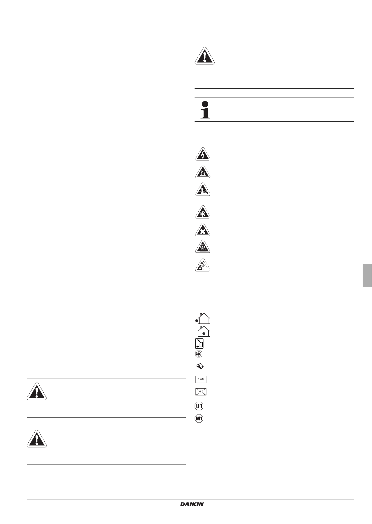
1.2 Warning signs and explanation of symbols
1.2.1 Meaning of the warnings
Warnings in this manual are classified according into their severity and probability of occurrence.
DANGER!
Draws attention to imminent danger.
Disregarding this warning can lead to serious injury or
death.
CAUTION!
Indicates a situation which may cause possible
damage.
Disregarding this warning can lead to damage to
property and the environment.
This symbol identifies user tips and particularly useful
information, but not warnings or hazards.
-
Special warning signs
Some types of danger are represented by special symbols:
Electric power
Risk of burning or scalding
Risk of environmental damage
Danger of local freezing up
Health impairing or irritant materials
Prescribed temperature for continuous use
Danger of explosion
1.2.2 Validity
Some information in this manual has limited validity. The validity
is highlighted by a symbol.
Heat pump exterior unit ERLQ
Heat pump interior unit EHS(X/H)
FWXV(15/20)AVEB
Only valid for Daikin Altherma EHS(X/H) with cooling
function (see also section
Pay attention to the stipulated tightening torque (see
chapter 9.3 "Tightening torque")
Only applicable for the unpressurised system (Drain
Back)
Only applicable for the pressurised system
Valid/available only if a room regulator is connected
Valid/available only if a mixer module is connected
1.4)
WARNING!
Indicates a potentially dangerous situation.
Disregarding this warning can result in serious injury
or death.
Daikin Altherma EHS(X/H)
Daikin Altherma integrated solar unit
008.1420744 – 08/2014
1.2.3 Handling instructions
● Instructions on actions are shown as a list. Actions of which
the sequential order must be maintained are numbered.
Installation and maintenance instructions
3
1 x Safety
Results of actions are identified with an arrow.
Entry into a setting procedure
Exit from a setting procedure
1.3 Avoid danger
The Daikin Altherma EHS(X/H) is state-of-the-art and is built to
meet all recognised technical requirements. However, improper
use may result in serious physical injuries or death, as well as
property damage.
To prevent such risks, install and operate Daikin Altherma
EHS(X/H) only:
– as stipulated and in perfect condition,
– with an awareness of the safety and hazards involved.
This assumes knowledge and use of the contents of this manual,
the relevant accident prevention regulations and the recognised
safety-related and occupational medical rules.
WARNING!
This unit is not intended for use by persons (including
children) with impaired physical, sensory or mental
faculties or persons with insufficient experience and/or
expertise unless supervised by a person responsible
for ensuring their safety or are given instruction by this
person on how to use the unit.
Use as intended also involves compliance with maintenance and
inspection conditions. Spare parts must at least satisfy the technical requirements defined by the manufacturer. This is the case,
for example, with original spare parts.
1.5 Instructions for operating safety
1.5.1 Before working on the hydraulic system
● Work on the Daikin Altherma EHS(X/H) (such as setup,
servicing, connection and initial start-up) is only to be carried
out by persons who are authorised and who have success
fully completed qualifying technical or vocational training and
who have taken part in advanced training sessions recog
nised by the appropriate responsible authorities. This, in
particular, includes heating specialists and climate control
technicians who have experience, as a result of their
technical training and their knowledge of the subject, of
proper and appropriate installation and maintenance of
heating, climate control and cooling installations and heat
pumps.
● Switch off the external main switch before starting any work
on the Daikin Altherma EHS(X/H) and secure it against
unintentional switch-on.
● Seals must not be damaged or removed.
● Make sure that the safety valves comply with the require-
ments of EN 12828 when connecting on the heating side, and
with the requirements of EN
domestic water side.
● Only original Daikin replacement parts may be used.
12897 when connecting on the
-
-
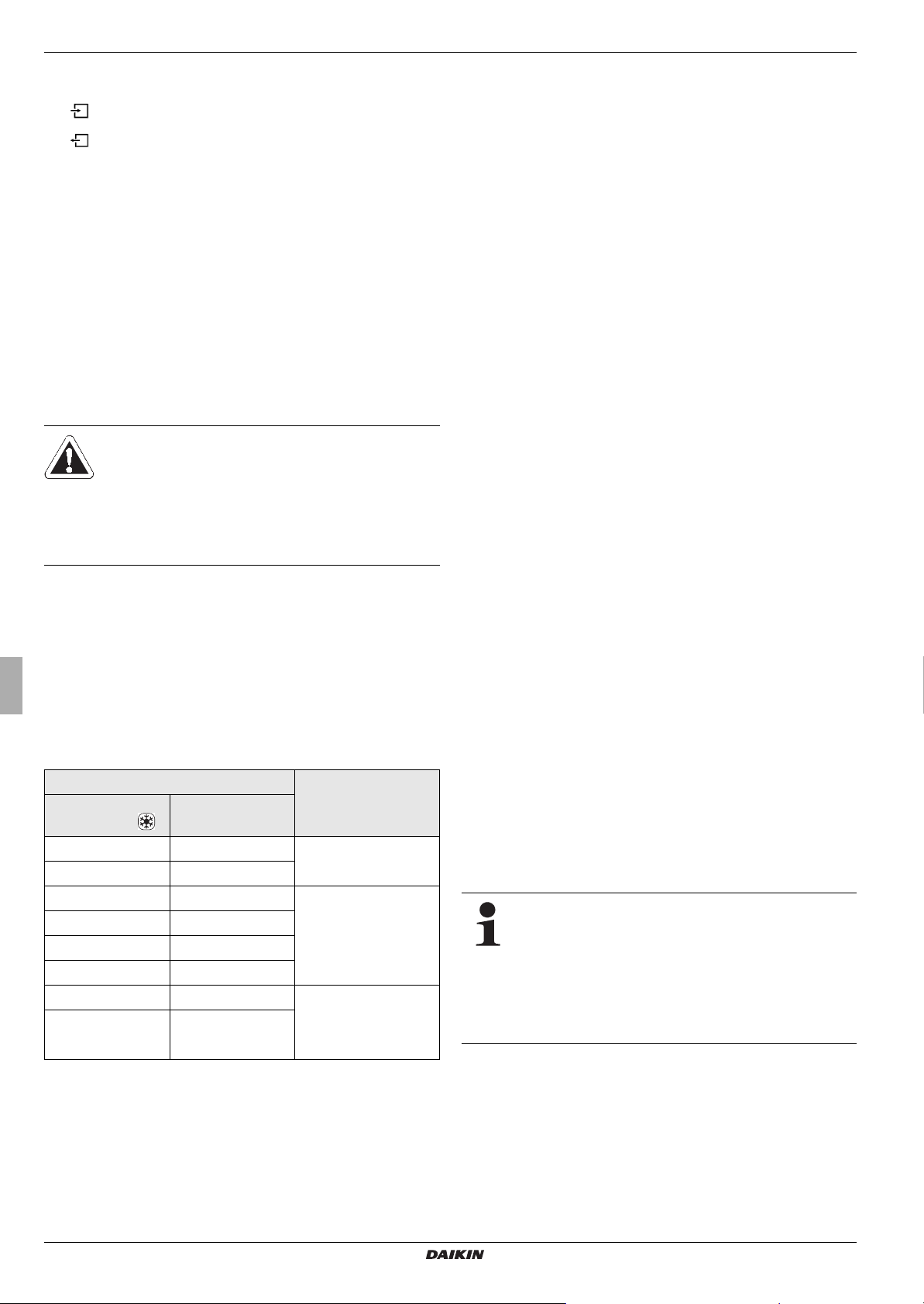
1.4 Intended use
The Daikin Altherma EHS(X/H) may only be used for preparation
of warm water, as a room heating system, and depending on its
design, as a room cooling system. The Daikin Altherma
EHS(X/H) must be installed, connected and operated only ac
cording to the indications in this manual.
Only use of a suitable external unit approved by Daikin is permitted. The following combinations are permissible in this respect:
Internal unit External unit
Heating and
cooling (X)
EHSX04P30A EHSH04P30A
EHSXB04P30A EHSHB04P30A
EHSX08P30A EHSH08P30A
EHSXB08P30A EHSHB08P30A
EHSX08P50A EHSH08P50A
EHSXB08P50A EHSHB08P50A
EHSX16P50A EHSH16P50A ERLQ011CA(V3/W1)
EHSXB16P50A
B - Additional heat exchanger for the bivalent connection
Tab. 1 -1 Permissible combinations of Daikin exterior heat pump units
and Daikin Altherma EHS(X/H) internal units
Any other use outside the intended use is considered as improper. The operator alone shall bear responsibility for any resulting damage.
Heating only (H)
EHSHB16P50A
ERLQ004CAV3
ERLQ006CAV3
ERLQ008CAV3
ERLQ014CA(V3/W1)
ERLQ016CA(V3/W1)
-
1.5.2 Electrical installation
● Electrical installation may be carried out only by electrical
engineers and in compliance with the valid electro-technical
guidelines as well as the regulations of the relevant energy
supply company (EVU).
● Compare the mains voltage (~230 V, 50 Hz or ~400 V, 50 Hz)
indicated on the type plate with the supply voltage before
connecting to the mains.
● Before beginning work on live parts, disconnect all of the
systems circuits from the power supply (switch off main
switch, disconnect fuse) and secure against unintentional
restart.
● Equipment covers and service panels must be replaced as
soon as the work is completed.
1.5.3 Working on cooling systems (heat pump)
For work on stationary refrigeration systems (heat
pumps) and air conditioning systems, proof of expertise
is required in the European Community according to
the F-Gases Directive (EC) No. 303/2008.
–Up to 3 kg coolant fill quantity: Expert certificate
category II
–3 kg coolant fill quantity or over: Expert certifi-
cate category I
● Always wear safety goggles and protective gloves.
● When working on the coolant circuit, ensure that the
workplace is well ventilated.
● Never carry out work on the coolant circuit in closed rooms or
work pits.
● Do not let coolant come into contact with open fire, embers or
hot objects.
● Never allow coolant to escape into the atmosphere (high
pressure at the point of the leak).
Installation and maintenance instructions
4
Daikin Altherma EHS(X/H)
Daikin Altherma integrated solar unit
008.1420744 – 08/2014

1 x Safety
● When removing the service pipes from the filling connections,
never hold the connections in the direction of your body.
Residual coolant could escape.
● Components and spare parts must at least satisfy the
technical requirements defined by the manufacturer.
1.5.4 Site of installation
For safe and fault-free operation, it is necessary that the installation location of the Daikin Altherma EHS(X/H) fulfils certain criteria. Related information can be found in chapter 3.2.
Information on the installation site of other components can be
found in the associated documentation supplied with them.
1.5.5 Heating system and sanitary connection
● Create a heating system according to the safety requirements
12828.
of EN
● With sanitary connection, you must observe;
–EN 1717 - Protection of domestic water from contamina-
tion in domestic water installations and general requirements concerning safety equipment for the prevention of
domestic water contamination by back-flow
–EN 806 - Technical regulations for domestic water instal-
lations (TRWI)
– And, in addition, the country-specific legal regulations
1.5.7 Operation
The Daikin Altherma EHS(X/H):
● Do not operate until all installation and connection work is
completed.
● Only operate with a completely full storage tank (Level
indicator) and heating circuit.
● Operate at a maximum pressure of 3 bar.
● Only connect with a pressure reducer on the external water
supply (supply line).
● Only operate the with the specified quantity of coolant and the
type of coolant specified.
● Only operate if the protective cover is installed.
The specified servicing intervals should be adhered to and inspection work must be carried out.
1.5.8 Instructing the user/owner
● Before you hand over the Daikin Altherma EHS(X/H), explain
to the user/owner how to operate and check the system.
● Hand over the technical documentation (this document and
all supporting documents) to the user and advise him that
these documents must be made available at all times and be
stored in the immediate vicinity of the unit.
The connection of a solar installation, an electric heating rod or
an alternative heat generator may cause the storage temperature
to exceed 60
°C.
● For this reason you should fit scalding protection
(e.g. VTA32 + screw connection set 1") during installation.
If the Daikin Altherma EHS(X/H) is connected to a heating system
with steel pipes, radiators or non-diffusion-proof floor heating
pipes, slurry and swarf could enter the hot water storage tank and
cause blockages, local overheating or corrosion.
● To prevent possible damage, fit a dirt filter or sludge
separator into the heating return flow of the system.
– SAS 1
1.5.6 Requirements for the heating water
Observe the current technological regulations to prevent corrosion products and deposits.
Minimum requirements regarding the quality of filling and supplementary water:
– Water hardness (calcium and magnesium, calculated as
calcium carbonate): ≤
– Conductivity: ≤ 2700 μS/cm
– Chloride: ≤ 250 mg/l
– Sulphate: ≤ 250 mg/l
– pH value (heating water): 6,5 - 8,5
3 mmol/l
Using filling water and top-up water which does not meet the
stated quality requirements can cause a considerably reduced
service life of the equipment. The responsibility for this lies solely
with the operator.
Daikin Altherma EHS(X/H)
Daikin Altherma integrated solar unit
008.1420744 – 08/2014
Installation and maintenance instructions
5
2 x Product description
2 Product description
2.1 Design and components
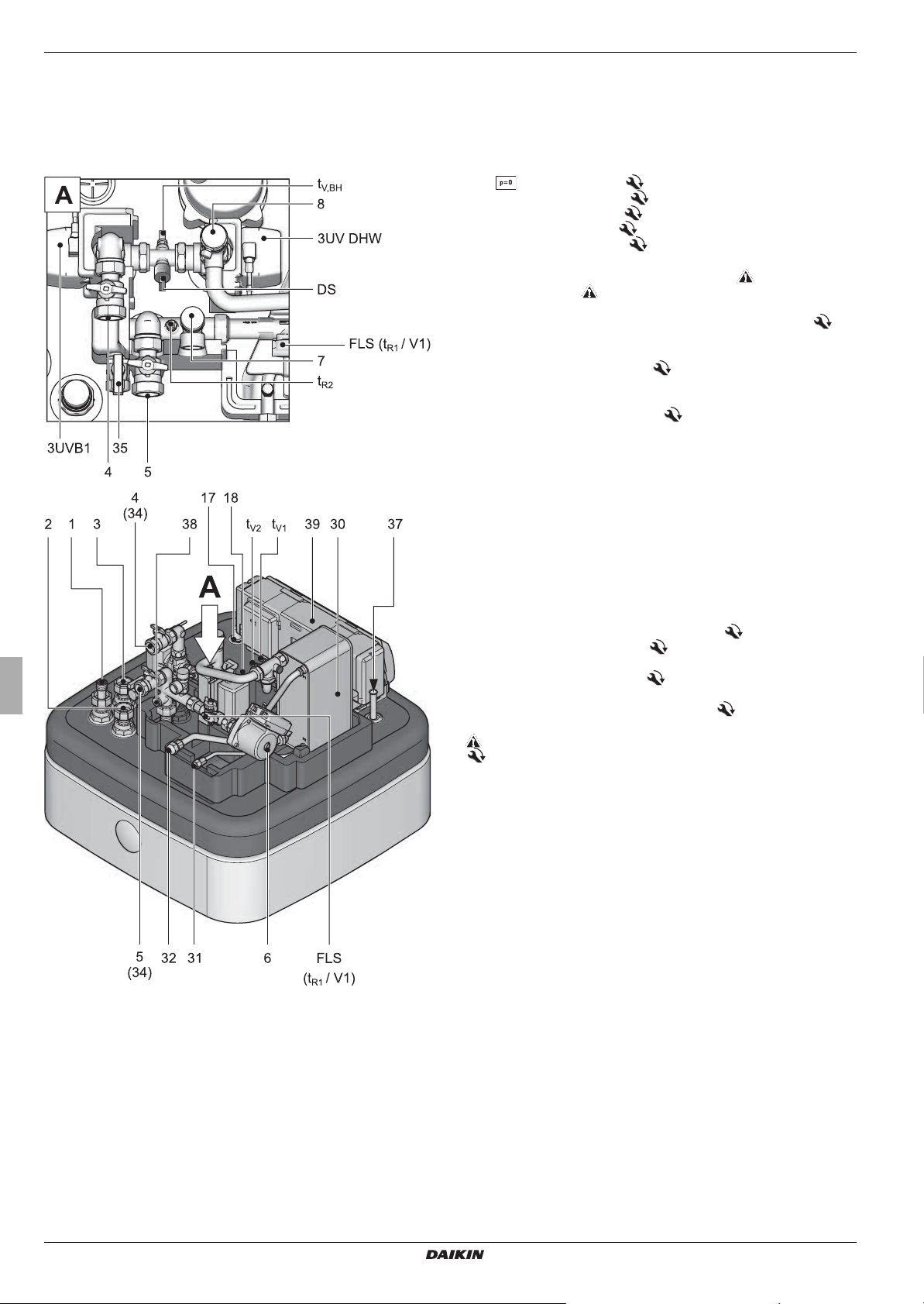
2.1.1 Top of unit
1 Solar - flow (1" IG)
2 Cold water flow (1" AG)
3 Hot water flow (1" AG)
4 Heating flow (1" AG)*
5 Heating return (1" AG)*
6 Circulation pump
7 Safety-pressure relief valve (heating circuit)
8 Automatic vent
17 Fill level indicator (tank water)
18 Daikin connection for electrical backup heater (R 1½" IG)
(Accessory)
30 Plate heat exchanger (PWT)
31 Connection coolant fluid line
Daikin Altherma EHS(X/H) 04P30A/08PxxA: Cu Ø 6.4 mm (1/4"),
Daikin Altherma EHS(X/H) 16P50A: Cu Ø 9.5 mm (3/8")
32 Connection to coolant gas line
Cu Ø 15,9 mm (5/8")
34 Ball cock (heating circuit)
35 Combined filling and draining valve (heating circuit)
37 Storage tank temperature sensor t
38 Connection diaphragm expansion vessel
DHW1
and t
DHW2
39 Controller housing with elect. terminal strip
3UVB1
3-way diverter valve (internal heat generator circuit)
3UV DHW
3-way diverter valve (hot water/heating)
DS pressure sensor
FLS (t
/ V1)
R1
Return flow temperature and flow sensor
tR2Return temperature sensor
t
V1, tV2
Feed temperature sensors
t
V, BH
Flow temperature sensor backup heater
Safety devices
Observe tightening torque!
AG Male thread
IG Female thread
* Ball cock (1" IG) is supplied with the equipment
Fig. 2-1 Structure and components Daikin Altherma EHS(X/H)
(top of unit)
Installation and maintenance instructions
6
Daikin Altherma EHS(X/H)
Daikin Altherma integrated solar unit
008.1420744 – 08/2014
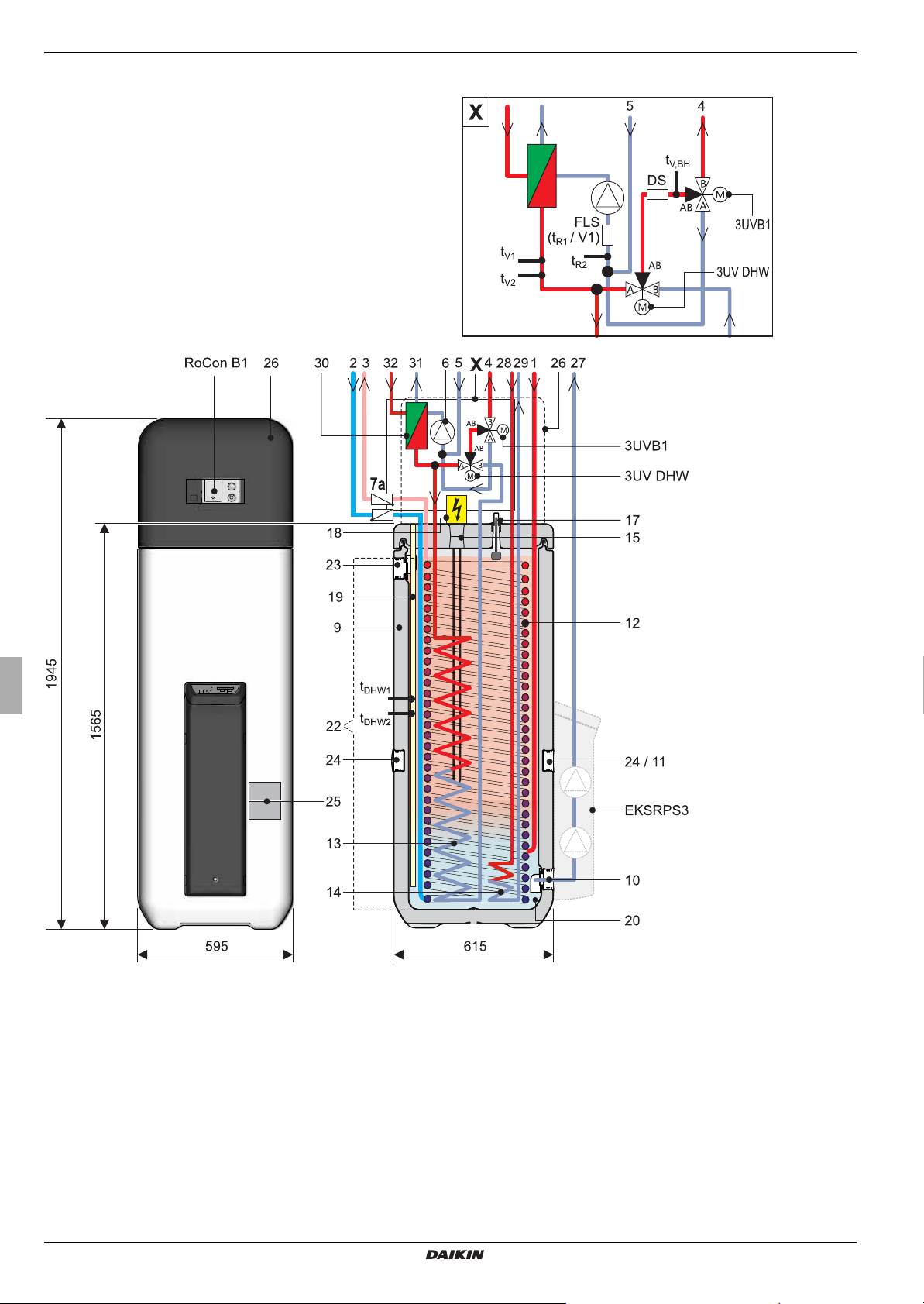
2.1.2 Device external and internal design Daikin Altherma EHS(X/H)...P30A
2 x Product description
Fig. 2-2 Design and components of the Daikin Altherma EHS(X/H)...P30A (external view and internal design)
Daikin Altherma EHS(X/H)
Daikin Altherma integrated solar unit
008.1420744 – 08/2014
For legend descriptions see tab. 2 -1
Installation and maintenance instructions
7
2 x Product description
2.1.3 Device external and internal design Daikin Altherma EHS(X/H)B...P30A
Fig. 2-3 Design and components of the Daikin Altherma EHS(X/H)B...P30A (external view and internal design)
For legend descriptions see tab. 2 -1
Installation and maintenance instructions
8
Daikin Altherma EHS(X/H)
Daikin Altherma integrated solar unit
008.1420744 – 08/2014
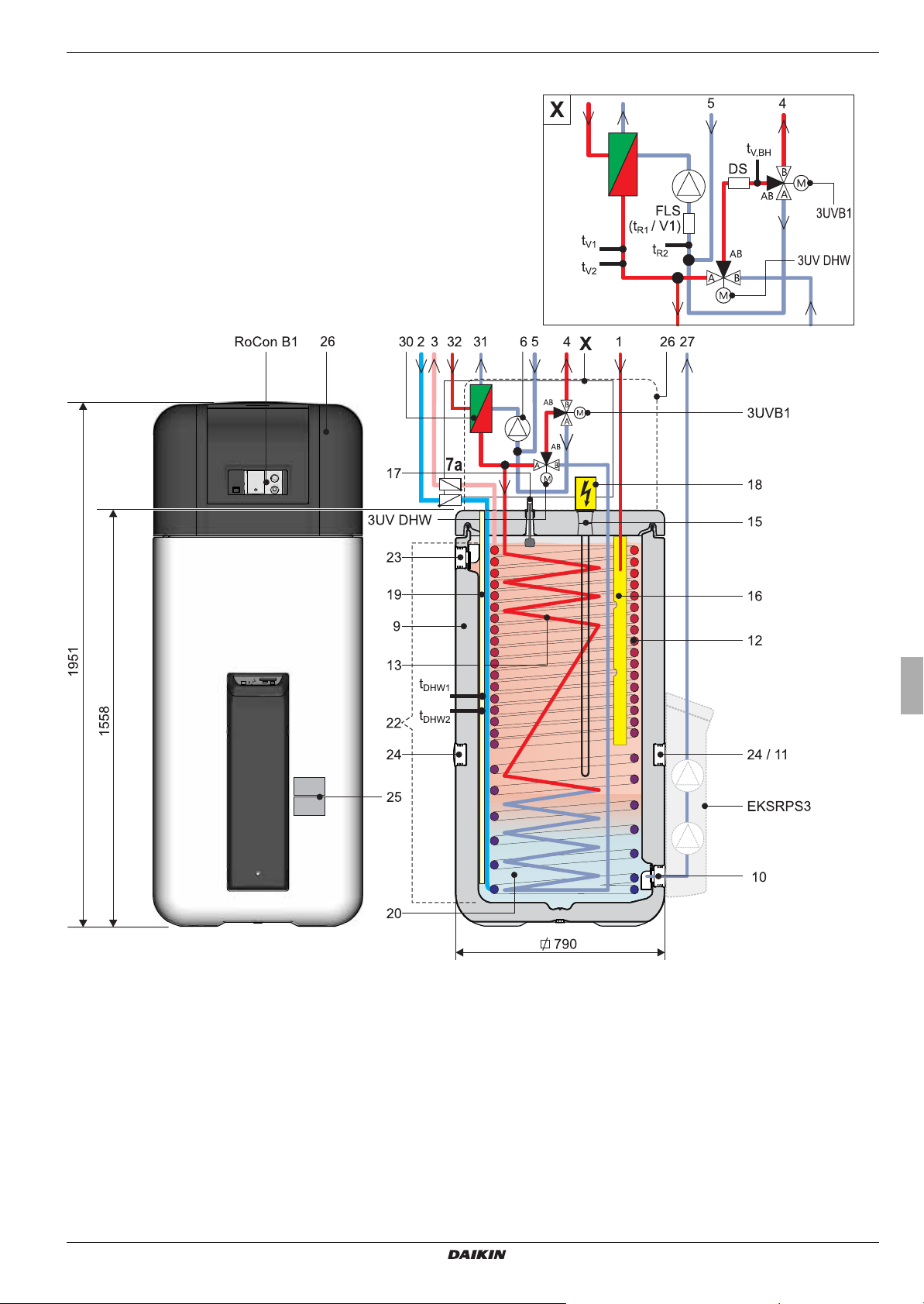
2.1.4 Device external and internal design Daikin Altherma EHS(X/H)...P50A
2 x Product description
Fig. 2-4 Design and components of the Daikin Altherma EHS(X/H)...P50A (external view and internal design)
For legend descriptions see tab. 2 -1
Daikin Altherma EHS(X/H)
Daikin Altherma integrated solar unit
008.1420744 – 08/2014
Installation and maintenance instructions
9
2 x Product description
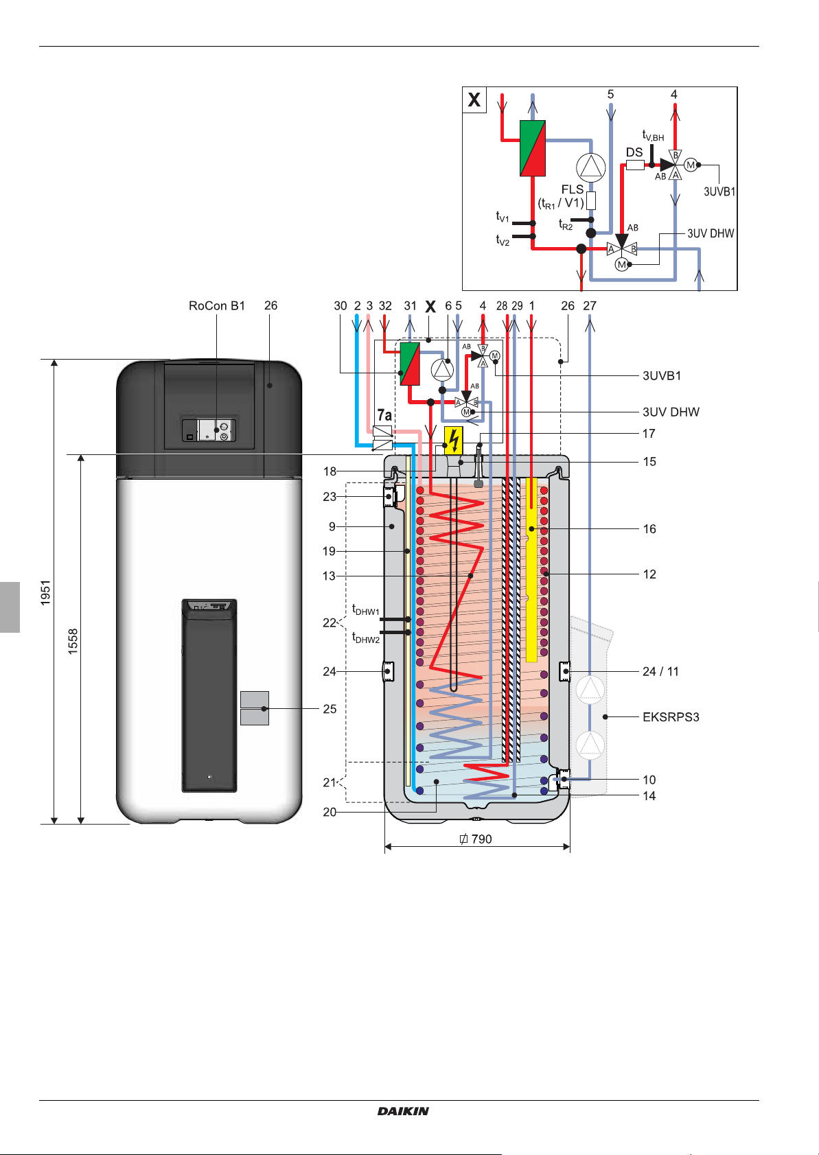
2.1.5 Device external and internal design Daikin Altherma EHS(X/H)B...P50A
Fig. 2-5 Design and components of the Daikin Altherma EHS(X/H)B...P50A (external view and internal design)
For legend descriptions see tab. 2 -1
Installation and maintenance instructions
10
Daikin Altherma EHS(X/H)
Daikin Altherma integrated solar unit
008.1420744 – 08/2014
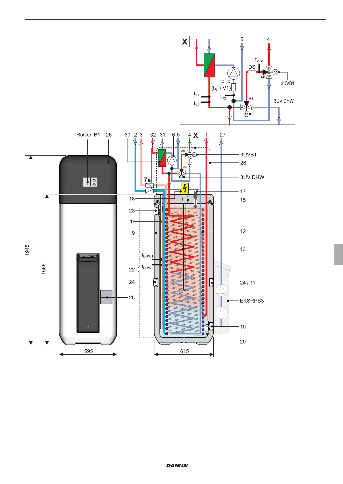
2 x Product description
1 Solar - flow or connection for addition-
al heat source(1" IG)
2 Cold water flow (1" AG)
3 Hot water flow (1" AG)
4 Heating flow (1" AG)*
5 Heating return (1" AG)*
6 Circulation pump
7a Recommended accessories:
Non-return valves (2 pcs.)
9 Storage tank (double walled jacket made
of polypropylene with PUR hard foam heat
insulation)
10 Filling and drainage connection or
Solar - return flow connection
11 Mount for solar R3 controller or handle
12 Heat exchanger (stainless steel) for drink-
ing water heating
13 Heat exchanger (stainless steel) for stor-
age tank charging or heating support
14 Heat exchanger (stainless steel) for pres-
surised solar storage tank charging
15 Connection for optional electrical backup
heater (R 1½" IG)
16 Solar inflow layering pipe
17 Fill level indicator (tank water)
18 Optional: Electrical backup heater (BUxx)
19 Submersible sensor sleeve for storage
tank temperature sensor t
20 Unpressurised storage tank water
DHW1
and t
DHW2
21 Solar zone
22 Hot water zone
23 Safety overflow connection
24 Mount for handle
25 Type plate
26 Protective cover
27 Solar - return
28 Solar - flow (3/4" IG)
(only type Daikin Altherma EHS(X/H)B)
29 Solar - return flow (3/4" IG)
(only type Daikin Altherma EHS(X/H)B)
30 Panel heat exchanger
31 Liquid-side coolant connection
Daikin Altherma EHS(X/H)
...04P30A/08PxxA:
Cu Ø 6.4 mm (1/4"),
Daikin Altherma EHS(X/H)...16P50A:
Cu Ø 9.5 mm (3/8")
32 Connection to coolant gas line
Cu Ø 15,9 mm (5/8")
3UVB1
3-way diverter valve (internal heat genera-
tor circuit)
3UV DHW
3 way diverter valve (hot water/heating)
DS Pressure sensor
FLS (t
t
/ V1)
R1
Return flow temperature and flow sensor
, t
DHW1
DHW2
Storage tank temperature sensor
tR2Return temperature sensor
t
V1, tV2
Feed temperature sensors
t
V, BH
Flow temperature sensor backup
heater
RoCon B1
Operating section Daikin Altherma
EHS(X/H) control unit
EKSRPS3B
Optional: Daikin R3 solar control and
pump unit
Safety devices
Observe tightening torque!
AG Male thread
IG Female thread
* Ball cock (1" IG) is supplied with the equip-
ment
Tab. 2 -1 Legend from fig 2-2 to fig 2-5
Daikin Altherma EHS(X/H)
Daikin Altherma integrated solar unit
008.1420744 – 08/2014
Installation and maintenance instructions
11
3 x Set-up and installation
3 Set-up and installation
WARNUNG
Cooling systems (heating pumps), climate control systems and heating devices that have been set up and installed incorrectly can both endanger life and health of people and be impaired in their function.
● Work on the Daikin Altherma EHS(X/H) (such as setup, servicing, connection and initial start-up) is only to be carried
out by persons who are authorised and who have successfully completed qualifying technical or vocational training
and who have taken part in advanced training sessions recognised by the relevant responsible authorities. These
include in particular certified heating engineers, qualified electricians and HVAC specialists, who because of their
professional training and expert knowledge, have experience in the professional installation and maintenance of
heating, cooling and air conditioning systems and heat pumps.
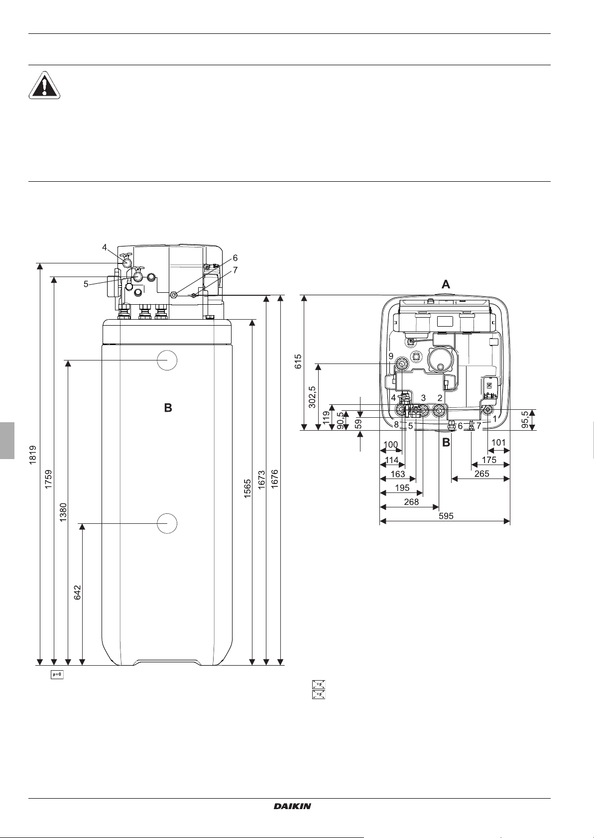
3.1 Dimensions and connections
3.1.1 Daikin Altherma EHS(X/H)...P30A
1 Solar - feed
2Cold water
3 Hot water
4 Heating feed
5 Heating return flow
6 Connection coolant gas line
Fig. 3-1 Connections and dimensions Daikin Altherma EHS(X/H)...P30A (general)
Installation and maintenance instructions
7 Connection coolant fluid line
8 Solar - feed flow (only Daikin Altherma EHS(X/H)(B) type)
9 Solar - return (only Daikin Altherma EHS(X/H)(B) type)
A Front
BBack
12
Daikin Altherma EHS(X/H)
Daikin Altherma integrated solar unit
008.1420744 – 08/2014
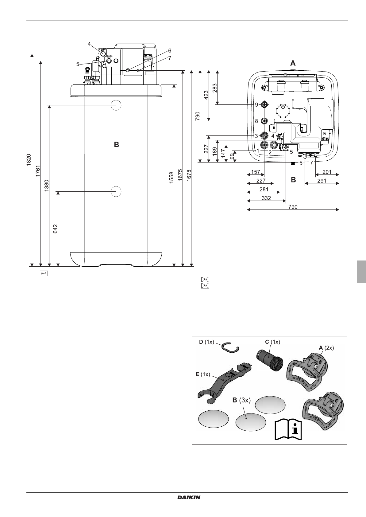
3.1.2 Daikin Altherma EHS(X/H)...P50A
3 x Set-up and installation
1 Solar - feed
2 Cold water
3 Hot water
4 Heating feed
5 Heating return flow
6 Connection coolant gas line
Fig. 3-2 Connections and dimensions Daikin Altherma EHS(X/H)...P50A (general)
7 Connection coolant fluid line
8 Solar - feed flow (only Daikin Altherma EHS(X/H)B type)
9 Solar - return (only Daikin Altherma EHS(X/H)B type)
A Front
BBack
3.1.3 Scope of delivery
– Daikin Altherma EHS(X/H)
– Bag of accessories (see figure 3-3)
A Handles (only required for
B Cover screen
Fig. 3-3 Content of bag of accessories
transport)
C Connection piece for safety
overflow
D Clamping piece
E Fitting spanner
Daikin Altherma EHS(X/H)
Daikin Altherma integrated solar unit
008.1420744 – 08/2014
Installation and maintenance instructions
13
3 x Set-up and installation
3.2 Set-up
CAUTION!
● Only erect the Daikin Altherma EHS(X/H) when a
sufficient ground load-bearing capacity, of
kg/m² plus safety margin, has been assured.
1050
The ground must be flat and level.
● Outdoor installation is not permitted.
● The electronic control system must not be
subjected to atmospheric factors under any
circumstances.
● The storage tank must not be exposed to
continuous direct sunlight, as the UV radiation
and the effects of the weather will damage the
plastic.
● The Daikin Altherma EHS(X/H) must be installed in
a manner protected from frost.
● Make sure that the supply company does not
provide corrosive domestic water.
– Suitable water treatment may be required.
WARNING!
The plastic wall of the storage tank on the Daikin Altherma EHS(X/H) may melt due to the effects of external heat (> 80 °C) and, in the extreme case, can
catch fire.
● Erect the Daikin Altherma EHS(X/H) only at a
minimum distance of 1 m to other heat sources
80 °C) (e.g. electric heater, gas heater, chimney)
(>
and flammable materials.
CAUTION!
If the Daikin Altherma EHS(X/H) is not erected with
sufficient distance beneath the solar flat collectors
(top edge of storage tank is higher than the lower edge
of the solar panel), the unpressurised solar system in
the outdoor area will be unable to drain completely.
● Erect the Daikin Altherma EHS(X/H) with a
DrainBack solar connection at a sufficient depth to
the flat solar panels (observe the minimum
gradient in the solar connecting lines).
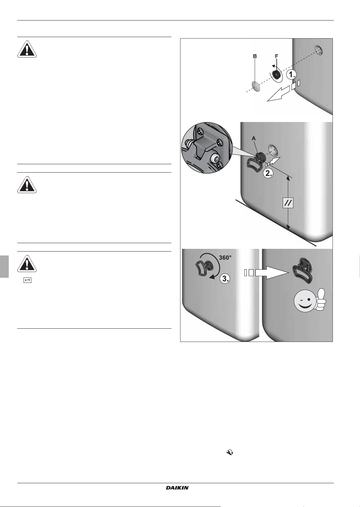
● Remove packing and dispose of it in an environment-friendly
manner.
● Remove the cover plates on the storage tank (figure 3-4,
item B) and unscrew the threaded pieces (figure 3-4, item F)
from the apertures on which the handles are to be mounted
(figure 2-2 to figure 2-5, item 24).
● Screw handles (figure 3-4, item A) into the threaded holes
that are now free.
A Handle
B Cover screen
Fig. 3-4 Attach handles
F Threaded piece
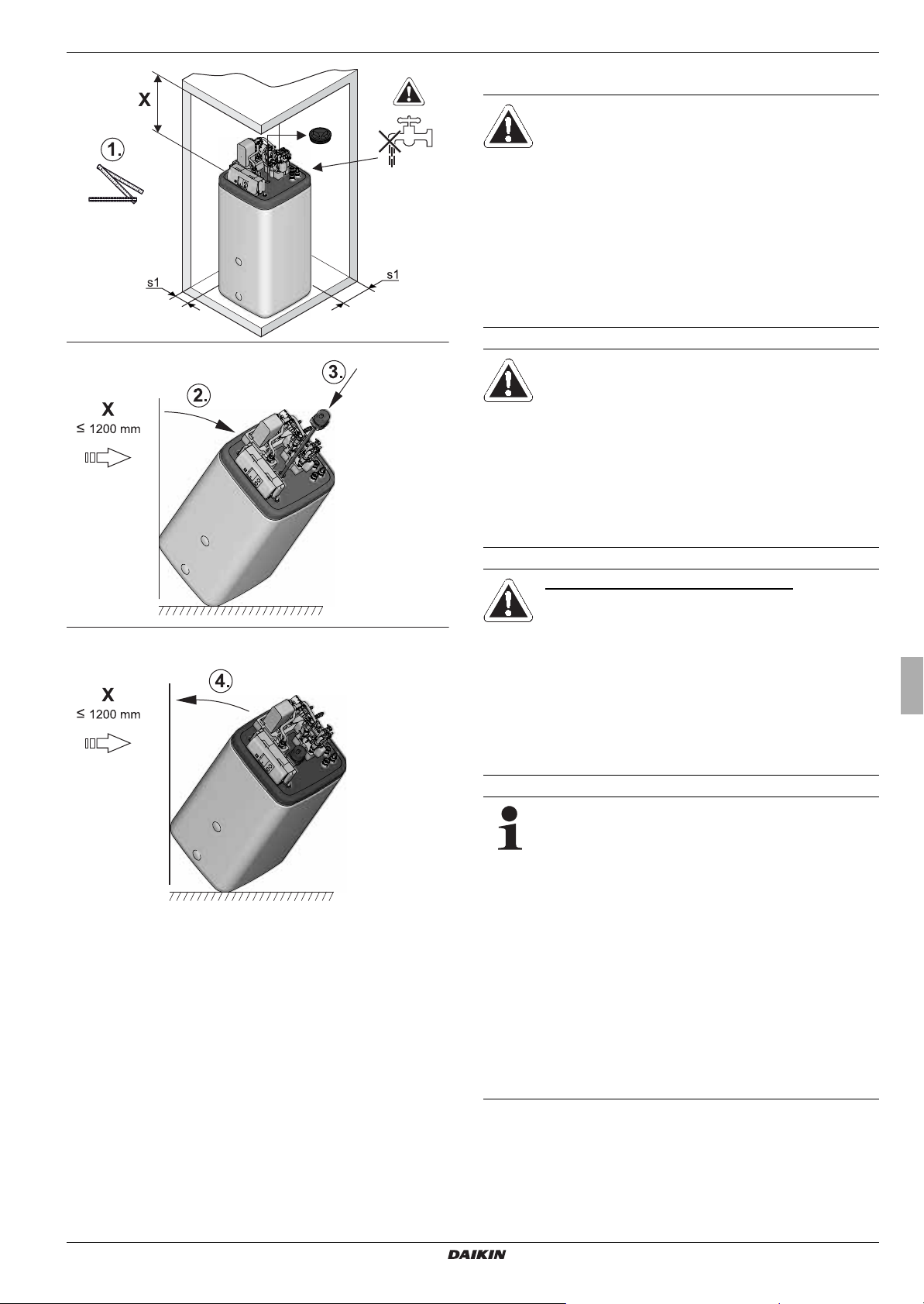
● Install the Daikin Altherma EHS(X/H) at the installation site.
– Recommended clearances (figure 3-5):
From the wall (s1): ≥ 200 mm.
From the ceiling (X): ≥ 1200 mm.
– Carefully transport the Daikin Altherma EHS(X/H), use the
handles.
– When setting up the unit in a cabinet, behind panels or in
other restricted conditions, sufficient ventilation (e.g.,
using ventilation gratings) must be ensured.
● If necessary, install the optional backup heater (EKBUxx) into
the Daikin Altherma EHS(X/H) (
figure 3-5).
Observe the assembly and operating manual supplied with
the accessory ( for tightening torque see chapter 9.3).
Installation and maintenance instructions
14
Daikin Altherma EHS(X/H)
Daikin Altherma integrated solar unit
008.1420744 – 08/2014
3 x Set-up and installation
3.3 Water connection
CAUTION:
If the Daikin Altherma EHS(X/H) is connected to a
heating system with steel pipes, radiators or non-diffusion-proof floor heating pipes, slurry and swarf could
enter the hot water storage tank and cause
blockages, local overheating or corrosion.
● Flush the feed pipes before filling the heat
exchanger.
● Rinse out the heat distribution network (in the
existing heating system).
● Install the dirt filter or sludge separator into the
heating return flow (see chapter
CAUTION:
If the Daikin Altherma EHS(X/H) is connected to a cold
water line, where steel pipes are used, chips can
enter the special steel corrugated pipe heat exchanger
and remain there. This can lead to contact corrosion
damage and subsequently to leakage.
● Flush the feed pipes before filling the heat
exchanger.
● Install contamination filter in the cold water feed
(see chapter
1.5.5).
1.5.5).
Fig. 3-5 Installation (shown using a Daikin Altherma EHS(X/H)...P50A
with integration of the optional back-up heater)
ONLY DAIKIN ALTHERMA EHS(X/H)B
CAUTION:
If the heat exchanger for charging the pressurised
solar system (figure 3-1/figure 3-2, item 8+9) has an
external heating unit (e.g. wood-burning boiler) con-
nected to it, an excessive flow temperature at these
connections can damage or destroy the Daikin Altherma EHS(X/H)B.
● The feed flow temperature of the external heater
should be limited to max. 95
°C.
In accordance with EN 12828 you must install a safety
valve at or in the immediate vicinity of the heat
exchanger, with which you can limit the maximum per
missible operating pressure in the heating system..
There should be no hydraulic blocking elements
between the heat generator and the safety valve.
Any steam or heating water which may escape must be
diverted by a suitable blow-off line with constant gradient in a frost-protected, safe and observable manner.
A diaphragm expansion vessel of adequate dimensions
and pre-set for the heating system must be connected
to the Daikin Altherma EHS(X/H). There should be no
hydraulic blocking elements between the heat genera
tor and the diaphragm expansion vessel.
Daikin recommends integrating a mechanical manometer for the filling of the heating system.
-
-
Daikin Altherma EHS(X/H)
Daikin Altherma integrated solar unit
008.1420744 – 08/2014
● For drinking water lines, comply with the EN 806 and
DIN 1988 stipulations.
● Install the Daikin Altherma EHS(X/H) near to the removal
point to dispense with the need for a circulation line. If a circulation line is absolutely essential, it must be installed in
accordance with the schematics in
chapter 8 "Hydraulic
Installation and maintenance instructions
15
3 x Set-up and installation
system connection".
3.3.1 Connecting hydraulic lines
Requirement: Optional accessories (e.g. Solar, backup heater)
mounted on the Daikin Altherma EHS(X/H) according to the
specifications of the instructions included.
● Check cold water pressure (maximum 6 bar).
– At higher pressure in the drinking water line, a pressure
reducer must be installed.
● Establish hydraulic connections at the Daikin Altherma
EHS(X/H).
– Position of the heating connections figure 3-1 / figure 3-2,
Dimensions to be taken from tab. 2 -1.
– Pay attention to the stipulated tightening torque (see
chapter 9.3 "Tightening torque").
– Design the lines as such that the sound attenuation cowl
can be applied without any problem following assembly.
– Connect the water for filling or refilling the heating system
as specified by EN 1717 to avoid contamination of drinking water by backwash.
● Connect the blow-off line to the safety over-pressure valve
and diaphragm expansion vessel in accordance with
12828.
EN
● Carefully insulate pipe lines against heat loss and so as to
avoid the formation of condensation (insulation thickness at
least 20
– Water shortage protection: The pressure and temperature
monitoring of the control unit safely switches off the Daikin
Altherma EHS(X/H) in the event of a water shortage. No addi
tional water shortage protection is needed in the construction.
– Avoid damages caused by deposits and corrosion:
Observe the relevant regulations of technology to prevent
creation of corrosion products and deposits.
Minimum requirements regarding the quality of filling and supplementary water:
– Water hardness (calcium and magnesium, calculated as
– Conductivity: ≤ 2700 μS/cm
– Chloride: ≤ 250 mg/l
– Sulphate: ≤ 250 mg/l
– pH value (heating water): 6,5 - 8,5
In the case of filling and top-up water with a high overall hardness
or other properties that deviate from the minimum requirements,
measures for the desalination, softening, hardness stabilisation
or other suitable conditioning measures are required to maintain
the required water quality.
mm).
calcium carbonate): ≤
3 mmol/l
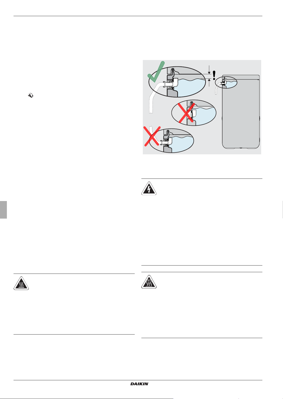
● Connect the drain hose to the connection piece for the safety
overflow (figure 2-2 to figure 2-5, item 23).
– Use transparent drain hose (draining water must be visi-
ble).
– Connect the drain hose to an adequately dimensioned
waste water installation.
– Drain should not be lockable.
Fig. 3-6 Installation of drain hose at safety overflow
3.4 Electrical connection
-
WARNING!
Touching live parts can result in an electric shock
and lead to potentially fatal injuries and burns.
● Before beginning work on live parts, disconnect
all of the systems circuits from the power supply
(switch off main switch, disconnect fuse) and
secure against unintentional restart.
● The electrical connection and working on the
electrical components should only be performed
by electrical engineers in compliance with valid
standards and guidelines as well as the specifica
tions of the energy supply company.
● The equipment covers and maintenance
opening covers must be re-fitted immediately
after completion of the work.
-
WARNING!
There is a danger of scalding at hot water temperatures over 60 °C. This is possible, when solar energy is
used, with a connected external heating device, when
the Legionella protection is activated or when the domestic hot water target temperature is set higher than
60 °C. Only drain the storage tank container or heating
system
● Install scald protection (hot water mixer (e.g.
VTA32).
Installation and maintenance instructions
16
CAUTION:
Increased temperatures may arise in the control
housing of the Daikin Altherma EHS(X/H) during op
eration. This can result in currently-carrying wires
from reaching higher temperatures during operation
due to self-heating. For this reason, these lines must
have a temperature for continuous use of 90
°C.
● For the following connections, use only cables with
a long-term use temperature ≥ 90 °C:
– Exterior heat pump unit
– Optional: Electrical backup heater (EKBUxx)
Daikin Altherma EHS(X/H)
Daikin Altherma integrated solar unit
008.1420744 – 08/2014
-
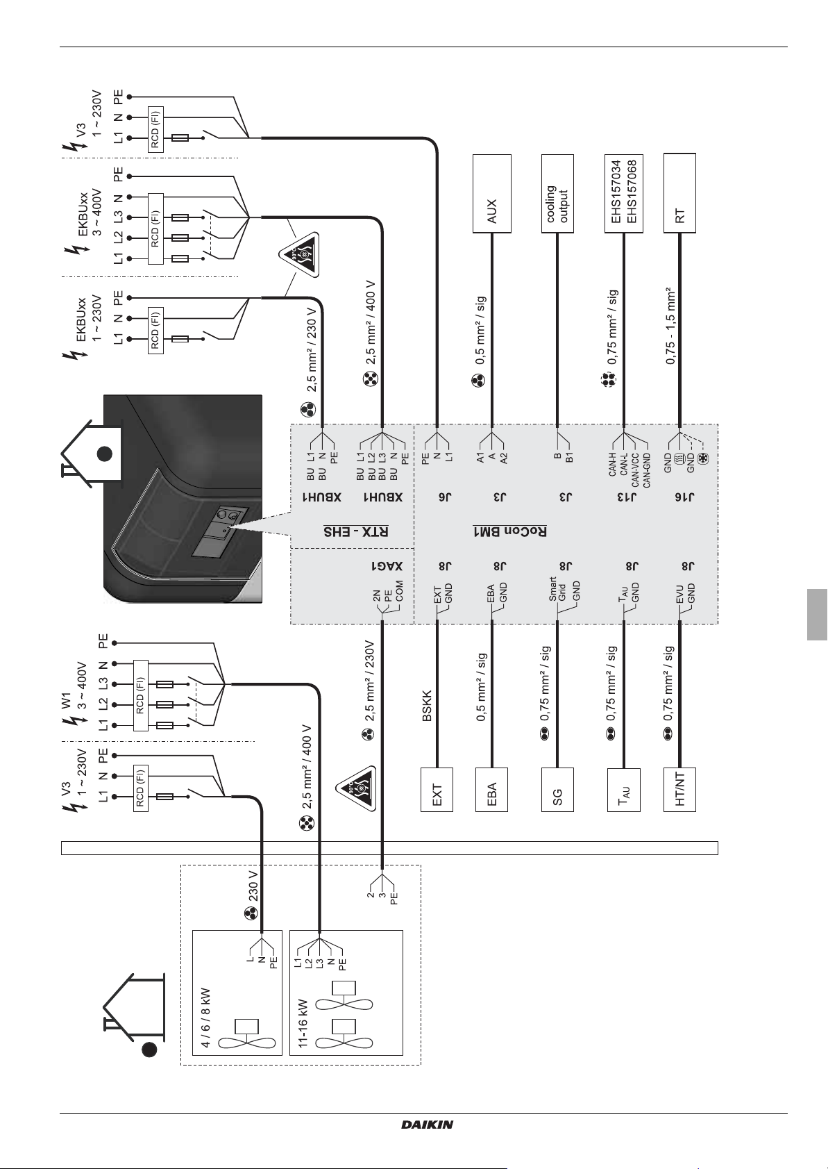
3.4.1 Overall connection plan Daikin Altherma EHS(X/H)
3 x Set-up and installation
Fig. 3-7 Overall connection diagram - for electrical connection during device installation
Daikin Altherma EHS(X/H)
Daikin Altherma integrated solar unit
008.1420744 – 08/2014
Installation and maintenance instructions
17
3 x Set-up and installation
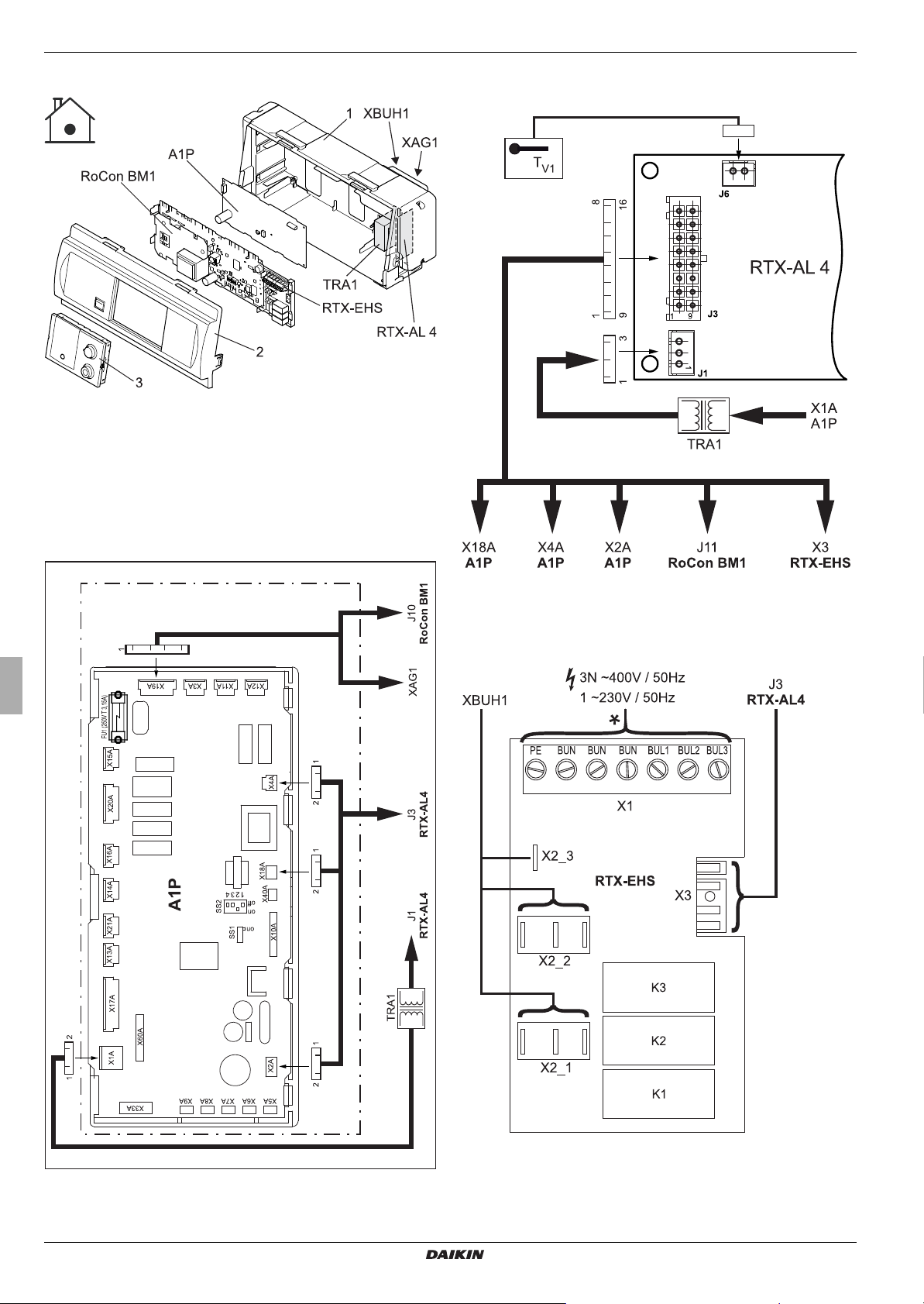
3.4.2 Position of the circuit boards
1 Control housing
2 Control panel
3 Control unit for the control
Fig. 3-8 Overview circuit boards (internal housing)
For further legend descriptions see tab. 3 -3
3.4.3 Connection assignment, circuit board A1P
The A1P circuit board comes pre-connected to the unit. No assembly or connection work is necessary on the A1P circuit board!
3.4.4 Terminal assignment for the RTX-AL4 circuit board
Fig. 3-10 Circuit board RTX-AL4 (interface)
3.4.5 Terminal assignment for the RTX-EHS circuit board
Fig. 3-9 Circuit board A1P (basic control of the heat pump)
Installation and maintenance instructions
18
Fig. 3-11 Circuit board RTX-EHS (backup heater)
Daikin Altherma integrated solar unit
Daikin Altherma EHS(X/H)
008.1420744 – 08/2014
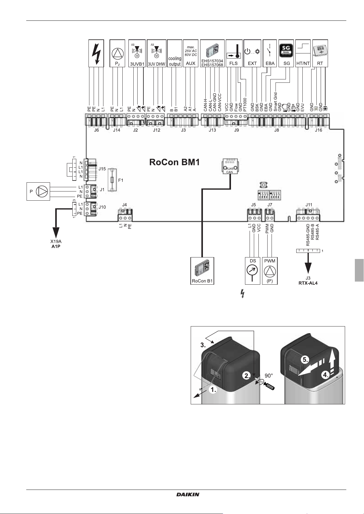
3.4.6 Connection assignment, circuit board RoCon BM1
3 x Set-up and installation
Fig. 3-12 Circuit board RoCon BM1 (Basic control module)
3.4.7 Mains connection Daikin Altherma EHS(X/H)
A flexible cable for the mains connection is already connected internal to the device.
● Check the supply voltage (~230 V, 50 Hz).
● Disconnect the junction box of the domestic installation.
● Connect the cable for the mains connection on the Daikin
Altherma EHS(X/H) to the junction box of the domestic instal
lation via an all-pole disconnecting main switch to be installed
by the customer (separate isolator according to EN 60335-1).
Ensure that the polarity is correct.
The exterior unit and optional accessories must be connected
separately to the regulator on the Daikin Altherma EHS(X/H). To
do so, the cover panel of the Daikin Altherma EHS(X/H) must be
removed (see section
housing opened (see section 3.4.9).
3.4.8) and, if necessary, the control
Mains supply 230 V, 50 Hz
(Connection plan in this instruction manual)
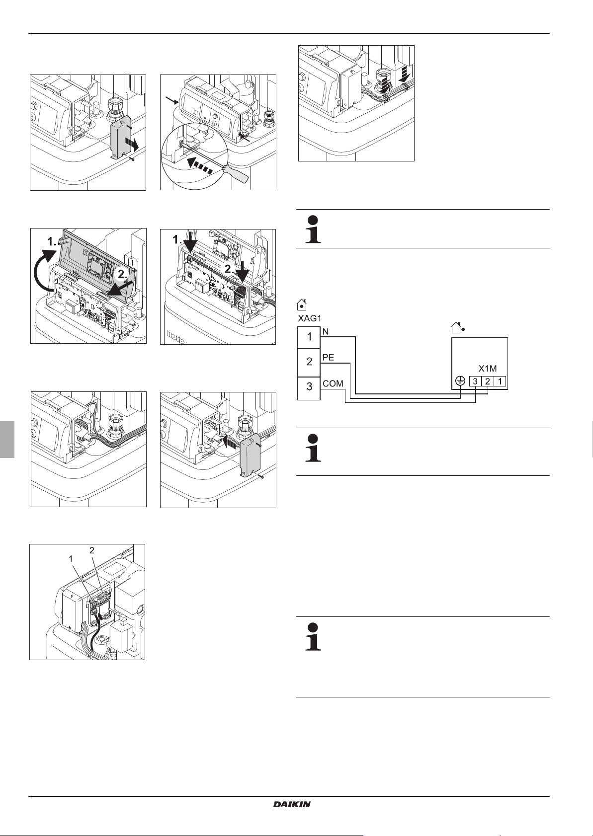
3.4.8 Removing the protective cover
-
Fig. 3-13 Unscrew/loosen the screws, lift up the cover panel at the back
and pull forwards.
Daikin Altherma EHS(X/H)
Daikin Altherma integrated solar unit
008.1420744 – 08/2014
Installation and maintenance instructions
19
3 x Set-up and installation
3.4.9 Opening the control housing and establishing electrical connections
Fig. 3-21 Fasten cabling on the storage container.
Fig. 3-14 Dismount right housing
cover.
Fig. 3-16 Open front panel and
place in assembly posi
tion.
Fig. 3-15 Unlock front panel.
Fig. 3-17 Route cabling into the
-
regulator and make the
electrical connections.
3.4.10 Connection of ERLQ exterior heat pump unit
This component has a separate manual attached,
including among other things instructions for installation
and operation.
● Dismount the protective cover (see section 3.4.8).
● Connect the exterior heat pump unit to the terminal strip
XAG1 (see figure 3-20, figure 3-22).
Fig. 3-22 Connection of exterior heat pump unit
When switching off the heat pump exterior unit using a
switching system prescribed by the energy supply company (EVU), the internal Daikin Altherma EHS(X/H)
device is not disconnected (see section
3.4.21).
Fig. 3-18 Lay cables in the right
housing cover.
Fig. 3-20 Make the electrical connections to the rear of the housing (see
section
3.4.1).
Fig. 3-19 Install the right housing
cover.
1 XAG1 Terminal block for exte-
rior unit
2 XBUH1 Terminal block for
backup heater
3.4.11 Connection of external temperature sensor RoCon OT1
The exterior heat pump unit of the Daikin Altherma EHS(X/H) has
a built-in exterior temperature sensor which is used to regulate
the inflow temperature depending on the weather, with frost pro
tection function.
Instead of the exterior temperature sensor built into the exterior
heat pump unit, the optional exterior temperature sensor RoCon
OT1 can also be used to regulate the inflow temperature de
pending on the weather, with frost protection function.
If the Daikin Altherma EHS(X/H) is used in a CAN bus
system as a master ("terminal function" for the remote
control of other data bus devices), the exterior temper
ature sensor RoCon OT1 must be connected directly
to the regulator RoCon HP on the master and not to
the remote controlled device (mixer circuit module
EHS157068 or a different heat generator).
-
-
-
Installation and maintenance instructions
20
Daikin Altherma EHS(X/H)
Daikin Altherma integrated solar unit
008.1420744 – 08/2014
 Loading...