

Daikin EHS04P30A, EHSB04P30A, EHS08P30A, EHSB08P30A, EHS08P50A Operation manuals
...
Operating instructions
Indoor unit for air-water-heat pumps
Daikin Altherma integrated solar unit
Daikin Altherma
EHS(X/H)04P30A
EHS(X/H)B04P30A
EHS(X/H)08P30A
EHS(X/H)B08P30A
EHS(X/H)08P50A
EHS(X/H)B08P50A
EHS(X/H)16P50A
EHS(X/H)B16P50A
Operating instructions
Daikin Altherma integrated solar unit
English

List of contents
1 Safety . . . . . . . . . . . . . . . . . . . . . . . . . . . . . . 3
1.1 Observing instructions . . . . . . . . . . . . . . . . . . . . 3
1.2 Warning signs and explanation of symbols . . . . 3
1.2.1 Meaning of the warnings. . . . . . . . . . . . . . . . . . . . .3
1.2.2 Validity. . . . . . . . . . . . . . . . . . . . . . . . . . . . . . . . . . .3
1.2.3 Handling instructions. . . . . . . . . . . . . . . . . . . . . . . .3
1.3 Avoid danger . . . . . . . . . . . . . . . . . . . . . . . . . . . 3
1.4 Intended use . . . . . . . . . . . . . . . . . . . . . . . . . . . 4
1.5 Instructions for operating safety . . . . . . . . . . . . . 4
2 Product description. . . . . . . . . . . . . . . . . . . 5
2.1 Brief description . . . . . . . . . . . . . . . . . . . . . . . . . 5
2.1.1 Mode of operation . . . . . . . . . . . . . . . . . . . . . . . . . .5
2.1.2 Solar support. . . . . . . . . . . . . . . . . . . . . . . . . . . . . .6
2.1.3 Safety management . . . . . . . . . . . . . . . . . . . . . . . .6
2.1.4 Electronic control. . . . . . . . . . . . . . . . . . . . . . . . . . .6
2.2 Design and components . . . . . . . . . . . . . . . . . . 6
2.2.1 System overview . . . . . . . . . . . . . . . . . . . . . . . . . . .6
2.2.2 Device external and internal design Daikin Altherma
EHS(X/H)...P30A. . . . . . . . . . . . . . . . . . . . . . . . . . .7
2.2.3 Device external and internal design Daikin Altherma
EHS(X/H)B...P30A . . . . . . . . . . . . . . . . . . . . . . . . .8
2.2.4 Device external and internal design Daikin Altherma
EHS(X/H)...P50A. . . . . . . . . . . . . . . . . . . . . . . . . . .9
2.2.5 Device external and internal design Daikin Altherma
EHS(X/H)B...P50A . . . . . . . . . . . . . . . . . . . . . . . .10
3 Operation . . . . . . . . . . . . . . . . . . . . . . . . . . 12
3.1 General . . . . . . . . . . . . . . . . . . . . . . . . . . . . . . 12
3.2.1 Display . . . . . . . . . . . . . . . . . . . . . . . . . . . . . . . . .12
3.2.2 Operating elements. . . . . . . . . . . . . . . . . . . . . . . .13
3.3 Operating concept . . . . . . . . . . . . . . . . . . . . . . 14
3.4 Basic functions and operating modes . . . . . . . 15
3.4.1 System information (Info) . . . . . . . . . . . . . . . . . . .15
3.4.2 Setting the operating mode. . . . . . . . . . . . . . . . . .17
3.4.3 Temperature setting Daytime room temperature .18
3.4.4 Temperature setting Economy mode . . . . . . . . . .19
3.4.5 Temperature setting hot water generation . . . . . .19
3.4.6 Unscheduled hot water generation . . . . . . . . . . . .19
3.4.7 Switching time program. . . . . . . . . . . . . . . . . . . . .19
3.4.8 System settings. . . . . . . . . . . . . . . . . . . . . . . . . . .21
3.4.9 Terminal function. . . . . . . . . . . . . . . . . . . . . . . . . .22
3.4.10 Quite Mode . . . . . . . . . . . . . . . . . . . . . . . . . . . . . .22
3.5 Special functions . . . . . . . . . . . . . . . . . . . . . . . 23
3.5.1 Manual Operation . . . . . . . . . . . . . . . . . . . . . . . . .23
3.6 Special system settings . . . . . . . . . . . . . . . . . . 24
3.6.1 Access Rights (Technician password) . . . . . . . . .24
3.6.2 Heat curve. . . . . . . . . . . . . . . . . . . . . . . . . . . . . . .24
3.6.3 Cooling characteristic curve . . . . . . . . . . . . . . . . .25
3.6.4 Weather-controlled flow temperature regulation . .26
3.6.5 Frost protection function . . . . . . . . . . . . . . . . . . . .26
3.6.6 Legionella protection. . . . . . . . . . . . . . . . . . . . . . .27
3.6.7 Reset to factory settings (Reset). . . . . . . . . . . . . .27
3.6.8 Settings for optional circulation pump . . . . . . . . . .27
3.6.9 Remote control via Internet . . . . . . . . . . . . . . . . . .28
4 Commissioning . . . . . . . . . . . . . . . . . . . . . 29
4.1 Initial commissioning . . . . . . . . . . . . . . . . . . . . 29
4.2 Re-commissioning . . . . . . . . . . . . . . . . . . . . . . 29
4.2.1 Requirements . . . . . . . . . . . . . . . . . . . . . . . . . . . .29
4.2.2 Start-up . . . . . . . . . . . . . . . . . . . . . . . . . . . . . . . . .29
5 Decommissioning . . . . . . . . . . . . . . . . . . . .30
5.1 Temporary shutdown . . . . . . . . . . . . . . . . . . . 30
5.1.1 Draining the storage tank . . . . . . . . . . . . . . . . . . 30
5.1.2 Draining the heating circuit and hot water circuit. 31
5.2 Final shutdown . . . . . . . . . . . . . . . . . . . . . . . . 32
6 Parameter settings . . . . . . . . . . . . . . . . . . .33
6.1 Explanation of the parameter tables . . . . . . . . 33
6.2 Rotary switch setting: Configuration . . . . . . . . 33
6.2.1 Level "Setup". . . . . . . . . . . . . . . . . . . . . . . . . . . . 33
6.2.2 Level "System Configuration" . . . . . . . . . . . . . . . 33
6.2.3 Level "HC Configuration". . . . . . . . . . . . . . . . . . . 34
6.2.4 Level "DHW Configuration" . . . . . . . . . . . . . . . . . 35
6.3 Rotary switch setting: DHW Install . . . . . . . . . 35
6.4 Rotary switch setting: Operating Mode . . . . . 35
6.5 Rotary switch setting: Set Temp Day . . . . . . . 36
6.6 Rotary switch setting: Set Temp Night . . . . . . 36
6.7 Rotary switch setting: DHW Set Temp . . . . . . 36
6.8 Rotary switch setting: Time Program . . . . . . . 37
6.9 Rotary switch setting: Remote Param . . . . . . 37
6.10 Rotary switch setting: Info . . . . . . . . . . . . . . . 38
6.11 Exit button: Sonderfunktion . . . . . . . . . . . . . . . 38
6.12 Parameter levels for the EHS157068 mixer
module . . . . . . . . . . . . . . . . . . . . . . . . . . . . . . 39
6.12.1 Rotary switch setting: Configuration,
level "Setup" . . . . . . . . . . . . . . . . . . . . . . . . . . . . 39
6.12.2 Rotary switch setting: Configuration,
level "Mixer Config" . . . . . . . . . . . . . . . . . . . . . . . 39
7 Service and maintenance . . . . . . . . . . . . . .41
7.1 General . . . . . . . . . . . . . . . . . . . . . . . . . . . . . . 41
7.2 Removing the protective cover . . . . . . . . . . . . 41
7.3 Activities to be performed annually . . . . . . . . . 41
7.4 Filling and topping up the storage tank . . . . . . 42
7.5 Filling and topping up the heating system. . . . 43
8 Errors, malfunctions and messages . . . . .45
8.1 Deleting errors, correcting malfunctions, deleting
messages . . . . . . . . . . . . . . . . . . . . . . . . . . . . 45
8.1.1 Current fault display . . . . . . . . . . . . . . . . . . . . . . 45
8.1.2 Read Protocol . . . . . . . . . . . . . . . . . . . . . . . . . . . 45
8.1.3 Troubleshooting. . . . . . . . . . . . . . . . . . . . . . . . . . 45
8.2 Malfunctions . . . . . . . . . . . . . . . . . . . . . . . . . . 46
8.3 Fault codes . . . . . . . . . . . . . . . . . . . . . . . . . . . 49
8.4 Emergency operation . . . . . . . . . . . . . . . . . . . 49
9 Glossary . . . . . . . . . . . . . . . . . . . . . . . . . . . .50
10 Notes. . . . . . . . . . . . . . . . . . . . . . . . . . . . . . .52
10.1 User-specific settings . . . . . . . . . . . . . . . . . . . 52
10.1.1 Switching timer program . . . . . . . . . . . . . . . . . . . 52
10.2 Parameter . . . . . . . . . . . . . . . . . . . . . . . . . . . . 53
10.2.1 Data bus addresses . . . . . . . . . . . . . . . . . . . . . . 53
10.3 Other items . . . . . . . . . . . . . . . . . . . . . . . . . . . 54
11 List of keywords . . . . . . . . . . . . . . . . . . . . .55
Operating instructions
2
Daikin Altherma EHS(X/H)
Daikin Altherma integrated solar unit
008.1420944 – 05/2014
1Safety
1 x Safety
1.1 Observing instructions
These instructions are a >> Translation of the original
version << in your language.
All the activities required for operation and setting the parameters
are described in this instruction manual. All parameters needed
for trouble-free operation have been configured at the factory.
● Please read through this manual carefully before operating
the heating system or before adjusting the settings for it.
● Make a note of the preset values before you make any
changes to the unit configuration.
● Comply strictly with warning instructions.
● Installation and all modifications / settings of the device not
described in this manual may be performed only by qualified
and authorised specialist heating technicians.
Relevant documents
– Daikin Altherma EHS(X/H):
– Installation and maintenance instructions
– Operating instructions for the RoCon HP control unit
– External unit for Daikin Altherma EHS(X/H); the associated
installation and operating instructions.
– When connecting to a Daikin solar system; the associated
installation and operating instructions.
– If a Daikin FWXV(15/20)AVEB is connected; the associated
installation and operating instructions.
– In the case of connection to a control component offered as
an accessory (room controller, mixer module etc.); the associated installation and operating instructions.
The guides are included in the scope of supply for the individual
units.
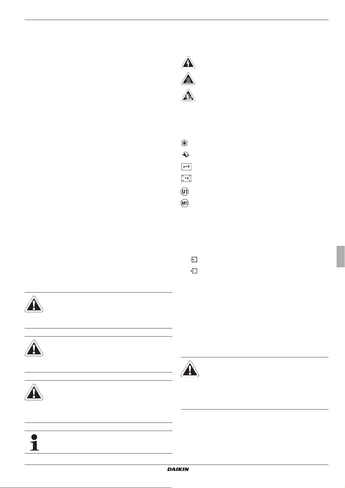
1.2 Warning signs and explanation of symbols
Special warning signs
Some types of danger are represented by special symbols:
Electric power
Risk of burning or scalding
Risk of environmental damage
1.2.2 Validity
Some information in this manual has limited validity. The validity
is highlighted by a symbol.
Only valid for Daikin Altherma EHS(X/H) with cooling
function
Comply with the specified tightening torque (see installation and maintenance manual)
Only applicable for the unpressurised solar system (Drain
Back)
Only applicable for the pressurised solar system.
Only valid/available if a room regulator is connected
Only valid/available if a mixer module is connected
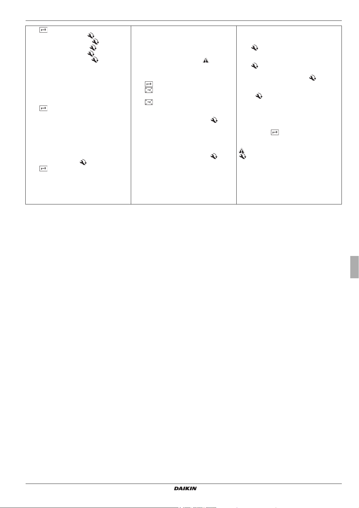
1.2.3 Handling instructions
● Instructions on actions are shown as a list. Actions of which
the sequential order must be maintained are numbered.
Results of actions are identified with an arrow.
Entry into a setting procedure
1.2.1 Meaning of the warnings
Warnings in this manual are classified according into their severity and probability of occurrence.
DANGER!
Draws attention to imminent danger.
Disregarding this warning can lead to serious injury or
death.
WARNING!
Indicates a potentially dangerous situation.
Disregarding this warning can result in serious injury
or death.
CAUTION!
Indicates a situation which may cause possible
damage.
Disregarding this warning can lead to damage to
property and the environment.
This symbol identifies user tips and particularly useful
information, but not warnings or hazards.
Exit from a setting procedure
1.3 Avoid danger
The Daikin Altherma EHS(X/H) is state-of-the-art and is built to
meet all recognised technical requirements. However, improper
use may result in serious physical injuries or death, as well as
property damage.
To avoid danger, only operate the Daikin Altherma EHS(X/H):
– as stipulated and in perfect condition,
– with an awareness of the safety and hazards involved.
This assumes knowledge and use of the contents of this manual.
WARNING!
This unit is not intended for use by persons (including
children) with impaired physical, sensory or mental
faculties or persons with insufficient experience and/or
expertise unless supervised by a person responsible
for ensuring their safety or are given instruction by this
person on how to use the unit.
Daikin Altherma EHS(X/H)
Daikin Altherma integrated solar unit
008.1420944 – 05/2014
Operating instructions
3
1 x Safety
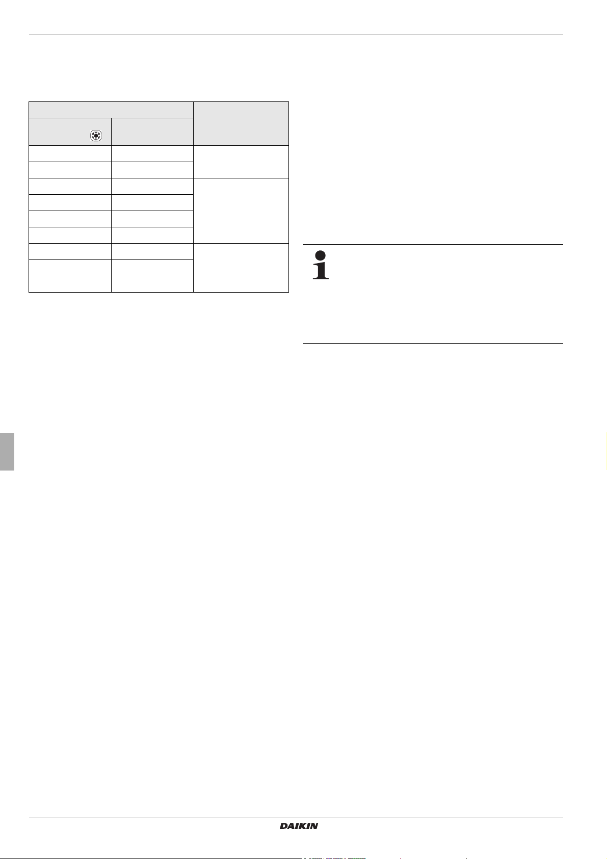
1.4 Intended use
The Daikin Altherma EHS(X/H) may only be used for preparation
of hot water, as a room heating system, and depending on its
design, as a room cooling system.
Internal unit External unit
Heating and
cooling (X)
EHSX04P30A EHSH04P30A
EHSXB04P30A EHSHB04P30A
EHSX08P30A EHSH08P30A
EHSXB08P30A EHSHB08P30A
EHSX08P50A EHSH08P50A
EHSXB08P50A EHSHB08P50A
EHSX16P50A EHSH16P50A ERLQ011CA(V3/W1)
EHSXB16P50A
B - Additional heat exchanger for the bivalent connection
Tab. 1-1 Permissible combinations of Daikin exterior heat pump units
and Daikin Altherma EHS(X/H) internal units
Any other use outside the intended use is considered as improper. The operator alone shall bear responsibility for any resulting damage.
Use as intended also involves compliance with maintenance and
inspection conditions. Spare parts must at least satisfy the tech
nical requirements defined by the manufacturer. This is the case,
for example, with original spare parts.
Heating only (H)
EHSHB16P50A
ERLQ004CAV3
ERLQ006CAV3
ERLQ008CAV3
ERLQ014CA(V3/W1)
ERLQ016CA(V3/W1)
1.5 Instructions for operating safety
● Work on the Daikin Altherma EHS(X/H) (such as setup,
servicing, connection and initial start-up) is only to be carried
out by persons who are authorised and who have success
fully completed qualifying technical or vocational training and
who have taken part in advanced training sessions recognised by the appropriate responsible authorities. This, in
particular, includes heating specialists and climate control
technicians who have experience, as a result of their
technical training and their knowledge of the subject, of
proper and appropriate installation and maintenance of
heating, climate control and cooling installations and heat
pumps.
● Electrical installation may be carried out only by electrical
engineers and in compliance with the valid electro-technical
guidelines as well as the regulations of the relevant energy
supply company (EVU).
For work on stationary refrigeration systems (heat
pumps) and air conditioning systems, proof of expertise
is required in the European Community according to
the F-Gases Directive (EC) No. 303/2008.
– up to 3 kg coolant fill quantity: Expert certificate
category II
–3 kg coolant fill quantity or over: Expert certifi-
cate category I
Observe the current technological regulations to prevent corrosion products and deposits.
-
Minimum requirements regarding the quality of filling and supplementary water:
– Water hardness (calcium and magnesium, calculated as
calcium carbonate): ≤ 3 mmol/l
– Conductivity: ≤ 2700 μS/cm
– Chloride: ≤ 250 mg/l
– Sulphate: ≤ 250 mg/l
– pH value (heating water): 6,5 - 8,5
-
Using filling water and top-up water which does not meet the
stated quality requirements can cause a considerably reduced
service life of the equipment. The responsibility for this lies solely
with the operator.
Operating instructions
4
Daikin Altherma EHS(X/H)
Daikin Altherma integrated solar unit
008.1420944 – 05/2014

2 Product description
2 x Product description
2.1 Brief description
The air-water heat pump system uses the physical effect of condensation and latent heat and makes it possible as required to
heat or cool buildings. The Daikin Altherma EHS(X/H) (Altherma
integrated solar unit) is the primary component of the highly-effi
cient heating- and cooling system for domestic applications.
Located in the external heat pump unit (ERLQ) are the coolant
compressor and a finned heat exchanger, which, in heating
mode, acts as a vaporiser and extract heat from the ambient air.
In cooling mode this acts as a condensator and returns heat to
the environment (refrigerator principle).
The heat pump external unit is connected to the heat pump internal unit in the building by means of a closed coolant circuit.
Heat or cold is transported between the heat pump external unit
and the heat pump internal unit by means of the circulating refrigerant, which alternately takes on the liquid and gaseous phases.
The internal heat pump unit contains the control devices, the heat
exchanger and integrated storage tank. In the heat exchanger,
the heat is transferred to the water flowing in the heating circuit or
the water in the storage tank (heating/hot water supply), or heat
is extracted from the water (cooling).
The storage tank on the Daikin Altherma EHS(X/H) is built in such
a way to enable the heat pump system to be combined with a
Daikin solar system without needing an additional hot water tank.
With optional solar heating, the entire hot water storage tank can
be heated, depending on the heat offered by the sun. The stored
heat is used both for hot water heating and for heating support.
The high total storage capacity also temporarily allows time
without sunshine to be bridged. The excellent heat insulation
properties of the integrated storage tank also ensure that heat
losses are kept to a minimum. This allows efficient and economic
water heating and also solar support.
If the heating capacity of the Altherma EHS(X/H) is not adequate,
the optional backup heater (EKBUxx) can provide additional
heating capacity for heating the heating circuit.
In order to make more cost effective use of the Daikin Altherma
EHS(X/H), it can be operated on a low tariff network connection
(HT/NT) or with an intelligent controller (SMART GRID). Here the
energy supply company (EVU) is afforded the opportunity to
control their network utilisation by changing the heat pump oper
ating mode. Information on the prerequisites and connection possibilities are described in the enclosed installation manual.
2.1.1 Mode of operation
In room heating mode the refrigerant which was compressed in
the refrigerant compressor in the heat pump external unit con
denses in the plate heat exchanger in the heat pump internal unit.
The heat released during the liquefaction of the coolant is trans-
ferred to the heating water in the plate heat exchanger. The heat
circulating pump ensures the required flow of the heating water in
the internal hear generation circuit.
The lower the required temperature in the heating circuit, the more effectively the heat pump works.
It is, in particular, possible to achieve the lowest flow
temperatures possible with under-floor heating, as the
heat transfer surface is very large. Furthermore, the
building to be heated should ideally have extremely
good heat insulation, so that when there is a low heat
requirement, the heat carrier can run with a low flow
temperature.
The hot water zone of the storage tank integrated into the interior
heat pump unit is heated by the heat pump or other external heat
generators (solar system, backup heater. The cold water flowing
downstream of the hot water extraction cools the lower area of
the integrated storage tank to maximum effect.
The drinking water is heated indirectly in a corrosion resistant
stainless steel corrugated pipe heat exchanger by the unpres
surised water from the integrated storage tank. On its way to the
top, it continuously absorbs the heat from the storage tank water.
The flow direction, operating on the principle of counter-flow, and
the coil-shaped heat exchanger create a pronounced temperature layering in the hot water storage tank. As high temperatures
can be maintained for a very long time in the upper section of the
storage tank, a high hot water output is achieved even if water is
drawn off over a long period of time.
In the case of room cooling the 3-way switching valves
(3UV1 + 3UVB) mounted on the heat pump internal unit switches
off the flow to storage tank charging/heating support. The heat
circulation pump of the heat pump internal device now operates
exclusively within the heating circuit.
The cooling process now takes place by inverting the heat pump
process in the heat pump external unit. Thus the heat exchanger
of the heat pump internal unit acts as a vaporiser and extracts
heat from the heating water that flows through it. This cools the
heating circuit.
-
-
Daikin Altherma EHS(X/H)
Daikin Altherma integrated solar unit
008.1420944 – 05/2014
Operating instructions
5
2 x Product description
2.1.2 Solar support
The Daikin Altherma EHS(X/H) is prepared for integration into a
Daikin solar system.
The pressureless Daikin Solar-System (Drain Back), and in
the case of Daikin Altherma EHS(X/H)B type systems the Daikin
Solar-Pressure system can be used.
The high performance flat collectors are highly effective in converting solar radiation into heat, which is transferred via the solar
circuit into the integrated storage tank of the Daikin Altherma
EHS(X/H).
The heat that is fed in is transferred to the hot water circuit. If
there are sufficiently high temperatures in the hot water tank the
solar heat is also used for heating support. The RoCon HP
control unit controls this heat distribution fully automatically.
2.1.3 Safety management
The total security management of the Daikin heat pump system
is assumed by the electronic control integrated in the Daikin Altherma EHS(X/H). In the event of a water shortage, loss of refrigerant or undefined operating states, a safety switch-off is performed. A corresponding fault signal provides an engineer with all
the necessary information for troubleshooting.
2.1.4 Electronic control
2.2 Design and components
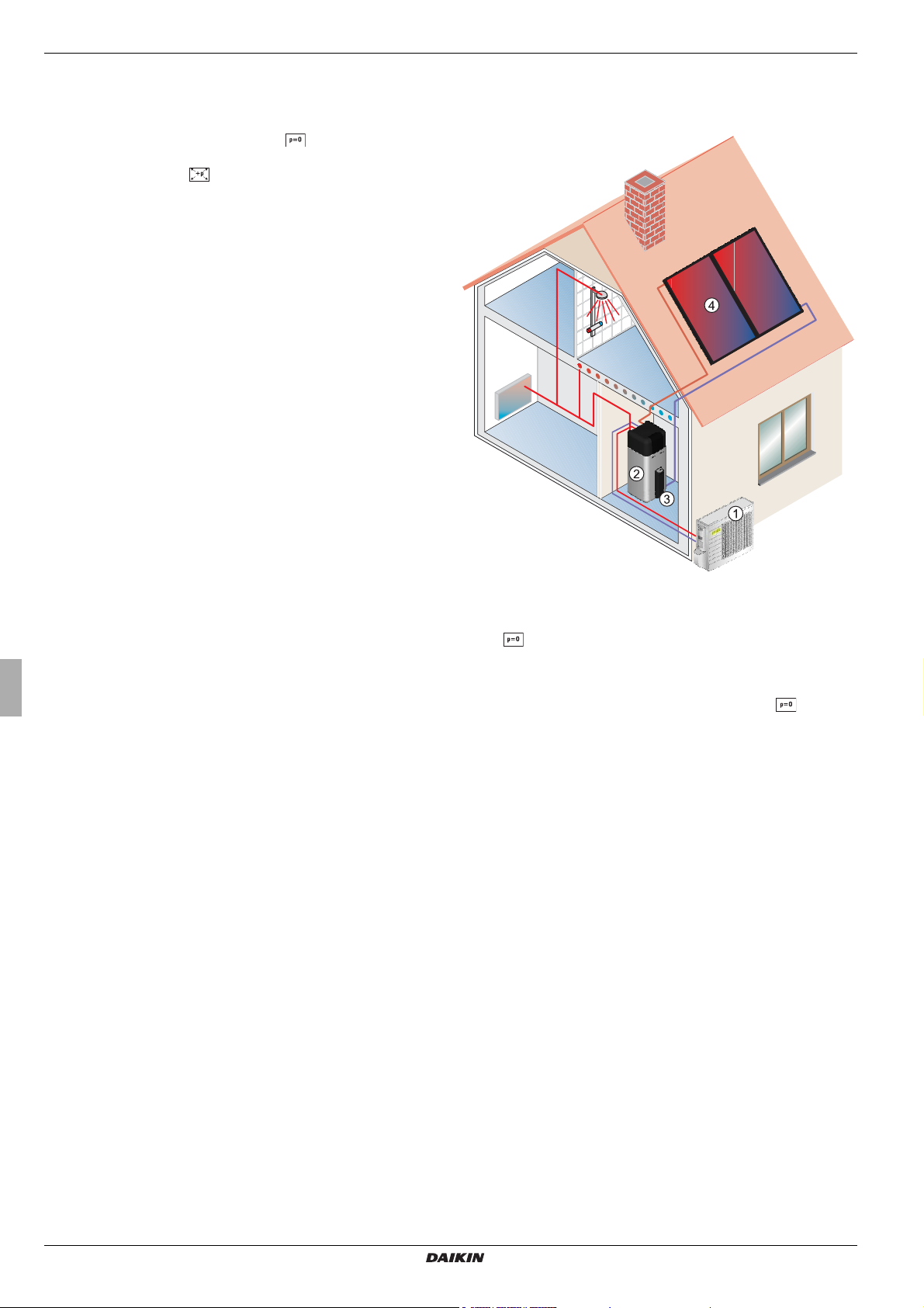
2.2.1 System overview
Depending on the heating unit, the RoCon HP electronic digital
controller automatically controls all the heating, cooling and hot
water functions for a direct heating circuit, a storage tank
charging circuit and, using optionally connected mixer modules,
additional heating circuits as well.
All function settings for the Daikin Altherma EHS(X/H) and the optional equipment (terminal function) connected via the data bus
are performed by the operating elements of the RoCon B1 integrated into the controls and are displayed in clear text on a coloured backlit ground.
The display and operation of a connected Daikin solar system are
performed by the associated controller for this component (e.g.,
Control and Pump Unit EKSRPS3B).
1 Heat pump external unit (ERLQ)
2 Daikin Altherma integrated solar unit (Altherma EHS(X/H))
Daikin Solar system (optional):
3 Solar control and pump unit
4 Solar panels
Fig. 2-1 Components of the heat pump system with the Daikin Alther-
ma EHS(X/H) internal unit and optional Daikin solar system
Operating instructions
6
Daikin Altherma EHS(X/H)
Daikin Altherma integrated solar unit
008.1420944 – 05/2014
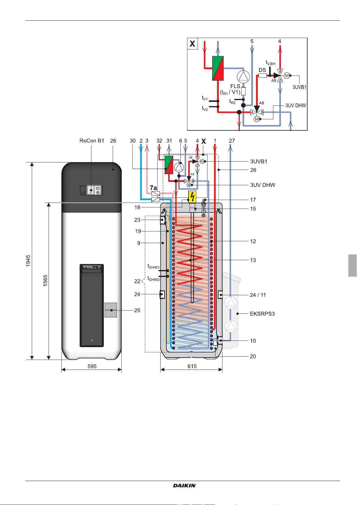
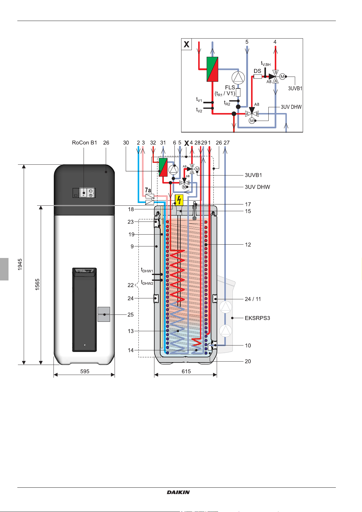
2.2.2 Device external and internal design Daikin Altherma EHS(X/H)...P30A
2 x Product description
Fig. 2-2 Design and components of the Daikin Altherma EHS(X/H)...P30A (external view and internal design)
For legend descriptions see tab. 2-1
Daikin Altherma EHS(X/H)
Daikin Altherma integrated solar unit
008.1420944 – 05/2014
Operating instructions
7
2 x Product description
2.2.3 Device external and internal design Daikin Altherma EHS(X/H)B...P30A
Fig. 2-3 Design and components of the Daikin Altherma EHS(X/H)B...P30A (external view and internal design)
For legend descriptions see tab. 2-1
Operating instructions
8
Daikin Altherma EHS(X/H)
Daikin Altherma integrated solar unit
008.1420944 – 05/2014
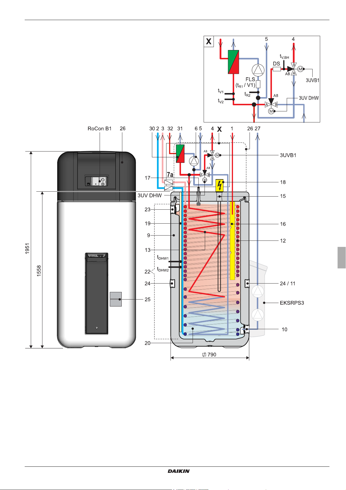
2.2.4 Device external and internal design Daikin Altherma EHS(X/H)...P50A
2 x Product description
Fig. 2-4 Design and components of the Daikin Altherma EHS(X/H)...P50A (external view and internal design)
Daikin Altherma EHS(X/H)
Daikin Altherma integrated solar unit
008.1420944 – 05/2014
For legend descriptions see tab. 2-1
Operating instructions
9

2 x Product description
2.2.5 Device external and internal design Daikin Altherma EHS(X/H)B...P50A
Fig. 2-5 Design and components of the Daikin Altherma EHS(X/H)B...P50A (external view and internal design)
For legend descriptions see tab. 2-1
Operating instructions
10
Daikin Altherma EHS(X/H)
Daikin Altherma integrated solar unit
008.1420944 – 05/2014
2 x Product description
1 Solar - flow or connection for addition-
al heat source (1" IG)
2 Cold water flow (1" AG)
3 Hot water flow (1" AG)
4 Heating flow (1" AG)*
5 Heating return (1" AG)*
6 Circulation pump
7a Recommended accessories:
non-return valves (2 pcs.)
9 Storage tank (double walled jacket made
of polypropylene with PUR hard foam heat
insulation)
10 Filling and drainage connection or
Solar - Return flow connection
11 Mount for solar R3 controller or handle
12 Heat exchanger (stainless steel) for drink-
ing water heating
13 Heat exchanger (stainless steel) for stor-
age tank charging or heating support
14 Heat exchanger (stainless steel) for pres-
surised solar storage tank charging
15 Connection for optional electrical backup
heater (R 1½" IG)
16 Solar inflow layering pipe
17 Fill level indicator (tank water)
18 Optional: Electrical backup heater
(EKBUxx)
19 Submersible sensor sleeve for storage
tank temperature sensor t
DHW1
and t
DHW2
20 Unpressurised storage tank water
21 Solar zone
22 Hot water zone
23 Safety overflow connection
24 Mount for handle
25 Type plate
26 Protective cover
27 Solar - Return
28 Solar - Flow (3/4" IG)
(nur Typ Daikin Altherma EHS(X/H)B)
29 Solar - Return flow (3/4" IG)
(nur Typ Daikin Altherma EHS(X/H)B)
30 Panel heat exchanger
31 Liquid-side coolant connection
Daikin Altherma EHS(X/H)
...04P30A/08PxxA:
Cu Ø 6.4 mm (1/4"),
Daikin Altherma EHS(X/H)...16P50A:
Cu Ø 9.5 mm (3/8")
32 Connection to coolant gas line
Cu Ø 15,9 mm (5/8")
3UVB1
3-way diverter valve (internal heat genera-
tor circuit)
3UV DHW
3 way diverter valve (hot water/heating)
DS Pressure sensor
FLS (t
R1
/ V1)
Return flow temperature and flow sensor
t
, t
DHW1
DHW2
Tank temperature sensor
t
R2
t
V1, tV2
Return temperature sensor
Feed temperature sensors
t
V, BH
Flow temperature sensor backup heater
RoCon B1
Operating section Daikin Altherma
EHS(X/H) control unit
EKSRPS3B
Optional: Daikin R3 solar control and
pump unit
Safety devices
Observe tightening torque!
AG Male thread
IG Female thread
* Ball cock (1" IG) is supplied with the equip-
ment
Tab. 2-1 Legend from fig. 2-2 to fig. 2-5
Daikin Altherma EHS(X/H)
Daikin Altherma integrated solar unit
008.1420944 – 05/2014
Operating instructions
11
3 x Operation
3Operation
3.1 General
DANGER!
If electrical components come into contact with water,
this can cause an electric shock as well as potentially
fatal injuries and burns.
● The displays and the buttons on the Controller
must be protected from the effects of moisture.
● To clean the Controller use a dry cotton cloth.
Using aggressive cleaning agents and other
liquids can cause damage to equipment or lead
to an electric shock.
Maximum energy utilisation
The most effective energy utilisation is achieved by the
Daikin Altherma EHS(X/H) at the lowest possible
return flow and hot water temperatures.
If an external heat generator (e.g. the optional Backup
Heater) is used at inflow target temperatures of over
50°C, the efficiency (COP) of the Daikin Altherma
EHS(X/H) can be affected negatively (depending on
the outside temperature).
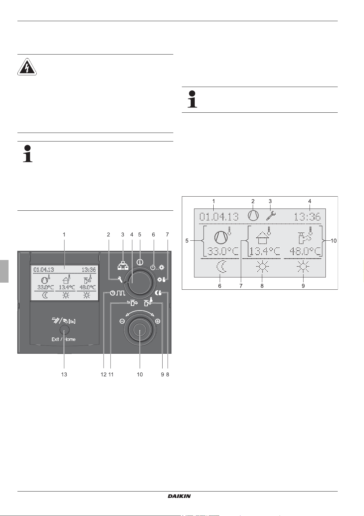
3.2 Display and operating elements
3.2.1 Display
All the operating steps are supported by appropriate displays in a
clear text display on a coloured background.
Menu navigation is available in 7 different languages (see
3.4.8).
section
Malfunctions are generally indicated by a fault code and
a clear text fault message on the display.
For troubleshooting instructions refer to chapter 8.
The colour of the backlighting indicates the operational status
and the operational mode:
White: Standard lighting, normal operational display.
Red: Fault status, depending on the type of fault, the
Daikin Altherma EHS(X/H) continues to function with
restrictions.
Green: Operating mode with operator authorisation.
Blue: Operating mode with expert technician authori-
sation.
1 Clear text display
2 Setting: Configuration
3 Setting: Remote Param
4 Rotary switch
5 Setting: Info
6 Setting: Operating Mode
Fig. 3-1 Arrangement of display and operating elements
7 Setting: Set Temp Day
8 Setting: Set Temp Night
9 Setting: DHW Set Temp
10 Rotary button
11 Setting: DHW Install
12 Setting: Time Program
13 Exit button
1 Date display
2 Status of refrigerant com-
pressor
3 Status display (e.g. Techni-
cian access rights active)
4 Display time
5 Current flow temperature
6 Status heating circuit
Fig. 3-2 Display of the Controller - standard display
7 Current outdoor temperature
8 Active operating mode
9 Status of hot water genera-
tion
10 Current storage tank temper-
ature
Operating instructions
12
Daikin Altherma EHS(X/H)
Daikin Altherma integrated solar unit
008.1420944 – 05/2014
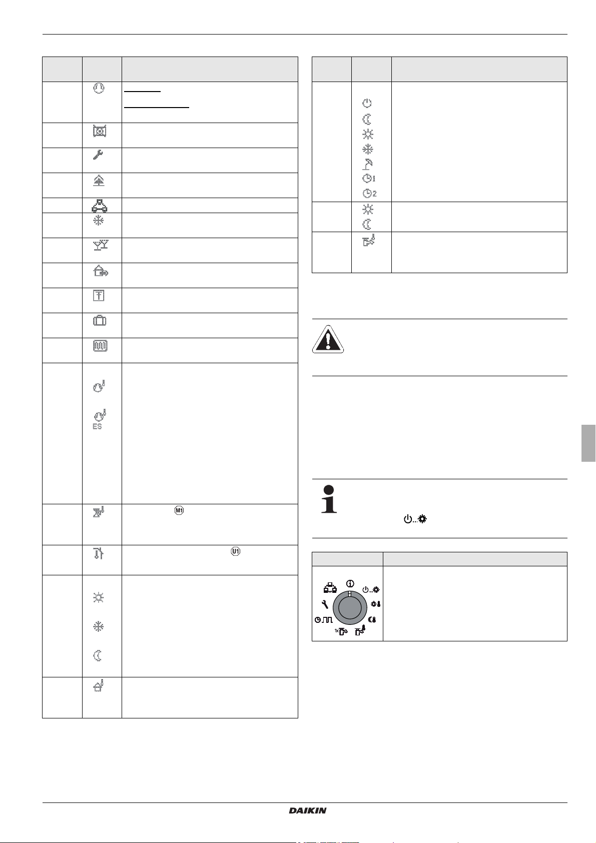
Explanation of symbols
Item
fig. 3-2
2 / 3 Air Purge active (can only be activated by
2 / 3 Terminal function active (see section 3.4.9)
2 / 3 Frost protection function active (see
2 / 3 "Party" temporary timer programme active
2 / 3 "Away" temporary timer programme active
2 / 3 "Holiday" temporary timer programme
2 / 3 "Vacation" temporary timer programme
2 / 3 Screed Program active (can only be acti-
Symbol Explanation
2 Flashing: Heat pump demand active
Permanently on: Refrigerant compressor is
working
2 No connection to the external heat pump
unit
3 Access Rights Expert active (see
3.6.1)
section
the heating technician)
section 3.6.5)
(see section
3.4.7)
(see section 3.4.7)
active (see section 3.4.7)
active (see section
3.4.7)
vated by the heating technician)
5 Direct heating circuit
– Under normal conditions, the current
inflow temperature t
V, BH
is displayed.
– In the case of no demands from the
heat pump, the abbreviation "ES" is
displayed instead of the current inflow
temperature.
The control system has switched to
energy saving mode (see
3.4.2). Superfluous elec-
section
tronic components are switched off.
5 Mixer circuit
The current inflow temperature of the selected heating circuit is displayed.
5 Room temperature sensor
The current room temperature is displayed.
6 Heating circuit status
– Heating circuit active (room heating
function)
3 x Operation
Item
fig. 3-2
Tab. 3-1 Explanation of display symbols
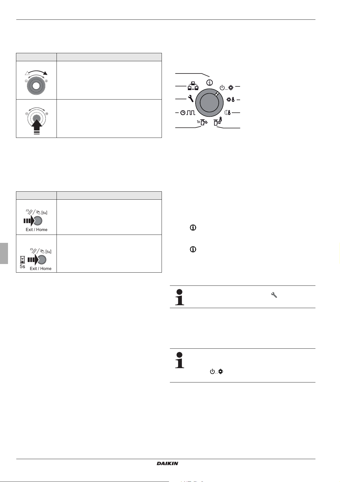
3.2.2 Operating elements
If special key combinations or extended key pushes are required
for certain function, a separate note is made in each specific
section of this description.
Rotary switch
The rotary switch is used to gain rapid direct access (main
function level) to frequently required functions and setting options.
Symbol Explanation
8 Current operating mode (see section 3.4.2)
Standby active
Reducing active
Heating active
Cooling active
Summer active
Automatic 1 active
Automatic 2 active
9 Domestic hot water generation active
Domestic hot water generation not active
10 Domestic hot water circuit status
The current storage tank temperature
t
is displayed.
DHW1
CAUTION!
Never operate the operating elements on the controller with a hard, pointed object. This can cause
damage and can cause the control unit to malfunction.
Independent of the setting of the rotary switch, the
Daikin Altherma EHS(X/H) operates in accordance with
the operating mode set in the switch position "Oper
ating Mode" or which has been activated by a
special programme.
Action Result
Rotating
Direct selection of the main function level allocated to this switch position.
-
– Heating circuit active (room cooling
function)
– Heating circuit not active (currently no
heat transfer in the heating circuit)
7 Outside temperature sensor
The current outside temperature is displayed.
Daikin Altherma EHS(X/H)
Daikin Altherma integrated solar unit
008.1420944 – 05/2014
Tab. 3-2 Function of rotary switch
Operating instructions
13
3 x Operation
1
2
3
45
6
7
8
9
Rotary switch
The rotary switch can be used to navigate in the individual levels,
setting values can be selected, changed and these changes can
then be accepted by pressing briefly.
Action Result
Rotating
To the right (+): Increased regulation
To the left (–): Reduced regulation
Pressing
Confirm, accept, selection and execute the
function.
Tab. 3-3 Functions of the rotary switch
Exit button
This button can be used to jump back to the previous display
within a menu display or a function / input can be interrupted.
This button can also be used to call up the special level (see
3.5).
section
Action Result
Brief pressing.
Pressfor more
than 5 secs.
Tab. 3-4 Functions of the exit button
– Jump back to the previous display or pre-
vious level or
– Cancellation of a special function or an
active temporary timer programme.
– Special level is called up.
3.3 Operating concept
The operating concept for controlling the RoCon HP is structured
in such a way that the frequently required settings options are accessible quickly and directly at the main function level (selection
using the rotary switch), while the less frequently required settings options are arranged at a lower parameter level.
1 Operating Mode (section 3.4.2)
2 Set Temp Day (section 3.4.3)
3 Set Temp Night (section 3.4.4)
4 DHW Set Temp (section 3.4.5)
5 DHW Install (section 3.4.6)
6 Time Program (section 3.4.7)
7 Configuration (section 3.4.8)
8 Remote Param (section 3.4.9)
9 Info (section 3.4.1)
Fig. 3-3 Illustration of main function level (rotary switch position)
Certain functions and parameters are restricted by access authorisation and can only be adjusted by the heating technician
(see Section 3.6.1).
In normal operating mode the rotary switch should be in
position .
After switching on and successful initialisation, the display automatically shows the standard display with rotary switch
position .
In the first commissioning, the setting for language selection is
displayed first.
● Select the language using the rotary switch.
● Confirm the changes with a brief press of the rotary switch.
Adaption to the special installation configuration is
carried out in the "Configuration"
rotary switch
position (see section 3.4.8).
When the system is switched on, based on the stipulations set in
the Controller RoCon HP, it fully automatically regulates the
operation of the
– room heating, room cooling and the
– sanitary hot water generation.
Independent of the setting of the rotary switch, the
Daikin Altherma EHS(X/H) operates in accordance with
the operating mode set in the "Operating
switch position or that has been acti-
Mode"
vated by a special programme.
If the user enters a value manually, this setting remains active
until the user changes it or until the programme clock forces an
-
other operating mode.
Operating instructions
14
Daikin Altherma EHS(X/H)
Daikin Altherma integrated solar unit
008.1420944 – 05/2014
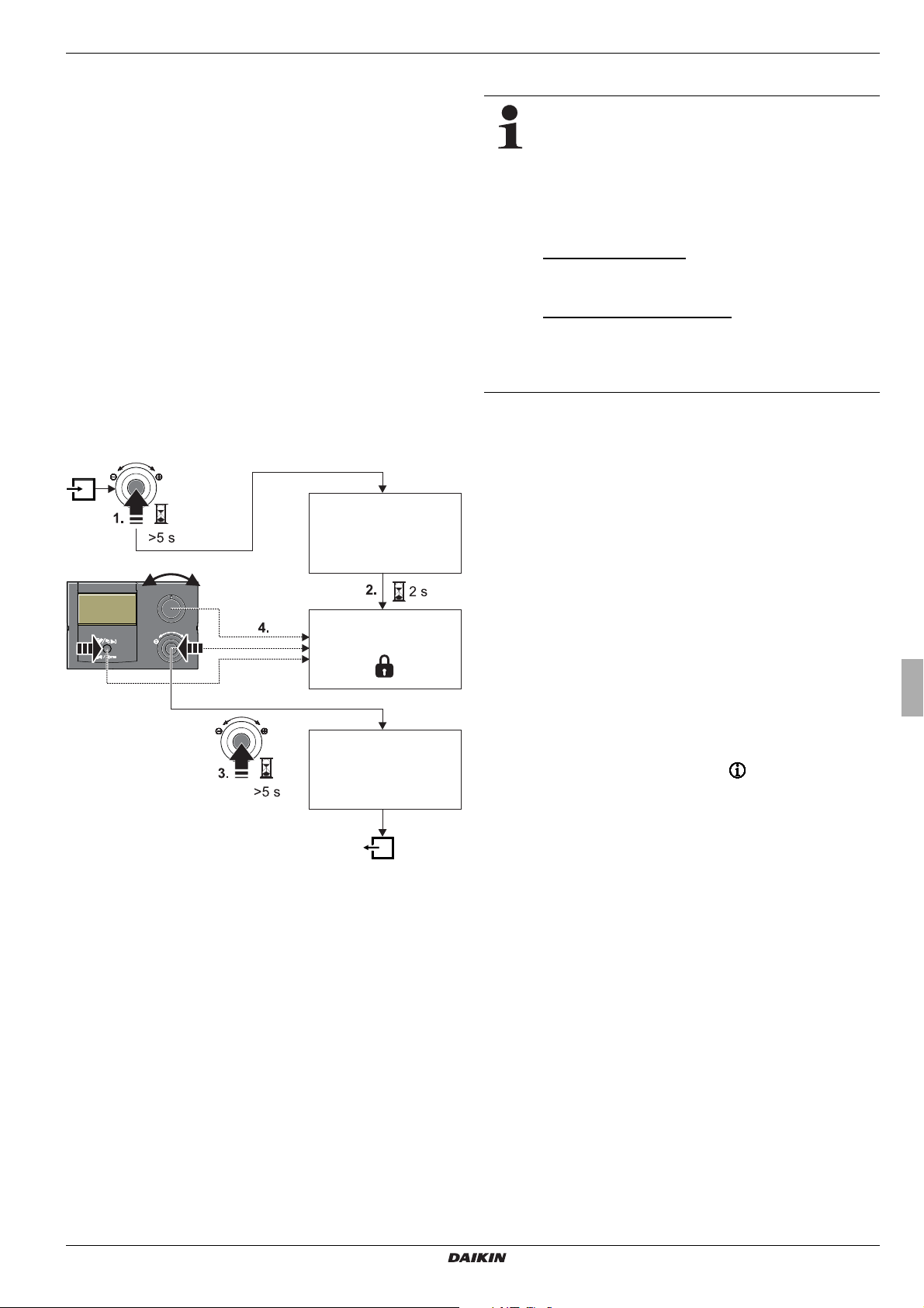
3 x Operation
Keylock Function
On
Keylock Function
Keylock Function
Off
The operating mode can be affected by additional functions such
as:
– Weather-controlled flow temperature regulation
– Switching time program
– Setting the temperature target value
– Setting at the room station
– EXT signal (external operating mode switching)
– Quite Mode
– Interlink fct
– SMART GRID - Signal
– EVU (reduced cost tariff) - Signal
– Screed function
–Air Purge
– Manual Operation
Button block
The operating panel on the RoCon HP can be blocked to prevent
inadvertent actuation (see fig. 3-4).
Unlocking can be carried out in the same way.
The prerequisite for this function is that, in the level "Setup", the
parameter [Keylock Function] is set to "On" (see chapter 6.2.1,
tab. 6-1).
3.4 Basic functions and operating modes
If the storage temperature falls below a certain
minimum value, the safety settings of the Daikin
Altherma EHS(X/H) prevent the operation of the heat
pump in the case of low external temperatures:
– External temperature < -2 °C, minimum storage
temperature = 30 °C
– External temperature < 12 °C, minimum storage
temperature = 23 °C.
Without backup heater:
The storage tank water must be heated to the minimum
required storage temperature by an external heater.
With backup heater (EKBUxx):
With an outdoor temperature < 12 °C and a storage tank
temperature < 35 °C, the backup heater (EKBUxx) is
switched on automatically on in order to heat up the
storage tank water to at least 35
Automatic defrosting function
At low outdoor temperatures and corresponding humidity values,
the external heat pump unit may ice up. This icing impairs efficient operation. The system detects this condition automatically
and starts the defrosting function.
During the defrosting function, heat is drawn from the hot water
storage tank and the backup heater is turned on if required. De
pending on the heat demand for the defrosting function, heating
of the direct heating circuit may be interrupted temporarily.
After 8 minutes at most, the system returns to normal mode.
°C.
-
Fig. 3-4 Activating and deactivating the key lock
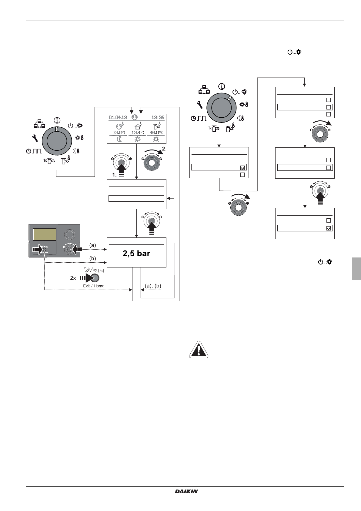
3.4.1 System information (Info)
In this rotary switch position, the rotary switch can be used to call
up all the system temperatures, the type of Daikin Altherma
EHS(X/H), various software information and the operating sta
tuses of all system components, one after the other. The number
of displayed parameters depends on the connected components.
No settings can be made to these values.
● Place the rotary switch in the "Info" position.
Standard display is shown (see fig. 3-2).
● Press the rotary switch briefly.
The parameter overview is displayed.
● Select the desired information level with the rotary switch.
● Confirm the changes with a brief push of the rotary switch.
The value is displayed (for example, see fig. 3-6).
● Select the individual information with the rotary switch.
More detailed explanations and possible setting values for this rotary switch setting
can be seen in chapter
6.10.
Daikin Altherma EHS(X/H)
Daikin Altherma integrated solar unit
008.1420944 – 05/2014
Operating instructions
15
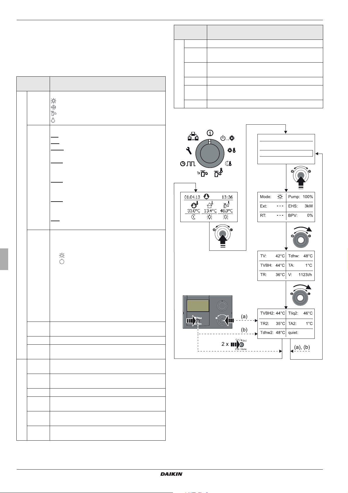
3 x Operation
Info
Overview
Water Pressure
Off
Display operating data overview
The current operating data for the Daikin Altherma EHS(X/H) are
shown on the RoCon HP Controller in the "Overview" information
level.
The display of the operating data is not divided into several
windows. By adjusting the rotary switch it is toggled between the
windows.
Short
designation
Mode Current mode of the heat pump:
Ext Current energy mode of the heat pump:
Page 1
RT Parameter [Room thermostat] / [Interlink fct]
Pump Actual output of the internal heating circulation
EHS Current output of the backup heater in kW
BPV Current position of the mixing valve 3UVB1
TV Current inflow temperature after the plate heat
TVBH Current heating inflow temperature or temp. after
TR Current heating return flow temperature (tR1)
Tdhw Current temperature in domestic hot water
Page 2
TA Actual outdoor temperature (measured by op-
V Actual volume flow (flow rate) in the heating
Explanation of the displayed value
: Heating
: Cooling
: Domestic hot water generation
: Automatic defrosting function active
LT: EVU function active and low tariff.
HT: EVU function active and standard tariff.
SGN: SMART GRID - Function active, normal
mode.
SG1: SMART GRID - Function active, Disconnection: no heat pump operation, no frost
protection function.
SG2: SMART GRID - Function active, Switching
on recommendation, Operation with higher target
temperatures, cheaper electricity.
SG3: SMART GRID - Function active, Command
to switch on and storage tank charging to 70 °C,
cheaper electricity
- - -: No external mode active, heat pump works in
normal mode.
= Off: - - -
Parameter [Room thermostat] = On:
– : Heating or cooling demand
– : No heating demand
Parameter [Interlink fct] = On (priority):
– - - -: Only frost protection
– IL1: Normal inflow target temperature
–IL2:
– Increased inflow target temperature in
heating operation
– Decreased inflow target temperature in
cooling operation
pump in %
(100% = A, 0% = B)
exchanger (t
heating support heat exchanger (t
storage tank (t
V1
)
DHW1
)
V, BH
)
tional temperature sensor RoCon OT1)
system
Short
Explanation of the displayed value
designation
TVBH2 = TVBH
TR2 Current heating return flow temperature, sec-
ondary sensor (tR2)
TDHW2 Current temperature in domestic hot water
storage tank, secondary sensor (t
Page 3
Tliq2 Current coolant temperature (tL2)
DHW2
)
TA2 Actual outdoor temperature (measured by tem-
perature sensor of the external heat pump)
quiet Shows the status of the whisper mode
Tab. 3-5 Description of the operating data displayed as an overview
Fig. 3-5 Display operating data overview
Operating instructions
16
Daikin Altherma EHS(X/H)
Daikin Altherma integrated solar unit
008.1420944 – 05/2014
3 x Operation
Info
Overview
Water Pressure
T-HS
Water Pressure
Operating Mode
Standby
Reducing
Operating Mode
Heating
Cooling
Summer
Operating Mode
Summer
Automatic 1
Automatic 2
Operating Mode
Summer
Automatic 1
Automatic 2
Displaying the water pressure
On the Controller RoCon HP, when it is switched on, you can
display the system pressure (water pressure) in the internal
circuit (direct heating circuit). The water pressure is available as
the first info parameter (see
The permissible range of water pressure during operation depends on the Daikin Altherma EHS(X/H) and the heating system.
The set values and threshold values must only be changed by the
heating technician. If the water pressure falls below the minimum
value (set parameter value), it must be increased by topping up
the system (see chapter on "Inspection and Maintenance").
fig. 3-6).
3.4.2 Setting the operating mode
The selection of the operating mode with which the Daikin
Altherma EHS(X/H) is to operate is undertaken on the rotary
switch in the setting "Operating Mode"
The selected operating mode is activated by briefly pushing the
rotary switch.
.
Fig. 3-6 Info values display (e.g. system pressure)
Fig. 3-7 Switching the operating mode
(e.g.: from "Standby" to "Automatic 1")
● Place the rotary switch in the "Operating Mode"
position.
An overview is displayed.
● Select the desired operating mode with the rotary switch.
● Confirm the changes with a brief push of the rotary switch.
Daikin Altherma EHS(X/H) operates in accordance with
the set operating mode.
The current operating mode is indicated by an appropriate
symbol in the standard display.
Operating mode Standby (Stand-by)
CAUTION!
A heating system that is not frost-protected can freeze
in cold weather and may be damaged.
● Drain the water out of the heating system if there is
a risk of frost.
● If the heating system is not drained and there is a
risk of frost, the power supplies must be secured
and the external main switch must remain switched
on.
In this mode, the Daikin Altherma EHS(X/H) is shifted to the
stand-by mode. The frost-protection function (see
3.6.5) remains in place. In order to maintain this function,
section
the system must not be disconnected from the mains!
All controllers integrated into the RoCon-system via the CAN bus
are also switched at a higher level to the operating mode
"Standby".
Daikin Altherma EHS(X/H)
Daikin Altherma integrated solar unit
008.1420944 – 05/2014
Operating instructions
17
 Loading...