

Daikin EHFZ03S18DJ3V, ERLA03DAV3 Installer reference guide
Installer reference guide
Daikin Altherma 3 R F
EHFZ03S18DJ3V ERLA03DAV3

Table of contents
Table of contents
1 General safety precautions 6
1.1 About the documentation .............................................................................................................................................. 6
1.1.1 Meaning of warnings and symbols ................................................................................................................ 6
1.2 For the installer............................................................................................................................................................... 7
1.2.1 General ........................................................................................................................................................... 7
1.2.2 Installation site ............................................................................................................................................... 8
1.2.3 Refrigerant ...................................................................................................................................................... 9
1.2.4 Brine................................................................................................................................................................ 10
1.2.5 Water .............................................................................................................................................................. 11
1.2.6 Electrical ......................................................................................................................................................... 11
2 About the documentation 14
2.1 About this document ...................................................................................................................................................... 14
2.2 Installer reference guide at a glance .............................................................................................................................. 15
3 About the box 17
3.1 Overview: About the box ................................................................................................................................................ 17
3.2 Outdoor unit ................................................................................................................................................................... 17
3.2.1 To unpack the outdoor unit ........................................................................................................................... 17
3.2.2 To handle the outdoor unit ............................................................................................................................ 18
3.2.3 To remove the accessories from the outdoor unit........................................................................................ 18
3.3 Indoor unit ...................................................................................................................................................................... 18
3.3.1 To unpack the indoor unit .............................................................................................................................. 18
3.3.2 To remove the accessories from the indoor unit .......................................................................................... 19
3.3.3 To handle the indoor unit............................................................................................................................... 19
4 About the units and options 20
4.1 Overview: About the units and options.......................................................................................................................... 20
4.2 Identification ................................................................................................................................................................... 20
4.2.1 Identification label: Outdoor unit .................................................................................................................. 20
4.2.2 Identification label: Indoor unit ..................................................................................................................... 21
4.3 Combining units and options.......................................................................................................................................... 21
4.3.1 Possible combinations of indoor unit and outdoor unit................................................................................ 21
4.3.2 Possible options for the outdoor unit ............................................................................................................ 21
4.3.3 Possible options for the indoor unit............................................................................................................... 22
5 Application guidelines 24
5.1 Overview: Application guidelines ................................................................................................................................... 24
5.2 Setting up the space heating system.............................................................................................................................. 24
5.2.1 Multiple rooms – TwoLWT zones.................................................................................................................. 25
5.3 Setting up the domestic hot water tank......................................................................................................................... 27
5.3.1 System layout – Integrated DHW tank........................................................................................................... 27
5.3.2 Selecting the desired temperature for the DHW tank .................................................................................. 27
5.3.3 Setup and configuration – DHW tank ............................................................................................................ 28
5.3.4 DHW pump for instant hot water .................................................................................................................. 29
5.3.5 DHW pump for disinfection ........................................................................................................................... 29
5.4 Setting up the energy metering...................................................................................................................................... 30
5.4.1 Produced heat ................................................................................................................................................ 30
5.4.2 Consumed energy........................................................................................................................................... 30
5.4.3 Normal kWh rate power supply ..................................................................................................................... 31
5.4.4 Preferential kWh rate power supply .............................................................................................................. 32
5.5 Setting up the power consumption control ................................................................................................................... 33
5.5.1 Permanent power limitation .......................................................................................................................... 33
5.5.2 Power limitation activated by digital inputs .................................................................................................. 34
5.5.3 Power limitation process................................................................................................................................ 35
5.6 Setting up an external temperature sensor ................................................................................................................... 35
Installer reference guide
2
6 Unit installation 37
6.1 Preparing the installation site......................................................................................................................................... 37
6.1.1 Installation site requirements of the outdoor unit........................................................................................ 38
6.1.2 Additional installation site requirements of the outdoor unit in cold climates............................................ 40
6.1.3 Installation site requirements of the indoor unit .......................................................................................... 41
6.2 Opening and closing the units ........................................................................................................................................ 43
6.2.1 About opening the units................................................................................................................................. 43
6.2.2 To open the outdoor unit ............................................................................................................................... 43
6.2.3 To close the outdoor unit ............................................................................................................................... 43
ERLA03DAV3 + EHFZ03S18DJ3V
Daikin Altherma 3 R F
4P596821-1 – 2019.10

Table of contents
6.2.4 To open the indoor unit ................................................................................................................................. 44
6.2.5 To lower the switch box on the indoor unit .................................................................................................. 46
6.2.6 To close the indoor unit ................................................................................................................................. 46
6.3 Mounting the outdoor unit............................................................................................................................................. 47
6.3.1 About mounting the outdoor unit ................................................................................................................. 47
6.3.2 Precautions when mounting the outdoor unit .............................................................................................. 47
6.3.3 To provide the installation structure ............................................................................................................. 47
6.3.4 To install the outdoor unit ............................................................................................................................. 48
6.3.5 To provide drainage........................................................................................................................................ 48
6.3.6 To prevent the outdoor unit from falling over .............................................................................................. 49
6.4 Mounting the indoor unit ............................................................................................................................................... 50
6.4.1 About mounting the indoor unit .................................................................................................................... 50
6.4.2 Precautions when mounting the indoor unit................................................................................................. 50
6.4.3 To install the indoor unit ................................................................................................................................ 50
6.4.4 To connect the drain hose to the drain ......................................................................................................... 51
6.5 Finishing the outdoor unit installation ........................................................................................................................... 52
6.5.1 To finish the outdoor unit installation ........................................................................................................... 52
7 Piping installation 53
7.1 Preparing refrigerant piping ........................................................................................................................................... 53
7.1.1 Refrigerant piping requirements.................................................................................................................... 53
7.1.2 Refrigerant piping insulation .......................................................................................................................... 54
7.2 Preparing water piping ................................................................................................................................................... 54
7.2.1 Water circuit requirements............................................................................................................................ 54
7.2.2 Formula to calculate the expansion vessel pre-pressure .............................................................................. 57
7.2.3 To check the water volume and flow rate ..................................................................................................... 57
7.2.4 Changing the pre-pressure of the expansion vessel...................................................................................... 59
7.2.5 To check the water volume: Examples .......................................................................................................... 60
7.3 Connecting the refrigerant piping .................................................................................................................................. 60
7.3.1 About connecting the refrigerant piping ....................................................................................................... 60
7.3.2 Precautions when connecting the refrigerant piping .................................................................................... 61
7.3.3 Guidelines when connecting the refrigerant piping ...................................................................................... 62
7.3.4 Pipe bending guidelines ................................................................................................................................. 62
7.3.5 To flare the pipe end ...................................................................................................................................... 62
7.3.6 To braze the pipe end..................................................................................................................................... 63
7.3.7 Using the stop valve and service port ............................................................................................................ 64
7.3.8 To connect the refrigerant piping to the outdoor unit ................................................................................. 65
7.3.9 To connect the refrigerant piping to the indoor unit .................................................................................... 66
7.4 Checking the refrigerant piping...................................................................................................................................... 66
7.4.1 About checking the refrigerant piping ........................................................................................................... 66
7.4.2 Precautions when checking the refrigerant piping........................................................................................ 67
7.4.3 To check for leaks ........................................................................................................................................... 67
7.4.4 To perform vacuum drying............................................................................................................................. 68
7.5 Charging refrigerant........................................................................................................................................................ 69
7.5.1 About charging refrigerant............................................................................................................................. 69
7.5.2 About the refrigerant ..................................................................................................................................... 69
7.5.3 Precautions when charging refrigerant ......................................................................................................... 70
7.5.4 To determine the complete recharge amount .............................................................................................. 70
7.5.5 To fix the fluorinated greenhouse gases label ............................................................................................... 70
7.6 Connecting water piping................................................................................................................................................. 71
7.6.1 About connecting the water piping ............................................................................................................... 71
7.6.2 Precautions when connecting the water piping ............................................................................................ 71
7.6.3 To connect the water piping .......................................................................................................................... 71
7.6.4 To connect the recirculation piping ............................................................................................................... 73
7.6.5 To fill the water circuit ................................................................................................................................... 74
7.6.6 To fill the domestic hot water tank ................................................................................................................ 74
7.6.7 To insulate the water piping .......................................................................................................................... 74
ERLA03DAV3 + EHFZ03S18DJ3V
Daikin Altherma 3 R F
4P596821-1 – 2019.10
8 Electrical installation 75
8.1 About connecting the electrical wiring .......................................................................................................................... 75
8.1.1 Precautions when connecting the electrical wiring....................................................................................... 75
8.1.2 Guidelines when connecting the electrical wiring......................................................................................... 76
8.1.3 Specifications of standard wiring components.............................................................................................. 77
8.1.4 About electrical compliance........................................................................................................................... 78
8.1.5 About preferential kWh rate power supply ................................................................................................... 78
8.1.6 Overview of electrical connections except external actuators ..................................................................... 79
8.2 Connections to the outdoor unit.................................................................................................................................... 79
8.2.1 To connect the electrical wiring to the outdoor unit .................................................................................... 79
8.3 Connections to the indoor unit ...................................................................................................................................... 80
8.3.1 To connect the main power supply................................................................................................................ 82
Installer reference guide
3

Table of contents
8.3.2 To connect the backup heater power supply ................................................................................................ 84
8.3.3 To connect the user interface ........................................................................................................................ 86
8.3.4 To connect the shut-off valve ........................................................................................................................ 87
8.3.5 To connect the electricity meters .................................................................................................................. 88
8.3.6 To connect the domestic hot water pump .................................................................................................... 89
8.3.7 To connect the alarm output ......................................................................................................................... 90
8.3.8 To connect the space heating ON/OFF output .............................................................................................. 91
8.3.9 To connect the changeover to external heat source..................................................................................... 92
8.3.10 To connect the power consumption digital inputs........................................................................................ 93
8.3.11 To connect the safety thermostat (normally closed contact)....................................................................... 94
8.4 After connecting the electrical wiring to the indoor unit .............................................................................................. 96
9 Configuration 98
9.1 Overview: Configuration................................................................................................................................................. 98
9.1.1 To change the user permission level ............................................................................................................. 99
9.1.2 To access the most used commands ............................................................................................................. 99
9.1.3 To copy the system settings from the first to the second user interface ..................................................... 101
9.1.4 Quick wizard: Set the system layout after first power ON ............................................................................ 102
9.2 Basic configuration.......................................................................................................................................................... 103
9.2.1 Quick wizard: Language / time and date ....................................................................................................... 103
9.2.2 Quick wizard: Standard .................................................................................................................................. 103
9.2.3 Quick wizard: Options .................................................................................................................................... 106
9.2.4 Space heating/cooling control ....................................................................................................................... 110
9.2.5 Domestic hot water control ........................................................................................................................... 113
9.2.6 Contact/helpdesk number ............................................................................................................................. 113
9.3 Weather-dependent curve ............................................................................................................................................. 114
9.3.1 What is a weather-dependent curve? ........................................................................................................... 114
9.3.2 2-points curve ................................................................................................................................................. 114
9.3.3 Using weather-dependent curves.................................................................................................................. 115
9.4 Advanced configuration/optimisation............................................................................................................................ 116
9.4.1 Space heating/cooling operation: advanced ................................................................................................. 116
9.4.2 Domestic hot water control: advanced ......................................................................................................... 123
9.4.3 Heat source settings ....................................................................................................................................... 128
9.4.4 System settings ............................................................................................................................................... 131
9.5 Menu structure: Overview user settings........................................................................................................................ 139
9.6 Menu structure: Overview installer settings.................................................................................................................. 140
10 Commissioning 141
10.1 Overview: Commissioning .............................................................................................................................................. 141
10.2 Precautions when commissioning .................................................................................................................................. 141
10.3 Checklist before commissioning ..................................................................................................................................... 142
10.4 Checklist during commissioning ..................................................................................................................................... 143
10.4.1 To check the minimum flow rate ................................................................................................................... 143
10.4.2 Air purge function........................................................................................................................................... 144
10.4.3 To perform a test run ..................................................................................................................................... 145
10.4.4 To perform an actuator test run .................................................................................................................... 146
10.4.5 Underfloor heating screed dryout ................................................................................................................. 146
11 Hand-over to the user 150
12 Maintenance and service 151
12.1 Overview: Maintenance and service .............................................................................................................................. 151
12.2 Maintenance safety precautions .................................................................................................................................... 151
12.3 Checklist for yearly maintenance of the outdoor unit ................................................................................................... 152
12.4 Checklist for yearly maintenance of the indoor unit ..................................................................................................... 152
12.4.1 To drain the domestic hot water tank ........................................................................................................... 155
12.5 About cleaning the water filter in case of trouble ......................................................................................................... 156
12.5.1 To remove the water filter ............................................................................................................................. 156
12.5.2 To clean the water filter in case of trouble.................................................................................................... 156
12.5.3 To install the water filter................................................................................................................................ 158
13 Troubleshooting 159
13.1 Overview: Troubleshooting ............................................................................................................................................ 159
13.2 Precautions when troubleshooting ................................................................................................................................ 159
13.3 Solving problems based on symptoms ........................................................................................................................... 160
13.3.1 Symptom: The unit is NOT heating as expected............................................................................................ 160
13.3.2 Symptom: The compressor does NOT start (space heating or domestic water heating) ............................ 161
13.3.3 Symptom: The system is making gurgling noises after commissioning ........................................................ 161
13.3.4 Symptom: The pump is blocked..................................................................................................................... 162
13.3.5 Symptom: The pump is making noise (cavitation)......................................................................................... 162
13.3.6 Symptom: The pressure relief valve opens.................................................................................................... 162
Installer reference guide
4
ERLA03DAV3 + EHFZ03S18DJ3V
Daikin Altherma 3 R F
4P596821-1 – 2019.10

Table of contents
13.3.7 Symptom: The water pressure relief valve leaks........................................................................................... 163
13.3.8 Symptom: The space is NOT sufficiently heated at low outdoor temperatures........................................... 164
13.3.9 Symptom: The pressure at the tapping point is temporarily unusually high................................................ 165
13.3.10 Symptom: Decoration panels are pushed away due to a swollen tank ........................................................ 165
13.3.11 Symptom: Tank disinfection function is NOT completed correctly (AH-error) ............................................. 165
13.4 Solving problems based on error codes ......................................................................................................................... 165
13.4.1 Error codes: Overview.................................................................................................................................... 166
14 Disposal 173
14.1 Overview: Disposal.......................................................................................................................................................... 173
14.2 To pump down ................................................................................................................................................................ 173
15 Technical data 175
15.1 Piping diagram: Outdoor unit ......................................................................................................................................... 175
15.2 Piping diagram: Indoor unit ............................................................................................................................................ 176
15.3 Wiring diagram: Outdoor unit ........................................................................................................................................ 177
15.4 Wiring diagram: Indoor unit ........................................................................................................................................... 179
16 Glossary 185
17 Field settings table 187
ERLA03DAV3 + EHFZ03S18DJ3V
Daikin Altherma 3 R F
4P596821-1 – 2019.10
Installer reference guide
5
1 | General safety precautions
1 General safety precautions
In this chapter
1.1 About the documentation...................................................................................................................................................... 6
1.2 For the installer....................................................................................................................................................................... 7
1.1 About the documentation
▪ The original documentation is written in English. All other languages are
translations.
▪ The precautions described in this document cover very important topics, follow
them carefully.
1.1.1 Meaning of warnings and symbols ........................................................................................................................ 6
1.2.1 General ................................................................................................................................................................... 7
1.2.2 Installation site ....................................................................................................................................................... 8
1.2.3 Refrigerant.............................................................................................................................................................. 9
1.2.4 Brine ....................................................................................................................................................................... 10
1.2.5 Water ...................................................................................................................................................................... 11
1.2.6 Electrical ................................................................................................................................................................. 11
▪ The installation of the system, and all activities described in the installation
manual and in the installer reference guide MUST be performed by an authorised
installer.
1.1.1 Meaning of warnings and symbols
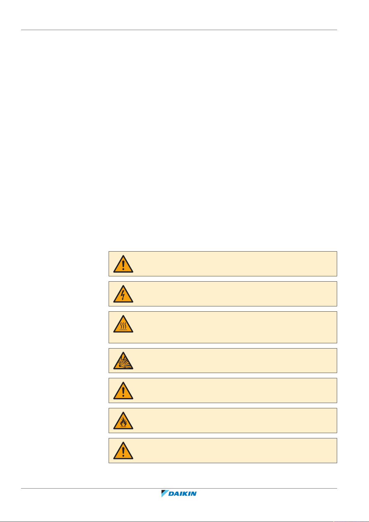
DANGER
Indicates a situation that results in death or serious injury.
DANGER: RISK OF ELECTROCUTION
Indicates a situation that could result in electrocution.
DANGER: RISK OF BURNING
Indicates a situation that could result in burning because of extreme hot or cold
temperatures.
DANGER: RISK OF EXPLOSION
Indicates a situation that could result in explosion.
Installer reference guide
6
WARNING
Indicates a situation that could result in death or serious injury.
WARNING: FLAMMABLE MATERIAL
CAUTION
Indicates a situation that could result in minor or moderate injury.
ERLA03DAV3 + EHFZ03S18DJ3V
Daikin Altherma 3 R F
4P596821-1 – 2019.10
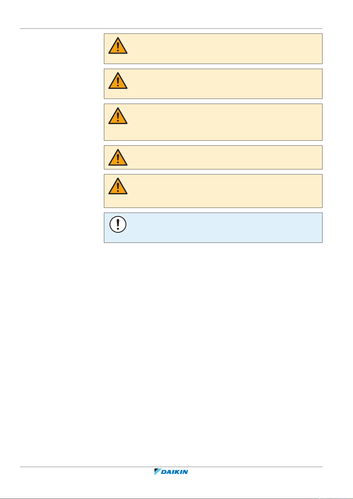
NOTICE
Indicates a situation that could result in equipment or property damage.
INFORMATION
Indicates useful tips or additional information.
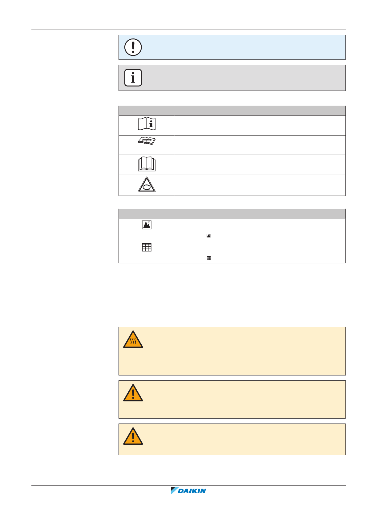
Symbols used on the unit:
Symbol Explanation
Before installation, read the installation and operation
manual, and the wiring instruction sheet.
Before performing maintenance and service tasks, read the
service manual.
For more information, see the installer and user reference
guide.
The unit contains rotating parts. Be careful when servicing or
inspecting the unit.
1 | General safety precautions
Symbols used in the documentation:
1.2 For the installer
1.2.1 General
If you are NOT sure how to install or operate the unit, contact your dealer.
Symbol Explanation
Indicates a figure title or a reference to it.
Example: " 1–3 Figure title" means "Figure 3 in chapter 1".
Indicates a table title or a reference to it.
Example: " 1–3 Table title" means "Table 3 in chapter 1".
DANGER: RISK OF BURNING
▪ Do NOT touch the refrigerant piping, water piping or internal parts during and
immediately after operation. It could be too hot or too cold. Give it time to return
to normal temperature. If you must touch it, wear protective gloves.
▪ Do NOT touch any accidental leaking refrigerant.
ERLA03DAV3 + EHFZ03S18DJ3V
Daikin Altherma 3 R F
4P596821-1 – 2019.10
WARNING
Improper installation or attachment of equipment or accessories could result in
electric shock, short-circuit, leaks, fire or other damage to the equipment. Only use
accessories, optional equipment and spare parts made or approved by Daikin.
WARNING
Make sure installation, testing and applied materials comply with applicable
legislation (on top of the instructions described in the Daikin documentation).
Installer reference guide
7
1 | General safety precautions
CAUTION
Wear adequate personal protective equipment (protective gloves, safety glasses,…)
when installing, maintaining or servicing the system.
WARNING
Tear apart and throw away plastic packaging bags so that nobody, especially
children, can play with them. Possible risk: suffocation.
WARNING
Provide adequate measures to prevent that the unit can be used as a shelter by small
animals. Small animals that make contact with electrical parts can cause
malfunctions, smoke or fire.
CAUTION
Do NOT touch the air inlet or aluminium fins of the unit.
CAUTION
▪ Do NOT place any objects or equipment on top of the unit.
▪ Do NOT sit, climb or stand on the unit.
1.2.2 Installation site
NOTICE
Works executed on the outdoor unit are best done under dry weather conditions to
avoid water ingress.
In accordance with the applicable legislation, it might be necessary to provide a
logbook with the product containing at least: information on maintenance, repair
work, results of tests, stand-by periods,…
Also, at least, following information MUST be provided at an accessible place at the
product:
▪ Instructions for shutting down the system in case of an emergency
▪ Name and address of fire department, police and hospital
▪ Name, address and day and night telephone numbers for obtaining service
In Europe, EN378 provides the necessary guidance for this logbook.
▪ Provide sufficient space around the unit for servicing and air circulation.
▪ Make sure the installation site withstands the weight and vibration of the unit.
▪ Make sure the area is well ventilated. Do NOT block any ventilation openings.
▪ Make sure the unit is level.
Installer reference guide
8
Do NOT install the unit in the following places:
▪ In potentially explosive atmospheres.
▪ In places where there is machinery that emits electromagnetic waves.
Electromagnetic waves may disturb the control system, and cause malfunction of
the equipment.
▪ In places where there is a risk of fire due to the leakage of flammable gases
(example: thinner or gasoline), carbon fibre, ignitable dust.
ERLA03DAV3 + EHFZ03S18DJ3V
Daikin Altherma 3 R F
4P596821-1 – 2019.10
1.2.3 Refrigerant
1 | General safety precautions
▪ In places where corrosive gas (example: sulphurous acid gas) is produced.
Corrosion of copper pipes or soldered parts may cause the refrigerant to leak.
If applicable. See the installation manual or installer reference guide of your
application for more information.
NOTICE
Make sure refrigerant piping installation complies with applicable legislation. In
Europe, EN378 is the applicable standard.
NOTICE
Make sure the field piping and connections are NOT subjected to stress.
WARNING
During tests, NEVER pressurize the product with a pressure higher than the
maximum allowable pressure (as indicated on the nameplate of the unit).
WARNING
Take sufficient precautions in case of refrigerant leakage. If refrigerant gas leaks,
ventilate the area immediately. Possible risks:
▪ Excessive refrigerant concentrations in a closed room can lead to oxygen
deficiency.
▪ In case of R410A or R32 refrigerant: Toxic gas might be produced if refrigerant
gas comes into contact with fire.
▪ In case of CO
refrigerant: Refrigerant gas is toxic in high concentrations.
2
DANGER: RISK OF EXPLOSION
Pump down – Refrigerant leakage. If you want to pump down the system, and there
is a leak in the refrigerant circuit:
▪ Do NOT use the unit's automatic pump down function, with which you can collect
all refrigerant from the system into the outdoor unit. Possible consequence: Selfcombustion and explosion of the compressor because of air going into the
operating compressor.
▪ Use a separate recovery system so that the unit's compressor does NOT have to
operate.
WARNING
ALWAYS recover the refrigerant. Do NOT release them directly into the environment.
Use a vacuum pump to evacuate the installation.
ERLA03DAV3 + EHFZ03S18DJ3V
Daikin Altherma 3 R F
4P596821-1 – 2019.10
NOTICE
After all the piping has been connected, make sure there is no gas leak. Use nitrogen
to perform a gas leak detection.
Installer reference guide
9
1 | General safety precautions
▪ In case recharge is required, see the nameplate of the unit. It states the type of
refrigerant and necessary amount.
▪ The unit is factory charged with refrigerant and depending on pipe sizes and pipe
lengths some systems require additional charging of refrigerant.
▪ Only use tools exclusively for the refrigerant type used in the system, this to
ensure pressure resistance and prevent foreign materials from entering into the
system.
NOTICE
▪ To avoid compressor breakdown, do NOT charge more than the specified amount
of refrigerant.
▪ When the refrigerant system is to be opened, refrigerant MUST be treated
according to the applicable legislation.
WARNING
Make sure there is no oxygen in the system. Refrigerant may only be charged after
performing the leak test and the vacuum drying.
Possible consequence: Self-combustion and explosion of the compressor because of
oxygen going into the operating compressor.
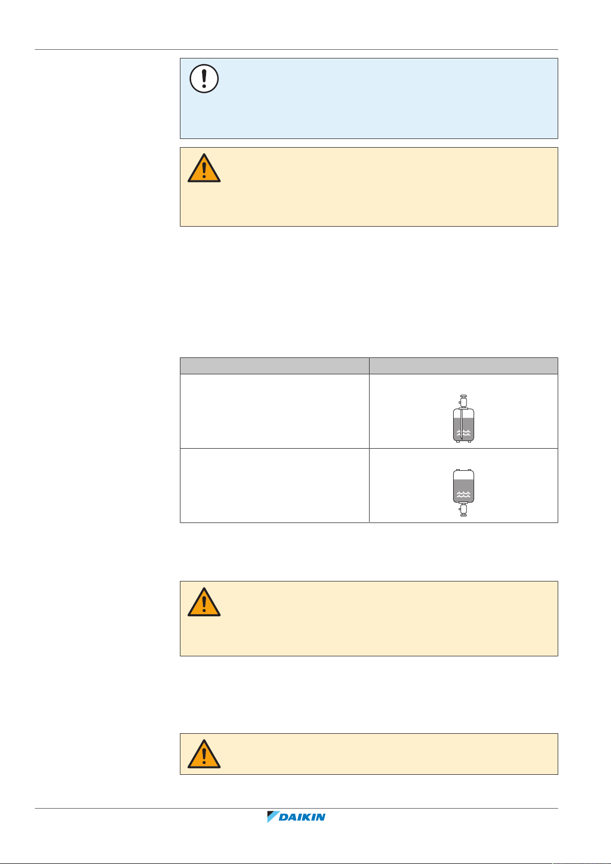
▪ Charge the liquid refrigerant as follows:
If Then
A siphon tube is present
Charge with the cylinder upright.
(i.e., the cylinder is marked with "Liquid
filling siphon attached")
A siphon tube is NOT present Charge with the cylinder upside down.
▪ Open refrigerant cylinders slowly.
▪ Charge the refrigerant in liquid form. Adding it in gas form may prevent normal
operation.
CAUTION
When the refrigerant charging procedure is done or when pausing, close the valve of
the refrigerant tank immediately. If the valve is NOT closed immediately, remaining
pressure might charge additional refrigerant. Possible consequence: Incorrect
refrigerant amount.
1.2.4 Brine
Installer reference guide
10
If applicable. See the installation manual or installer reference guide of your
application for more information.
WARNING
The selection of the brine MUST be in accordance with the applicable legislation.
ERLA03DAV3 + EHFZ03S18DJ3V
Daikin Altherma 3 R F
4P596821-1 – 2019.10
1.2.5 Water
1 | General safety precautions
WARNING
Take sufficient precautions in case of brine leakage. If brine leaks, ventilate the area
immediately and contact your local dealer.
WARNING
The ambient temperature inside the unit can get much higher than that of the room,
e.g. 70°C. In case of a brine leak, hot parts inside the unit can create a hazardous
situation.
WARNING
The use and installation of the application MUST comply with the safety and
environmental precautions specified in the applicable legislation.
If applicable. See the installation manual or installer reference guide of your
application for more information.
NOTICE
Make sure water quality complies with EU directive 98/83EC.
1.2.6 Electrical
DANGER: RISK OF ELECTROCUTION
▪ Turn OFF all power supply before removing the switch box cover, connecting
electrical wiring or touching electrical parts.
▪ Disconnect the power supply for more than 1minute, and measure the voltage at
the terminals of main circuit capacitors or electrical components before servicing.
The voltage MUST be less than 50 V DC before you can touch electrical
components. For the location of the terminals, see the wiring diagram.
▪ Do NOT touch electrical components with wet hands.
▪ Do NOT leave the unit unattended when the service cover is removed.
WARNING
If NOT factory installed, a main switch or other means for disconnection, having a
contact separation in all poles providing full disconnection under overvoltage
categoryIII condition, MUST be installed in the fixed wiring.
ERLA03DAV3 + EHFZ03S18DJ3V
Daikin Altherma 3 R F
4P596821-1 – 2019.10
Installer reference guide
11
1 | General safety precautions
WARNING
▪ ONLY use copper wires.
▪ Make sure the field wiring complies with the applicable legislation.
▪ All field wiring MUST be performed in accordance with the wiring diagram
supplied with the product.
▪ NEVER squeeze bundled cables and make sure they do NOT come in contact with
the piping and sharp edges. Make sure no external pressure is applied to the
terminal connections.
▪ Make sure to install earth wiring. Do NOT earth the unit to a utility pipe, surge
absorber, or telephone earth. Incomplete earth may cause electrical shock.
▪ Make sure to use a dedicated power circuit. NEVER use a power supply shared by
another appliance.
▪ Make sure to install the required fuses or circuit breakers.
▪ Make sure to install an earth leakage protector. Failure to do so may cause
electric shock or fire.
▪ When installing the earth leakage protector, make sure it is compatible with the
inverter (resistant to high frequency electric noise) to avoid unnecessary opening
of the earth leakage protector.
CAUTION
▪ When connecting the power supply: connect the earth cable first, before making
the current-carrying connections.
▪ When disconnecting the power supply: disconnect the current-carrying cables
first, before separating the earth connection.
▪ The length of the conductors between the power supply stress relief and the
terminal block itself must be as such that the current-carrying wires are tautened
before the earth wire is in case the power supply is pulled loose from the stress
relief.
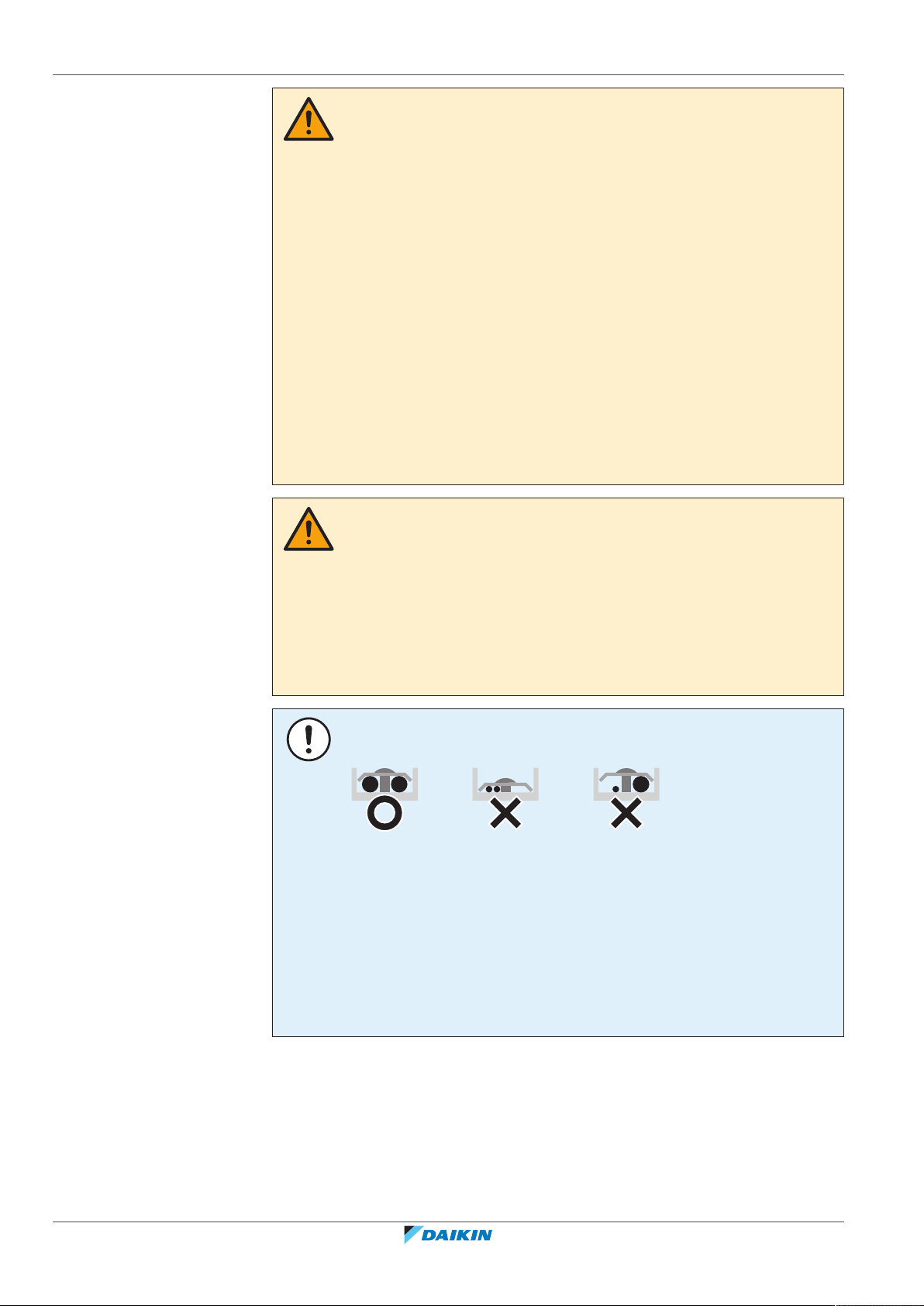
NOTICE
Precautions when laying power wiring:
▪ Do NOT connect wiring of different thicknesses to the power terminal block (slack
in the power wiring may cause abnormal heat).
▪ When connecting wiring which is the same thickness, do as shown in the figure
above.
▪ For wiring, use the designated power wire and connect firmly, then secure to
prevent outside pressure being exerted on the terminal board.
▪ Use an appropriate screwdriver for tightening the terminal screws. A screwdriver
with a small head will damage the head and make proper tightening impossible.
▪ Over-tightening the terminal screws may break them.
Installer reference guide
12
Install power cables at least 1 m away from televisions or radios to prevent
interference. Depending on the radio waves, a distance of 1 m may not be
sufficient.
ERLA03DAV3 + EHFZ03S18DJ3V
Daikin Altherma 3 R F
4P596821-1 – 2019.10

1 | General safety precautions
WARNING
▪ After finishing the electrical work, confirm that each electrical component and
terminal inside the electrical components box is connected securely.
▪ Make sure all covers are closed before starting up the unit.
NOTICE
Only applicable if the power supply is three‑phase, and the compressor has an ON/
OFF starting method.
If there exists the possibility of reversed phase after a momentary black out and the
power goes on and off while the product is operating, attach a reversed phase
protection circuit locally. Running the product in reversed phase can break the
compressor and other parts.
ERLA03DAV3 + EHFZ03S18DJ3V
Daikin Altherma 3 R F
4P596821-1 – 2019.10
Installer reference guide
13

2 | About the documentation
2 About the documentation
In this chapter
2.1 About this document.............................................................................................................................................................. 14
2.2 Installer reference guide at a glance...................................................................................................................................... 15
2.1 About this document
Target audience
Authorised installers
Documentation set
This document is part of a documentation set. The complete set consists of:
▪ General safety precautions:
- Safety instructions that you must read before installing
- Format: Paper (in the box of the indoor unit)
▪ Operation manual:
- Quick guide for basic usage
- Format: Paper (in the box of the indoor unit)
▪ User reference guide:
- Detailed step-by-step instructions and background information for basic and
advanced usage
- Format: Digital files on http://www.daikineurope.com/support-and-manuals/
product-information/
▪ Installation manual – Outdoor unit:
- Installation instructions
- Format: Paper (in the box of the outdoor unit)
▪ Installation manual – Indoor unit:
- Installation instructions
- Format: Paper (in the box of the indoor unit)
▪ Installer reference guide:
- Preparation of the installation, good practices, reference data,…
- Format: Digital files on http://www.daikineurope.com/support-and-manuals/
product-information/
▪ Addendum book for optional equipment:
Installer reference guide
14
- Additional info about how to install optional equipment
- Format: Paper (in the box of the indoor unit) + Digital files on http://
www.daikineurope.com/support-and-manuals/product-information/
Latest revisions of the supplied documentation may be available on the regional
Daikin website or via your dealer.
The original documentation is written in English. All other languages are
translations.
ERLA03DAV3 + EHFZ03S18DJ3V
Daikin Altherma 3 R F
4P596821-1 – 2019.10
2 | About the documentation
Technical engineering data
▪ A subset of the latest technical data is available on the regional Daikin website
(publicly accessible).
▪ The full set of latest technical data is available on the Daikin Business Portal
(authentication required).
Online tools
In addition to the documentation set, some online tools are available for installers:
▪ Heating Solutions Navigator
- Digital toolbox that offers a variety of tools to facilitate the installation and
configuration of heating systems.
- To access Heating Solutions Navigator, registration to the Stand By Me
platform is required. For more information, see https://
professional.standbyme.daikin.eu.
▪ Daikin e-Care
- Mobile app for installers and service technicians that allows you to register,
configure and troubleshoot heating systems.
- The mobile app can be downloaded for iOS and Android devices using the QR
codes below. Registration to the Stand By Me platform is required to access
the app.
App Store Google Play
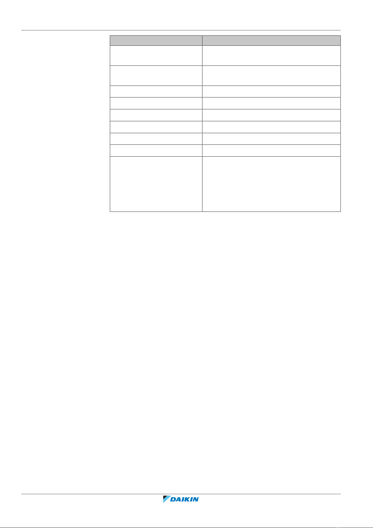
2.2 Installer reference guide at a glance
Chapter Description
General safety precautions Safety instructions that you must read before
installing
About the documentation What documentation exists for the installer
About the box How to unpack the units and remove their
accessories
About the units and options ▪ How to identify the units
▪ Possible combinations of units and options
Application guidelines Various installation setups of the system
Unit installation What to do and know to install the system,
including information on how to prepare for an
installation
ERLA03DAV3 + EHFZ03S18DJ3V
Daikin Altherma 3 R F
4P596821-1 – 2019.10
Piping installation What to do and know to install the piping of the
system, including information on how to
prepare for an installation
Electrical installation What to do and know to install the electrical
components of the system, including
information on how to prepare for an
installation
Installer reference guide
15
2 | About the documentation
Configuration What to do and know to configure the system
Commissioning What to do and know to commission the system
Hand‑over to the user What to give and explain to the user
Maintenance and service How to maintain and service the units
Troubleshooting What to do in case of problems
Disposal How to dispose of the system
Technical data Specifications of the system
Glossary Definition of terms
Field settings table Table to be filled in by the installer, and kept for
Chapter Description
after it is installed
after it is configured
future reference
Note: There is also an installer settings table in
the user reference guide. This table has to be
filled in by the installer and handed over to the
user.
Installer reference guide
16
ERLA03DAV3 + EHFZ03S18DJ3V
Daikin Altherma 3 R F
4P596821-1 – 2019.10
3 About the box
2
3
1
In this chapter
3.1 Overview: About the box........................................................................................................................................................ 17
3.2 Outdoor unit ........................................................................................................................................................................... 17
3.2.1 To unpack the outdoor unit ................................................................................................................................... 17
3.2.2 To handle the outdoor unit.................................................................................................................................... 18
3.2.3 To remove the accessories from the outdoor unit ............................................................................................... 18
3.3 Indoor unit .............................................................................................................................................................................. 18
3.3.1 To unpack the indoor unit...................................................................................................................................... 18
3.3.2 To remove the accessories from the indoor unit .................................................................................................. 19
3.3.3 To handle the indoor unit ...................................................................................................................................... 19
3.1 Overview: About the box
This chapter describes what you have to do after the boxes with the outdoor and
indoor unit are delivered on-site.
Keep the following in mind:
▪ At delivery, the unit MUST be checked for damage. Any damage MUST be
reported immediately to the claims agent of the carrier.
3 | About the box
▪ Bring the packed unit as close as possible to its final installation position to
prevent damage during transport.
▪ When handling the unit, take into account the following:
▪ Prepare the path along which you want to bring the unit inside in advance.
3.2 Outdoor unit
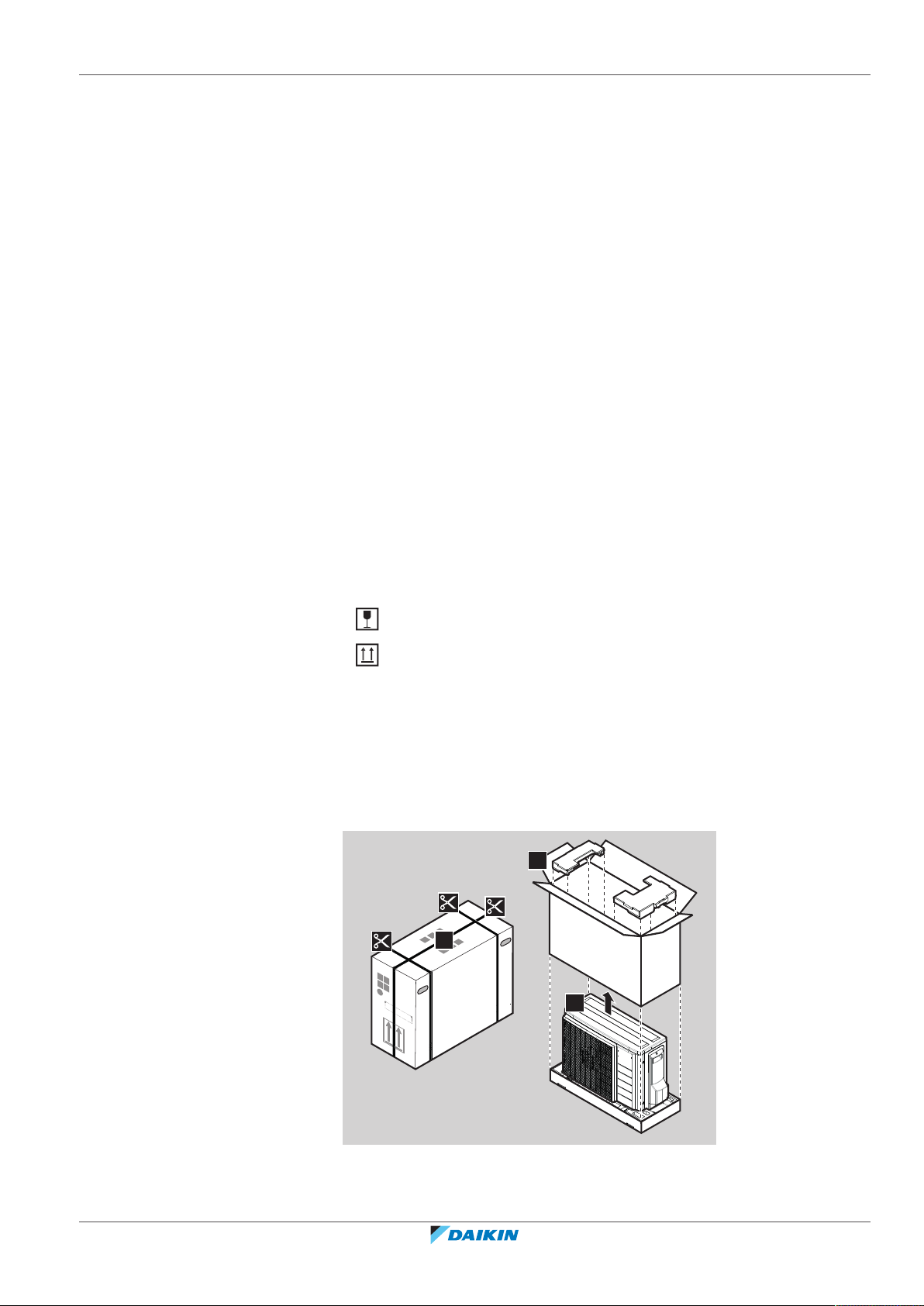
3.2.1 To unpack the outdoor unit
Fragile, handle the unit with care.
Keep the unit upright in order to avoid damage.
ERLA03DAV3 + EHFZ03S18DJ3V
Daikin Altherma 3 R F
4P596821-1 – 2019.10
Installer reference guide
17
3 | About the box
a b c d e
1 2
8×
3.2.2 To handle the outdoor unit
CAUTION
To avoid injury, do NOT touch the air inlet or aluminium fins of the unit.
3.2.3 To remove the accessories from the outdoor unit
a Outdoor unit installation manual
b Multilingual fluorinated greenhouse gases label
c Drain plug (located on the bottom of the packing case)
d Energy label
e Fluorinated greenhouse gases label
3.3 Indoor unit
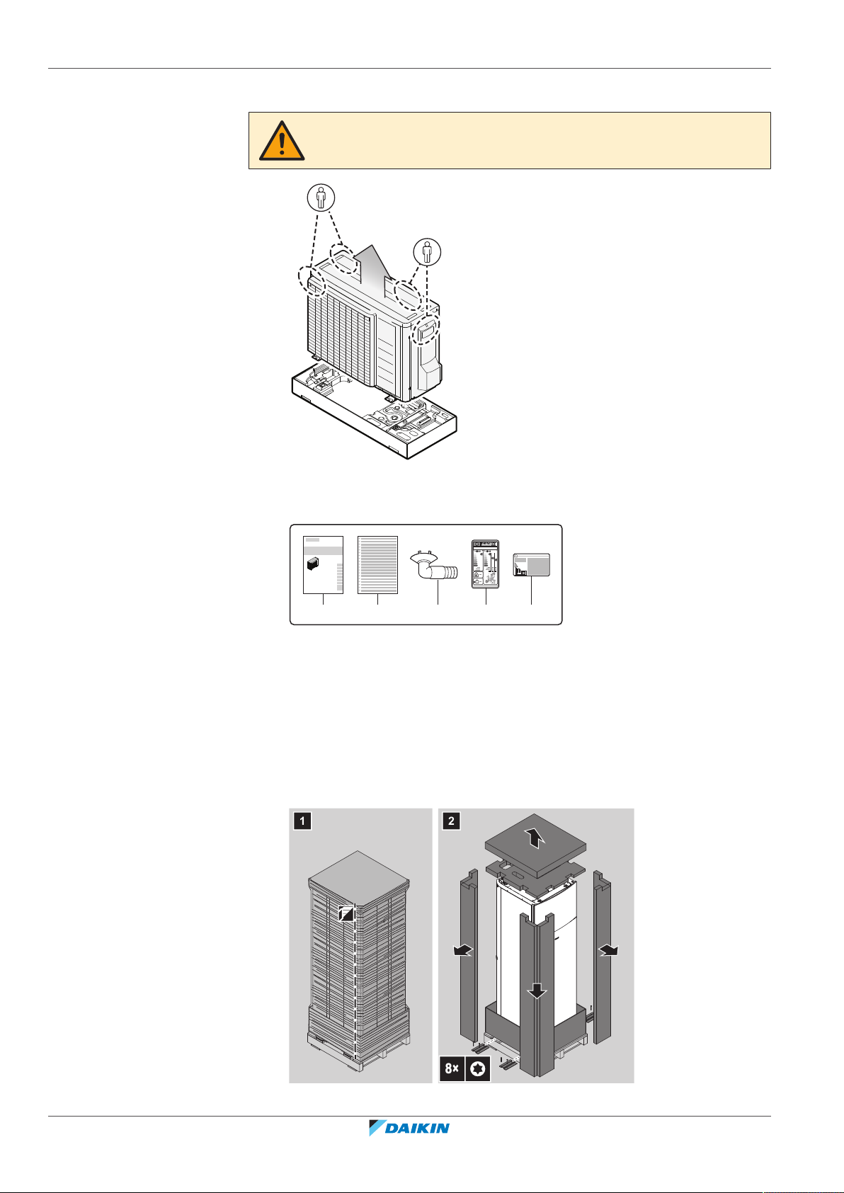
3.3.1 To unpack the indoor unit
Installer reference guide
18
ERLA03DAV3 + EHFZ03S18DJ3V
Daikin Altherma 3 R F
4P596821-1 – 2019.10
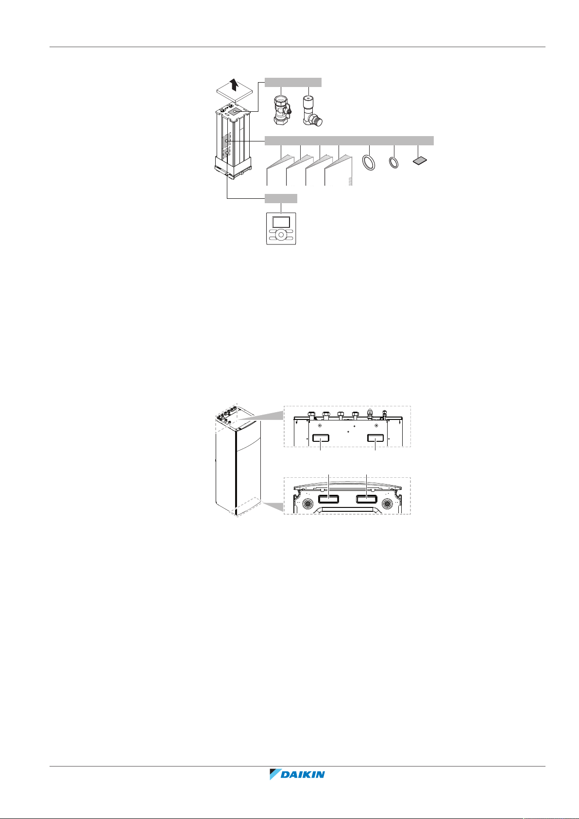
3.3.2 To remove the accessories from the indoor unit
4×
6×1×4× 1×
1× 1× 1× 1×
a b
g h ic d e f
1×
j
b
a a
b
a Shut-off valves for water circuit
b Overpressure bypass valve
c General safety precautions
d Addendum book for optional equipment
e Indoor unit installation manual
f Operation manual
g Sealing rings for shut-off valves (space heating water circuit)
h Sealing rings for field-supplied shut-off valves (domestic hot water circuit)
i Sealing tape for low voltage wiring intake
j Remote user interface
3 | About the box
3.3.3 To handle the indoor unit
Use the handles at the back and at the bottom to carry the unit.
a Handles at the back of the unit
b Handles at the bottom of the unit. Carefully tilt the unit to the back so that the handles become visible.
ERLA03DAV3 + EHFZ03S18DJ3V
Daikin Altherma 3 R F
4P596821-1 – 2019.10
Installer reference guide
19
4 | About the units and options
4 About the units and options
In this chapter
4.1 Overview: About the units and options ................................................................................................................................. 20
4.2 Identification........................................................................................................................................................................... 20
4.2.1 Identification label: Outdoor unit .......................................................................................................................... 20
4.2.2 Identification label: Indoor unit ............................................................................................................................. 21
4.3 Combining units and options.................................................................................................................................................. 21
4.3.1 Possible combinations of indoor unit and outdoor unit ....................................................................................... 21
4.3.2 Possible options for the outdoor unit.................................................................................................................... 21
4.3.3 Possible options for the indoor unit ...................................................................................................................... 22
4.1 Overview: About the units and options
This chapter contains information about:
▪ Identifying the outdoor unit
▪ Identifying the indoor unit
▪ Combining the outdoor unit with options
▪ Combining the indoor unit with options
4.2 Identification
NOTICE
When installing or servicing several units at the same time, make sure NOT to switch
the service panels between different models.
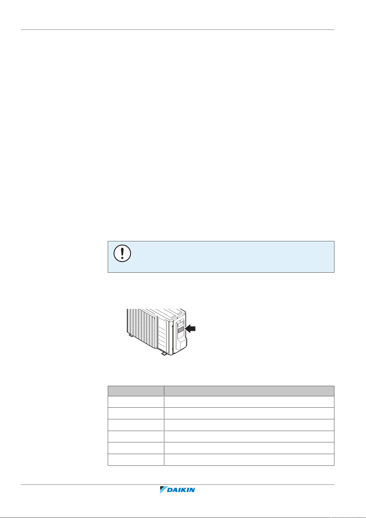
4.2.1 Identification label: Outdoor unit
Location
Model identification
Example: ERLA03DAV3
Installer reference guide
20
Code Explanation
ER European split outdoor pair heat pump
L Low water temperature – ambient zone: −10~−20°C
A Refrigerant R32
03 Capacity class
DA Model series
V3 Power supply
ERLA03DAV3 + EHFZ03S18DJ3V
Daikin Altherma 3 R F
4P596821-1 – 2019.10
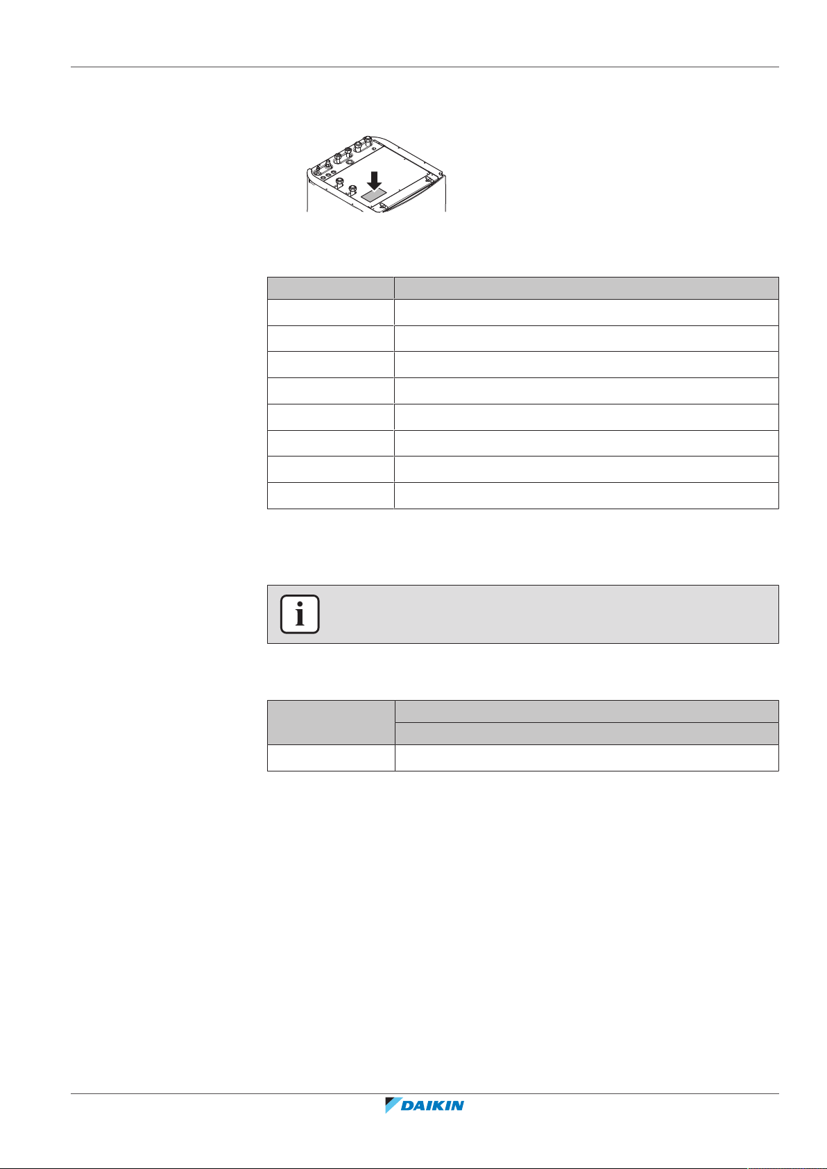
4.2.2 Identification label: Indoor unit
Location
Model identification
Example: EHFZ03S18DJ3V
Code Description
E European model
HF Floor-standing indoor unit with integrated tank
Z Dual-zone model
03 Capacity class
S Integrated tank material: Stainless steel
18 Integrated tank volume
4 | About the units and options
DJ Model series
3V Backup heater model
4.3 Combining units and options
INFORMATION
Certain options might not be available in your country.
4.3.1 Possible combinations of indoor unit and outdoor unit
Outdoor unit Indoor unit
ERLA03DAV3 O
4.3.2 Possible options for the outdoor unit
Bottom plate heater (EKBPHT03D)
▪ Prevents freeze-up of the bottom plate.
EHFZ03S18DJ3V
ERLA03DAV3 + EHFZ03S18DJ3V
Daikin Altherma 3 R F
4P596821-1 – 2019.10
▪ Recommended in areas with low ambient temperature and high humidity.
▪ Required in areas with ambient temperatures between –7°C and –15°C when the
outdoor unit is installed between 1000 m and 2000 m altitude. See
"6.1.2 Additional installation site requirements of the outdoor unit in cold
climates"[440] for more information.
▪ For installation instructions, see the installation manual of the bottom plate
heater.
Installer reference guide
21

4 | About the units and options
4.3.3 Possible options for the indoor unit
User interface used as room thermostat (BRC1HHDA)
▪ The user interface used as room thermostat can only be used in combination
with the user interface connected to the indoor unit.
▪ The user interface used as room thermostat needs to be installed in the room
that you want to control.
For installation instructions, see the installation and operation manual of the user
interface used as room thermostat.
Room thermostat (EKRTWA, EKRTR1)
You can connect an optional room thermostat to the indoor unit. This thermostat
can either be wired (EKRTWA) or wireless (EKRTR1).
For installation instructions, see the installation manual of the room thermostat
and addendum book for optional equipment.
Remote sensor for wireless thermostat (EKRTETS)
You can use a wireless indoor temperature sensor (EKRTETS) only in combination
with the wireless thermostat (EKRTR1).
For installation instructions, see the installation manual of the room thermostat
and addendum book for optional equipment.
Digital I/O PCB (EKRP1HBAA)
The digital I/O PCB is required to provide following signals:
▪ Alarm output
▪ Space heating On/OFF output
▪ Changeover to external heat source
For installation instructions, see the installation manual of the digital I/O PCB and
addendum book for optional equipment.
Demand PCB (EKRP1AHTA)
To enable the power saving consumption control by digital inputs you must install
the demand PCB.
For installation instructions, see the installation manual of the demand PCB and
addendum book for optional equipment.
Remote indoor sensor (KRCS01-1)
By default the internal user interface sensor will be used as room temperature
sensor.
As an option the remote indoor sensor can be installed to measure the room
temperature on another location.
Installer reference guide
22
For installation instructions, see the installation manual of the remote indoor
sensor and addendum book for optional equipment.
INFORMATION
▪ The remote indoor sensor can only be used in case the user interface is
configured with room thermostat functionality.
▪ You can only connect either the remote indoor sensor or the remote outdoor
sensor.
ERLA03DAV3 + EHFZ03S18DJ3V
Daikin Altherma 3 R F
4P596821-1 – 2019.10

4 | About the units and options
Remote outdoor sensor (EKRSCA1)
By default the sensor inside the outdoor unit will be used to measure the outdoor
temperature.
As an option the remote outdoor sensor can be installed to measure the outdoor
temperature on another location (e.g. to avoid direct sunlight) to have an
improved system behaviour.
For installation instructions, see the installation manual of the remote outdoor
sensor and the addendum book for optional equipment.
INFORMATION
You can only connect either the remote indoor sensor or the remote outdoor sensor.
PC cable (EKPCCAB4)
The PC cable makes a connection between the switch box of the indoor unit and a
PC. It gives the possibility to update the software of the indoor unit.
For installation instructions, see the installation manual of the PC cable.
Pipe bend kit (EKHVTC)
When the indoor unit is installed in a place with limited space, a pipe bend kit can
be installed to facilitate the connection to the refrigerant liquid and gas
connections of the indoor unit.
For installation instructions, see the instruction sheet of the pipe bend kit.
Heat pump convector (FWXV)
For installation instructions, see the installation manual of the heat pump
convectors, and the addendum book for optional equipment.
LAN adapter for smartphone control + Smart Grid applications (BRP069A61)
You can install this LAN adapter to:
▪ Control the system via a smartphone app.
▪ Use the system in various Smart Grid applications.
For installation instructions, see the installation manual of the LAN adapter.
LAN adapter for smartphone control (BRP069A62)
You can install this LAN adapter to control the system via a smartphone app.
For installation instructions, see the installation manual of the LAN adapter.
ERLA03DAV3 + EHFZ03S18DJ3V
Daikin Altherma 3 R F
4P596821-1 – 2019.10
Installer reference guide
23
5 | Application guidelines
5 Application guidelines
In this chapter
5.1 Overview: Application guidelines........................................................................................................................................... 24
5.2 Setting up the space heating system ..................................................................................................................................... 24
5.2.1 Multiple rooms – TwoLWT zones ......................................................................................................................... 25
5.3 Setting up the domestic hot water tank ................................................................................................................................ 27
5.3.1 System layout – Integrated DHW tank .................................................................................................................. 27
5.3.2 Selecting the desired temperature for the DHW tank .......................................................................................... 27
5.3.3 Setup and configuration – DHW tank .................................................................................................................... 28
5.3.4 DHW pump for instant hot water .......................................................................................................................... 29
5.3.5 DHW pump for disinfection ................................................................................................................................... 29
5.4 Setting up the energy metering ............................................................................................................................................. 30
5.4.1 Produced heat ........................................................................................................................................................ 30
5.4.2 Consumed energy .................................................................................................................................................. 30
5.4.3 Normal kWh rate power supply............................................................................................................................. 31
5.4.4 Preferential kWh rate power supply...................................................................................................................... 32
5.5 Setting up the power consumption control........................................................................................................................... 33
5.5.1 Permanent power limitation.................................................................................................................................. 33
5.5.2 Power limitation activated by digital inputs .......................................................................................................... 34
5.5.3 Power limitation process ....................................................................................................................................... 35
5.6 Setting up an external temperature sensor........................................................................................................................... 35
5.1 Overview: Application guidelines
The purpose of the application guidelines is to give a glance of the possibilities of
the heatpump system.
NOTICE
▪ The illustrations in the application guidelines are meant for reference only, and
are NOT to be used as detailed hydraulic diagrams. The detailed hydraulic
dimensioning and balancing are NOT shown, and are the responsibility of the
installer.
▪ For more information about the configuration settings to optimize heat pump
operation, see "9Configuration"[498].
This chapter contains application guidelines for:
▪ Setting up the space heating system
▪ Setting up the domestic hot water tank
▪ Setting up the energy metering
▪ Setting up the power consumption control
▪ Setting up an external temperature sensor
5.2 Setting up the space heating system
Installer reference guide
24
The heat pump system supplies leaving water to heat emitters in one or more
rooms.
Because the system offers a wide flexibility to control the temperature in each
room, you need to answer the following questions first:
▪ How many rooms are heated by the heatpump system?
▪ Which heat emitter types are used in each room and what is their design leaving
water temperature?
ERLA03DAV3 + EHFZ03S18DJ3V
Daikin Altherma 3 R F
4P596821-1 – 2019.10
Once the space heating requirements are clear, we recommend to follow the setup
B
A
D
E
C
b
a a
guidelines below.
NOTICE
If an external room thermostat is used, the external room thermostat will control the
room frost protection. However, the room frost protection is only possible if the
leaving water temperature control on user interface of the unit is turned ON.
INFORMATION
In case an external room thermostat is used and room frost protection needs to be
guaranteed in all conditions, then you have to set auto emergency [A.6.C] to 1.
NOTICE
An overpressure bypass valve can be integrated in the system. Keep in mind that this
valve might not be shown on the illustrations.
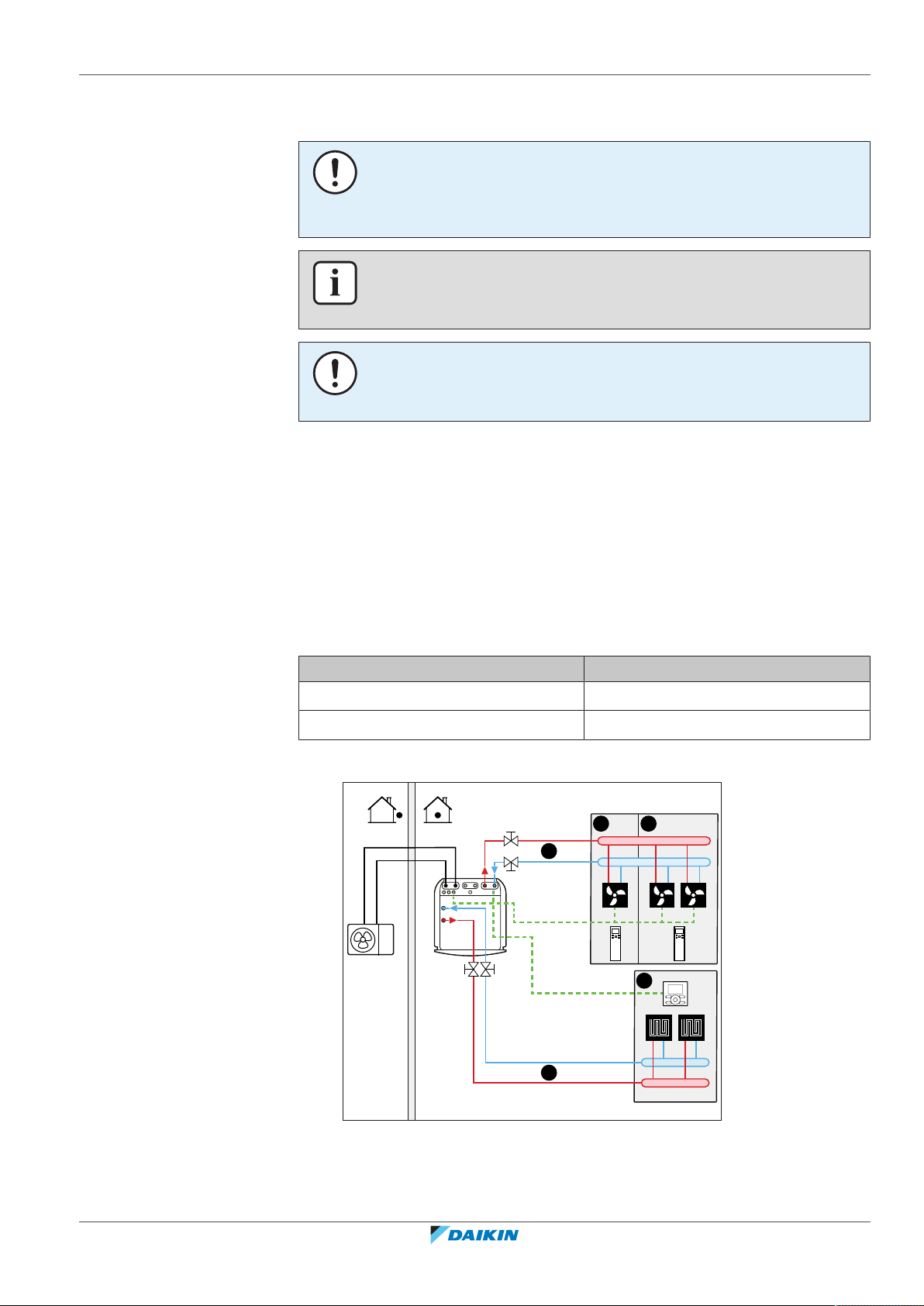
5.2.1 Multiple rooms – TwoLWT zones
This unit is designed to deliver water at 2 different temperatures. A typical
installation consists of underfloor heating at a lower temperature and radiators at
a higher water temperature.
5 | Application guidelines
In this document:
▪ Main zone = Zone with the lowest design temperature
▪ Additional zone = Zone with the highest design temperature
Typical example:
Room (zone) Heat emitters: Design temperature
Living room (main zone) Underfloor heating: 35°C
Bed rooms (additional zone) Heat pump convectors: 45°C
Setup
ERLA03DAV3 + EHFZ03S18DJ3V
Daikin Altherma 3 R F
4P596821-1 – 2019.10
A Additional leaving water temperature zone
B Room 1
C Room 2
D Main leaving water temperature zone
E Room 3
a Remote controller of the heat pump convectors
Installer reference guide
25

5 | Application guidelines
b User interface used as room thermostat
▪ For the main zone: the room temperature is controlled by the user interface,
which is used as room thermostat (optional equipment EKRUDAS).
▪ For the additional zone:
- The external thermostat is directly connected to the indoor unit.
- The desired room temperature is set via the external thermostat and the
thermostatic valves of the radiators in each room.
- The heating demand signal from the external thermostat is connected to the
digital input on the indoor unit (X2M/35a and X2M/30). The indoor unit will
only supply the desired additional leaving water temperature when there is an
actual demand.
▪ The user interface connected to the indoor unit decides the space operation
mode. Mind that the operation mode on each remote controller of the
heatpump convectors must be set to match the indoor unit.
Configuration
Setting Value
Unit temperature control:
▪ #: [A.2.1.7]
2 (RT control): Unit operation is
decided based on the ambient
temperature of the user interface.
▪ Code: [C-07]
Note:
▪ Main room = user interface used as
room thermostat functionality
▪ Other rooms = external room
thermostat functionality
Number of water temperature zones:
1 (2 LWT zones): Main + additional
▪ #: [A.8]
▪ Code: [7-02]
In case of heatpump convectors:
External room thermostat for the
additional zone:
1 (Thermo ON/OFF): When the used
external room thermostat or heatpump
convector can only send a hermos ON/
OFF condition. No separation between
▪ #: [A.8]
heating or cooling demand.
▪ Code: [C-06]
Shut-off valve output Set to follow the hermos demand of the
main zone.
Installer reference guide
26
Benefits
▪ Comfort. The smart room thermostat functionality can decrease or increase the
desired leaving water temperature based on the actual room temperature
(modulation).
▪ Efficiency.
- Depending on the demand, the indoor unit supplies different leaving water
temperature matching the design temperature of the different heat emitters.
- Underfloor heating has the best performance with the heat pump system.
ERLA03DAV3 + EHFZ03S18DJ3V
Daikin Altherma 3 R F
4P596821-1 – 2019.10
5.3 Setting up the domestic hot water tank
A
a
b
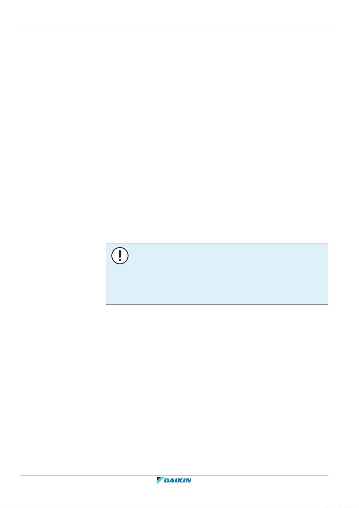
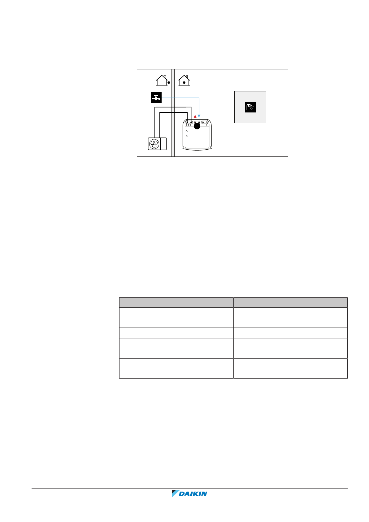
5.3.1 System layout – Integrated DHW tank
A Domestic hot water
a Cold water IN
b Hot water OUT
5.3.2 Selecting the desired temperature for the DHW tank
5 | Application guidelines
People experience water as hot when its temperature is 40°C. Therefore, the DHW
consumption is always expressed as equivalent hot water volume at 40°C.
However, you can set the DHW tank temperature at a higher temperature
(example: 53°C), which is then mixed with cold water (example: 15°C).
Selecting the desired temperature for the DHW tank consists of:
1 Determining the DHW consumption (equivalent hot water volume at 40°C).
2 Determining the desired temperature for the DHW tank.
Determining the DHW consumption
Answer the following questions and calculate the DHW consumption (equivalent
hot water volume at 40°C) using typical water volumes:
Question Typical water volume
How many showers are needed per
1shower = 10min×10l/min = 100l
day?
How many baths are needed per day? 1bath = 150l
How much water is needed at the
1sink = 2min×5l/min = 10l
kitchen sink per day?
Are there any other domestic hot water
—
needs?
Example: If the DHW consumption for 2 persons per day is as follows:
▪ 1 showers
▪ 1 bath
▪ 2 sink volumes
Then the DHW consumption = (1×100l)+(1×150l)+(2×10l)=270l
ERLA03DAV3 + EHFZ03S18DJ3V
Daikin Altherma 3 R F
4P596821-1 – 2019.10
Installer reference guide
27

5 | Application guidelines
Determining the desired temperature for the DHW tank
Formula Example
V1=V2+V2×(T2−40)/(40−T1) If:
▪ V2=180l
▪ T2=54°C
▪ T1=15°C
Then V1=280l
V1DHW consumption (equivalent hot water volume at 40°C)
V2Required DHW tank volume if only heated once
T2DHW tank temperature
T1Cold water temperature
DHW tank volume
Integrated DHW tank volume: 180l (=V2)
Energy saving tips
▪ If the DHW consumption differs from day to day, you can program a weekly
schedule with different desired DHW tank temperatures for each day.
▪ The lower the desired DHW tank temperature, the more cost effective. By
selecting a larger DHW tank, you can lower the desired DHW tank temperature.
▪ The heatpump itself can produce domestic hot water of maximum 55°C (50°C if
outdoor temperature is low). The electrical resistance integrated in the
heatpump can increase this temperature. However, this consumes more energy.
We recommend to set the desired DHW tank temperature below 55°C to avoid
using the backup heater.
▪ The higher the outdoor temperature, the better the performance of the
heatpump.
- If energy prices are the same during the day and the night, we recommend to
heat up the DHW tank during the day.
- If energy prices are lower during the night, we recommend to heat up the DHW
tank during the night.
▪ When the heatpump produces domestic hot water, it cannot heat up a space. In
case you need domestic hot water and space heating at the same, we
recommend to produce the domestic hot water during the night when there is
lower space heating demand.
5.3.3 Setup and configuration – DHW tank
Installer reference guide
28
▪ For large DHW consumptions, you can heat up the DHW tank several times
during the day.
▪ To heat up the DHW tank to the desired DHW tank temperature, you can use the
following energy sources:
- Thermodynamic cycle of the heatpump
- Electrical backup heater
▪ For more information about optimizing the energy consumption for producing
domestic hot water, see "9Configuration"[498].
ERLA03DAV3 + EHFZ03S18DJ3V
Daikin Altherma 3 R F
4P596821-1 – 2019.10
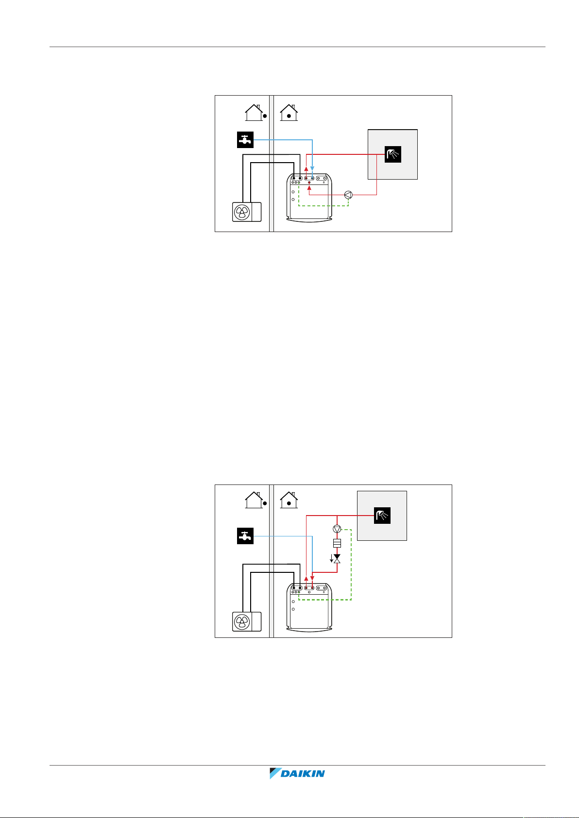
5.3.4 DHW pump for instant hot water
a
b
c
d
a
b
c
d
e
Setup
a Cold water IN
b Hot water OUT (shower (field supply))
c DHW pump (field supply)
d Recirculation connection
▪ By connecting a DHW pump, instant hot water can be available at the tap.
▪ The DHW pump and the installation are field supply and the responsibility of the
installer. For the electrical wiring, see "8.3.6To connect the domestic hot water
pump"[489].
5 | Application guidelines
For more information about connecting the recirculation connection, see "7.6.4To
connect the recirculation piping"[473].
Configuration
▪ For more information, see "9Configuration"[498].
▪ You can program a schedule to control the DHW pump via the user interface. For
more information, see the user reference guide.
5.3.5 DHW pump for disinfection
Setup
a Cold water IN
b Hot water OUT (shower (field supply))
c DHW pump (field supply)
d Heater element (field supply)
e Non-return valve (field supply)
ERLA03DAV3 + EHFZ03S18DJ3V
Daikin Altherma 3 R F
4P596821-1 – 2019.10
▪ The DHW pump is field-supplied and its installation is the responsibility of the
installer. For the electrical wiring, see "8.3.6To connect the domestic hot water
pump"[489].
Installer reference guide
29
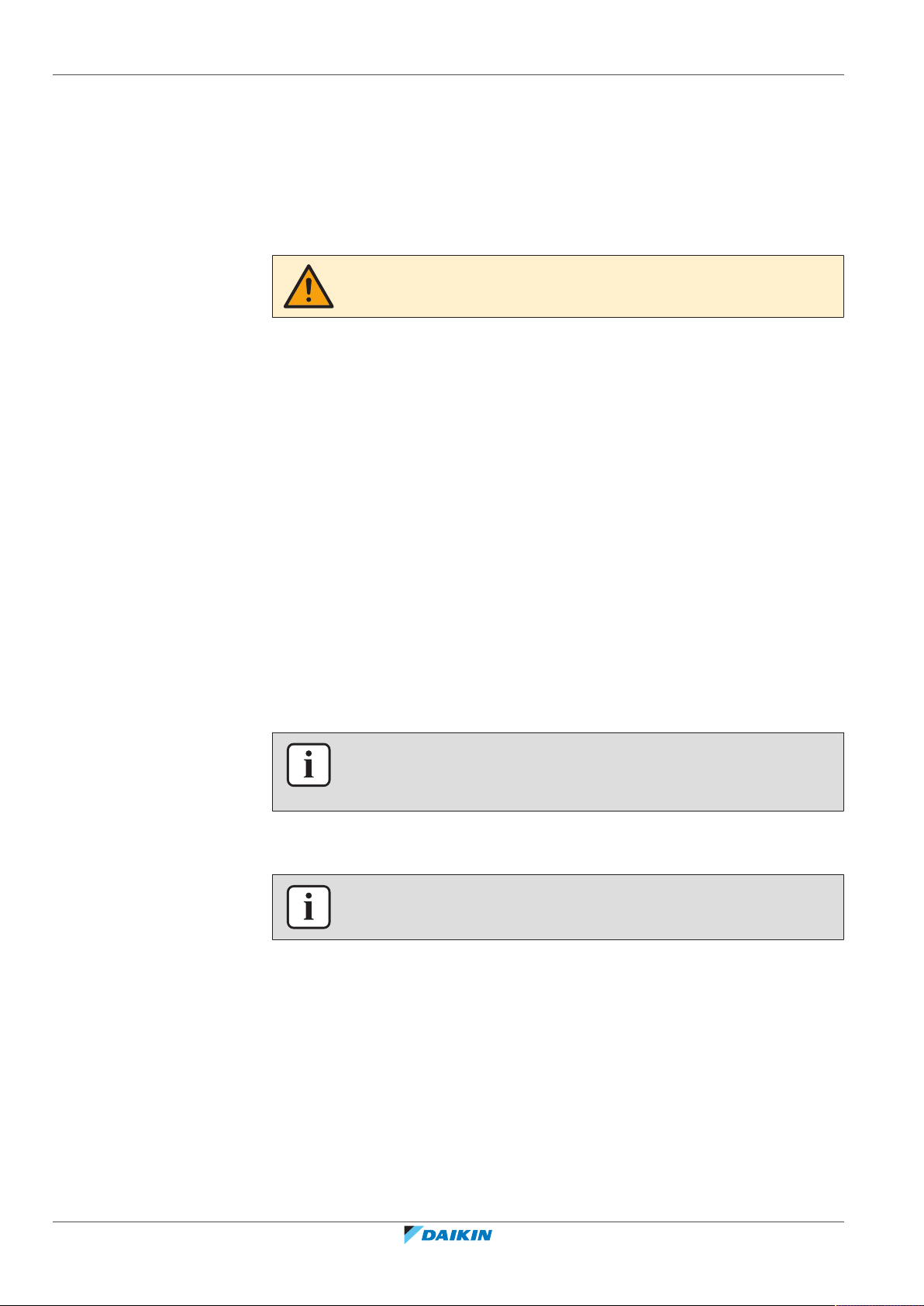
5 | Application guidelines
5.4 Setting up the energy metering
▪ If the applicable legislation requires a higher temperature than the maximum
tank setpoint during disinfection (see [2-03] in the field settings table), you can
connect a DHW pump and heater element as shown above.
▪ If applicable legislation requires disinfection of the water piping until the tapping
point, you can connect a DHW pump and heater element (if needed) as shown
above.
▪ To ensure a complete disinfection, you have to open the tapping point.
WARNING
When opening the tapping point, the water temperature can be up to 55°C.
Configuration
The indoor unit can control DHW pump operation. For more information, see
"9Configuration"[498].
▪ Via the user interface, you can read out the following energy data:
5.4.1 Produced heat
- Produced heat
- Consumed energy
▪ You can read out the energy data:
- For space heating
- For domestic hot water production
▪ You can read out the energy data:
- Per month
- Per year
INFORMATION
The calculated produced heat and consumed energy are an estimation, the accuracy
cannot be guaranteed.
INFORMATION
The sensors used to calculate the produced heat are calibrated automatically.
▪ The produced heat is calculated internally based on:
5.4.2 Consumed energy
Installer reference guide
30
- The leaving and entering water temperature
- The flow rate
▪ Setup and configuration: No additional equipment needed.
You can use the following methods to determine the consumed energy:
▪ Calculating
▪ Measuring
ERLA03DAV3 + EHFZ03S18DJ3V
Daikin Altherma 3 R F
4P596821-1 – 2019.10
 Loading...