

Page 1

ECFWEB6
ECFWER6
ECFWDER6
INSTALLATION AND
OPERATION MANUAL
Microprocessor controller for fan coils
Page 2

2
3
2
5
1
3 4 5 6 7 8 9
34 5 6 789
2
3
16.5°C 28.5°C
22.5°C
5
3
4
12
2
6 7 8
22
11
91011 12
130
86
9.3
7
19
24
93
4 5
7 86
22
11
105
90
7
0
22
11
2 x (ø5x8)
17.7
7
109
11
12
Page 3
13 16
13 16
14
14 17
15
19
17
19
20
18
15 18
20
21
4
2
21
Page 4

ECFWEB6
ECFWER6
ECFWDER6
T
ABLE OF CONTENTS
Main features .................................................................1
Main functions and equipment....................................... 1
Packing list.............................................................. 2
Control panel ..........................................................2
Temperature range .................................................2
LED indicators ........................................................2
Description of the operating modes........................ 3
Technical data and operation limits ........................5
Possible configurations.................................................. 7
Before installation ..........................................................9
ECFWEB6 installation instructions ................................9
Installation on the support and on the fan coil........9
ECFWER6 + ECFWDER6 installation instructions...... 10
Installation ............................................................10
Setting the microswitches ............................................10
Installing the air and water temperature probes...........11
Position of the air temperature probe ...................11
Position of the water temperature probe...............11
Installing the power contactor ......................................12
Wiring diagrams...........................................................12
Wiring parts table .................................................12
Read this manual attentively before starting up
the unit. Do not throw it away. Keep it in your
files for future reference.
Improper installation or attachment of
equipment or accessories could result in
electric chock, short-circuit, leaks, fire or other
damage to the equipment. Be sure only to use
accessories made by Daikin which are
specifically designed for the use with the
equipment and have them installed by a
professional.
If unsure of installation procedures or use,
always contact your Daikin dealer for advice
and information.
Microprocessor controller
for fan coils
Page
Installation and
operation manual
If options need to be installed, always refer to
the relevant manual of the option for additional
information.
M
AIN FEATURES
This controller is designed to control Daikin fan coil units.
■
ECFWEB6 Built-in for FWV and FWL
■
ECFWER6 Remote for FWV, FWL and FWM
■
ECFWDER6 Remote for FWD
M
AIN FUNCTIONS AND EQUIPMENT
■
Regulation of the air temperature via automatic
variation of the fan speed.
■
Regulation of the air temperature via ON/OFF switch
of the fan at a fixed speed.
■
Time function (only for ECFWEB6).
■
Regulation of the air temperature via control of ON/OFF
valves (on 2-pipe or 4-pipe systems).
■
Control of the electric heater as integration or
replacement of a heating circuit with delayed fan
stopping.
■
Cooling/Heating switching mode in following way:
■
Manual — on the controller
■
Manual — on the remote switch
■
Automatic — based on the water temperature
■
Automatic — based on the air temperature
■
The controller is also equipped with:
■
Free contacts for external enabling signal (i.e.:
reed contact, remote ON/OFF switch, proximity
contact etc.) that may enable or disable the unit.
(Closed contact = OFF; open contact= ON)
■
Free contacts for the centralized cooling/heating
switching system. (Closed contact = cooling,
open contact = heating)
■
Water temperature probe (white)
■
Air temperature probe (black)
Installation and operation manual
1
4PW17551-1
ECFWEB6+ECFWER6+ECFWDER6
Microprocessor controller for fan coils
Page 5
Part
(See figure 1)
ECFWEB6 ECFWER6 ECFWDER6
111
integrated in controller
Packing list
1
Controller 1 1 1
2
Manual 1 1 1
3
Cover plate left 1 0 0
4
Cover plate right 1 0 0
5
Support 1 0 0
6
Accessory bag
•wire clamp
•2 screws
•probe holder
7
Water probe 1 1 1
8
Air probe 1
9
Power interface 0 0 1
Control panel
Refer to figure 2 to catch the look of the controller.
1
Operation mode selector, to turn the fan coil on
and off, to choose the type of operating mode
(automatic or at fixed speed) and to control the
electric heating.
2
Operation LED indicating that cooling operation
mode is active (blue).
3
Cooling/Heating selector.
4
Operation LED indicating that heating operation
mode is active (red).
5
Thermostat to control the room temperature.
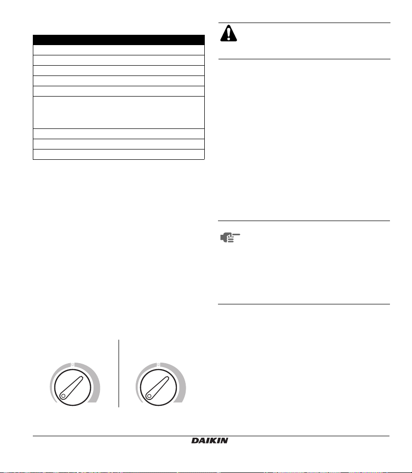
Temperature range
The print around the selector switch of the thermostat
represents temperature ranges from minimum, over
comfort, to maximum. The ranges refer to different
temperatures, depending on the selected operating
mode as illustrated in the figure below.
Cooling mode Heating mode
25°C
19°C31°C
20°C
14°C26°C
When automatic cooling/heating switching
mode based on the air temperature is running,
the temperature of the thermostat is as
illustrated in figure 3.
LED indicators
The various combinations in which the LED lights up
indicate procedures and operating status of the
controller.
■
Blue LED lit
running. The unit is running or waiting for an input
from the thermostat.
■
Red LED lit
running. The unit is running or waiting for an input
from the thermostat.
■
Blue and red LEDs lit
receive an enabling signal. The water temperature
does not enable the air cooling or heating functions
(see "Automatic cooling/heating switching mode
based on the water temperature" on page 3) or the
temperature of the air is within the neutral zone (see
"Automatic cooling/heating switching mode based on
the air temperature" on page 4).
NOTE
■
Double flashing of the blue LED
thermostat has sent an input to the unit for starting
cooling mode. It flashes when the room temperature
and the set cooling temperature are the same.
■
Double flashing of the red LED
thermostat has sent an input to the unit for starting
heating mode. It flashes when the room temperature
and the set heating temperature are the same.
The temperature of the air in the room can be seen at
any time on the thermostat range turning the knob of the
thermostat.
indicates that the cooling mode is
indicates that the heating mode is
indicates that the unit did not
To determine which operating mode is
selected when an enabling signal is
missing (blue and red LEDs are both lit),
turn the knob of the thermostat until one of
the two LEDs starts to flash and then
remains lit. This LED points out the
selected operating mode. Once the
operating mode has been established, turn
the thermostat back to the desired
position.
means that the
means that the
ECFWEB6+ECFWER6+ECFWDER6
Microprocessor controller for fan coils
4PW17551-1
Installation and operation manual
2
Page 6

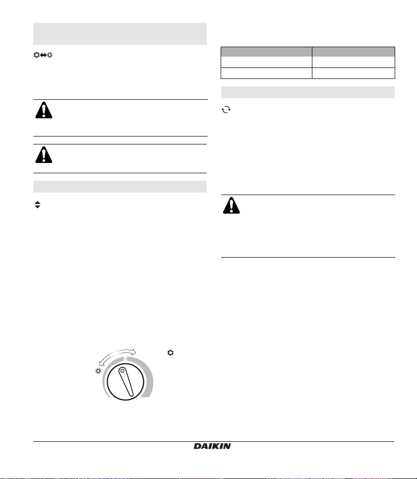
Description of the operating modes
D
O
Room thermostat with air temperature control
With the speed selector switch turned to , the fan
speed is switched automatically based on the difference
between the temperature set on the thermostat and the
room temperature.
With the selector switch turned to , , or the
ventilation mode is of the ON/OFF type.
Room thermostat with ON/OFF valve control for
2-pipe systems
With the speed selector switch turned to , the fan
speed is switched automatically based on the difference
between the temperature set on the thermostat and the
room temperature.
With the selector switch turned to , , or the
ventilation mode is of the ON/OFF type.
The water valve is shut off once the desired temperature
is reached
In cooling mode the fan continues at minimum speed,
even after the valve of the cooling circuit has shut off.
In heating mode the fan is stopped as soon as the valve
of the heating circuit is shut off.
Room thermostat with ON/OFF valve control for
4-pipe systems
Manual built-in cooling/heating switching mode
M
The controller is pre-arranged to operate manually in the
desired mode. It is enabled by pressing the selector key.
The blue (cooling) and red (heating) LEDs point out the
selected operating mode.
Manual remote cooling/heating switching mode
M
The controller is pre-arranged to operate manually and
remotely in the desired mode. This mode is carried out
by connecting the system to a remote switch. Use the
special terminals on the electronic PCB of the controller.
Automatic cooling/heating switching mode
based on the water temperature
H
2
The controller automatically selects the cooling or
heating mode based on the temperature of the water and
according to the following logic:
Water temperature <17°C — cooling mode is set
Water temperature >37°C — heating mode is set
Water temperature between 17°C and 37°C — the
system is disabled
For switching based on water temperature, the
supplied water probe needs to be installed.
See chapter "Position of the water temperature
probe" on page 11 for installation of the water
temperature probe.
With the speed selector switch turned to , the fan
speed is switched automatically based on the difference
between the temperature set on the thermostat and the
room temperature.
With the selector switch turned to , , or the
ventilation mode is of the ON/OFF type.
The water valve is shut off once the desired temperature
is reached
In cooling mode the fan continues at minimum speed
even after the valve of the cooling circuit has shut off.
In heating mode the fan is stopped as soon the valve of
the heating circuit is shut off.
Installation and operation manual
3
4PW17551-1
In this type of configuration, the input for the
centralised cooling/heating switching mode is
disabled.
ECFWEB6+ECFWER6+ECFWDER6
Microprocessor controller for fan coils
Page 7
Automatic cooling/heating switching mode
R
21
based on the air temperature
AI
The controller selects the cooling or heating mode based
on the temperature of the air compared to a neutral
temperature interval (neutral zone) centred on the set
value of the thermostat.
When this function is selected, the
temperature range of the thermostat refers to
the values indicated in figure 3, both for
cooling and for heating.
In this type of configuration, the input for the
centralised cooling/heating switching mode is
disabled.
Selecting the range of the neutral zone
The neutral zone is a parameter related to the function
"automatic cooling/heating switching mode based on the
air temperature".
The neutral zone is a temperature interval astride the set
temperature. When the air is warmer than the top limit of
the neutral zone, the cooling mode is selected.
When the air is cooler than the lower limit of the neutral
zone, the heating mode is selected.
The following figure illustrates an example with:
Neutral zone = 5°C
Set room air temperature = 21°C
For temperatures above 23.5°C the cooling operating
mode is selected
For temperatures below 18.5°C the heating operating
mode is selected.
Neutral zone
<18.5°C =
>23.5°C =
21
°C21°C
On the controller, the range of the neutral zone is 2°C or
5°C and can be defined by setting microswitch number 4
(see "Setting the microswitches" on page 10).
Position of microswitch no. 4
Range of the neutral zone
ON 2°C
OFF 5°C
Time function
The time function is used to start the fan at medium
speed for 2 minutes at regular intervals (every 10
minutes) once the room temperature has reached the
level as set on the thermostat. It ensures the constant
monitoring of the air temperature in the room. It is only
used in summer and only if the enabling signal of the
water temperature probe is positive.
The time function cycle is also executed when the
controller is powered (first start-up or voltage reset).
The thermostat and the operating mode
selector switch are disabled when the time
function is in use.
The time function can be used only for units
without valves and only in summer.
The time function is not foreseen for the
ECFWER6 and ECFWDER6 versions.
ECFWEB6+ECFWER6+ECFWDER6
Microprocessor controller for fan coils
4PW17551-1
Installation and operation manual
4
Page 8
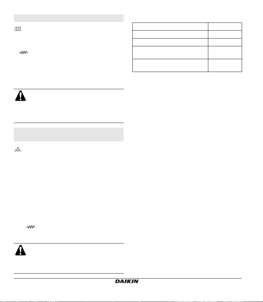
Electric heater control
The thermostat controls an electric heater as integration
or replacement of a hot water heating system.
When the operating mode selector switch is turned
to and the electric heater is turned on, the fan runs
continuously at medium speed.
For safety reasons, the fan is turned off 2 minutes after
the electric heater is turned off, whether this occurs
when the desired air temperature is reached or when the
electric heater is turned off manually using the operating
mode selector.
■
During operation of the electric heater, the
fan runs at medium speed only.
■
During heating operation of 2-pipe system
units equipped with an electric heater and
motorised valves, only the electric heater
works.
Fan coil enabling system based on the water
temperature
The controller starts the unit according to the following
logic based on the water temperature that is detected by
a dedicated probe:
■
Water temperature <17°C: Cooling mode enabling
signal
■
Water temperature >37°C: Heating mode enabling
signal
In installations with electric heater control, the same
probe sends the enabling signal for the electric heater to
turn on according to the following logic:
■
Water temperature <37°C: Additional electric heater
enabling signal. (This enabling signal is sent only if
the operating mode selector switch is turned
to ).
■
Water temperature >39°C: The additional electric
heater is switched off.
For switching based on water temperature, the
supplied water probe needs to be installed.
See "Position of the water temperature probe"
on page 11 for installation of the water
temperature probe.
Technical data and operation limits
Warehouse temperatures –40°C~85°C
Operation temperatures 0°C~40°C
Accuracy of temperature probes ±0.5°C
Maximum current on terminal V1, V2
and V3 (fan speed)
Maximum current on terminal R and
V (valve and electric heater)
1.1 A
0.15 A
Installation and operation manual
5
4PW17551-1
ECFWEB6+ECFWER6+ECFWDER6
Microprocessor controller for fan coils
Page 9

NOTES
ECFWEB6+ECFWER6+ECFWDER6
Microprocessor controller for fan coils
4PW17551-1
Installation and operation manual
6
Page 10

P
D
O
R
OSSIBLE CONFIGURATIONS
In this chapter we describe all possible configurations
(C1➞C18) for controlling the unit.
Select the configuration that best complies to the system
characteristics. Possible functions are combined in
various configurations and are defined by setting the
microswitches on the electronic PCB accordingly. Refer
to "Installation on the support and on the fan coil" on
page 9 and to "Setting the microswitches" on page 10.
To find the relation of the system characteristics with the
correct wiring diagram and the correct setting of the
microswitches to be used in function of the desired
control, combine the table on page 8 with the table at the
very end of this manual.
This table lists the following items for all possible
configurations:
■
activated functions
Room thermostat with air
temperature control
Room thermostat with ON-OFF
valve for 2-pipe systems
Room thermostat with ON-OFF
valve for 4-pipe systems
M
M
H
2
AI
Manual built-in cooling/heating
switching mode
Manual remote cooling/heating
switching mode
Automatic cooling/heating switching
mode based on the water
temperature
Automatic cooling/heating switching
mode based on the air temperature
Choice of the range of the neutral
zone
Operational enabling signal based
on the water temperature
Time function (not available for
ECFWER6 + ECFWDER6)
Electric heater control
■
system characteristics
Number of pipes (2 or 4)
Valve (✔ = present, — not present)
Electric heater (✔ = present, — not
present)
■
position of the microswitches
■
corresponding controllers
■
relevant reference to dedicated wiring diagram
()
■
other conventions for complete understanding of the
table:
with a number of units in parallel
1~ 1 phase
3~ 3 phase
Installation and operation manual
7
4PW17551-1
ECFWEB6+ECFWER6+ECFWDER6
Microprocessor controller for fan coils
Page 11

Characteristics List of functions activated
O
C1
Standard two pipe system
C2
Tw o pipe system – Remote switching mode
C3
Tw o pipe system – One valve
C4
Tw o pipe system – One valve – Remote switching mode
C5
Four pipe system – Two valves
C6
Four pipe system – Two valves – Remote switching mode
C7
Four pipe system
C8
Four pipe system – Remote switching mode
C9
Tw o pipe system – Electric heater
C10
Tw o pipe system – Electric heater – Remote switching mode
C11
Tw o pipe system – One valve – Electric heater
C12
Tw o pipe system – One valve – Electric heater – Remote
switching mode
C13
Tw o pipe systems – Automatic switching on water side
C14
Tw o pipe systems – One valve – Automatic switching mode on
water side
C15
Four pipe systems – Automatic switching on air side
C16
Four pipe systems – Two valves – Automatic switching on air
(b)(c)
side
C17
Tw o pipe systems – Electric heater – Automatic switching mode
on air side
C18
Tw o pipe systems – One valve – Electric heater – Automatic
switching mode on air side
(a) Electric heater control: during heating operation only the electric heater works
(b) In this type of configuration, the input for the centralised cooling/heating switching mode is disabled.
(c) For configurations with automatic cooling/heating switching mode based on the air temperature in cooling mode, the fan stops
when the valve shuts off. The enabling signal refers to heating mode only (the water probe is placed on the hot water branch.)
Cooling mode (fan) is always enabled apart from the water temperature (there is only one water temperature probe that is used
to avoid the fan from running with cold water inside the heat exchanger).
(a)
(b)
(b)
(a)(b)
(a)
(b)
(b)
M
MD
M
MD
M
MD
M
MD
M
MD
M
MD
H2O
H
2
AIR
AIR
AIR
AIR
ECFWEB6+ECFWER6+ECFWDER6
Microprocessor controller for fan coils
4PW17551-1
Installation and operation manual
8
Page 12

BEFORE INSTALLATION
■ All field wiring and components must be
installed by a licensed electrician and must
comply with relevant local and national
regulations.
■ Before obtaining access to terminals, all
power circuits must be interrupted.
ECFWEB6 INSTALLATION INSTRUCTIONS
Built-in type controller
The controller has been specially designed for
FWV and FWL units; if used to control other
units, make sure its operation limits are
respected.
Installation on the support and on the fan coil
It is advisable to set the microswitches before installing
the controller, see paragraph "Setting the microswitches"
on page 10.
The controller can be installed on both sides of the unit
using a support and a cover plate.
Proceed as follows to install the controller.
1 Unscrew the four screws hidden behind the hatches
at the end of the grid and remove the fan coil cabinet
(See figure 6).
2 Remove the blank plastic tabs from one of the two
slots of the support to be able to reach the "fast-on's"
of the controller (see figure 4). (The supplied cables
with fast-on's will need to pass through one of the
slots of the support, depending on whether the
controller is to be installed on the right hand or left
hand side of the unit).
1 Support
2 Blank tabs
3 Feed the cables of the probes if any, in one of the
slots of the support and secure the support and
controller together using the two screws supplied.
(See figure 10, it illustrates the installation of the
support and controller when the controller is to be
installed on the right hand side of the unit. If the
controller is to be installed on the left hand side of the
unit, the support is to be turned by 180° compared to
the drawing).
Ensure that all terminals required for the
electrical connections foreseen in the
configuration chosen (valve, electric heater,
external contacts, ...) can be accessed, even
after the support has been installed (see the
correct wiring diagram). If this is not the case,
remove the protective blank tabs from the
base of the support first.
4 Complete all electrical connections according to the
wiring diagrams.
5 Once the electrical connections have been
completed, it is advisable to execute the
autodiagnosis procedure to verify functioning of all
outputs before you finish installation of the controller
(outputs of the fan at various speeds, of the valves
and electric heaters if installed): Refer to the
paragraph "Installing the air and water temperature
probes" on page 11.
6 Assemble the controller-support unit on the fan coil
using the bayonet fittings (see figure 11).
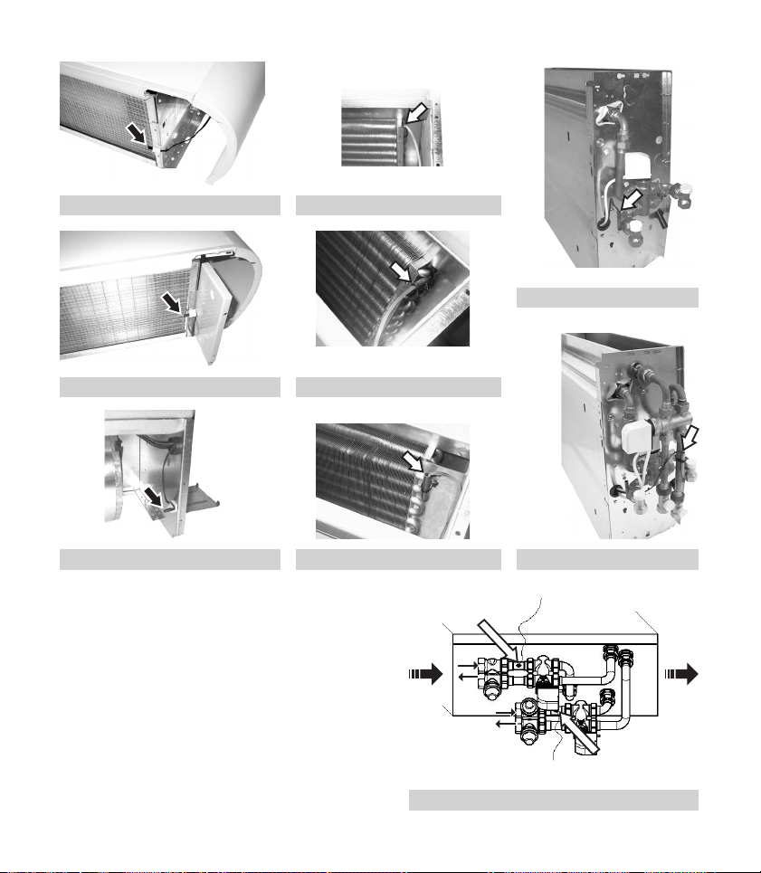
7 Install the air temperature probe (black) and water
temperature probe (white) (see figures 13 unto 20)
following the instructions given in the paragraph
"Installing the air and water temperature probes" on
page 11.
8 Fit the cabinet back in place fix it with the four screws
and then insert the correct cover plate, as illustrated
in figure 12.
Installation and operation manual
9
4PW17551-1
ECFWEB6+ECFWER6+ECFWDER6
Microprocessor controller for fan coils
Page 13

ECFWER6 + ECFWDER6 INSTALLATION
INSTRUCTIONS
Remote type controller
Installation
It is advisable to set the microswitches before installing
the controller, see paragraph "Setting the microswitches"
on page 10.
The remote controller can be installed to a wall.
Proceed as follows to fit the controller.
1 Remove the controller lock screw and remove the
cover.
To facilitate its re-installation, be careful not to
modify the position of the 2 rotating knobs on
the controller cover (operating mode selector
switch and thermostat) and of the
corresponding potentiometers fit on the
electronic PCB.
2 Drill 2 holes in the wall where the controller shall be
installed, at the exact same position of the fixing slots
(5 x 8 mm) located on the control base (see figure 9).
3 Make the electric connections to the control terminal
board according to the wiring diagram of the selected
configuration.
4 By means of screws, fix the control base to the wall.
5 Reassemble the control cover part and make sure
the rotating knobs are in the same position as they
were upon disassembly. Secure the controller lock
screw back into place again.
6 Make the electric connections to the unit according to
the wiring diagram of the selected configuration.
When installing the ECFWDER6 controller,
always install the supplied power contactor
(see "Installing the power contactor" on
page 12).
SETTING THE MICROSWITCHES
1 Unscrew the controller lock screw from the bottom
side of the controller. Remove the front panel of the
controller.
To facilitate its re-installation, be careful not to
modify the position of the 2 rotating knobs on the
controller cover (operating mode selector switch
and thermostat) and of the corresponding
potentiometers fit on the electronic PCB.
2 Arrange the microswitches in the sequence
corresponding to one of the configurations explained
(see "Possible configurations" on page 7).
List of microswitches and their functions
(See figure 7)
Micros
witch
number
Function
cooling/heating
1
switching
cooling/heating
2
switching
automatic cooling/
heating switching
3
mode based on the
temperature of the
range of the neutral
zone for the automatic
4
cooling/heating mode
based on the air
temperature
valve presence on
5
hydraulic circuit
electric heater
6
presence
number of pipes of
7
the hydraulic circuit
Position
OFF ON
controller remote
manual automatic
air water
5°C 2°C
— ✔
— ✔
24
ECFWEB6+ECFWER6+ECFWDER6
Microprocessor controller for fan coils
4PW17551-1
if the desired configuration does not include
the electric heaters control function and the
operating mode selector switch is turned to the
electric heater symbol, the fan coil will
continue to run with an automatic fan speed
and will regulate the air temperature by means
of the fan.
Installation and operation manual
10
Page 14

INSTALLING THE AIR AND WATER
TEMPERATURE
Position of the air temperature probe (black)
This chapter is valid for ECFWEB6 controllers only (FWV
and FWL units). For ECFW(D)ER6 controllers, the probe
is integrated in the controller itself.
Use the plastic adhesive probe-holder supplied with the
controller.
Refer to the following figures for installing the air probe:
■ Unit without supporting feet (figure 13)
■ Unit with supporting feet (figure 14)
■ Unit with front air intake (figure 15)
Position of the water temperature probe
(white)
NOTE
PROBES
■ The standard wires connected to the
water probe (1.5 m) are not shielded.
These wires are only intended to be
used inside the unit and need to be
installed away from the power supply
cable. Always use shielded cable if the
water probe wires can not be installed
away from the power supply cables.
■ The water probe cable can be
shortened if required.
■ Always use shielded cable to lengthen
the water probe cable.
■ The specifications of the shielded
cable are as follows:
- maximum length: 100 m
- minimum section: 0.5 mm
- the shield must be connected to
of the basic unit. Do not
connect the shield on the
controller side in order to avoid
electromagnetic interference.
■ For the electrical connection, refer to
the appropriate wiring diagram.
2
Position for FWV FWL FWM
Use the special copper probe-holder for the water
temperature probe and install it as described below.
■ For 2-pipe system units without valve, the water
temperature probe has to be placed on the heat
exchanger (see figure 16 and figure 17).
■ For 4-pipe system units without valve, the water
temperature probe has to be placed on the heat
exchanger of the heating circuit. (See figure 18)
■ For 2-pipe system units with valve, the water
temperature probe has to be placed on the valve inlet
(on the branch coming from the system). (See
figure 19).
■ For 4-pipe system units with valve, the water
temperature probe has to be placed on the heating
valve inlet (on the branch coming from the circuit).
(See figure 20).
Position for FWD
■ Valve fit on the left side, see figure 21.
4 Water probe for 4-pipe system
2 Water probe for 2-pipe system
Direction of the air
Direction of the waterflow
For 2-pipe system FWD units without valve,
the water probe has to be placed on the inlet
pipe of the heat exchanger.
For 4-pipe system FWD units without valve,
the water probe has to be placed on the inlet
pipe of the heating circuit heat exchanger.
Installation and operation manual
11
4PW17551-1
ECFWEB6+ECFWER6+ECFWDER6
Microprocessor controller for fan coils
Page 15

INSTALLING THE POWER CONTACTOR
This chapter is valid for FWD units only
The power interface permits to use ECFWDER6
microprocessor-based control panels on the whole range
of FWD units, even for models with current consumption
greater than 1 A.
The capacity of the power interface contacts is 16 A,
IP 30 rating.
Always install the power contactor.
Dimensions of the power interface are shown in figure 8.
Install the supplied DIN guide at the side of the FWD
unit, on the side opposite the hydraulic fittings. (See
figure 5).
Fit the power interface into place on the DIN guide.
Make the electrical connections according to the wiring
diagram.
WIRING DIAGRAMS
Once the configuration of the controller has been chosen
amongst those listed in the section "Possible
configurations" on page 7, combine the table on page 8
with the table at the very end of this manual to find the
wiring diagram indicated for the desired solution. The
wiring diagrams can also be found at the end of this
manual.
Each unit requires a switch (IL) on the power supply line
with a distance of at least 3 mm between the opening
contacts, and a suitable safety fuse (F).
Wiring parts table
V1.......... Minimum speed
V2.......... Medium speed
V3.......... Maximum speed
L............ Phase
PE ......... Earth
N ........... Neutral
RE......... Electric heater
V............ Valve
RM ........ Remote control
EX ......... Auxiliary contact
ECFWEB6+ECFWER6+ECFWDER6
Microprocessor controller for fan coils
4PW17551-1
SW........ Water probe
SA......... Air probe
BK......... Black (maximum speed)
BU......... Blue (medium speed)
RD......... Red (minimum speed)
WH........ White (common)
BR......... Brown
GNYE.... Green/yellow
BL ......... Clear blue
F............ Fuse (field supply)
IL........... Line switch (field supply)
CN......... Wire terminal
RHC...... Remote cooling/heating selector switch
EXT....... External auxiliary contact
CRHC ... Centralised remote cooling/heating selector
EPIMSA6.
IPM ....... Power interface for FWD units
M........... Fan coil motor
VHC ...... Solenoid valve
VC......... Cooling solenoid valve
VH......... Heating solenoid valve
TSA....... Automatic safety thermostat
TSM ...... Safety thermal fuse
SC......... Cabling box
The code of the terminals on ECFWEB6 controllers can
be found on the rear side of the plastic support.
(closed contact = cooling;
open contact = heating) (field supply)
(closed contact = OFF; open contact = ON)
switch
Power interface for the control of 4 fan coils
.......... Ground
.... Electrical connections to be made by the
installer
.... Part of diagram valid only for the centralised
remote Cooling/Heating selector switch
(CRHC)
Installation and operation manual
12
Page 16

AUTODIAGNOSIS PROCEDURE
For checking the correct operational efficiency of the
controller when installing or for searching for possible
faults, all outputs can be operated manually (fan, valves,
electric heater) thanks to the autodiagnosis mode.
Proceed as follows to access the autodiagnosis mode
and to run the tests
1 Tu rn the operating mode selector switch to the "OFF"
position.
2 Tu rn the knob of the thermostat anti-clockwise until it
reaches the minimum temperature position.
3 Hold the cooling/heating selector pushed for at least
5 seconds. At this stage both LEDs light up.
4 Within 5 seconds, turn the knob of the thermostat
clockwise to the maximum temperature position. The
red LED switches off and the blue LED remains lit to
indicate that the autodiagnosis mode has been
accessed.
NOTE
If you wait more than 5 seconds before
turning the knob again, the autodiagnosis
mode will be automatically exited.
5 In the autodiagnosis mode, each position of the
operating mode selector switch corresponds to the
simulation of an output.
Position Output Terminals
Valve N-V
Minimum speed N-V1
Medium speed N-V2
Maximum speed N-V3
Electric heater
or second valve
N-RE
By running through the various positions of the
operating mode selector switch, the electronic
controller outputs can be checked one after the other
either by observing the related component (valve,
fan, electric heater) or by checking if the
corresponding terminals are powered at a voltage of
230 V.
NOTE
If the operating mode selector switch is not
moved for more than one minute, the
autodiagnosis mode is automatically
exited.
6 Exit the autodiagnosis mode by turning the operating
mode selector switch to the position.
Installation and operation manual
13
4PW17551-1
ECFWEB6+ECFWER6+ECFWDER6
Microprocessor controller for fan coils
Page 17

ECFWEB6
SA
1
ECFWEB6
SA
CRHC
L
N
L
N
2
ECFWEB6
SA
3
SW
SW
230V 1~ 50Hz
230V 1~ 50Hz
SW
BK
V3
BU
V2
RD
V1
BR
L
GNYE
PE
WH
N
BL
N
RE
V
RM
RM
EX
EX
FC66000633
BK
V3
BU
V2
RD
V1
BR
L
GNYE
PE
WH
N
BL
N
RE
V
RM
RM
EX
EX
IL
F
IL
F
FC66000634
BK
V3
BU
V2
RD
V1
BR
L
GNYE
PE
WH
N
BL
N
RE
V
RM
RM
EX
EX
FC66000635
CN
WH
4
BK
BU
RD
ILF
ILF
230V 1~ 50Hz
M
1~
CRHC
L
230V 1~ 50HzN
L
N
5
6
7
BR
L
BL
N
RHC
RM
EXT
RM
ECFWEB6
RM
RM
ECFWER6
3TW60016-1
CN
WH
4
BK
M
BU
1~
RD
WH
BK
M
BU
1~
RD
WH
BK
M
BU
1~
RD
WH
BK
M
BU
1~
RD
RHC
RM
RM
ECFWEB6
EXT
RM
RM
ECFWER6
2
C
3
1
4
2
5
3
13 L
14 N
15 L
16 N
EPIMSA6
POWER RELAY
3A 250V ~
POWER RELAY
3A 250V ~
POWER RELAY
3A 250V ~
5
6
7
L
22
19
4
20
21
26
23
3
24
25
30
27
2
28
29
34
31
1
32
33
N
CN
4
5
6
7
L
N
CN
4
5
6
7
L
N
CN
4
5
6
7
L
N
3TW60016-2
CN
WH
4
BK
M
5
BU
6
1~
RD
7
ILF
L
N
RHC
L
N
230V 1~ 50Hz
ILF
230V 1~ 50Hz
CRHC
L
N
VHC
BR
BL
RM
EXT
RM
ECFWEB6
RM
RM
ECFWER6
3TW60016-3
Page 18

ECFWEB6
4
ECFWEB6
SA
5
ECFWEB6
SA
6
SW
SW
SW
BK
V3
BU
V2
RD
V1
BR
L
GNYE
PE
WH
N
BL
N
RE
V
RM
RM
EX
EX
FC66000636
BK
V3
BU
V2
RD
V1
BR
L
GNYE
PE
WH
N
BL
N
RE
V
RM
RM
EX
EX
FC66000637
BK
V3
BU
V2
RD
V1
BR
L
GNYE
PE
WH
N
BL
N
RE
V
RM
RM
EX
EX
FC66000638
VCSAVH
VC
EXT
EXT
TSA
2
048
TS TS
EXT
TSA
2
048
TS TS
CN
WH
4
BK
M
BU
1~
RD
ILF
L
N
230V 1~ 50Hz
RHC
ILF
230V 1~ 50Hz
CRHC
L
N
RM
RM
ECFWEB6
BR
BL
RM
RM
ECFWER6
5
6
7
L
N
3TW
BK
BU
M
RD
1~
WH
RHC
RM
RETSM
61
SC
NLN
L
RM
ECFWEB6
RM
RM
ECFWER6
ILF
230V 1~ 50Hz
ILF
230V 1~ 50Hz
CRHC
L
N
L
N
3TW
BK
BU
M
RD
1~
WH
RHC
RM
RETSM
61
SC
NLN
L
RM
ECFWEB6
RM
RM
ECFWER6
ILF
230V 1~ 50Hz
ILF
230V 1~ 50Hz
CRHC
L
N
L
N
3TW
Page 19

ECFWER6
SA
SW
7
FC66000627
ECFWER6
SA
SW
CRHC
L
N
230V 1~ 50Hz
L
N
230V 1~ 50Hz
FC66000628
8
ECFWER6
SA
SW
9
FC66000629
CN
RM
RM
ECFWER6
WH
4
BK
5
6
7
L
N
M
BU
1~
RD
ILF
L
N
230V 1~ 50Hz
RHC
ILF
230V 1~ 50Hz
CRHC
L
N
V3
V2
V1
L
PE
N
N
N
RE
V
RM
RM
EX
EX
EXT
RM
RM
ECFWEB6
3TW60026-1
V3
V2
V1
L
PE
N
N
N
RE
V
RM
RM
EX
EX
IL
IL
RHC
F
F
RM
RM
ECFWEB6
EXT
RM
RM
ECFWER6
2
C
3
1
4
2
5
3
13 L
14 N
15 L
16 N
EPIMSA6
POWER RELAY
3A 250V ~
POWER RELAY
3A 250V ~
POWER RELAY
3A 250V ~
22
19
4
20
21
26
23
3
24
25
30
27
2
28
29
34
31
1
32
33
CN
WH
4
BK
5
6
7
L
N
CN
4
5
6
7
L
N
CN
4
5
6
7
L
N
CN
4
5
6
7
L
N
M
BU
1~
RD
WH
BK
M
BU
1~
RD
WH
BK
M
BU
1~
RD
WH
BK
M
BU
1~
RD
3TW60026-2
CN
RM
RM
ECFWER6
WH
4
BK
5
6
7
L
N
M
BU
1~
RD
ILF
L
230V 1~ 50Hz
N
RHC
ILF
230V 1~ 50Hz
CRHC
L
N
V3
V2
V1
L
PE
N
N
N
RE
V
RM
RM
EX
EX
VHC
EXT
RM
RM
ECFWEB6
3TW60026-3
Page 20

ECFWER6
SA
SW
10
FC66000630
ECFWER6
SA
SW
11
FC66000631
ECFWER6
SA
SW
12
FC66000632
CN
RM
RM
ECFWER6
WH
4
BK
5
6
7
L
N
M
BU
1~
RD
ILF
L
N
230V 1~ 50Hz
RHC
ILF
230V 1~ 50Hz
CRHC
L
N
V3
V2
V1
L
PE
N
N
N
RE
V
RM
RM
EX
EX
VC VH
EXT
RM
RM
ECFWEB6
3TW
CN
RM
RM
ECFWER6
WH
4
BK
5
6
7
L
N
M
BU
1~
RD
RHC
ILF
230V 1~ 50Hz
230V 1~ 50Hz
ILF
CRHC
L
N
L
N
V3
V2
V1
L
PE
N
N
N
RE
V
RM
RM
EX
EX
EXT
TSA
61
2
048
TS TS
L
RM
RETSM
SC
NLN
RM
ECFWEB6
3TW
CN
RM
RM
ECFWER6
WH
4
BK
5
6
7
L
N
M
BU
1~
RD
RHC
ILF
230V 1~ 50Hz
230V 1~ 50Hz
ILF
CRHC
L
N
L
N
V3
V2
V1
L
PE
N
N
N
RE
V
RM
RM
EX
EX
VC
EXT
TSA
61
2
048
TS TS
L
RM
RETSM
SC
NLN
RM
ECFWEB6
3TW
Page 21

ECFWDER6
SA
V3
V2
V1
L
PE
N
N
N
RE
V
RM
RM
EX
EX
EXT
SW
CRHC
L
N
230V 1~ 50Hz
L
N
230V 1~ 50Hz
13
UT66000279
ECFWDER6
SA
SW
1
C
2
V1
3
V2
C
4
V3
RM
RHC
IL
F
F
IL
RM
ECFWER6
RM
RM
ECFWER6
14 L
15 L
16 N
17 N
V3
V2
V1
IPM
CN
4
5
6
7
L
N
WH
BK
BU or GY
RD
M
1~
28
27
26
25
3TW60226-1
1
C
2
V1
3
V2
V3
V2
V1
L
PE
N
N
N
RE
V
RM
RM
EX
EX
VHC
EXT
4
V3
14 L
15 L
16 N
17 N
ECFWER6
C
V3
V2
V1
IPM
RM
RM
28
27
26
25
RM
RM
ECFWER6
CN
4
5
6
7
L
N
WH
BK
BU or GY
RD
RHC
M
1~
ILF
230V 1~ 50Hz
CRHC
L
N
14
UT66000280
ILF
230V 1~ 50Hz
3TW60226-2
L
N
Page 22

ECFWDER6
SA
SW
1
C
2
V1
3
V2
V3
V2
V1
L
PE
N
N
N
RE
V
RM
RM
EX
EX
VC VH
EXT
4
V3
14 L
15 L
16 N
17 N
ECFWER6
C
V3
V2
V1
IPM
RM
RM
28
27
26
25
RM
RM
ECFWER6
CN
4
5
6
7
L
N
WH
BK
BU or GY
RD
RHC
M
1~
ILF
230V 1~ 50Hz
ILF
230V 1~ 50Hz
CRHC
L
N
L
N
15
UT66000281
ECFWDER6
SA
SW
16
UT66000282
3TW60226-3
C
1
V1
2
V2
V3
V2
V1
L
PE
N
N
N
RE
V
RM
RM
EX
EX
EXT
TSM
TSA
A2 1 3
TS TS
RE
4A1
2
NLN
L
3
C
V3
4
V3
V2
V1
14 L
15 L
16 N
IPM
17 N
RM
RM
ECFWER6
SC
28
27
26
25
RM
RM
ECFWER6
CN
4
5
6
7
L
N
WH
BK
BU or GY
RD
RHC
M
1~
ILF
230V 1~ 50Hz
230V 1~ 50Hz
ILF
CRHC
L
N
L
N
3TW60226-4
Page 23

ECFWDER6
SA
SW
17
UT66000313
ECFWDER6
SA
SW
1
C
2
V1
3
V3
V2
V1
L
PE
N
N
N
RE
V
RM
RM
EX
EX
V3
V2
V1
L
PE
N
N
N
RE
V
RM
RM
EX
EX
VC
EXT
TSM
TSA
A1
A2 3 5
TS N
TSA
A1
A2 3 5
TS N
N L2 L3L1
EXT
TSM
N L2 L3L1
SC
SC
RE RE RE
2
1
L1
RE RE RE
2
1
L1
6
4
6
4
V2
4
V3
14 L
15 L
16 N
17 N
ECFWER6
1
C
2
V1
3
V2
4
V3
14 L
15 L
16 N
17 N
ECFWER6
C
V3
V2
V1
IPM
RM
RM
C
V3
V2
V1
IPM
RM
RM
28
27
26
25
28
27
26
25
RM
RM
ECFWER6
RM
RM
ECFWER6
CN
4
5
6
7
L
N
CN
4
5
6
7
L
N
WH
BK
BU or GY
RD
WH
BK
BU or GY
RD
RHC
RHC
M
1~
400V 3+N 50Hz
M
1~
400V 3+N 50Hz
ILF
230V 1~ 50Hz
IL
F
ILF
230V 1~ 50Hz
IL
F
CRHC
CRHC
L
N
L3
L2
L1
N
L
N
L3
L2
L1
N
18
UT66000314
Page 24

ECFWDER6
SA
SW
1
C
2
V1
3
V3
V2
V1
L
PE
N
N
N
RE
V
RM
RM
EX
EX
VC
EXT
TSM
TSA
RE
61
2
048
TS TS
L
SC
NLN
V2
4
V3
14 L
15 L
16 N
17 N
ECFWER6
C
V3
V2
V1
IPM
RM
RM
28
27
26
25
RM
RM
ECFWER6
CN
4
5
6
7
L
N
WH
BK
BU or GY
RD
RHC
M
1~
ILF
230V 1~ 50Hz
230V 1~ 50Hz
ILF
CRHC
L
N
L
N
19
UT66000283
3TW
Page 25

C1
FWV • FWL • FWM FWD
ECFWER6
ECFWEB6
12 76543
M
––2
✓
ECFWEB6
ECFWER6
612345 7 89101112 13141516 171819
✓
ECFWDER6
3~
1~
✓
✓
✓
C2
C3
C4
C5
C6
C7
C8
C9
C10
C11
C12
C13
C14
C15
C16
MD
M
MD
M
MD
M
MD
M
MD
M
MD
H2O
H2O
AIR
AIR
2––
2–
✓
22–✓
4–✓
✓
4–
4––
4––
–
✓
2–✓
2 ✓✓
2 ✓✓
2––
✓
22–
4–––
✓
4–
✓
✓
✓
✓
✓
✓
✓
✓
✓
✓
✓
✓
✓
✓
✓
✓
✓
✓
✓
✓
✓
✓
✓
✓
✓
✓
✓
✓
✓
✓
✓
✓
✓
✓
✓
✓
✓
✓
✓
✓
✓
✓
✓
✓
✓
✓
✓
✓
✓
✓
✓
✓
✓
✓
✓
✓
✓
✓
✓
C17
C18
AIR
AIR
2 ✓✓
✓
✓
✓
✓
✓
✓
✓
✓
✓
Page 26

Zandvoordestraat 300, B-8400 Oostende, Belgium
4PWEN17551-1
 Loading...