

Daikin EDLQO5CAV3, EBLQO5CAV3, EBLQO7CAV3, EDLQO7CAV3, EK2CB07CAV3 Service Manual
...
ESIE15-08B
Service
Manual
Daikin Altherma Monobloc CA
EBLQO5 / O7CAV3
EDLQO5 / O7CAV3
EKCB07CAV3
EK2CB07CAV3
EKMBUHCA3V3
EKMBUHCA9WA

Daikin Altherma Monobloc CA
ESIE15-08B |
The present publication is drawn up by way of information only and does not constitute an offer binding upon Daikin Europe N.V..
Daikin Europe N.V. has compiled the content of th is publi c ation to the best of its knowledge. No express or implied warranty is
given for the completeness, accuracy, reliability or fitness for particular purpose of its content and the products and services
presented therein. Specifications are subject to change without prior notice. Daikin Europe N.V. explicitly rejects any liability for
any direct or indirect damage, in the broadest sense, arising from or related to the use and/or interpretation of this publication. All
content is copyrighted by Daikin Europe N.V..
Page 2 19/07/16

Daikin Altherma Monobloc CA
ESIE15-08B |
Table of contents
Part 1. Introduction ....................................................................................................................9
1. Version log ....................................................................................................................................................9
2. Safety precautions ........................................................................................................................................9
2.1. Meaning of symbols ..........................................................................................................................................9
2.2. Warnings .........................................................................................................................................................10
2.3. Cautions ..........................................................................................................................................................11
2.4. Information ......................................................................................................................................................12
3. General operation of Daikin Altherma CA low temperature heat pump ......................................................13
4. How to use this book ...................................................................................................................................15
4.1. Interactive information flow ..............................................................................................................................15
4.2. Parts of the book .............................................................................................................................................16
4.2.1. The introduction chapter .............................................................................................................................16
4.2.2. The troubleshooting chapter ....................................................................................................................... 16
4.2.3. The repair chapter ....... .. ... ... .. .................................. ... ... .................................. .. ... ... .................................... 16
4.2.4. The maintenance chapter ..... ... ... .. .................................. ... ... .. .................................. ... ... ............................16
4.2.5. Appendices .................................................................................................................................................16
4.3. Contact information .........................................................................................................................................16
Part 2. Troubleshooting ...........................................................................................................17
1. Error codes .................................................................................................................................................17
1.1. How to retrieve error codes .................................................................. ... ........................................................17
1.2. How to reset error codes .................................................................................................................................18
1.3. History of error codes and warnings ................................................................................................................18
2. Error code based troubleshooting ...............................................................................................................19
2.1. “AA-00” – Back up heater safety error .............................................................................................................19
2.2. “AC-00” – Booster heater thermal protector is open .......................................................................................20
2.3. “AH-00” – Disinfection operation error .............................................................................................................21
2.4. “AJ-03” – Domestic hot water heat duration is too long (warning) ....................................................... ...........21
2.5. “A1-00” – Zero cross detection problem ..........................................................................................................22
2.6. “A1-01” – Hydro PCB A1P abnormality ...........................................................................................................22
2.7. “A5-00” – Freeze-up prevention (refrigerant) ..................................................................................................22
2.8. “CJ-02” – User interface room temperature error ............................................................................................23
2.9. “C0-00” – Flow sensor error ............................................................................................................................23
2.10. “C0-01” – Flow switch warning ......................................................................................................................23
2.11. “C0-02” – Flow switch error ...........................................................................................................................24
2.12. “C4-00” – Refrigerant liquid thermistor R3T abnormality ...............................................................................24
2.13. “EA-00” – 4-way valve malfunction ................................................................................................................24
2.14. “EC-00” – Domestic hot water temperature error ..........................................................................................25
2.15. “E1-00” – Outdoor unit PCB abnormality .......................................................................................................25
2.16. “E3-00” – High pressure abnormality (refrigerant) .........................................................................................26
2.17. “E4-00” – Actuation of sensor (low pressure) ................................................................................................26
2.18. “E5-00” – Compressor motor lock .................................................................................................................27
2.19. “E6-00” – Compressor startup defect ............................................................................................................27
2.20. “E7-00” – Malfunction of outdoor unit fan motor ............................................................................................28
2.21. “E8-00” – Power input overvoltage ................................................................................................................28
2.22. “E9-00” – Expansion valve abnormality .........................................................................................................29
2.23. “F3-00” – Discharge pipe temperature control ..............................................................................................29
2.24. “F6-00” – Abnormal high pressure in cooling ................................................................................................30
2.25. “HC-00” – Domestic hot water temperature error ..........................................................................................31
2.26. “H0-00” – Voltage/current sensor problem ....................................................................................................31
19/07/16 Page 3

Daikin Altherma Monobloc CA
ESIE15-08B |
2.27. “H1-00” – Optional temperature sensor error (indoor ambient) ..................................................................... 32
2.28. “H3-00” – High pressure switch abnormality ................................................................................................. 32
2.29. “H6-00” – Malfunction of position detection sensor .......................................................................................32
2.30. “H8-00” – Malfunction of compressor input (CT) system ..............................................................................33
2.31. “H9-00” – Outdoor air thermistor (R3T) abnormality .....................................................................................33
2.32. “JA-00 / JI-00” – Pressure sensor abnormality ..............................................................................................34
2.33. “J3-00” – Discharge thermistor (R1T) abnormality ........................................................................................34
2.34. “J6-00” – Heat exchanger thermistor (R2T) abnormality ...............................................................................34
2.35. “J7-00” – Malfunction of intermediate heat exchanger thermistor .................................................................35
2.36. “J8-00” – Malfunction of liquid pipe thermistor ..............................................................................................35
2.37. “LC-00” – Transmission system abnormality ................................................................................................. 35
2.38. “L1-00” – Outdoor main PCB abnormality .....................................................................................................3 6
2.39. “L3-00” – Switch box temperature abnormality .............................................................................................36
2.40. “L4-00” – Radiation fin temperature abnormality ..................................................... ... ... ................................37
2.41. “L5-00” – Output overcurrent detection .........................................................................................................37
2.42. “L8-00” – Electronic thermal overload ...........................................................................................................38
2.43. “PJ-00” – Defective capacity setting ..............................................................................................................38
2.44. “UA-00” – Indoor-Outdoor PCB combination ................................................................................................38
2.45. “UA-16” – Communication warning between hydro PCB A1P and control box PCB ....................................39
2.46. “UA-21” – PCB combination malfunction ...................................................................................................... 39
2.47. UA-22” – Communication warning between control box and option box ...................................................... 40
2.48. “UA-60” – PCB combination malfunction ...................................................................................................... 40
2.49. “UF-00” – Communication error between hydro PCB A1P and outdoor main PCB or gas shortage ............ 41
2.50. “U0” – Refrigerant shortage ................................................................... ... .................................................... 41
2.51. “U3-00” – Abnormal stop of underfloor heating dry-out scheduled operation ............................................... 42
2.52. “U4-00” – Defective indoor-outdoor transmission ....................................................................... ..................42
2.53. “U5-00” – Transmission error between user interface and hydro PCB A1P .................................................43
2.54. “U7-00” – Transmission malfunction b
etween outd
oor unit main PCB and inverter PCB .............................43
2.55. “7H-01” – Water flow abnormality .................................................................................................................43
2.56. “7H-04” – Water flow abnormality during DHW operation .............................................................................44
2.57. “7H-05” – Water flow abnormality during space heating operation ...............................................................4 5
2.58. “7H-06” – Water flow abnormality during defrost/cooling operation ..............................................................45
2.59. “8F-00” – Backup heater outlet water temperature error during domestic hot water operation ....................45
2.60. “8H-00” – Backup heater outlet water temperature error ..............................................................................4 6
2.61. “80-00” – R4T entering water thermistor abnormality ...................................................................................46
2.62. “81-00” – Leaving water thermistor R1T abnormality ........................................... ... ........................ ..............46
2.63. “89-01” – Plate heat exchanger freeze-up error ............................................................................................47
2.64. “89-02” – Plate heat exchanger freeze-up warning during space heating / DHW production ....................... 47
2.65. “89-03” – Plate heat exchanger warning during defrost ................................................................................48
3. Symptom based troubleshooting ............................................................................................................... 49
3.1. Capacity shortage - General ...........................................................................................................................4 9
3.2. Capacity shortage - Space heating ................................................................................................................. 51
3.3. Capacity shortage - Domestic hot water operation ................................................ ... ... ...................................53
3.4. The system does not start/operate ..................................................................................................................54
3.5. Inaccurate temperature control (for both domestic hot water and space heating operation) .......................... 55
3.6. Water leakage or water release via the water pressure relieve valve ................................................... ..........56
3.7. Power consumption too high ...........................................................................................................................57
3.8. Increased sound level - water pump ...............................................................................................................58
3.9. Increased sound level - compressor ...............................................................................................................58
3.10. Tapping water related ...................................................................................................................................59
3.10.1. High water pressure at tapping point ............................................ ........................ ....................................59
3.10.2. Tapping water has white colour .................... .. ... ... .................................. .. ... ... ..........................................59
3.10.3. Bad odour from tapping water ...................................................................................................................59
3.11. Compressor related ....................................................................................................................................... 60
3.11.1. Compressor does not start ........................................................................................................................60
3.11.2. Compressor does not increase frequency ................................................................................................60
3.12. Pump related .................................................................... ... .................................... ......................................62
Page 4 19/07/16

Daikin Altherma Monobloc CA
ESIE15-08B |
3.12.1. Water pump behaviour .............................................................................................................................. 62
3.13. User interface (no or strange display) ...........................................................................................................62
3.14. Outdoor unit is iced up (defrost problem) ......................................................................................................63
3.15. Energy metering is 'wrong' ............................................................................................................................63
3.16. Water volume/flow related .............................................................................................................................64
4. Component checklist - Water Circuit ...........................................................................................................65
4.1. Backup heater E1H, E2H, E3H .......................................................................................................................65
4.1.1. Overall power circuit check ......................................................................................................................... 66
4.1.2. Resistance check ..................... ... .. ... .. ................................... .. ... ................................................................. 67
4.1.3. Isolation check .............. ................................... .. ... .................................. ... .. ... ............................................67
4.2. Booster heater E4H .........................................................................................................................................69
4.3. Thermistors .....................................................................................................................................................70
4.4. Water pump M1P (Main Supply Pump) ...........................................................................................................73
4.5. Water pump M2P (DHW pump) ......................................................................................................................75
4.6. Plate type heat exchanger ...............................................................................................................................77
4.7. Thermal protector backup heater Q1L ............................................................................................................79
4.8. Water flow sensor B1L ....................................................................................................................................81
4.9. Water flow switch S1L .....................................................................................................................................83
4.10. 3-way valve M3S ...........................................................................................................................................84
4.11. Extension PCB A4P ......................................................................................................................................86
5. Component checklist - Refrigerant Circuit ..................................................................................................88
5.1. Required tools for component check ...............................................................................................................88
5.2. Thermistors .....................................................................................................................................................88
5.3. Compressor M1C ............................................................................................................................................91
5.4. Muffler .............................................................................................................................................................93
5.5. Pressure sensor S1NPH .................................................................................................................................94
5.6. High pressure switch S1PH .............................................................................................................................96
5.7. Electronic expansion valve Y1E ......................................................................................................................97
5.8. 4-way valve Y1R .............................................................................................................................................99
5.9. Inverter PCB2 ................................................................................................................................................101
5.10. Fan motor ....................................................................................................................................................103
Part 3. Repair ..........................................................................................................................105
1. General Repair procedures .......................................................................................................................105
1.1. Refrigerant handling procedures ...................................................................................................................105
1.1.1. Refrigerant recovery .......................... ................................... .. ... ...............................................................106
1.1.2. Refrigerant pump down ............................................................................................................................. 107
1.2. Pipe work procedures ....................................................................................................................................108
1.3. Products ........................................................................................................................................................109
1.3.1. Required products when servicing the Daikin Altherma Monobloc CA .....................................................109
1.4. Tools ..............................................................................................................................................................109
1.4.1. Required special tooling when servicing the Daikin Altherma Monobloc CA ............................................ 109
2. Unit specific repair procedures Monobloc CA ...........................................................................................110
2.1. Unit specific refrigerant and water procedures .................................................................... ... .......................110
2.1.1. Removing the hydrobox top plate assem bl y ......................... .. ... .. ................................... .. ... .. ...................110
2.1.2. Removing the hydrobox front plat e ......................... ... ... .. ... .................................. ... .. ... .............................111
2.1.3. Removing the top plate .............................. ... ... .................................. .. ... ..................................................112
2.1.4. Removing the front plate assembly ........................................................................................................... 113
2.1.5. Removing the compressor sound insulation ..................................... ......................... ...............................114
2.2. Parts replacement procedures ......................................................................................................................115
2.2.1. Replacing the propeller fan bl ade assem bl y ........................... .................................. ... ... .. ........................115
2.2.2. Replacing the DC fan motor assem bly ................... ... .................................. ... .. ... ..................................... 116
2.2.3. Replacing the switch box ........................................... ... .. .................................. ... ... .. ................................117
2.2.4. Replacing the PCB1 main ........... .. ... .. ... ... .................................. .. ... ... .......................................................119
2.2.5. Replacing the PCB2 inverter . .................................. ... ... .. .................................. ... ... .................................. 122
2.2.6. Replacing a thermistor ............................. .. .................................. ... ... .......................................................124
2.2.7. Replacing the compressor ....... ... .. ... .................................. ... .. .................................. ... ... ..........................125
2.2.8. Replacing the 4-way valve coil .... .. .................................. ... ... .. .................................. ... ... ..........................127
19/07/16 Page 5

Daikin Altherma Monobloc CA
ESIE15-08B |
2.2.9. Replacing the 4-way valve ........................................................................................................................127
2.2.10. Replacing the high pressure swit ch S1 PH ................... ... ... .. ... .................................. ... .. ... ......................129
2.2.11. Replacing the pressure se ns o r S1NPH .......... ... ... .. ... .................................. ... .. ......................................130
2.2.12. Replacing the expansion valve Y1E motor .............................................................................................131
2.2.13. Replacing the water pump M1P ........................................................... ... .. ..............................................133
Part 4. Maintenance ................................................................................................................135
1. Yearly maintenance intervals and procedures ......................................................................................... 135
2. Maintenance procedures ......................................................................................................................... 135
2.1. Checking fluid pressure of Space Heating circuit ..........................................................................................135
2.2. Checking the pressure relief valve hose ....................................................................................................... 135
2.3. Checking the pressure relief valve of Space Heating circuit ......................................................................... 136
2.4. Checking the relief valve of the Domestic Hot Water tank - field supply ............................................... ........136
2.5. Checking the filters of Space Heating circuit .................................................................................................136
2.6. Draining the Domestic Hot Water tank ..........................................................................................................137
2.7. Anode ............................................................................................................................................................ 137
2.8. Descaling and chemical disinfection .............................................................................................................137
2.9. Checking the Switch box ...............................................................................................................................138
2.10. Domestic hot water tank booster heater .....................................................................................................138
2.11. Backup heater insulation cover ...................................................................................................................138
2.12. Domestic hot water tank ................................................ .................................... ... .......................................138
2.13. Heat exchangers .........................................................................................................................................138
Part 5. Appendix .....................................................................................................................139
1. Field settings ............................................................................................................................................ 139
2. Wiring diagram ......................................................................................................................................... 144
3. Piping diagram ......................................................................................................................................... 153
4. Components overview ............................................................................................................................. 154
Page 6 19/07/16

Daikin Altherma Monobloc CA
ESIE15-08B |
List of figures
General operation of the Daikin Altherma low temperature heat pump ....................................................................13
Required tools for component check .........................................................................................................................88
Required products ...................................................................................................................................................109
Required tools .........................................................................................................................................................109
Removing the hydrobox top plate assembly ...........................................................................................................110
Removing the hydrobox front plate .........................................................................................................................111
Removing the top plate ...........................................................................................................................................112
Removing the front plate assembly .........................................................................................................................113
Removing the compressor sound insulation ...........................................................................................................114
Removing the propeller fan blade assembly ...........................................................................................................115
Removing the DC fan motor assembly ...................................................................................................................116
Removing the switch box ........................................................................................................................................118
Removing the PCB assembly main - 1 ...................................................................................................................120
Removing the PCB assembly main - 2 ...................................................................................................................121
Removing the PCB assembly inverter - 2 ...............................................................................................................123
Thermistor location ..................................................................................................................................................124
Removing the compressor ......................................................................................................................................126
Removing the 4-way valve coil ................................................................................................................................127
Removing the 4-way valve ......................................................................................................................................128
Removing the high pressure switch S1PH ..............................................................................................................129
Removing the pressure sensor S1NPH ..................................................................................................................131
Removing the expansion valve Y1E motor .............................................................................................................132
Locking the expansion valve Y1E motor .................................................................................................................132
Removing the water pump M1P ..............................................................................................................................133
Field settings table ..................................................................................................................................................140
Wiring diagram EB/DLQO5/O7CAV3- 1 ..................................................................................................................144
Wiring diagram EB/DLQO5/O7CAV3- 2 ..................................................................................................................145
Wiring diagram EB/DLQO5/O7CAV3- 3 ..................................................................................................................146
Wiring diagram EB/DLQO5/O7CAV3- 4 ..................................................................................................................147
Wiring diagram EB/DLQO5/O7CAV3- 5 ..................................................................................................................148
Wiring diagram EB/DLQO5/O7CAV3- 6 ..................................................................................................................149
Wiring diagram EB/DLQO5/O7CAV3- 7 ..................................................................................................................150
Wiring diagram EB/DLQO5/O7CAV3- 8 ..................................................................................................................151
Wiring diagram EB/DLQO5/O7CAV3- 9 ..................................................................................................................152
Components overview EB/DLQO5/O7CAV3 ..........................................................................................................154
19/07/16 Page 7

Daikin Altherma Monobloc CA
ESIE15-08B |
Page 8 19/07/16
Daikin Altherma Monobloc CA
ESIE15-08B | Part 1. Introduction 1. Version log
Part 1. Introduction
1. Version log
Version history.
Version code Description Date
Version A Document release 22/09/2015
ESIE15-08B Outdoor error code added (L3) 19/07/2016
2. Safety precautions
The precautions described in this document cover very important topics, follow them carefully.
All activities described in the service manual must be performed by an authorized person.
If you are not sure how to install, operate or service the unit, contact your dealer.
In accordance with the applicable legislation, it might be necessary to provide a logbook with the product containing at least:
information on maintenance, repair work, results of tests, stand-by periods, …
Also, at least, following information must be provided at an accessible place at the product:
• Instructions for shutting down the system in case of an emergency
• Name and address of fire department, police and hospital
• Name, address and day and night telephone numbers for obtaining service
In Europe, EN378 provides the necessary guidance for this logbook.
2.1. Meaning of symbols
WARNING
Indicates a situation that could result in death or serious injury.
WARNING: RISK OF ELECTROCUTION
Indicates a situation that could result in electrocution.
WARNING: RISK OF BURNING
Indicates a situation that could result in burning because of extreme hot or cold temperatures.
WARNING: RISK OF EXPLOSION
Indicates a situation that could result in explosion.
WARNING: RISK OF POISONING
Indicates a situation that could result in poisoning.
19/07/16 Page 9
Daikin Altherma Monobloc CA
ESIE15-08B | Part 1. Introduction 2. Safety precautions
CAUTION
Indicates a situation that could result in equipment or property damage.
INFORMATION
Indicates useful tips or additional in formation.
2.2. Warnings
WARNING
Improper installation or attachment of equi pment or accessories could result in electric shock, short-circuit, leaks, fire
or other damage to the equipment. Only use accessories, optional equipment and spare parts made or approved by
Daikin.
WARNING
Make sure installation, testing and applied materials comply with applicable legislation (on top of the instructions
described in the Daikin documentation).
WARNING
Make sure the work site environment is clean and safe to work in. Beware of spilled fluids, like water, oil or other substances. Protect bystanders from injury and propert y from possible damage cause by service works.
WARNING
Wear adequate personal protective equipment (protective gloves, safety glasses,…) when installing, maintaining or
servicing the system.
WARNING
Tear apart and throw away plastic packaging bags so that nobody, especially children, can play with th em. Possible
risk: suffocation.
WARNING
Do NOT touch the air inlet or aluminium fins of the unit.
WARNING
• Do NOT place any objects or equipment on top of the unit.
• Do NOT sit, climb or stand on the unit.
WARNING
During tests, NEVER pressurize the product with a pressure higher th an the maximum allowable pressure (as indicated on the nameplate of the unit).
WARNING
• Never mix different refrigerants or allow air to enter the refrigerant system.
• Never charge recovered refrigerant from another unit. Use recovered refrigerant only on the same uni t where it was
recovered from, or have it recycled at a certified facility.
WARNING: RISK OF FIRE
• When reconnecting a connector to the PCB, do not apply force or damage the connector or the connector pins on
the PCB.
Page 10 19/07/16

Daikin Altherma Monobloc CA
ESIE15-08B | Part 1. Introduction 2. Safety precautions
WARNING: RISK OF BURNING
• Do NOT touch the refrigerant piping, water piping or internal parts during and imme diatel y af ter ope rati on. It coul d
be too hot or too cold. Give it time to return to norma l te mperature. If you must touch it, wear protective gloves.
• Do NOT touch any accidental leaking refrigerant.
WARNING
Always recover the refrigerants. Do NOT release th em directly into the envi ronment. Use a recovery pump to evacuate
the installation.
Take sufficient precautions in case of refrigerant leakage. If refrigerant gas leaks, ventilate the area immediately.
Possible risks:
• Excessive refrigerant concentrations in a closed room can lead to oxygen deficiency.
• Toxic gas may be produced if refrigerant gas comes into contact with fire.
Where applicable, pump down the system and close the service va lve, before leavi ng the site if leak was n ot rep aired,
to avoid further leaking of the refrigerant.
WARNING: RISK OF ELECTROCUTION
• Turn OFF all power supply before removing the switch box cover, connecti ng electrical wiring or touch ing electrica l
parts. Where applicable, stop the equipment's operation first and allow (refrigerant) pressure to equalize, before
turning OFF the power. Disconnect the power supply for more than 1 minute, and measure the voltage at the
terminals of main circuit capacitors or electrical components before servicing. The voltage must be less than 50 V
DC before you can touch electrical components. For the location of the terminals, refer to "Wiring diagram" on
page 144.
• Do NOT touch electrical components with wet hands.
• Do NOT leave the unit unattended when the service cover is removed.
• Protect electric components from getting wet while the service cover is opened.
WARNING
• Only use copper wires.
• All field wiring must be performed in accordance with the wiring diagram and installation manual supplied with the
• If the power cable and lead wires have scratches or deteriorated , be sure to replace them. Damaged cable and wires
• Secure all terminal connections and provide proper routing for cables, both inside and outside the switchbox.
• NEVER squeeze bundled cables and make sure they do not come in contact with the piping and sharp edges.
• Make sure no external pressure is applied to the terminal connections.
• Make sure to check the earth wiring. Do NOT earth the unit to a utility pipe, surge absorber, or telephone earth.
• Make sure to use a dedicated power circuit. NEVER use a power supply shared by another appliance.
• Make sure to check the required fuses and/or circuit breakers before starting works.
WARNING
• After finishing the electrical work, confirm that each electrical component and terminal inside the electrical
• Make sure all covers are closed before starting the unit again.
2.3. Cautions
CAUTION
Provide adequate measures to prevent that the unit can be used as a shelter by small animals. Small animals that
make contact with electrical part s can cause malfunctions, smoke or fire.
product.
may cause an electrical shock, excessive heat generation or fire.
Improper earth wiring may cause electrical shock.
components box is connected securely.
19/07/16 Page 11
Daikin Altherma Monobloc CA
ESIE15-08B | Part 1. Introduction 2. Safety precautions
CAUTION
• Make sure water quality complies with EU directive 98/83 EC.
• Check the system for leaks after each repair/modification of the water side.
• Check drainage system(s) after repairs.
• Be careful when tilting units as water may leak.
2.4. Information
INFORMATION
Make sure refrigerant piping installa tion c omplies with app licabl e legisl ation. I n Europe, EN3 78 is the a pplica ble st andard.
INFORMATION
Make sure the field piping and connections are not subjected to stress .
Page 12 19/07/16
Daikin Altherma Monobloc CA
ESIE15-08B | Part 1. Introduction 3. General operation of Daikin Altherma CA low temperature heat pump
3. General operation of Daikin Altherma CA low temperature heat pump
The total Daikin Altherma Monobloc CA heat pump consists out of 2 loops: refrigerant and water/glycol.
A plate heat exchanger transmits the heat from the refrigerant to the water/glycol, which is then, depending on the position of the
3-way valve, used for space heating or domestic hot water.
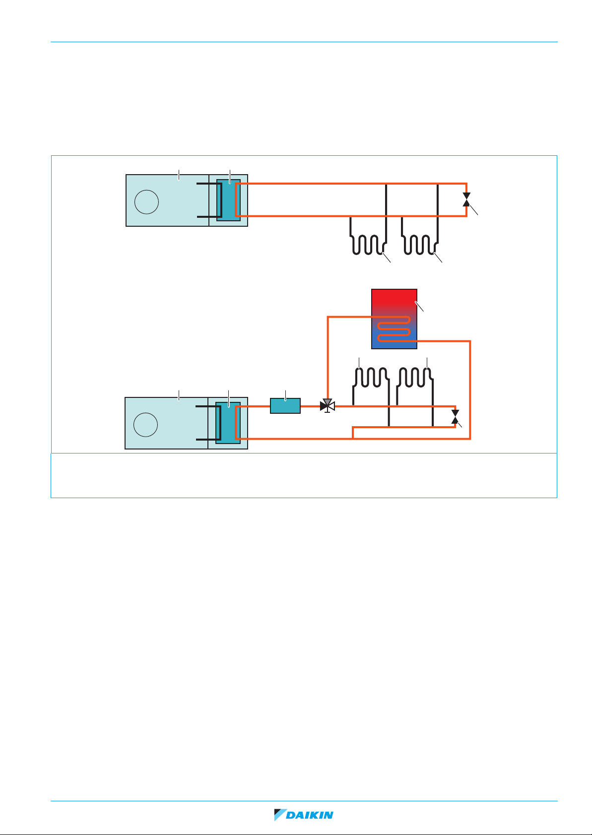
Figure 1 - General operation of the Daikin Altherma low temperature he at pump
1
1 52
2
4
3
3
6
3 3
4
1. Outdoor unit 4. By-pass
2. Plate Heat Exchanger 5. Backup Heater (optional)
3. Space heating 6. Domestic Hot Water Tank
In the refrigerant circuit, there is a compressor which will increase the pressure and thus increase the temperature of the refrigerant
before it's being exchanged with water in the plate heat exchanger. A water pump ensures flow in the water circuit.
Operation range can be found back in the engineering data book. The requested water temperatures for space heating and
domestic hot water are delivered by the heat pump operation and, were/when necessary, by assistance of the backup hea ter.
19/07/16 Page 13
Daikin Altherma Monobloc CA
ESIE15-08B | Part 1. Introduction 3. General operation of Daikin Altherma CA low temperatu re heat pump
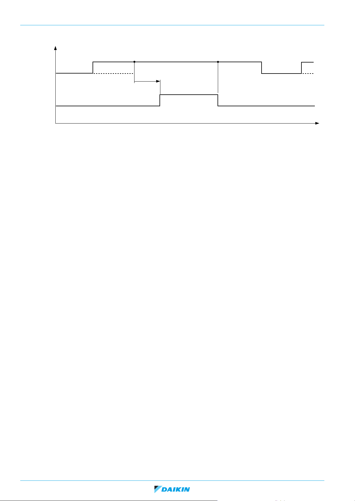
When the unit starts operation, following behaviour occurs:
Thermo
“OFF”
~ 3 min.
Sampling(*)
H2O pump
ON
OFF
ON
Remocon
“ON”
Sampling(*)
Decide thermo
“ON”
1 min.
Inverter control
Compressor
OFF
Pressure equalisation
(EV = 480 pls)
(*) H2O pump sampling operation only in case of leaving water temperature control (not in case of room temperature control).
t
When space heating thermo ON is decided and pump is working on ∆T control (default 5°C):
• The inverter water pump will gradually adjust its speed to reach and maintain the required delta T (this is the water temperature
difference between the leaving water and entering water (adju stable by setting)).
• The inverter compressor (after pressure equalisation) will gradually adjust its speed to reach and maintain the required water
temperature.
When the domestic hot water function is activated, the 3-way valve will switch over to the domestic hot water tank and space
heating side is closed. Domestic hot water and space heating cannot be active simultaneously. The 3-way valve will switch back
to space heating when domestic hot water setpoint is reached or when running timers are finished (refer to the Installer Reference
Guide for more details).
When the unit receives a thermo OFF signal:
• The compressor will stop its operation.
• The water pump will operate for some more minutes and eventually stop or start sampling.
Page 14 19/07/16
Daikin Altherma Monobloc CA
Y
Wh
at
d
a
n Er
r
Co
de
mp
mp
to
b
ESIE15-08B | Part 1. Introduction 4. How to use this book
4. How to use this book
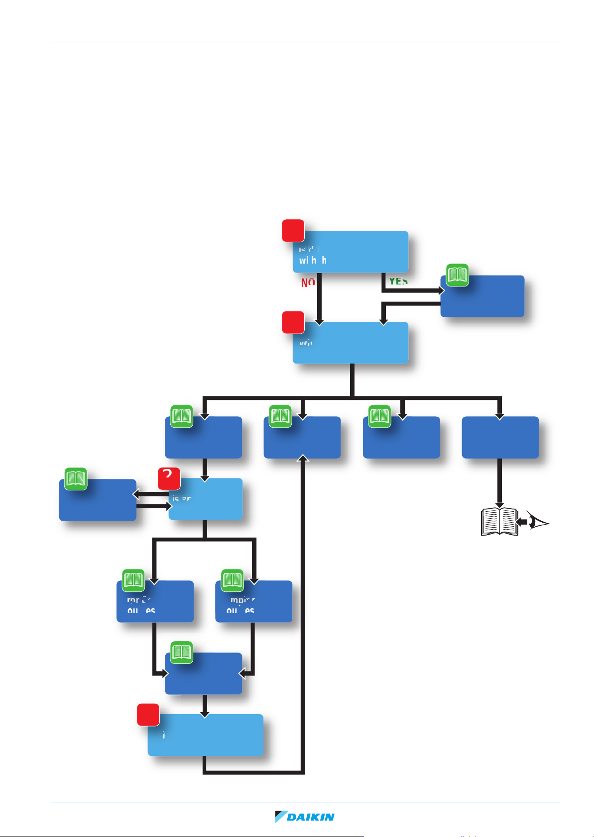
4.1. Interactive information flow
This Daikin product Service Manual is intended for professional use only. The actions described hereafter, are only to be performed
by qualified and certified persons, taking into account the safety precautions mentioned in this manual and the local regulations as
well.
By following the diagram below, the reader can find the relevant information related to his/her task. The digital (pdf) version of this
book allows direct page access through all active links. When Adobe Acrobat Reader is used, the <Alt> + <Back Arrow> keys can
be used to return to the previously viewed page.
?
Is this your 1st encounter
with this particular unit?
How to retrieve
Error Codes
YES
PART 2
Troubleshooting
?
Is an Error Code
displayed?
NO
NO
?
What do you need to do?
PART 3
Repair
YES
PART 4
Maintenance
General
operation
Installation
Refer to:
Installation Manual
or
Installer Reference Guide
Error Code based
troubleshooting
Component
checklist
Symptom based
troubleshooting
?
Is repair necessary?
e
19/07/16 Page 15

Daikin Altherma Monobloc CA
ESIE15-08B | Part 1. Introduction 4. How to use this book
4.2. Parts of the book
This Daikin product Service Manual is intended for professional use only. The actions described hereafter, are only to be performed
by qualified and certified persons, taking into account the safety precautions mentioned in this manual and the local regulations as
well.
As can be observed from the Table of Contents, this ma nual is split up into several chapters:
4.2.1. The introduction chapter
The chapter "Introduction" on page 9 includes the safety precautions, this topic and the general operation description of the
product(s) this manual refers to.
4.2.2. The troubleshooting chapter
The chapter "Troubleshooting" on page 17 not only deals with the methods to recognize and resolve occurring error codes; it also
describes the methods how to solve a problem that does not immediately trigger an error code. Such problems are referred to as
'symptom based'. Both the error code based and symptom based troubleshooting tables, indicate possible causes, the necessary
checks and in case required, how to repair. The possible causes have been sorted to probability of occurrence and speed of
execution.
4.2.3. The repair chapter
The chapter "Repair" on page 105 handles the remo val and replacement of the major components in the product and discusses
cleaning methods as well if applicable, such as for filters. Where applicable, refrigerant handling precautions are mentioned for
certain actions; please consider these carefully for your own safety.
4.2.4. The maintenance chapter
The chapter "Maintenance" on page 135 of this manual describes the maintenance intervals and procedures to be performed on
the product. Remember that a well maintained product, is a more reliable and efficient product.
4.2.5. Appendices
Finally, the service manual provides in chapter "Appen dix" on page 139 valuable reference data such as piping/wiring diagrams,
field settings overview and a checklist to be filled in when you need to escalate an issue to your dealer.
4.3. Contact information
This manual has been made with much care and effort. Use it in your daily jobs, as it has been made for you.
Despite our efforts, there is always a chance some cleric or other mistake has been made during the creation of this manual. We
kindly ask you to send the found mistakes, or remarks for improvement, to the no-reply email address
servicemanual@daikineurope.com.
Page 16 19/07/16
Daikin Altherma Monobloc CA
ESIE15-08B | Part 2. Troubleshooting 1. Error codes
Part 2. Troubleshooting
This part contains the following chapters:
1. Error codes .................................................................................17
2. Error code based troubleshooting...............................................19
3. Symptom based troubleshooting ................................................49
4. Component checklist - Water Circuit.......................................... 65
5. Component checklist - Refrigerant Circuit.................................. 88
1. Error codes
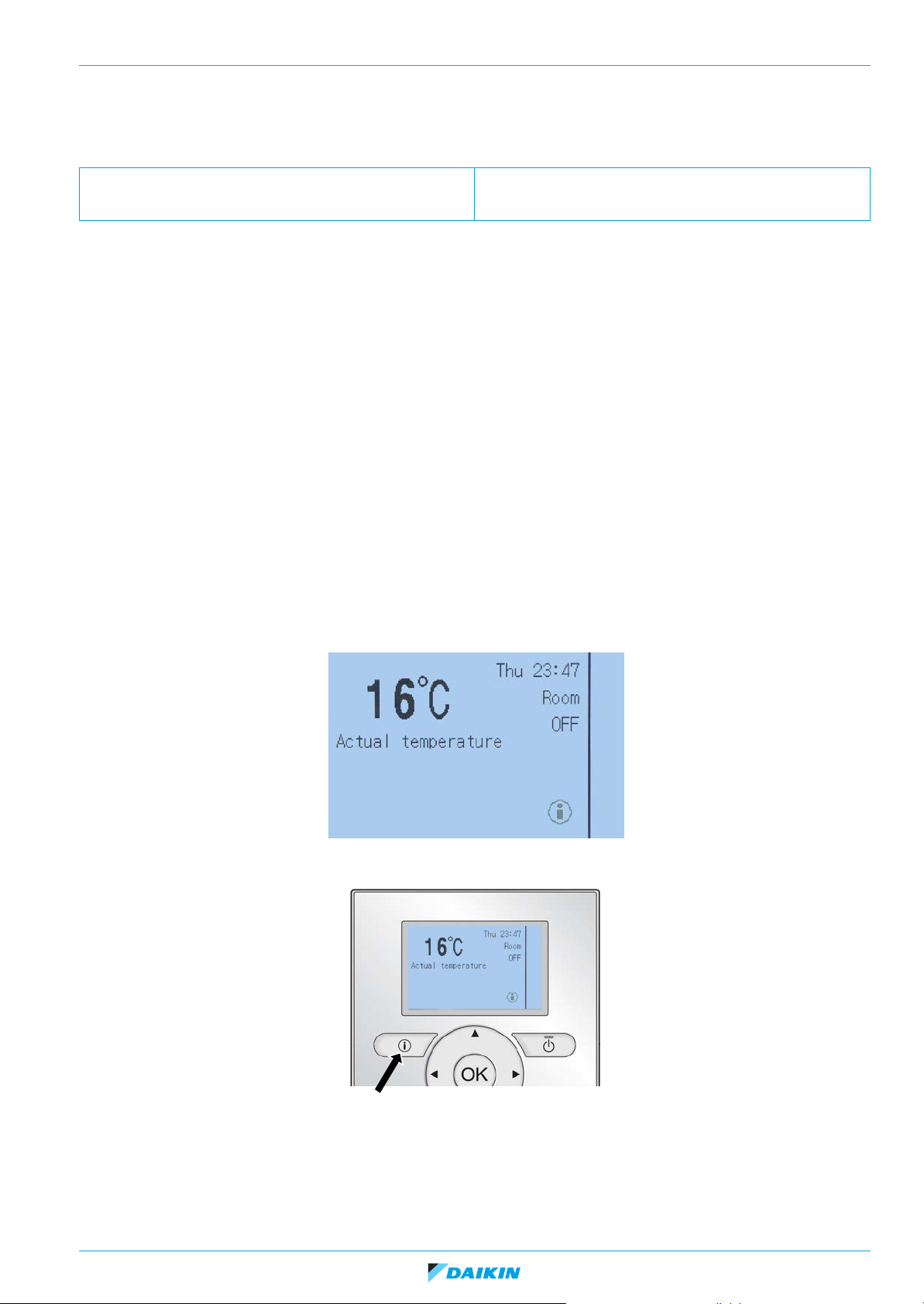
1.1. How to retrieve error codes
When a problem happens, an error code appears on the user interface. It is important to understand the problem and to take
countermeasure before resetting the error code.
For the Altherma Monobloc CA, there are 3 types of troubleshooting codes:
1. Error: a severe problem, system will preventively shut down to prevent further breakdown and the error code will be displayed
on the user interface where it is visible for the end user. Installer should be notified to come on site and repair the problem. All
errors are listed in the Error History [6.3.1] which is only visible when in installer level.
2. Warning: not a severe problem but might lead to an error in case it occurs a number of times within a certain time frame. The
system will not stop but the i-symbol (information) will be blinking. All warnings are listed in the Warning History [6.3.3] which
is only visible when in installer level.
3. Caution: not a severe problem but a sort of alert that the unit will start monitoring a certain event, which might over time result
in an error or a warning. Cautions are not listed.
You can see the error code / warning by pressing the i-button.
Now you can read the error code / warning and a short indication about the problem.
19/07/16 Page 17
Daikin Altherma Monobloc CA
ESIE15-08B | Part 2. Troubleshooting 1. Error codes
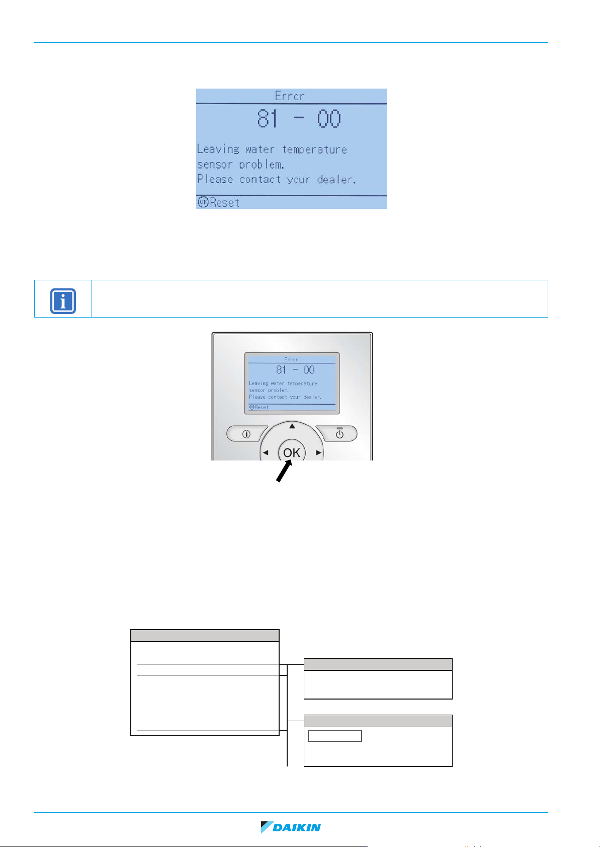
If an error is present, it will immediately be displayed on the user interface screen: for more information about troubleshooting, refer
to "Error code based troubleshooting" on page 19.
1.2. How to reset error codes
When the problem is solved, you can reset the error by pushing the OK-button unless otherwise mentioned on the screen.
INFORMATION
For U3 error for example, you need to be in installer mode to reset.
1.3. History of error codes and warnings
The (history of) error codes can be retrieved through the indoor unit (user interface).
The user interface can remember up to 20 error codes.
They are split up in an error history list (which only lists errors) and a warning history list (which lists warnings and some
cautions). Both lists are always visible when in installer level. End user + will only see error history in case the error occurs so
he can inform the installer, first level of end user cannot see the history.
They can be found on the following location:
[6] Information
Sensor information
Energy metering
Error handling
User permission level
Actuators
Operation modes
Running hours
Version
[6.2] Energy metering
Consumed elec.
Produced energy
[6.3] Error information
Error history
Contact/helpdesk number
Warning history
Page 18 19/07/16
Daikin Altherma Monobloc CA
ESIE15-08B | Part 2. Troubleshooting 2. Error code based troubleshooting
2. Error code based troubleshooting
Overview of error codes:
“AA-00” – Back up heater safety error............................................19
“AC-00” – Booster heater thermal protector is open.......................20
“AH-00” – Disinfection operation error............................................21
“AJ-03” – Domestic hot water heat duration is too long (warning)..21
“A1-00” – Zero cross detection problem .........................................22
“A1-01” – Hydro PCB A1P abnormality ..........................................22
“A5-00” – Freeze-up prevention (refrigerant)..................................22
“CJ-02” – User interface room temperature error ...........................23
“C0-00” – Flow sensor error............................................................23
“C0-01” – Flow switch warning .......................................................23
“C0-02” – Flow switch error ............................................................24
“C0-01” – Flow switch warning .......................................................23
“EA-00” – 4-way valve malfunction........................................ .........24
“EC-00” – Domestic hot water temperature error ...........................25
“E1-00” – Outdoor unit PCB abnormality........................................25
“E3-00” – High pressure abnormality (refrigerant)..........................26
“E4-00” – Actuation of sensor (low pressure) .................................26
“E5-00” – Compressor motor lock...................................................27
“E6-00” – Compressor startup defect..............................................27
“E7-00” – Malfunction of outdoor unit fan motor .............................28
“E8-00” – Power input overvoltage .................................................28
“E9-00” – Expansion valve abnormality..........................................29
“F6-00” – Abnormal high pressure in cooling..................................30
“HC-00” – Domestic hot water temperature error ...........................31
“H0-00” – Voltage/current sensor problem......................................31
“H1-00” – Optional temperature sensor error (indoor ambient) ......32
“H3-00” – High pressure switch abnormality...................................32
“H6-00” – Malfunction of position detection sensor ........................32
“H8-00” – Malfunction of compressor input (CT) system................33
“H9-00” – Outdoor air thermistor (R3T) abnormality.......................33
“JA-00 / JI-00” – Pressure sensor abnormality ...............................34
“J3-00” – Discharge thermistor (R1T) abnormality .........................34
“J6-00” – Heat exchanger thermistor (R2T) abnormality ................34
“J7-00” – Malfunction of intermediate heat exchanger thermistor ..35
“J8-00” – Malfunction of liquid pipe thermistor................................35
“LC-00” – Transmission system abnormality ..................................35
“L1-00” – Outdoor main PCB abnormality.......................................36
“L3-00” – Switch box temperature abnormality.............................. 36
“L4-00” – Radiation fin temperature abnormality............................ 37
“L5-00” – Output overcurrent detection.......................................... 37
“L8-00” – Electronic thermal overload............................................ 38
“PJ-00” – Defective capacity setting............................................... 38
“UA-00” – Indoor-Outdoor PCB combination ................................. 38
“UA-16” – Communication warning between hydro PCB A1P and
control box PCB............................................................................. 39
“UA-21” – PCB combination malfunction ....................................... 39
UA-22” – Communication warning between control box and option
box ................................................................................................. 40
“UA-60” – PCB combination malfunction ....................................... 40
“U0” – Refrigerant shortage ........................................................... 41
“U7-00” – Transmission malfunction between outdoor unit main PCB
and inverter PCB............................................................................ 43
“UF-00” – Communication error between hydro PCB A1P and out-
door main PCB or gas shortage..................................................... 41
“U3-00” – Abnormal stop of underfloor heating dry-out scheduled
operation........................................................................................ 42
“U4-00” – Defective indoor-outdoor transmission .......................... 42
“U5-00” – Transmission error between user interface and hydro PCB
A1P ............................................................................................... 43
“U7-00” – Transmission malfunction between outdoor unit main PCB
and inverter PCB............................................................................ 43
“7H-04” – Water flow abnormality during DHW operation.............. 44
“7H-05” – Water flow abnormality during space heating operation 45
“7H-06” – Water flow abnormality during defrost/cooling operation45
“8F-00” – Backup heater outlet water temperature error during
domestic hot water operation......................................................... 45
“8H-00” – Backup heater outlet water temperature error............... 46
“80-00” – R4T entering water thermistor abnormality .................... 46
“81-00” – Leaving water thermistor R1T abnormality..................... 46
“89-01” – Plate heat exchanger freeze-up error............................. 47
“89-02” – Plate heat exchanger freeze-up warning during space
heating / DHW production.............................................................. 47
“89-03” – Plate heat exchanger warning during defrost................. 48
2.1. “AA-00” – Back up heater safety error
Trigger Effect Reset
Thermal protector Q1L is activated (open
circuit). Water temp > 90°C.
Possible cause Check Corrective action
Air in water circuit / backup heater. Check if all air purge valves are open.
Increased water temperature by external
heat source.
Faulty thermal protector Q1L. Check thermal protector backup heater
Faulty outlet backup heater thermistor. Check outlet backup heater thermistor
Faulty outlet water heat exchanger thermistor.
Faulty backup heater assy. Check backup heater kit (see page 65). Replace the backup heater assy when
Unit will stop operating.
Check if air purge valves are installed on
all highest points of the field installed
water circuit.
Check if another heat source is installed
on the same water circuit.
Q1L (see page 79).
(see page 70).
Check outlet water heat exchanger ther-
mistor (see page 70).
Power reset + reset via user interface +
pressing the button on the Q1L (if
activated).
Purge the unit and field supplied water
system and backup heater. Refer to the
Installer Reference Guide.
Correct hydraulic field circuit. Refer to the
Installer Reference Guide.
Replace thermal protector backup heater
Q1L when required.
Replace outlet backup heater thermistor
when required.
Replace outlet water heat exchanger thermistor when required.
required.
19/07/16 Page 19
Daikin Altherma Monobloc CA
ESIE15-08B | Part 2. Troubleshooting 2. Error code based troubleshooting
Faulty hydro PCB A1P. Check if the alive led is blinking in regular
intervals.
Check if the correct spare part is installed.
Check if hydro PCB A1P receives power.
Adjust the power to the PCB.
Replace hydro PCB A1P when alive led is
not blinking in regular intervals.
Adjust software of hydro PCB A1P or
install correct spare part when required.
Faulty wiring between outdoor unit - Control box - DHW tank.
Check wiring (power supply, connections
between PCB’s, ...).
Adjust wiring when required.
Faulty backup heater . Check booster heater (see page 69). Replace the booster heater when required
(see Installer reference guide of the water
tank).
Water pressure is too low. Check the water pressure on the pressure
gauge.
Increase water pressure till ~2 bar. Refer
to the Installer Reference Guide.
Check for possible water leaks.
Water flow is too low. Check the minimum water flow required
for the system. Refer to Installer Refer-
Adjust system to meet the water flow
requirements.
ence Guide.
Faulty extension PCB A4P. Check PCB A4P (see page86).
Check if the correct spare part is installed.
Replace extension PCB A4P when
required.
2.2. “AC-00” – Booster heater thermal protector is open
Trigger Effect Reset
Thermal protector Q2L/Q3L is activated
(open circuit).
Water temperature > 85°C.
Unit will immediately stop operation. Manual reset via user interface.
Possible cause Check Corrective action
Wrong settings. Check settings related to hot water tank (is
tank connected and is booster heater used).
Tank clixon Q2L tripped. Check if relay K3M is open. Reset the tank clixon.
Incorrect parameter of solar pump station. Check maximum tank temperature of solar
Air in water circuit/Booster heater Check if all air purge valves are open.
Increased water temperature by external
heat source.
Faulty thermal protector Q1L. Check thermal protector booster heater
Faulty hydro PCB A1P. Check if the alive led is blinking in regular
Faulty wiring between outdoor unit - Control
box - DHW tank.
Faulty booster heater. Check booster heater (see page 69).
Water pressure is too low. Check the water pressure on the pressure
Water flow is too low. Check the minimum water flow required for
pump station.
Check if air purge valves are installed on all
highest points of the field installed water cir-
cuit.
Check if another heat source is installed on
the same water circuit.
Q2L/Q3L (see page 69).
intervals.
Check if the correct spare part is installed.
Check if
Check wiring (power supply, connections
between PCB's, ...).
gauge.
the system. Refer to Installer Reference
Guide.
hydro PCB A1P receives power.
Faulty extension PCB A4P. Check PCB A4P (see page86).
Check if the correct spare part is installed.
Correct settings according to Installer Reference Guide.
Set maximum tank temperature to a reasonable value.
Purge the unit and field supplied water system and backup heater when required. Refer
to the Installer Reference Guide.
Correct hydraulic field circuit. Refer to the
Installer Reference Guide.
Replace thermal protector booster heater
when required.
Adjust the power to the PCB.
Replace hydro PCB A1P when alive led is
not blinking in regular intervals.
Adjust software of hydro PCB A1P or install
correct spare part when required.
Adjust wiring when required.
Replace the booster heater
(see Installer reference guide of the water
tank).
Increase water pressure till ~2 bar. Refer to
the Installer Reference Guide.
Check for possible water leaks.
Adjust system to meet the water flow
requirements
Replace extension PCB A4P when
required.
when required
Page 20 19/07/16
Daikin Altherma Monobloc CA
ESIE15-08B | Part 2. Troubleshooting 2. Error code based troubleshooting
2.3. “AH-00” – Disinfection operation error
Trigger Effect Reset
Disinfection setpoint is not reached or not
kept at required temperature long enough.
Possible cause Check Corrective action
Large hot water quantity has been tapped
during / before disinfection.
Backup heater is restricted du ri ng di s in fection.
Faulty water tank thermistor R5T. Check thermistor R5T (see page 70). Replace thermistor R5T when required
Tank setting not OK. Check settings regarding tank. Change settings.
Backup heater not allowed. Check setting backup heater (e.g. [4-00]). Change settings.
Faulty hydro PCB A1P. Check if the alive led is blinking in regular
Faulty extension PCB A4P. Check PCB A4P (see page 86).
Booster heater not allowed. Check all electrical heater related settings
Unit will continue operating. Auto-reset when next disinfection is com-
pleted.
Check when the disinfection is scheduled
(schedule it when there is littl e c ha n c e
that water will be tapped so that the disinfection can finish in time).
Check the backup heater settings [4-00]
till [4-04]. Refer to the Installer Reference
Guide.
intervals.
Check if the correct spare part is installed.
Check if hydro PCB A1P receives power .
Check if the correct spare part is installed.
(e.g.[4-00])
Adjust schedule timer and/or related settings. Refer to the Installer Reference
Guide.
Adjust related settings. Refer to the
Installer Reference Guide.
(see page 124).
Adjust the power to the PCB.
Replace hydro PCB A1P when alive led is
not blinking in regular intervals.
Adjust software of hydro PCB A1P or
install correct spare part when require d.
Replace extension PCB A4P when
required.
Change settings when required.
2.4. “AJ-03” – Domestic hot water heat duration is too long (warning)
Trigger Effect Reset
DHW heat-up > 6 hours. Unit switches to space heating for 3
hours.
Possible cause Check Corrective action
Faulty backup heater. Check backup heater (see page 65). Replace backup heater when required.
Faulty or disturbance of the power supply.
(Imbalance > 10%) Power drop.
Short circuit.
Blown fuse. Check fuses on PCB's. Replace fuses when required.
Too large DHW consumption. Lower DHW consumption.
Faulty 3-way valve. Check 3-way valve (see page 84). Replace 3-way valve when required.
Leaking field installed DHW tap. Check installation. Refer to Installer Ref-
Backup heater not allowed. Check setting backup heater (e.g. [4-00]). Change settings of backup heater.
Mismatch between software ID and EEP-
ROM on the hydro PCB A1P or User
Interface
Faulty booster heater. Check booster heater (see page 69).
Booster heater not allowed. Check all electrical heater related settings
Check if the power supply is conform with
regulations. No fluctuations in frequency.
erence Guide.
Confirm if the software and EEPROM on
hydro PCB A1P [Menu structure 6.8.2]
and User Interface [Menu structure 6.8.1]
correspond with the detailed information
given in the Update work instruction.
(e.g.[4-00])
Automatic reset via user interface.
Adjust power supply when required.
Power reset via outdoor unit.
Fix the leak.
Update hydro PCB A1P and User Interface again, do not forget to select "Reset
to factory settings" at the beginning of the
update procedure.
Replace the booster heater
(see Installer reference guide of the water
tank).
Change settings when required.
when required
19/07/16 Page 21
Daikin Altherma Monobloc CA
ESIE15-08B | Part 2. Troubleshooting 2. Error code based troubleshooting
2.5. “A1-00” – Zero cross detection problem
Trigger Effect Reset
Multiple zero-cross is detected in approximately 10 continuous seconds.
Unit will stop operating. Manual reset via user interface.
Possible cause Check Corrective action
Faulty wiring to hydro PCB A1P. Check wiring to PCB A1P. Adjust wiring when required.
Faulty hydro PCB A1P. Check if the alive led is blinking in regular
intervals.
Check if the correct spare part is installed.
Check if hydro PCB A1P receives power.
Faulty or disturbance of the power supply.
(Imbalance > 10%) Power drop.
Short circuit.
Check if the power supply is conform wit h
regulations. No fluctuations in frequency.
Adjust the power to the PCB.
Replace hydro PCB A1P when alive led is
not blinking in regular intervals.
Adjust software of hydro PCB A1P or
install correct spare part when required.
Adjust power supply when required.
Power reset via outdoor unit.
2.6. “A1-01” – Hydro PCB A1P abnormality
Trigger Effect Reset
Hydro PCB A1P detects EEPROM is
abnormal.
Unit will stop operating. Via power reset + via user interface.
Possible cause Check Corrective action
Faulty hydro PCB A1P. Check if the alive led is blinking in regular
intervals.
Check if the correct spare part is installed.
Check if hydro PCB A1P receives power.
Adjust the power to the PCB.
Replace hydro PCB A1P when alive led is
not blinking in regular intervals.
Adjust software of hydro PCB A1P or
install correct spare part when required.
2.7. “A5-00” – Freeze-up prevention (refrigerant)
Trigger Effect Reset
Heat exchanger thermistor measures
temperature below 0°C, 15 tim e s in 300
min.
Condensing temperature reaches a temperature of 59,5°C, 15 times in 300 min.
Possible cause Check Corrective action
Refrigerant circuit is clogged. Check for possible blockage (blockage
Faulty expansion valve. Check expansion valve (see page 97). Replace expansion valve when required
Faulty outdoor unit thermistor. Check outdoor unit thermistors (see
Water pressure is too low Check the water pressure on the pressure
Unit will stop. Manual reset via user interface.
Replace the blocked part.
can be checked by measuring the refrigerant/pipe temperature. Sudden drop in
temperature could indicate a blockage
(Remark: this is not valid for the expansion valve)).
(see page 131).
Replace outdoor unit thermistor when
page 88).
gauge.
required (see page 124).
Increase water pressure till ~2 bar. Refer
to the Installer Reference Guide.
Check for possible water leaks.
Page 22 19/07/16
Daikin Altherma Monobloc CA
ESIE15-08B | Part 2. Troubleshooting 2. Error code based troubleshooting
Water flow is too low. Check the minimum water flow required
for the system. Refer to Installer Refer-
ence Guide.
Closed valve in water circuit Check if all valves are open. Adjust/open valve.
Air in water circuit. Check if all air purge valves are open.
Check if air purge valves are installed on
all highest points of the field installed
water circuit.
Adjust system to meet the water flow
requirements.
Purge air out of unit and field supplied
water system and backup heater . Refer to
the Installer Reference Guide.
2.8. “CJ-02” – User interface room temperature error
Trigger Effect Reset
Room temperature thermistor of user
interface detects an abnormal value (open
or short circuit).
Possible cause Check Corrective action
Faulty room thermistor of user interface. Check room thermistor read out value via
Unit will keep operating. Auto-reset.
Replace user interface or replace hydro
the user interface and compare with
actual room temperature.
PCB A1P when required.
2.9. “C0-00” – Flow sensor error
Trigger Effect Reset
Flow sensor still detects a water flow af t er
45 seconds when pump has stopped.
Possible cause Check Corrective action
Water flow caused by external pump. Check if another (external) pump is
Faulty flow sensor. Check flow sensor (see page 81). Replace flow sensor when required.
Faulty hydro PCB A1P. Check if the alive led is blinking in regular
Faulty wire harness Check the wire harness and the connec-
Unit will stop operating. Manual reset via user interface.
Correct hydraulic field circuit. Refer to the
installed on the same water circuit.
intervals.
Check if the correct spare part is installed.
Check if hydro PCB A1P receives power .
tion to hydro PCB A1P.
Installer Reference Guide.
If flow sensor failed due to contamination,
check for source of contamination and
consider to install an additional water fil-
ter.
Adjust the power to the PCB.
Replace hydro PCB A1P when alive led is
not blinking in regular intervals.
Adjust software of hydro PCB A1P or
install correct spare part when require d.
Replace the wire harness when required.
2.10. “C0-01” – Flow switch warning
Trigger Effect Reset
Unit detects flow when pump is not running.
Possible cause Check Corrective action
See possible causes for C0-02.
19/07/16 Page 23
Unit will stop operating. Auto reset.
Daikin Altherma Monobloc CA
ESIE15-08B | Part 2. Troubleshooting 2. Error code based troubleshooting
2.11. “C0-02” – Flow switch error
Trigger Effect Reset
Flow switch warning triggered too often.
Unit detects flow when pump is not run-
ning.
Possible cause Check Corrective action
Faulty flow switch. Check flow switch (see page 83). Replace flow switch when required.
Water flow caused by external pump Check if another (external) pump is
Faulty hydro PCB A1P. Check if the alive led is blinking in regular
Faulty wire harness Check the wire harness and the connec-
Unit will stop operating. Manual reset via user interface.
Correct hydraulic field circuit. Refer to
installed in the same water circuit.
intervals.
Check if the correct spare part is installed.
Check if hydro PCB A1P receives power.
tion to hydro PCB A1P.
Installer Reference Guide.
Adjust the power to the PCB.
Replace hydro PCB A1P when alive led is
not blinking in regular intervals.
Adjust software of hydro PCB A1P or
install correct spare part when required.
Replace the wire harness when required.
2.12. “C4-00” – Refrigerant liquid thermistor R3T abnormality
Trigger Effect Reset
Thermistor detects an abnormal value
(open or short circuit).
Unit will stop operating. Auto-reset when problem is solved.
Possible cause Check Corrective action
Faulty refrigerant liquid thermistor R3T. Check refrigerant liquid thermistor R3T
(see page 70).
Faulty hydro PCB A1P. Check if the alive led is blinking in regular
intervals.
Check if the correct spare part is installed.
Check if hydro PCB A1P receives power.
Replace refrigerant liquid thermistor R3T
when required (see page 124).
Adjust the power to the PCB.
Replace hydro PCB A1P when alive led is
not blinking in regular intervals.
Adjust software of hydro PCB A1P or
install correct spare part when required.
2.13. “EA-00” – 4-way valve malfunction
Trigger Effect Reset
After an operation of 5 min, following condition occurs over 10 min:
Heating: Hydro-box heat exchanger temperature minus outlet water temperature <
-10°C.
Unit will stop operating. Manual reset via user interface.
Possible cause Check Corrective action
Faulty outlet water heat exchanger thermistor.
Faulty refrigerant liquid side thermistor. Check refrigerant liquid side thermistor
Check outlet water heat exchanger thermistor (see page 70).
(see page 70).
Replace thermistor when required (see
page 124).
Replace thermistor when required (see
page 124).
Replace hydro PCB A1P when required.
Page 24 19/07/16
Daikin Altherma Monobloc CA
ESIE15-08B | Part 2. Troubleshooting 2. Error code based troubleshooting
Faulty outdoor main PCB. Check if the alive led is blinking in regular
intervals.
Check if the correct spare part is installed.
Check if the outdoor main PCB receives
power.
Faulty 4-way valve coil/ wire harness. Check 4-way valve coil/ wire harness (see
page 99).
Faulty 4-way valve body Check 4-way valve body (see page 99). Replace 4-way valve body when required
Refrigerant shortage. Check for refrigerant shortage (see
page 106).
Perform leak test.
Refrigerant contaminated Check quality of the refrigerant Replace refrigerant when required.
Faulty stop valve Check stop valves. Replace stop valve when required.
Faulty hydro PCB A1P. Check if the alive led is blinking in regular
intervals.
Check if the correct spare part is installed.
Check if hydro PCB A1P receives power .
Adjust the power to the outdoor main
PCB.
Replace outdoor main PCB (see
page 131) when alive led is not blinking in
regular intervals (see page 119).
Replace 4-way valve coil/ wire harnes s
when required (see page 127).
(see page 127).
If charge is lower than indicated on
name-plate, check for leaks and recharge
unit with correct amount of refrigerant.
Make sure your refrigerant system is dry
and clean before charging!
Adjust the power to the PCB.
Replace hydro PCB A1P when alive led is
not blinking in regular intervals.
Adjust software of hydro PCB A1P or
install correct spare part when require d.
2.14. “EC-00” – Domestic hot water temperature error
Trigger Effect Reset
Water tank thermistor detect s temperature
above 89°C.
Unit will continue operating. Auto-reset when trouble is solved.
Possible cause Check Corrective action
Increased water temp by external heat
source (solar panel).
Faulty water tank thermistor R5T. Check water tank thermistor (see
Faulty hydro PCB A1P. Check if the alive led is blinking in regular
Check if another heat source is installed
on the same water circuit.
page 70).
intervals.
Check if the correct spare part is installed.
Check if hydro PCB A1P receives power .
Correct hydraulic field circuit. Refer to the
Installer Reference Guide.
Replace thermistor R5T when required
(see page 124).
Adjust the power to the PCB.
Replace hydro PCB A1P when alive led is
not blinking in regular intervals.
Adjust software of hydro PCB A1P or
install correct spare part when require d.
2.15. “E1-00” – Outdoor unit PCB abnormality
Trigger Effect Reset
Outdoor main PCB detects that EEPROM
is abnormal.
Unit will stop operating. Manual reset via user interface.
Possible cause Check Corrective action
Faulty outdoor main PCB. Check if the alive led is blinking in regular
intervals.
Check if the correct spare part is installed.
Check if the outdoor main PCB receives
power.
Adjust the power to the outdoor main
PCB.
Replace outdoor main PCB when alive led
is not blinking in regular intervals (see
page 119).
19/07/16 Page 25
Daikin Altherma Monobloc CA
ESIE15-08B | Part 2. Troubleshooting 2. Error code based troubleshooting
External factor (e.g. electrical noise)
(cause when error is reset after power
reset, and error happens again after
awhile).
Faulty fan motor. Check fan motor (see page 103)
Faulty or disturbance of the power supply.
(Imbalance > 10%) Power drop.
Short circuit.
Check for source which could cause electrical interference.
Check fan motor connection and wiring.
Check if the power supply is conform wit h
regulations. No fluctuations in frequency.
Replace fan motor when required (see
page 116). Adjust wiring when required.
Adjust power supply when required.
Power reset via outdoor unit.
2.16. “E3-00” – High pressure abnormality (refrigerant)
Trigger Effect Reset
1. High pressure switch opens due to
pressure > 41,7 bar.
2. High pressure control (HP > 38 bar)
occurs 16 times within 300 minutes.
Possible cause Check Corrective action
Refrigerant overcharge. Check for refrigerant overcharge. Charge the correct refrigerant amount
Humidity in refrigerant (ice formation in
expansion valve).
Non condensables in refrigerant. Check for non condensables in refriger-
Refrigerant circuit is clogged. Check for possible blockage (blockages
Faulty pressure sensor. Check pressure sensor (see page 94). Replace the pressure sensor when
Faulty high pressure switch. Check high pressure switch (see
Stop valve is closed. Check if stop valve is open. Open stop valve when required.
Faulty fan motor. Check fan motor (see page 103)
Faulty outdoor main PCB. Check if the alive led is blinking in regular
Unit will stop operating. Manual reset via user interface.
when required.
Check for humidity in the refrigerant. In case of suspicion of humidity, recover
vacuum and recharge with virgin refrigerant.
In case of suspicion of non condensables
ant.
can be checked by measuring the refrigerant/pipe temperature. Sudden drop in
temperature could indicate a blockage
(remark: this is not valid for the expansi on
valve).
page 96).
Check fan motor connection and wiring.
intervals.
Check if the correct spare part is installed.
Check if the outdoor main PCB receives
power.
recover, vacuum and re charge with virgin
refrigerant.
Replace the blocked part.
required (see page 130).
Replace the high pressure switch when
required (see page 129).
Replace fan motor when required (see
page 116). Adjust wiring when required.
Adjust the power to the outdoor main
PCB.
Replace outdoor main PCB when alive led
is not blinking in regular intervals (see
page 119).
2.17. “E4-00” – Actuation of sensor (low pressure)
Trigger Effect Reset
When refrigerant pressure is below 1.2
bar for 5 minutes.
Possible cause Check Corrective action
Stop valve is closed. Check if stop valve is open. Open stop valve when required.
Page 26 19/07/16
Unit will stop operating. Manual reset via user interface.
Daikin Altherma Monobloc CA
ESIE15-08B | Part 2. Troubleshooting 2. Error code based troubleshooting
Bad contact through pressure sensor
cable.
Faulty pressure sensor. Check the pressure sensor (see page 94). Replace the pressure sensor when
Abnormal drop of low pressure, caused by
inadequate refrigerant, abnormal refrigerant piping system or faulty electronic
expansion valve.
Faulty outdoor main PCB. Check if the alive led is blinking in regular
Check if pressure sensor connector X17A
is properly connected to the outdoor PCB
board A1P.
Check for possible blockage. (blockages
can be checked by measuring the refrigerant/pipe temperature. Sudden drop in
temperature could indicate a blockage
(remark: this is not valid for the expansion
valve))
intervals.
Check if the correct spare part is installed.
Check if the outdoor main PCB receives
power.
Connect or replace sensor cable when
required.
required (see page 130).
Replace the blocked part.
Adjust the power to the outdoor main
PCB.
Replace outdoor main PCB when alive led
is not blinking in regular intervals (see
page 119).
2.18. “E5-00” – Compressor motor lock
Trigger Effect Reset
The motor rotor does not rotate when the
compressor is energized.
Unit will stop operating. Manual reset via user interface.
Possible cause Check Corrective action
Refrigerant circuit is clogged (HP - LP
>0,26MPa).
Faulty compressor . Check compressor (see page 91).
Stop valve is closed. Check if stop valve is open. Open stop valve when required.
Faulty inverter voltage output. Check if inverter output voltages have
Compressor turned off too fast. Wait for guard timer to pass (3 min).
Faulty outdoor inverter PCB. Check outdoor inverter PCB (see
Faulty expansion valve. Check expansion valve (see page 97). Replace expansion valve when required
Faulty 4-way valve. Check 4-way valve (see page 99). Replace 4-way valve when required (see
Check for possible blockage (blockages
can be checked by measuring the refrigerant/pipe temperature. Sudden drop in
temperature could indicate a blockage
(remark: this is not valid for the expansion
valve)).
Check compressor connection and wiring.
Check expansion valve operation (liquid
back issue).
Check refrigerant charge (see page 106)
+ check for leaks.
same amplitude.
page 101).
Check if the alive led is blinking in regula r
intervals.
Check if the correct spare part is installed.
Replace the blocked part.
Replace the compressor when required.
(see page 125).
Investigate the reason of breakdown.
Replace expansion valve when requ i r e d
(see page 131).
Fix the possible leak.
Replace outdoor inverter PCB when
required (see page 122).
Adjust the power to the outdoor inverter
PCB.
Replace outdoor inverter PCB when
required (see page 122).
(see page 131).
page 127).
2.19. “E6-00” – Compressor startup defect
Trigger Effect Reset
System detects that the current waveform
to the compressor has an abnormality, 16
times in 5 min.
19/07/16 Page 27
Unit will stop operating. Manual restart via user interface.
Daikin Altherma Monobloc CA
ESIE15-08B | Part 2. Troubleshooting 2. Error code based troubleshooting
Possible cause Check Corrective action
Faulty or disturbance of the power supply.
(Imbalance > 10%) Power drop.
Short circuit.
Faulty compressor. Check compressor (see page91).
Faulty expansion valve. After power reset, check if error occurs
Check if the power supply is conform wit h
regulations. No fluctuations in frequency.
Check compressor connection and wiring.
Check expansion valve operation (liquid
back issue).
Check refrigerant charge (see page 106)
+ check for leaks.
when compressor is not running: check
expansion valve (see page97).
Adjust power supply when required.
Power reset via outdoor unit.
Replace the compressor when required.
(see page 125).
Investigate the reason of breakdown.
Replace expansion valve when required
(see page 131).
Fix the possible leak.
Replace expansion valve when required
(see page 131).
2.20. “E7-00” – Malfunction of outdoor unit fan motor
Trigger Effect Reset
When for 16 times, the fan runs with
speed less than a specified one for 15
seconds or more when the fan motor running conditions are met.
Unit will stop operating. Manual reset via user interface.
Possible cause Check Corrective action
Faulty fan motor. Check fan motor (see page 103)
Check fan motor connection and wiring.
Faulty outdoor inverter PCB. Check outdoor inverter PCB (see
page 101).
Check if the alive led is blinking in regular
intervals.
Check if the correct spare part is installed.
Blowout of fuse. Check fuse F6U on outdoor PCB A1P. Replace fuse when required.
Replace fan motor when required. Adjust
wiring when required.
Adjust the power to the outdoor inverter
PCB.
Replace outdoor inverter PCB when
required (see page 122).
2.21. “E8-00” – Power input overvoltage
Trigger Effect Reset
System detects overcurrent to compressor of >20A for >2.5 seconds, 16 times in
5 min.
Possible cause Check Corrective action
Faulty compressor. Check compressor (see page91).
Faulty power transistor
Faulty outdoor inverter PCB. Check outdoor inverter PCB (see
Unit will stop operating. Manual reset via user interface.
Replace the compressor when required.
Check compressor connection and wiring.
Check expansion valve operation (liquid
back issue).
Check refrigerant charge (see page 106)
+ check for leaks.
Check power transistor.
page 101).
Check if the alive led is blinking in regular
intervals.
Check if the correct spare part is installed.
(see page 125).
Investigate the reason of breakdown.
Replace expansion valve when required
(see page 131).
Fix the possible leak.
Replace power transistor when required.
Adjust the power to the outdoor inverter
PCB.
Replace outdoor inverter PCB when
required (see page 122).
Page 28 19/07/16
Daikin Altherma Monobloc CA
ESIE15-08B | Part 2. Troubleshooting 2. Error code based troubleshooting
Faulty outdoor main PCB. Check if the alive led is blinking in regular
intervals.
Check if the correct spare part is installed.
Check if the outdoor main PCB receives
power.
Faulty or disturbance of the power supply.
(Imbalance > 10%) Power drop.
Short circuit.
Check if the power supply is conform with
regulations. No fluctuations in frequency.
Adjust the power to the outdoor main
PCB.
Replace outdoor main PCB when alive led
is not blinking in regular intervals (see
page 119).
Adjust power supply when required.
Power reset via outdoor unit.
2.22. “E9-00” – Expansion valve abnormality
Trigger Effect Reset
1. No continuity of expansion valve.
2. Minimum expansion valve opening and
suction superheat < 4 K and discharge
superheat < 5 K.
Possible cause Check Corrective action
Faulty or disturbance of the power supply.
(Imbalance > 10%) Power drop.
Short circuit.
Faulty expansion valve. Check expansion valve (see page 97). Replace expansion valve when required.
Faulty thermistor on outdoor. Check thermistors on outdoor (see
Faulty pressure sensor / outdoor main
PCB.
Wet operation. Check for wet operation. (Wet operation
External factor (e.g. electrica l noi s e)
(cause when error is reset after power
reset, and error happens again after
awhile).
Faulty outdoor main PCB. Check if the alive led is blinking in regular
Unit will stop operating. Manual reset via user interface (power
reset might be necessary in case no common power supply was cause).
Check if the power supply is conform with
regulations. No fluctuations in frequency.
page 70).
Check pressure sensor (see page 94). Replace the pressure sensor (see
can be detected by checking the suction
superheat. If the suction superheat is 0°C
then liquid refrigerant is returning to the
compressor.)
Check for source which could cause electrical interference.
intervals.
Check if the correct spare part is installed.
Check if the outdoor main PCB receives
power.
Adjust power supply when required.
Power reset via outdoor unit.
Replace thermistors when required (see
page 124).
page 130) or outdoor main PCB (see
page 119) when required.
In case wet operation was detected confirm the cause:
• Refrigerant overcharge.
• Faulty expansion valve.
Adjust the power to the outdoor main
PCB.
Replace outdoor main PCB when alive led
is not blinking in regular intervals (see
page 119).
2.23. “F3-00” – Discharge pipe temperature control
Trigger Effect Reset
1. Discharge temperature > 110°C for 15
minutes.
2. Discharge temperature > 125°C.
Possible cause Check Corrective action
Refrigerant shortage (incorrect charge /
leakage blockage).
Faulty thermistor R2T. Check thermistor R2T (see page 88). Replace thermistor R2T when required
19/07/16 Page 29
Unit will stop operating. Manual reset via user interface -> only
possible when below 95°C.
Check for refrigerant shortage (see
page 106).
Perform leak test.
Repair the leak and charge the correct
amount of refrigerant (check nameplate).
(see page 124).
Daikin Altherma Monobloc CA
ESIE15-08B | Part 2. Troubleshooting 2. Error code based troubleshooting
Faulty compressor. Check compressor (see page91).
Check compressor connection and wiring.
Check expansion valve operation (liquid
back issue).
Check refrigerant charge (see page 106)
+ check for leaks.
Faulty expansion valve. Check expansion valve (see page 90 or
page 108).
Faulty 4-way valve. Check 4-way valve (see page 92). Replace 4-way valve when required (see
Faulty outdoor main PCB. Check if the alive led is blinking in regular
intervals.
Check if the correct spare part is installed.
Check if the outdoor main PCB receives
power.
Replace the compressor when required.
(see page 125).
Investigate the reason of breakdown.
Replace expansion valve when required
(see page 131).
Fix the possible leak.
Replace expansion valve when required.
page 127).
Adjust the power to the outdoor main
PCB.
Replace outdoor main PCB when alive led
is not blinking in regular intervals (see
page 119).
2.24. “F6-00” – Abnormal high pressure in cooling
Trigger Effect Reset
The temperature measured by the heat
exchanger thermistor rises above 60°C.
Unit will stop operating Auto reset when heat exchanger thermis-
tor drops below 50°C
Possible cause Check Corrective action
Installation space is not large enough. Check if the installation space is conform
with regulations. Refer to Installer Reference Guide.
Faulty fan motor. Check fan motor (see page 103)
Check fan motor connection and wiring.
Faulty expansion valve. Check expansion valve (see page 97). Replace expansion valve when required.
Faulty outdoor inverter PCB. Check outdoor inverter PCB (see
page 101).
Check if the alive led is blinking in regular
intervals.
Check if the correct spare part is installed.
Faulty outdoor main PCB. Check if the alive led is blinking in regular
intervals.
Check if the correct spare part is installed.
Check if the outdoor main PCB receives
power.
Faulty stop valve. Check stop valves. Replace stop valves when required.
Dirty heat exchanger. Check heat exchanger Clean heat exchanger when required.
Faulty heat exchanger thermistor R2T. Check heat exchanger thermistor R2T
(see page 88).
Refrigerant contaminated Check quality of the refrigerant Replace refrigerant when required.
Adjust installation space when required.
Replace fan motor when required (see
page 116). Adjust wiring when required.
Adjust the power to the outdoor inverter
PCB.
Replace outdoor inverter PCB when
required (see page 122).
Adjust the power to the outdoor main
PCB.
Replace outdoor main PCB when alive led
is not blinking in regular intervals (see
page 119).
Replace heat exchanger thermistor when
required (see page 124).
Make sure your refrigerant system is dry
and clean before charging!
Page 30 19/07/16
 Loading...