

Daikin EBLQ011CAW1, EBLQ014CAW1, EBLQ016CAV3, EBLQ011CAV3, EDLQ014CAV3 Installation Manual
...
Installation manual
Daikin Altherma low temperature monobloc
EBLQ011CAV3
EBLQ014CAV3
EBLQ016CAV3
EBLQ011CAW1
EBLQ014CAW1
EBLQ016CAW1
EDLQ011CAV3
EDLQ014CAV3
EDLQ016CAV3
EDLQ011CAW1
EDLQ014CAW1
EDLQ016CAW1
Installation manual
Daikin Altherma low temperature monobloc
English
A~E
a b* b
†
c d He eBe
D
HB HD H
U
(mm)
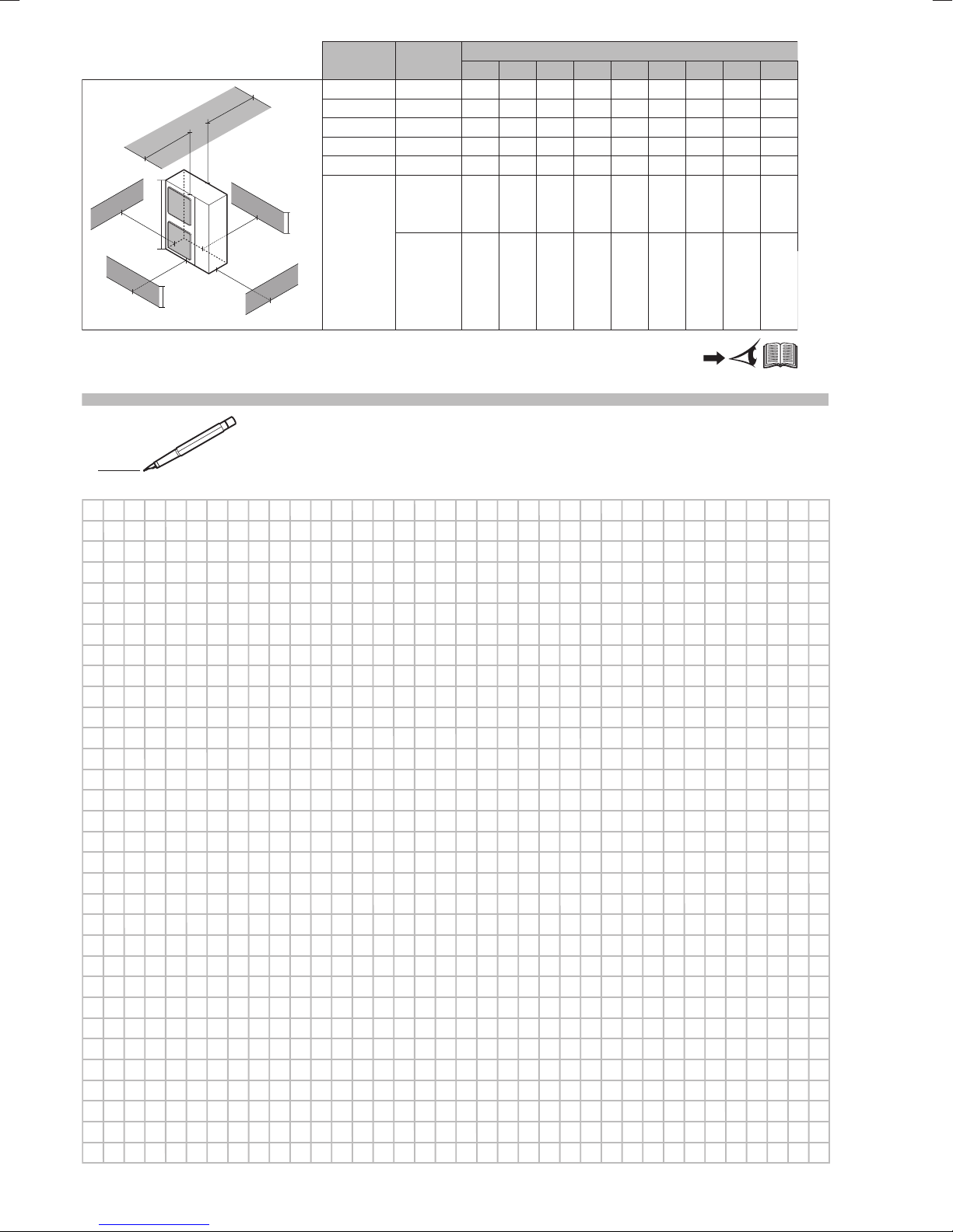
A, B, C — ≥500 ≥250 ≥100
A, B, C, E —
—
—
≥500 ≥250 ≥150 ≥1000 ≤500
≤500
D ≥500
≥500
D, E ≥1000 ≤500
B, D ≥250 ≥500
B, D, E ≥250
≥250
≥400
≥400
≥400
≥400
≥400
≥1000
≥150
≥150
≥150
≥150
≥150
≥150
≥150
≥1000
≥1000 ≥1000 ≤500
HD<H
U
HD<H
U
&
&
H
B>HU
HD>H
U
HB<H
U
*
,†
a
b*
,†
c
d
e
e
B
e
D
A
B
C
D
E
H
B
H
U
H
D
1
Directivelor, cu amendamentele respective.
<A>
<B>
<C>
DEKRA (NB0344)
2082543.0551-QUA/EMC
DAIKIN.TCF.025J02/02-2018
Direktive z vsemi spremembami.
Direktiivid koos muudatustega.
Директиви, с техните изменения.
Direktyvose su papildymais.
Direktīvās un to papildinājumos.
Smernice, v platnom znení.
18192021222324
Direktiver, med senere ændringer.
Direktiv, med företagna ändringar.
10111213141516
Directives, as amended.
deklaruje na własną i wyłączną odpowiedzialność, że urządzenia, których ta deklaracja dotyczy:
declară pe proprie răspundere că echipamentele la care se referă această declaraţie:
z vso odgovornostjo izjavlja, da je oprema naprav, na katero se izjava nanaša:
kinnitab oma täielikul vastutusel, et käesoleva deklaratsiooni alla kuuluv varustus:
декларира на своя отговорност, че оборудването, за коeто се отнася тази декларация:
visiška savo atsakomybe skelbia, kad įranga, kuriai taikoma ši deklaracija:
ar pilnu atbildību apliecina, ka tālāk aprakstītās iekārtas, uz kurām attiecas šī deklarācija:
vyhlasuje na vlastnú zodpovednosť, že zariadenie, na ktoré sa vzťahuje toto vyhlásenie:
tamamen kendi sorumluluǧunda olmak üzere bu bildirinin ilgili olduǧu donanımının aşaǧıdaki gibi olduǧunu beyan eder:
17
18
19
20
21
22
23
24
25
megfelelnek az alábbi szabvány(ok)nak vagy egyéb irányadó dokumentum(ok)nak, ha azokat előírás szerint használják:
spełniają wymogi następujących norm i innych dokumentów normalizacyjnych, pod warunkiem że używane są zgodnie z naszymi instrukcjami:
sunt în conformitate cu următorul (următoarele) standard(e) sau alt(e) document(e) normativ(e), cu condiţia ca acestea să fie utilizate în conformitate cu
instrucţiunile noastre:
skladni z naslednjimi standardi in drugimi normativi, pod pogojem, da se uporabljajo v skladu z našimi navodili:
on vastavuses järgmis(t)e standardi(te)ga või teiste normatiivsete dokumentidega, kui neid kasutatakse vastavalt meie juhenditele:
съответстват на следните стандарти или други нормативни документи, при условие, че се използват съгласно нашите инструкции:
atitinka žemiau nurodytus standartus ir (arba) kitus norminius dokumentus su sąlyga, kad yra naudojami pagal mūsų nurodymus:
tad, ja lietoti atbilstoši ražotāja norādījumiem, atbilst sekojošiem standartiem un citiem normatīviem dokumentiem:
sú v zhode s nasledovnou(ými) normou(ami) alebo iným(i) normatívnym(i) dokumentom(ami), za predpokladu, že sa používajú v súlade snašim
161718192021222324
návodom:
Direktiven, gemäß Änderung.
ürünün, talimatlarımıza göre kullanılması koşuluyla aşağıdaki standartlar ve norm belirten belgelerle uyumludur:
010203040506070809
25
Değiştirilmiş halleriyle Yönetmelikler.
25
Direktiver, med foretatte endringer.
Direktiivejä, sellaisina kuin ne ovat muutettuina.
v platném znění.
Smjernice, kako je izmijenjeno.
irányelv(ek) és módosításaik rendelkezéseit.
z późniejszymi poprawkami.
17
Directives, telles que modifiées.
Richtlijnen, zoals geamendeerd.
Directivas, según lo enmendado.
Direttive, come da modifica.
Οδηγιών, όπως έχουν τροποποιηθεί.
Directivas, conforme alteração em.
както е изложено в <A> и оценено положително от <B>
съгласно Сертификата<C>.
kaip nustatyta <A> ir kaip teigiamai nuspręsta <B> pagal
Sertifikatą<C>.
kā norādīts <A> un atbilstoši <B> pozitīvajam vērtējumam
saskaņā ar sertifikātu<C>.
ako bolo uvedené v <A> a pozitívne zistené <B> vsúlade
s osvedčením<C>.
<A>’da belirtildiği gibi ve <C>Sertifikasına göre <B>
tarafından olumlu olarak değerlendirildiği gibi.
Директив со всеми поправками.
21Забележка*
22Pastaba*
23Piezīmes*
24Poznámka*
25Not*
a(z) <A> alapján, a(z) <B> igazolta a megfelelést, a(z)
<C>tanúsítvány szerint.
zgodnie z dokumentacją <A>, pozytywną
opinią <B> i Świadectwem<C>.
aşa cum este stabilit în <A> şi apreciat pozitiv de<B>
în conformitate cu Certificatul<C>.
kot je določeno v <A> in odobreno s strani <B>
vskladu scertifikatom<C>.
nagu on näidatud dokumendis <A> ja heaks kiidetud
<B> järgi vastavalt sertifikaadile<C>.
16Megjegyzés*
17Uwaga*
18Notă*
19Opomba*
20Märkus*
Low Voltage 2014/35/EU
enligt <A> och godkänts av <B> enligt
Certifikatet<C>.
som det fremkommer i <A> og gjennom positiv
bedømmelse av <B> ifølge Sertifikat<C>.
jotka on esitetty asiakirjassa <A> ja jotka <B>
on hyväksynyt Sertifikaatin<C> mukaisesti.
jak bylo uvedeno v <A> a pozitivně zjištěno
<B> vsouladu sosvědčením<C>.
kako je izloženo u <A> i pozitivno ocijenjeno odstrane
Electromagnetic Compatibility 2014/30/EU *
заявляет, исключительно под свою ответственность, что оборудование, к которому относится настоящее заявление:
erklærer under eneansvarlig, at udstyret, som er omfattet af denne erklæring:
deklarerar i egenskap av huvudansvarig, att utrustningen som berörs av denna deklaration innebär att:
erklærer et fullstendig ansvar for at det utstyr som berøres av denne deklarasjon innebærer at:
ilmoittaa yksinomaan omalla vastuullaan, että tämän ilmoituksen tarkoittamat laitteet:
prohlašuje ve své plné odpovědnosti, že zařízení, k němuž se toto prohlášení vztahuje:
izjavljuje pod isključivo vlastitom odgovornošću da oprema na koju se ova izjava odnosi:
teljes felelőssége tudatában kijelenti, hogy a berendezések, melyekre e nyilatkozat vonatkozik:
09
10
11
12
13
14
15
16
estão em conformidade com a(s) seguinte(s) norma(s) ou outro(s) documento(s) normativo(s), desde que estes sejam utilizados de
acordo com as nossas instruções:
соответствуют следующим стандартам или другим нормативным документам, при условии их использования согласно нашим инструкциям:
overholder følgende standard(er) eller andet/andre retningsgivende dokument(er), forudsat at disse anvendes i henhold til vore instrukser:
respektive utrustning är utförd i överensstämmelse med och följer följande standard(er) eller andra normgivande dokument, under förutsättning att
användning sker i överensstämmelse med våra instruktioner:
respektive utstyr er i overensstemmelse med følgende standard(er) eller andre normgivende dokument(er), under forutssetning av at disse brukes i
henhold til våre instrukser:
vastaavat seuraavien standardien ja muiden ohjeellisten dokumenttien vaatimuksia edellyttäen, että niitä käytetään ohjeidemme mukaisesti:
za předpokladu, že jsou využívány v souladu s našimi pokyny, odpovídají následujícím normám nebo normativním dokumentům:
08091011121314
u skladu sa slijedećim standardom(ima) ili drugim normativnim dokumentom(ima), uz uvjet da se oni koriste u skladu s našim uputama:
15
ob upoštevanju določb:
vastavalt nõuetele:
следвайки клаузите на:
laikantis nuostatų, pateikiamų:
ievērojot prasības, kas noteiktas:
19202122232425
11Information*
12Merk*
održiavajúc ustanovenia:
bunun koşullarına uygun olarak:
delineato nel <A> e giudicato positivamente da<B>
secondo il Certificato<C>.
όπως καθορίζεται στο <A> και κρίνεται θετικά
από το <B> σύμφωνα με το Πιστοποιητικό<C>.
06Nota*
07Σημείωση*
<B> prema Certifikatu<C>.
13Huom*
14Poznámka*
15Napomena*
tal como estabelecido em <A> e com o parecer positivo
de <B> de acordo com o Certificado<C>.
как указано в <A> и в соответствии сположительным
решением <B> согласно Свидетельству<C>.
som anført i <A> og positivt vurderet af <B> ihenhold til
Certifikat<C>.
08Nota*
09Примечание*
10Bemærk*
Shigeki Morita
Director
Ostend, 3rd of April 2018
declares under its sole responsibility that the equipment to which this declaration relates:
erklärt auf seine alleinige Verantwortung daß die Ausrüstung für die diese Erklärung bestimmt ist:
déclare sous sa seule responsabilité que l'équipement visé par la présente déclaration:
verklaart hierbij op eigen exclusieve verantwoordelijkheid dat de apparatuur waarop deze verklaring betrekking heeft:
declara bajo su única responsabilidad que el equipo al que hace referencia la declaración:
dichiara sotto la propria responsabilità che gli apparecchi a cui è riferita questa dichiarazione:
δηλώνει με αποκλειστική της ευθύνη ότι ο εξοπλισμός στον οποίο αναφέρεται η παρούσα δήλωση:
Daikin Europe N.V.
CE - DECLARATION-OF-CONFORMITY CE - DECLARACION-DE-CONFORMIDAD CE - DECLARAÇÃO-DE-CONFORMIDADE CE - ERKLÆRING OM-SAMSVAR CE - IZJAVA-O-USKLAĐENOSTI CE - IZJAVA O SKLADNOSTI CE - ATITIKTIES-DEKLARACIJA
CE - KONFORMITÄTSERKLÄRUNG CE - DICHIARAZIONE-DI-CONFORMITA CE - ЗАЯВЛЕНИЕ-О-СООТВЕТСТВИИ CE - ILMOITUS-YHDENMUKAISUUDESTA CE - MEGFELELŐSÉGI-NYILATKOZAT CE - VASTAVUSDEKLARATSIOON CE - ATBILSTĪBAS-DEKLARĀCIJA
CE - DECLARATION-DE-CONFORMITE CE - ΔHΛΩΣΗ ΣΥΜΜΟΡΦΩΣΗΣ CE - OVERENSSTEMMELSESERKLÆRING CE - PROHLÁŠENÍ-O-SHODĚ CE - DEKLARACJA-ZGODNOŚCI CE - ДЕКЛАРАЦИЯ-ЗА-СЪОТВЕТСТВИЕ CE - VYHLÁSENIE-ZHODY
CE - CONFORMITEITSVERKLARING CE - FÖRSÄKRAN-OM-ÖVERENSTÄMMELSE CE - DECLARAŢIE-DE-CONFORMITATE CE - UYGUNLUK-BEYANI
01
02
declara sob sua exclusiva responsabilidade que os equipamentos a que esta declaração se refere:
EDLQ011CAV3*, EDLQ014CAV3*, EDLQ016CAV3*,
03
04
05
06
07
EBLQ011CAV3*, EBLQ014CAV3*, EBLQ016CAV3*,
08
are in conformity with the following standard(s) or other normative document(s), provided that these are used in accordance with our instructions:
der/den folgenden Norm(en) oder einem anderen Normdokument oder -dokumenten entspricht/entsprechen, unter der Voraussetzung, daß sie gemäß
EDLQ011CAW1*, EDLQ014CAW1*, EDLQ016CAW1*,
unseren Anweisungen eingesetzt werden:
EBLQ011CAW1*, EBLQ014CAW1*, EBLQ016CAW1*,
* = , , 1, 2, 3, ..., 9, A, B, C, ..., Z
01020304050607
under iagttagelse af bestemmelserne i:
enligt villkoren i:
gitt i henhold til bestemmelsene i:
noudattaen määräyksiä:
za dodržení ustanovení předpisu:
prema odredbama:
követi a(z):
zgodnie z postanowieniami Dyrektyw:
101112131415161718
sont conformes à la/aux norme(s) ou autre(s) document(s) normatif(s), pour autant qu'ils soient utilisés conformément à nos instructions:
conform de volgende norm(en) of één of meer andere bindende documenten zijn, op voorwaarde dat ze worden gebruikt overeenkomstig onze
instructies:
están en conformidad con la(s) siguiente(s) norma(s) u otro(s) documento(s) normativo(s), siempre que sean utilizados de acuerdo con nuestras
instrucciones:
sono conformi al(i) seguente(i) standard(s) o altro(i) documento(i) a carattere normativo, a patto che vengano usati in conformità alle nostre istruzioni:
είναι σύμφωνα με το(α) ακόλουθο(α) πρότυπο(α) ή άλλο έγγραφο(α) κανονισμών, υπό την προϋπόθεση ότι χρησιμοποιούνται
σύμφωνα με τις οδηγίες μας:
following the provisions of:
gemäß den Vorschriften der:
conformément aux stipulations des:
EN60335-2-40,
010203040506070809
în urma prevederilor:
as set out in <A> and judged positively by <B>
according to the Certificate<C>.
wie in <A> aufgeführt und von <B> positiv
beurteilt gemäß Zertifikat<C>.
tel que défini dans <A> et évalué positivement par <B>
conformément au Certificat<C>.
zoals vermeld in <A> en positief beoordeeld door <B>
overeenkomstig de bepalingen van:
siguiendo las disposiciones de:
secondo le prescrizioni per:
με τήρηση των διατάξεων των:
de acordo com o previsto em:
в соответствии с положениями:
01Note*
02Hinweis*
03Remarque*
04Bemerk*
overeenkomstig Certificaat<C>.
como se establece en <A> y es valorado
positivamente por <B> de acuerdo con el
Certificado<C>.
05Nota*
3PW57792-15J
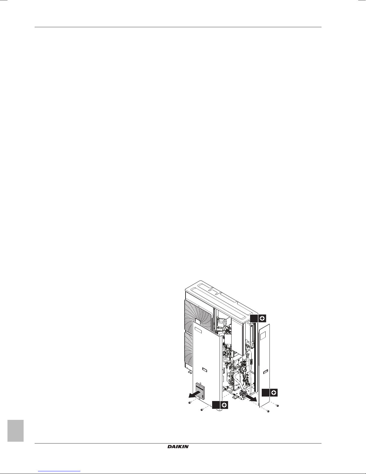
Table of Contents
1×
2×
2×
Table of Contents
1 About the documentation 4
1.1 About this document.................................................................. 4
2 About the box 4
2.1 Outdoor unit............................................................................... 4
2.1.1 To remove the accessories from the outdoor unit....... 4
3 Preparation 5
3.1 Preparing the installation site .................................................... 5
3.1.1 Installation site requirements of the outdoor unit ........ 5
3.2 Preparing water piping .............................................................. 5
3.2.1 To check the water volume and flow rate ................... 5
3.3 Preparing electrical wiring ......................................................... 6
3.3.1 Overview of electrical connections for external and
internal actuators ........................................................ 6
4 Installation 7
4.1 Opening the units ...................................................................... 7
4.1.1 To open the outdoor unit............................................. 7
4.1.2 To open the switch box cover of the outdoor unit ....... 7
4.2 Mounting the outdoor unit.......................................................... 7
4.2.1 To provide the installation structure............................ 7
4.2.2 To install the outdoor unit............................................ 7
4.2.3 To provide drainage.................................................... 7
4.2.4 To prevent the outdoor unit from falling over .............. 8
4.3 Connecting the water piping...................................................... 8
4.3.1 To connect the water piping........................................ 8
4.3.2 To connect the water piping to the backup heater...... 9
4.3.3 To protect the water circuit against freezing ............... 9
4.3.4 To fill the water circuit ................................................. 10
4.3.5 To insulate the water piping........................................ 10
4.4 Connecting the electrical wiring................................................. 10
4.4.1 To connect the electrical wiring on the outdoor unit.... 10
4.4.2 To connect the main power supply ............................. 11
4.4.3 To connect the user interface ..................................... 11
4.4.4 To connect the shut-off valve...................................... 12
4.4.5 To connect the domestic hot water pump................... 12
5 Configuration 13
5.1 Overview: Configuration ............................................................ 13
5.1.1 To connect the PC cable to the switch box................. 13
5.1.2 To access the most used commands ......................... 13
5.1.3 To copy the system settings from the first to the
second user interface.................................................. 14
5.1.4 To copy the language set from the first to the second
user interface .............................................................. 15
5.1.5 Quick wizard: Set the system layout after first power
5.2 Basic configuration .................................................................... 15
5.3 Menu structure: Overview installer settings............................... 20
6 Commissioning 21
6.1 Checklist before commissioning................................................ 21
6.2 Checklist during commissioning ................................................ 21
7 Hand-over to the user 22
ON............................................................................... 15
5.2.1 Quick wizard: Language / time and date..................... 15
5.2.2 Quick wizard: Standard............................................... 15
5.2.3 Quick wizard: Options................................................. 16
5.2.4 Quick wizard: Capacities (energy metering) ............... 17
5.2.5 Space heating/cooling control..................................... 17
5.2.6 Domestic hot water control ......................................... 18
5.2.7 Contact/helpdesk number........................................... 19
6.2.1 To perform an air purge .............................................. 21
6.2.2 To perform a test run .................................................. 22
6.2.3 To perform an actuator test run .................................. 22
6.2.4 To perform an underfloor heating screed dryout......... 22
7.1 About locking and unlocking....................................................... 23
To activate or deactivate a function lock .................................... 23
To activate or deactivate button lock.......................................... 23
8 Technical data 23
8.1 Piping diagram: Outdoor unit...................................................... 23
8.2 Wiring diagram: Outdoor unit ..................................................... 24
1 About the documentation
1.1 About this document
Target audience
Authorised installers
Documentation set
This document is part of a documentation set. The complete set
consists of:
Latest revisions of the supplied documentation may be available on
the regional Daikin website or via your dealer.
The original documentation is written in English. All other languages
are translations.
Technical engineering data
▪ A subset of the latest technical data is available on the regional
Daikin website (publicly accessible).
▪ The full set of latest technical data is available on the Daikin
extranet (authentication required).
2 About the box
2.1 Outdoor unit
2.1.1 To remove the accessories from the
outdoor unit
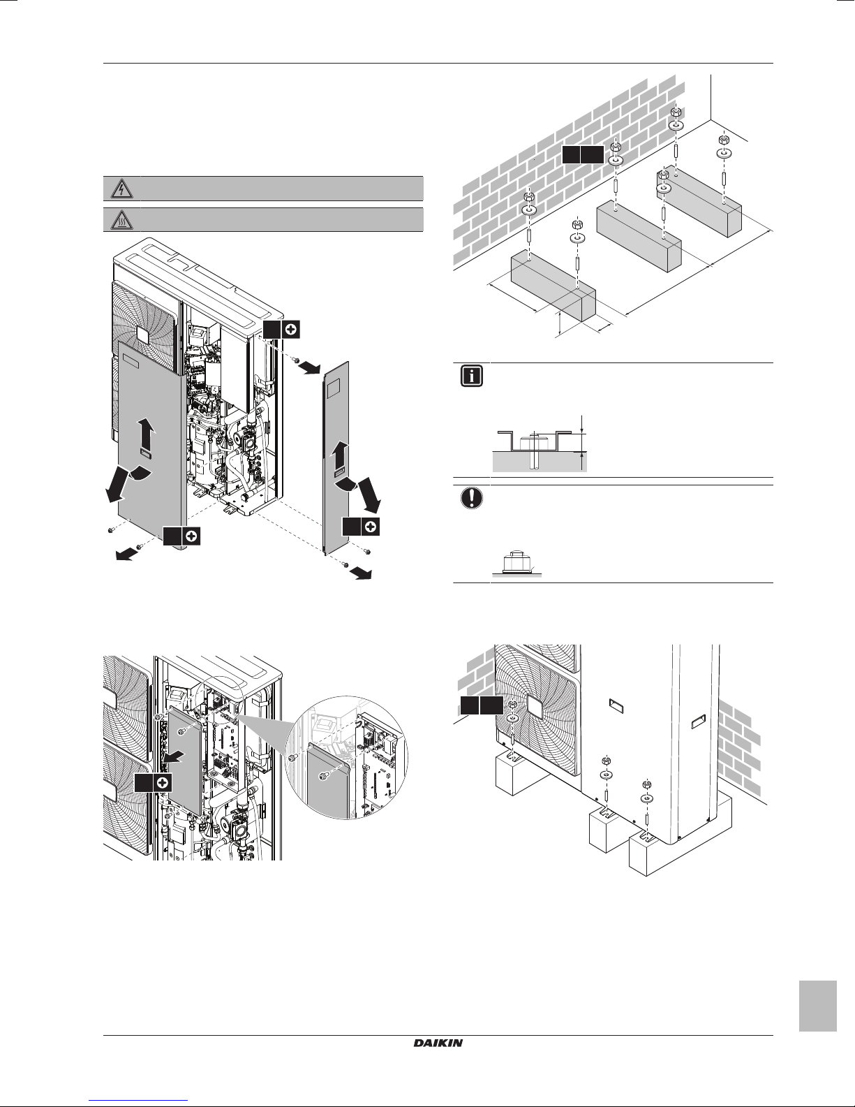
1 Open the outdoor unit.
2 Remove the accessories.
Installation manual
4
EBLQ+EDLQ011~016CAV3+W1
Daikin Altherma low temperature monobloc
4P522031-1 – 2018.01
ENERG
IJAY
IAIE
ENERG
IJAY
IAIE
1×
1× 1× 1× 1×
a b c d
2×2×
fe
g
a General safety precautions
FHL1
FHL2
FHL3
M1
T1 T3T2
M2 M3
f g
d
d
a eb c
b Addendum book for optional equipment
c Outdoor unit installation manual
d Operation manual
e Sealing ring for shut-off valve
f Shut-off valve
g Energy label
3 Preparation
3.1 Preparing the installation site
3.1.1 Installation site requirements of the
outdoor unit
Mind the spacing guidelines. See figure 1 on the inside of the front
cover.
The symbols can be interpreted as follows:
If the system contains a domestic hot water tank, meet the following
requirements:
domestic hot water tank 10m
3‑way valve 10m
The outdoor unit is designed for outdoor installation only, and for
ambient temperatures ranging 10~43°C in cooling mode, –25~25°C
in space heating mode, and –25~35°C in domestic hot water
operation mode.
3.2 Preparing water piping
A,C Left side and right side obstacles (walls/baffle plates)
B Suction side obstacle (wall/baffle plate)
D Discharge side obstacle (wall/baffle plate)
E Top side obstacle (roof)
a,b,c,d,e Minimum service space between the unit and obstacles A,
B, C, D and E
* If shut-off valves are NOT installed on the unit
† If shut-off valves are installed on the unit
eBMaximum distance between the unit and the edge of
obstacle E, in the direction of obstacle B
eDMaximum distance between the unit and the edge of
obstacle E, in the direction of obstacle D
HUHeight of the unit including the installation structure
HB,HDHeight of obstacles B and D
H Height of installation structure below the unit
INFORMATION
If shut-off valves are installed on the unit, provide a
minimum space of 400mm at the air inlet side. If shut‑off
valves are NOT installed on the unit, provide a minimum
space of 250mm.
Maximum allowable distance
between outdoor unit and …
NOTICE
In case of plastic pipes, make sure they are fully oxygen
diffusion tight according to DIN 4726. The diffusion of
oxygen into the piping can lead to excessive corrosion.
Distance
3 Preparation
3.2.1 To check the water volume and flow rate
The outdoor unit has an expansion vessel of 7litre with a factory-set
pre-pressure of 1bar.
See the installer reference guide for more information.
To make sure that the unit operates properly:
▪ You must check the minimum and maximum water volume.
▪ You might need to adjust the pre-pressure of the expansion
vessel.
Minimum water volume
If Then
The system contains a backup heater or
a DHW tank with recirculation pump
The system does NOT contain a backup
heater or a DHW tank with recirculation
pump
(a) The internal water volume of the outdoor unit NOT
included.
(b) If an EKHWP tank is installed, no recirculation pump is
required.
INFORMATION
In critical processes, or in rooms with a high heat load,
extra water might be required.
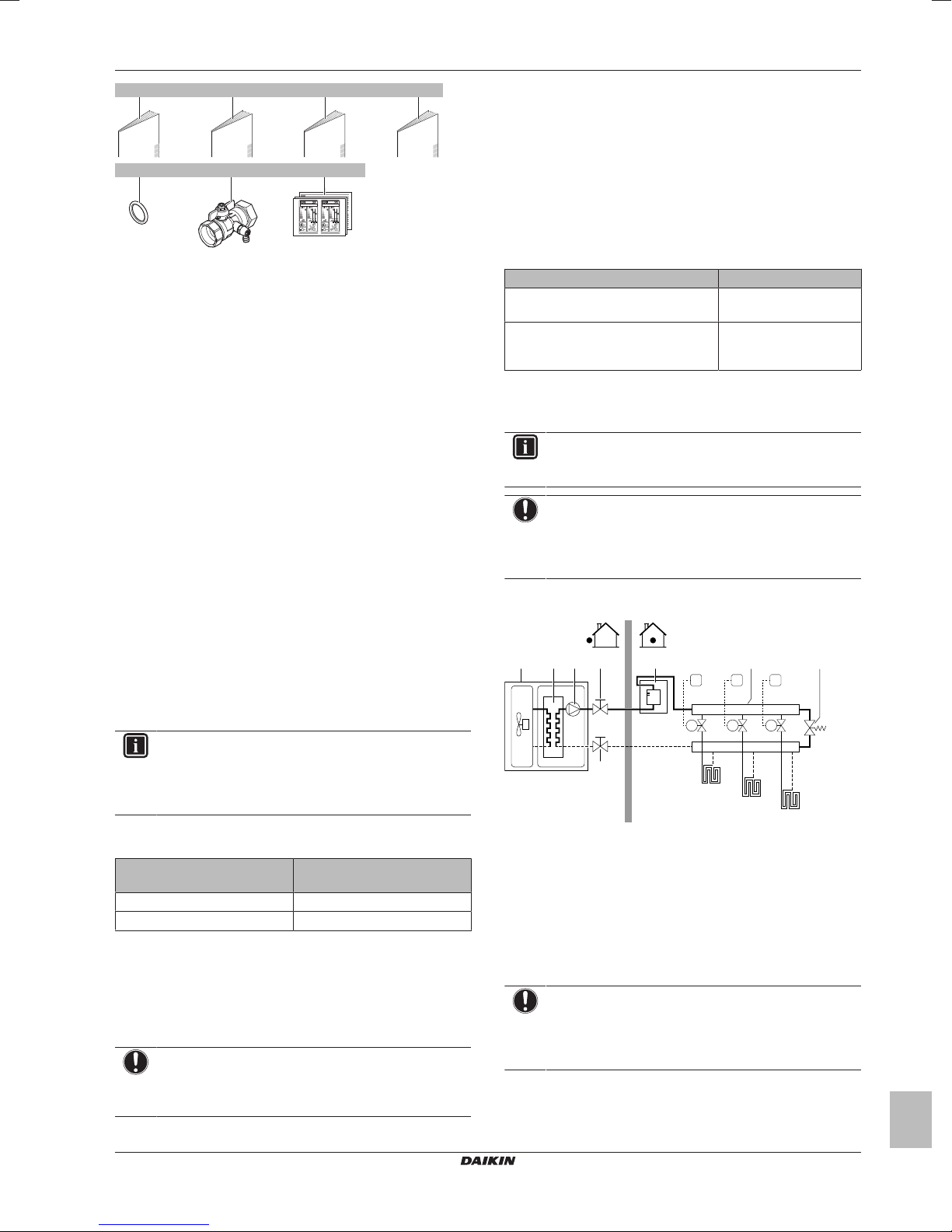
NOTICE
When circulation in each space heating/cooling loop is
controlled by remotely controlled valves, it is important that
the minimum water volume is guaranteed, even if all of the
valves are closed.
The following illustration shows a setup with remotely controlled
valves:
a Outdoor unit
b Heat exchanger
c Pump
d Shut‑off valve
e Backup heater kit (optional)
f Collector (field supply)
g By‑pass valve (field supply)
FHL1...3 Floor heating loop (field supply)
T1...3 Individual room thermostat (optional)
M1...3 Individual motorised valve to control loop FHL1...3 (field
supply)
Maximum water volume
NOTICE
The maximum water volume depends on whether glycol is
added to the water circuit. For more information on the
addition of glycol, refer to "4.3.3To protect the water circuit
against freezing"on page9.
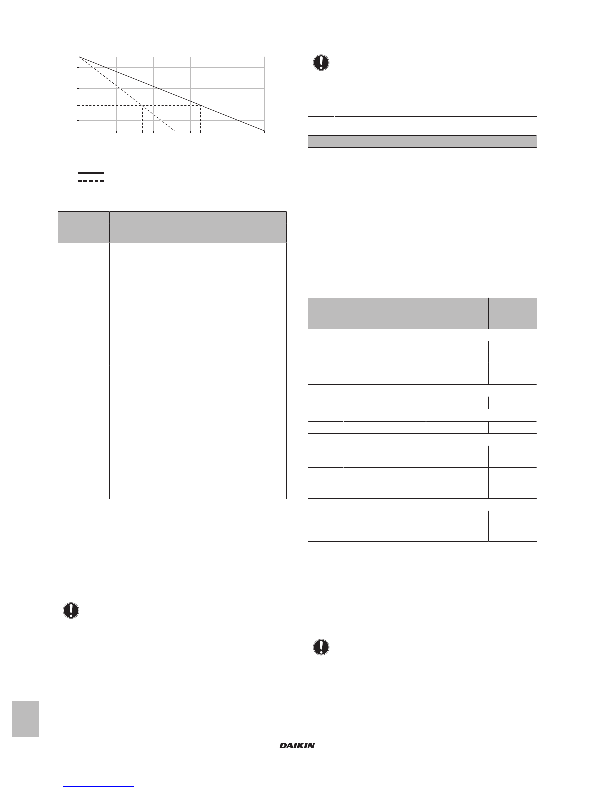
Use the following graph to determine the maximum water volume for
the calculated pre-pressure.
The minimum water
volume is 20l
The minimum water
volume is 80l
(a)
(a)(b)
EBLQ+EDLQ011~016CAV3+W1
Daikin Altherma low temperature monobloc
4P522031-1 – 2018.01
Installation manual
5
3 Preparation
20
2,4
2,1
1,8
1,5
1,2
0,9
1
0,6
0,3
70 120 170
150105 185
220
270
A
B
A Pre-pressure (bar)
B Maximum water volume (l)
Water
Water + glycol
Example: Maximum water volume and expansion vessel prepressure
Installation
height
difference
(a)
≤185/105l
≤7m No pre-pressure
adjustment is required.
>7m Do the following:
▪ Increase the pre-
pressure according to
the required
installation height
difference. The prepressure should
increase by 0.1 bar for
each metre above 7 m.
▪ Check if the water
volume does NOT
exceed the maximum
allowed water volume.
(a) This is the height difference (m) between the highest point
of the water circuit and the outdoor unit. If the outdoor unit
is at the highest point of the installation, the installation
height is 0m.
(b) The maximum water volume is 185l in case the circuit is
only filled with water, and 105l in case the circuit is filled
with water and glycol.
Minimum flow rate
Check that the minimum flow rate (required during defrost/backup
heater operation) in the installation is guaranteed in all conditions.
NOTICE
If glycol was added to the water circuit, and the
temperature of the water circuit is low, the flow rate will
NOT be displayed on the user interface. In this case, the
minimum flow rate can be checked by way of the pump
test (check that the user interface does NOT display error
7H).
Water volume
(b)
Do the following:
▪ Decrease the pre-
▪ Check if the water
The expansion vessel of
the outdoor unit is too
small for the installation.
In this case, it is
recommended to install
an extra vessel outside
the unit.
>185/105l
(b)
pressure according to
the required installation
height difference. The
pre-pressure should
decrease by 0.1 bar for
each metre below 7 m.
volume does NOT
exceed the maximum
allowed water volume.
NOTICE
When circulation in each or certain space heating loops is
controlled by remotely controlled valves, it is important that
the minimum flow rate is guaranteed, even if all valves are
closed. In case the minimum flow rate cannot be reached,
a flow error 7H will be generated (no heating or operation).
See the installer reference guide for more information.
Minimum required flow rate
The system contains a backup heater / DHW tank
15l/min
with recirculation pump / glycol
The system does NOT contain a backup heater /
DHW tank with recirculation pump
(a) If an EKHWP tank is installed, no recirculation pump is
required.
(a)
/ glycol
20l/min
See the recommended procedure as described in "6.2 Checklist
during commissioning"on page21.
3.3 Preparing electrical wiring
3.3.1 Overview of electrical connections for
external and internal actuators
Item Description Wires Maximum
Outdoor unit power supply
1 Power supply for
2+GND
outdoor unit
2 Normal kWh rate power
2 6.3A
supply
User interface
3 User interface 2
Optional equipment
4 Remote outdoor sensor 2
Field-supplied components
5 Domestic hot water
2
pump
6 Space heating/cooling
2
operation control (or
shut‑off valve)
Interconnection cable
7 Interconnection cable
2
between outdoor unit
and control box
(a) Refer to name plate on outdoor unit.
(b) Cable section 0.75mm² till 1.25mm²; maximum length:
500m. Applicable for both single user interface and dual
user interface connection.
(c) Minimum cable section 0.75mm².
(d) Cable section 0.75mm² till 1.25mm²; maximum length:
20m.
(e) If valve kit EKMBHBP1 is part of the system, then the
required cable section is 0.75mm². If valve kit EKMBHBP1
is NOT part of the system, then the minimum required
cable section is 0.75mm².
NOTICE
More technical specifications of the different connections
are indicated on the inside of the outdoor unit.
running
current
(a)
(b)
(c)
(c)
(e)
(d)
Installation manual
6
EBLQ+EDLQ011~016CAV3+W1
Daikin Altherma low temperature monobloc
4P522031-1 – 2018.01
4 Installation
1×
2×
2×
6
5
1
3
4
2
8
9
7
3×
≥150
620
350
(345-355)
a
(mm)
261.5
6× M12
20
a
6× M12
4.1 Opening the units
4.1.1 To open the outdoor unit
DANGER: RISK OF ELECTROCUTION
DANGER: RISK OF BURNING
4 Installation
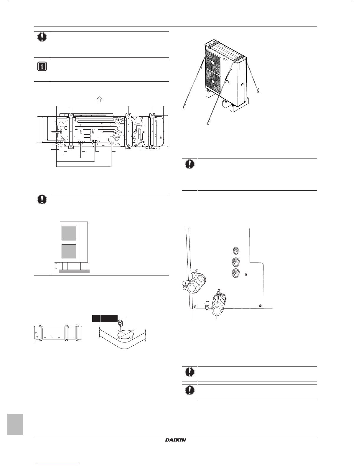
a Make sure not to cover the drain holes.
INFORMATION
The recommended height of the upper protruding part of
the bolts is 20mm.
4.1.2 To open the switch box cover of the
outdoor unit
4.2 Mounting the outdoor unit
4.2.1 To provide the installation structure
Prepare 6 sets of anchor bolts, nuts and washers (field supply) as
follows:
EBLQ+EDLQ011~016CAV3+W1
Daikin Altherma low temperature monobloc
4P522031-1 – 2018.01
NOTICE
Fix the outdoor unit to the foundation bolts using nuts with
resin washers (a). If the coating on the fastening area is
stripped off, the nuts rust easily.
4.2.2 To install the outdoor unit
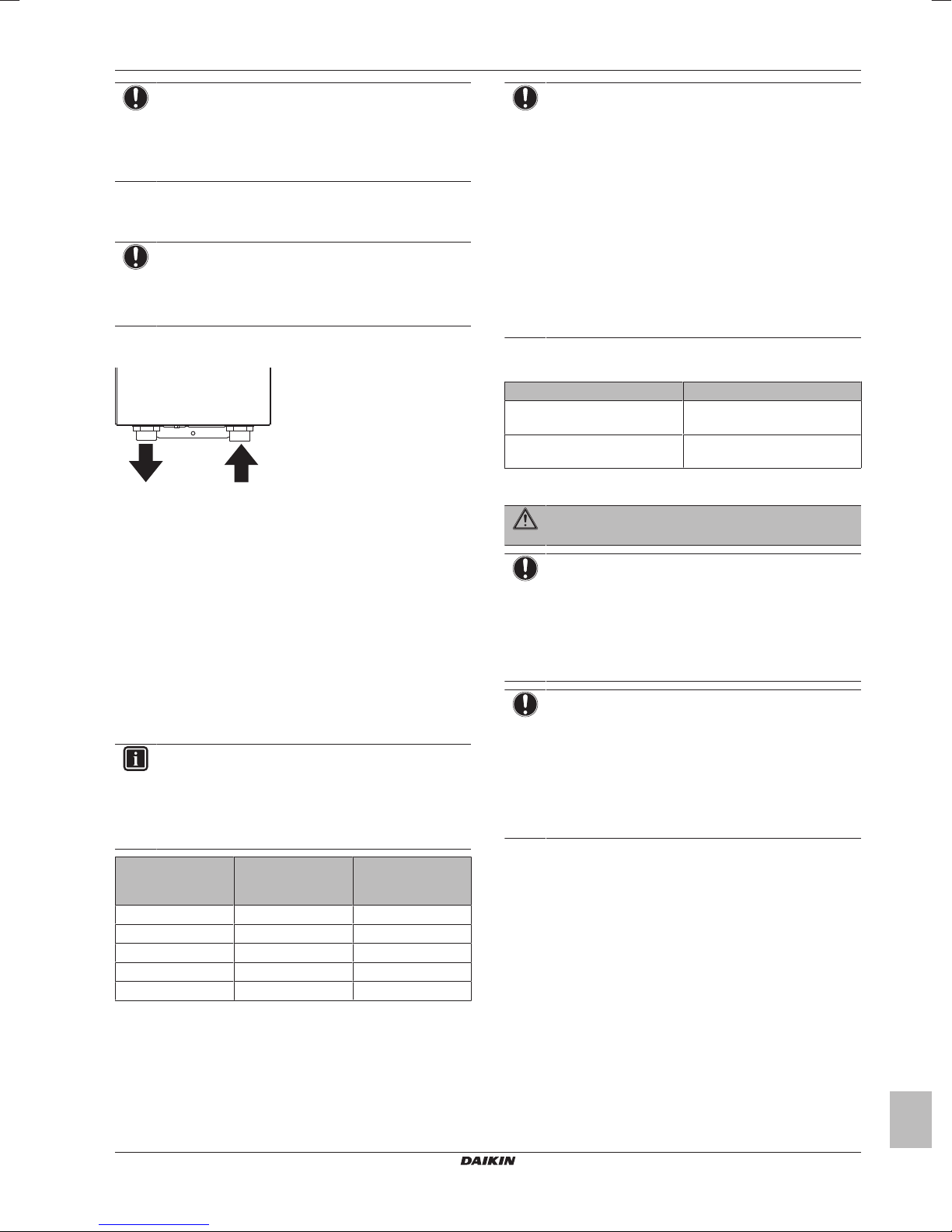
4.2.3 To provide drainage
Make sure that condensate can be evacuated properly. When the
unit is in cooling mode, condensate may also form in the hydro part.
When providing drainage, therefore make sure to cover the entire
unit.
Installation manual
7
4 Installation
160 620 261.5 119
161
260
285
279
345
595
416
262
38
71
C
D
E
DDDD
A
B
≥150 mm
b
a b
4× Ø6 mm
a b
NOTICE
If the unit is installed in a cold climate, take adequate
measures so that the evacuated condensate CANNOT
freeze.
INFORMATION
If necessary, you can use a drain plug kit (field supply) to
prevent drain water from dripping.
Drain holes (dimensions in mm)
A Discharge side
B Distance between anchor points
C Bottom frame
D Drain holes
E Knockout hole for snow
NOTICE
If drain holes of the outdoor unit are covered by a mounting
base or by floor surface, raise the unit to provide a free
space of more than 150mm under the outdoor unit.
4 Attach the ends of the cables and tighten them.
4.3 Connecting the water piping
4.3.1 To connect the water piping
NOTICE
Do NOT use excessive force when connecting the piping.
Deformation of the piping can cause malfunctioning of the
unit. Make sure that the tightening torque does NOT
exceed 30N•m.
To facilitate service and maintenance, 2 shut-off valves are provided.
Mount the valves on the space heating water inlet and space heating
water outlet. Mind their position: the integrated drain valves will only
drain the side of the circuit on which they are located. To be able to
only drain the unit, make sure the drain valves are positioned
between the shut‑off valves and the unit.
Snow
In regions with snowfall, snow might build up and freeze between the
heat exchanger and the external plate. This might decrease the
operating efficiency. To prevent this:
1 Drill (a, 4×) and remove the knockout hole (b).
2 Remove the burrs, and paint the edges and areas around the
edges using repair paint to prevent rusting.
4.2.4 To prevent the outdoor unit from falling
over
In case the unit is installed in places where strong wind can tilt the
unit, take following measure:
1 Prepare 2 cables as indicated in the following illustration (field
supply).
2 Place the 2 cables over the outdoor unit.
3 Insert a rubber sheet between the cables and the outdoor unit
to prevent the cables from scratching the paint (field supply).
Installation manual
8
a Water inlet
b Water outlet
1 Screw the outdoor unit nuts on the shut-off valves.
2 Connect the field piping on the shut-off valves.
3 In case of connection with the optional domestic hot water tank,
see the installation manual of the domestic hot water tank.
NOTICE
Install a manometer in the system.
NOTICE
Install air purge valves at all local high points.
EBLQ+EDLQ011~016CAV3+W1
Daikin Altherma low temperature monobloc
4P522031-1 – 2018.01
4 Installation
b
a
NOTICE
In case an optional domestic hot water tank is installed: A
pressure relief valve (field supply) with an opening
pressure of maximum 10 bar must be installed on the
domestic cold water inlet connection in accordance with
the applicable legislation.
4.3.2 To connect the water piping to the backup
heater
NOTICE
Do NOT use excessive force when connecting the piping.
Deformation of the piping can cause malfunctioning of the
unit. Make sure that the tightening torque does NOT
exceed 30N•m.
1 Connect the water piping (field supply) to the water in- and
outlet of the backup heater.
a Water inlet
b Water outlet
4.3.3 To protect the water circuit against
freezing
Frost can damage the system. To prevent the hydraulic components
from freezing, the software is equipped with special frost protection
functions, that include the activation of pump, internal heaters, and/
or backup heater operation in case of low temperatures.
However, in case of a power failure, these functions cannot
guarantee protection. It is therefore recommended to add glycol to
the water circuit. The required concentration depends on the lowest
expected outdoor temperature, and on whether you want to protect
the system from bursting or from freezing. To prevent the system
from freezing, more glycol is required. Add glycol according to the
table below.
INFORMATION
▪ Protection against bursting: the glycol will prevent the
piping from bursting, but NOT the liquid inside the
piping from freezing.
▪ Protection against freezing: the glycol will prevent the
liquid inside the piping from freezing.
NOTICE
▪ The required concentration might differ depending on
the type of glycol. ALWAYS compare the requirements
from the table above with the specifications provided by
the glycol manufacturer. If necessary, meet the
requirements set by the glycol manufacturer.
▪ The added concentration of glycol should NEVER
exceed 35%.
▪ If the liquid in the system is frozen, the pump will NOT
be able to start. Mind that if you only prevent the
system from bursting, the liquid inside might still freeze.
▪ In case of a power supply failure or pump failure, and
NO glycol was added to the system, drain the system.
▪ When water is at standstill inside the system, the
system is very likely to freeze and get damaged.
The types of glycol that can be used depend on whether the system
contains a domestic hot water tank:
If… Then…
The system contains a domestic
hot water tank
The system does NOT contain a
domestic hot water tank
(a) Propylene glycol, including the necessary inhibitors,
classified as CategoryIII according to EN1717.
WARNING
Ethylene glycol is toxic.
NOTICE
Glycol absorbs water from its environment. Therefore do
NOT add glycol that has been exposed to air. Leaving the
cap off the glycol container causes the concentration of
water to increase. The glycol concentration is then lower
than assumed. As a result, the hydraulic components
might freeze up after all. Take preventive actions to ensure
a minimal exposure of the glycol to air.
NOTICE
▪ If overpressure occurs, the system will release some of
the liquid through the pressure relief valve. If glycol was
added to the system, take adequate measures so as to
safely recover it.
▪ In any case, make sure that the flexible hose of the
pressure relief valve is ALWAYS free to release
pressure. Prevent water from staying and/or freezing
up inside the hose.
Only use propylene glycol
You can use either propylene
(a)
glycol
or ethylene glycol
(a)
Lowest expected
outdoor
temperature
–5°C 10% 15%
–10°C 15% 25%
–15°C 20% 35%
–20°C 25% —
–25°C 30% —
EBLQ+EDLQ011~016CAV3+W1
Daikin Altherma low temperature monobloc
4P522031-1 – 2018.01
Prevent from
bursting
Prevent from
freezing
Installation manual
9
 Loading...