

Daikin DX17VSS181AA, DX17VSS series, DX17VSS241AA, DX17VSS301AA, DX17VSS361AA Installation Instructions Manual
AIR CONDITIONER
English
DX17VSS AIR CONDITIONING
INSTALLATION & SERVICE REFERENCE
Index
ImportAnt sAfety InstruCtIons ............................................. 1
shIppIng InspeCtIon .............................................................. 1
Codes & regulAtIons .......................................................... 2
feAtures..............................................................................2
preCAutIons for seleCtIng A loCAtIon ................................. 2
preCAutIons for InstAllAtIon ............................................... 3
InstAllAtIon CleArAnCes ...................................................... 3
rooftop InstAllAtIons .........................................................3
sAfety ConsIderAtIons.........................................................4
refrIgerAnt lInes ............................................................... 6
refrIgerAnt lIne ConneCtIons ............................................. 8
leAK testIng (nItrogen or nItrogen-trACed) ......................8
system stArt-up proCedure ................................................ 8
stArt-up proCedure detAIl .................................................. 9
eleCtrICAl ConneCtIons ...................................................... 9
AIr CondItIoner AdvAnCed feAture menu ........................... 30
wIrIng dIAgrAm ................................................................33
CApACItor .......................................................................... 34
troubleshootIng ............................................................... 36
settIng the mode dIsplAy .................................................. 41
7-segment dIsplAy ............................................................. 47
stArt up CheCKlIst ........................................................... 51
INSTALLATION INSTRUCTIONS
imPoRtant saFety instRuCtions
The following symbols and labels are used throughout this
manual to indicate immediate or potential safety hazards. It is
the owner’s and installer’s responsibility to read and comply
with all safety information and instructions accompanying
these symbols. Failure to heed safety information increases
the risk of personal injury, property damage, and/or product
damage.
WARNING
HIGH VOLTAGE !
dIsConneCt All power before servICIng.
m
ultIple power sourCes mAy be present. fAIlure
to do so mAy CAuse property dAmAge, personAl
Injury or deAth.
WARNING
only personnel thAt hAve been trAIned to InstAll, Adjust, ser-
vICe or repAIr (hereInAfter, “servICe”) the equIpment speCIfIed
In thIs mAnuAl should servICe the equIpment. the mAnufACturer
wIll not be responsIble for Any Injury or property dAmAge ArIs-
Ing from Improper servICe or servICe proCedures. If you servICe
thIs unIt, you Assume responsIbIlIty for Any Injury or property
dAmAge whICh mAy result. In AddItIon, In jurIsdICtIons thAt re-
quIre one or more lICenses to servICe the equIpment speCIfIed In
thIs mAnuAl, only lICensed personnel should servICe the equIp-
ment. Improper InstAllAtIon, Adjustment, servICIng or repAIr of
the equIpment speCIfIed In thIs mAnuAl, or AttemptIng to InstAll,
Adjust, servICe or repAIr the equIpment speCIfIed In thIs mAnuAl
wIthout proper trAInIng mAy result In produCt dAmAge, property
dAmAge, personAl Injury or deAth.
shiPPing insPeCtion
Always keep the unit upright; laying the unit on its side or top
may cause equipment damage. Shipping damage, and subsequent investigation is the responsibility of the carrier. Verify
the model number, speci cations, electrical characteristics,
and accessories are correct prior to installation. The distributor
or manufacturer will not accept claims from dealers for transportation damage or installation of incorrectly shipped units.
Codes & Regulations
This product is designed and manufactured to comply with
national codes. Installation in accordance with such codes
and/or prevailing local codes/regulations is the responsibility
of the installer. The manufacturer assumes no responsibility
for equipment installed in violation of any codes or regulations.
Rated performance is achieved after 72 hours of operation.
Rated performance is delivered at the specied airow. See
outdoor unit specication sheet for split system models or
product specication sheet for packaged and light commercial
models. Specication sheets can be found at www.daikin-
comfort.com for Daikin products. Within the website, please
select the products menu and then select the submenu for
the type of product to be installed, such as air conditioners,
to access a list of product pages that each contain links to
that model’s specication sheet.
The United States Environmental Protection Agency
(EPA) has issued various regulations regarding the introduction and disposal of refrigerants. Failure to follow
these regulations may harm the environment and can
lead to the imposition of substantial nes.
Should you have any questions please contact our local EPA
ofce.
If replacing one of the component of the system, the system
must be manufacturer approved and Air Conditioning, Heating
and Refrigeration Institute (AHRI) matched.
NOTE: The installation of an inverter air conditioner with
unmatched system units will not allow for proper operation.
NOTICE
Inverter A/C models CAn only be mAtChed wIth A CApeA** And
Chpe** A-CoIl. dAmAge resultIng from operAtIon wIth Any other
CombInAtIon Is not Covered by our wArrAntIes.
Outdoor inverter units are approved for operation above 0°F
in cooling mode with no additional kit necessary.
Damage resulting from operation of the unit in a structure
that is not complete (either as part of new construction or
renovation) is not covered by our warranties.
FeatuRes
This air conditioner is part of a system that uses inverter
technology to more efciently remove heat and achieve the
target cooling setting. System may ONLY be installed using
a ComfortNet™ thermostat with model number CTK04AE or
newer as part of the digital communicating system. The ComfortNet system reduces the number of required thermostat
wires, provides additional setup features and enhanced active
diagnostics. Due to components using inverter technology, the
air conditioner will not function properly if used with a CTK03,
02 or 01 ComfortNet thermostat.
PReCautions FoR seleCting a loCation
1. Choose a place solid enough to bear the weight and
vibration of the unit, where the operating sound will
not be amplied.
2. Choose a location where the hot air discharged
from the unit or the operating sound will not cause a
nuisance to the neighbours of the user.
3. Avoid places near a bedroom and the like, so that the
operating sound will cause no trouble.
4. There must be sufcient spaces for carrying the unit
into and out of the site.
5. There must be sufcient space for air passage and no
obstructions around the air inlet and the air outlet.
6. The site must be free from the possibility of ammable
gas leakage in a nearby place.
7. Do not install the air conditioner in the following
locations:
(a) Where a mineral oil mist or oil spray or vapor is produced,
for example, in a kitchen.
Plastic parts may deteriorate and fall off and thus may
result in water leakage.
(b) Where corrosive gas, such as sulfurous acid gas, is pro-
duced.
Corroding copper pipes or soldered parts may result in
refrigerant leakage.
(c) Near machinery emitting electromagnetic waves.
Electromagnetic waves may disturb the operation of the
control system and cause the unit to malfunction.
(d) Where ammable gas may leak, where there is carbon -
ber, or ignitable dust suspension in the air, or where vola-
tile ammables such as thinner or gasoline are handled.
Operating the unit in such conditions may result in a re.
NOTE: Cannot be installed suspended from ceiling or stacked.
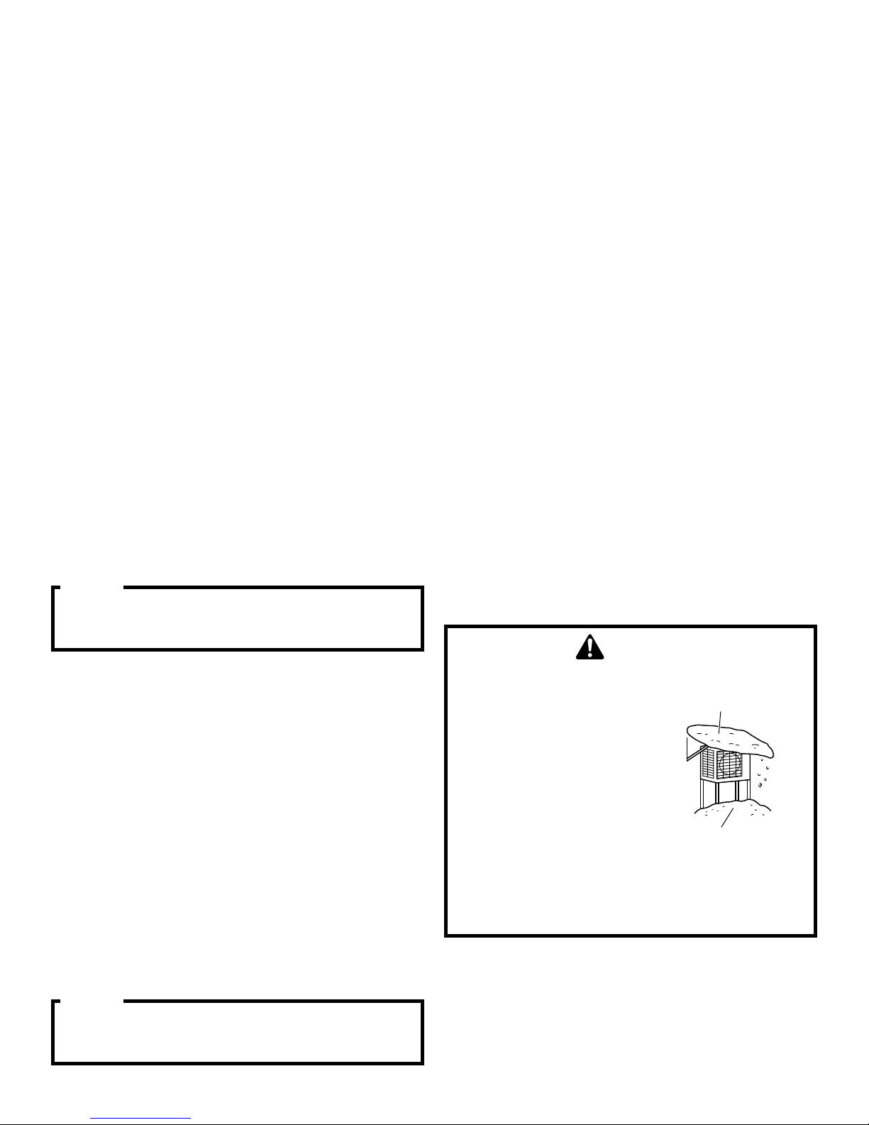
CAUTION
when operAtIng the AIr CondItIoner In
A low outdoor AmbIent temperAture,
be sure to follow the InstruCtIons
desCrIbed below.
•to prevent exposure to wInd, InstAll
the outdoor unIt wIth Its suCtIon
sIde fACIng the wAll.
•never InstAll the outdoor unIt At A
sIte where the suCtIon sIde mAy be
exposed dIreCtly to wInd.
•to prevent exposure to wInd, It Is
reCommended to InstAll A bAffle
plAte on the AIr dIsChArge sIde of
the outdoor unIt.
•In heAvy snowfAll AreAs, seleCt An
InstAllAtIon sIte where the snow
wIll not AffeCt the unIt.
• Construct a large
canopy.
• Construct a pedestal.
Install the unit high
enough off the ground
to prevent burying in
snow.
NOTICE
should use CtK04Ae or newer.
n
ot Approved for use wIth A CtK01, CtK02, CtK03,
CtK04Ad or older.
2
English
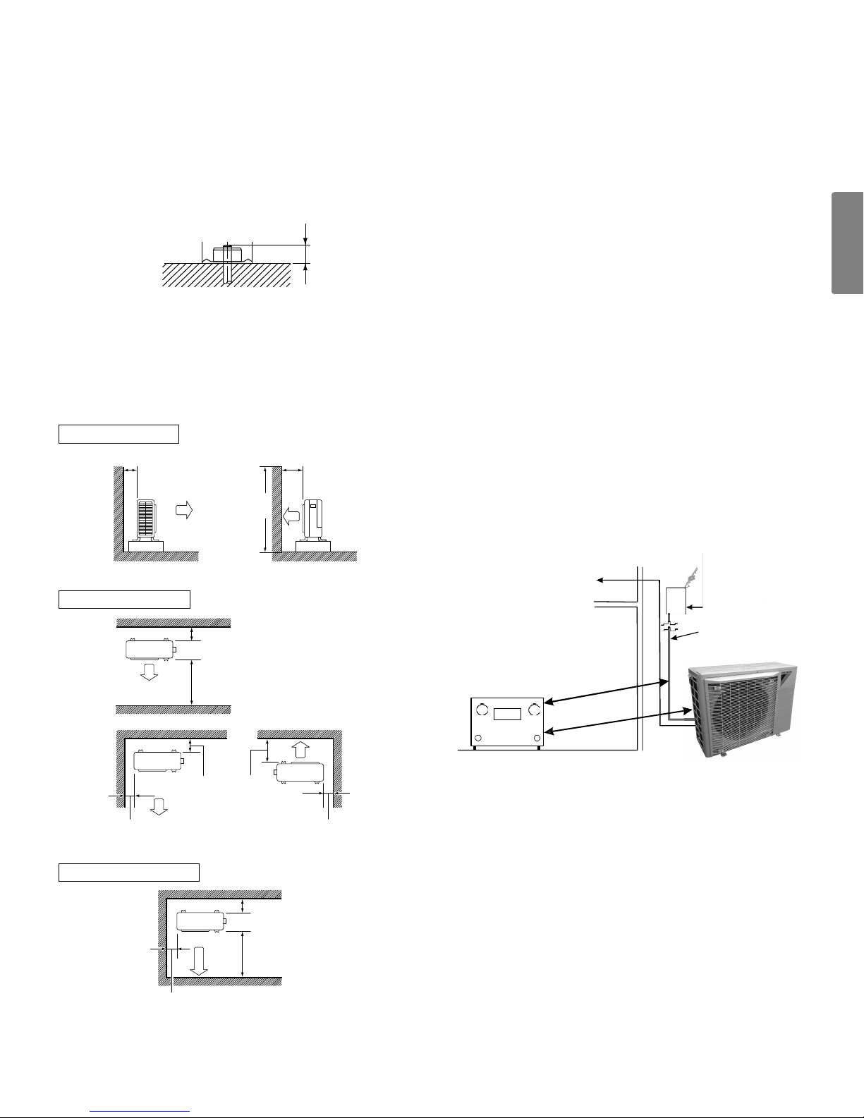
PReCautions FoR installation
• Check the strength and level of the installation ground
so that the unit will not cause any operating vibration or
noise after installed.
• Fix the unit securely by means of the foundation bolts.
(Prepare 4 sets of 3/8” or 7/16” foundation bolts, nuts and
washers; all separately available.)
• It is best to screw in the foundation bolts until their ends
are 1 inch from the foundation surface.
At ground oor level, the unit must be on a solid, level foun-
dation that will not shift or settle. To reduce the possibility
of sound transmission, the foundation slab should not be in
contact with or be an integral part of the building foundation.
Care should be taken to ensure the unit is installed away
from noise sensitive locations such as bedrooms, windows
and outdoor living areas. Ensure the foundation is suf cient
to support the unit. A concrete slab raised above ground level
provides a suitable base.
1”
installation CleaRanCes
• Where a wall or other obstacle is in the path of the out-
door unit’s intake or exhaust air ow, follow the installation
space requirements below.
• For any of the below installation patterns, the wall height
on the outlet side should be 47” or less.
Wall facing one side
More than 4” More than 14”
Direction
of air
Walls facing two sides
47” or
less
Side view
More
than 4”
RooFtoP installations
If it is necessary to install this unit on a roof structure, ensure
the roof structure can support the weight and that proper
consideration is given to the weather-tight integrity of the roof.
Since the unit can vibrate during operation, sound vibration
transmission should be considered when installing the unit.
Vibration absorbing pads or springs can be installed between
the air conditioner unit legs or frame and the roof mounting
assembly to reduce noise vibration.
eleCtrICAl noIse
The unit should be well grounded so that potential effects of
electrical noise from the inverter to surrounding equipment
can be minimized.
When selecting an installation location, keep suf cient dis-
tance from the air conditioner unit and wiring to radios, per-
sonal computers, stereos, uorescent lamp, etc., as shown
in the following gure.
Circuit
To Indoor Unit and
Thermostat
Breaker
High voltage
power cable
More
than 14”
More
than 4”
More than 2” More than 2”
Walls facing three sides
More than 2”
More
than 14”
Top view
More than 4”
More than 14”
Top view
This unit can be located at ground oor level or on at roofs.
unit: inch
Radio, TV
(In.)
Placement to Minimize Electronic Noise
60” or more
60” or more
3
saFety ConsideRations
Read these Safety considerations for Installation carefully
before installing an air conditioner. After completing the installation, make sure that the unit operates properly during the
system start-up operation.
Instruct the customer on how to operate and maintain the unit.
Inform customers that they should store this Installation
Manual for future reference.
Always use a licensed installer or contractor to install this
product.
Improper installation can result in water or refrigerant leakage,
electrical shock, re, or explosion.
Meanings of WARNING, CAUTION, and NOTICE
Symbols:
WARNING .......
CAUTION ........
NOTICE .........
Indicates imminently or potentially
hazardous situation which, if not
avoided, will result in death or serious injury.
Indicates a potentially hazardous
situation which, if not avoided, may
result in minor or moderate injury. It
may also be used to alert against
unsafe practices.
Indicates situations that may result
in equipment or property-damage
accidents only.
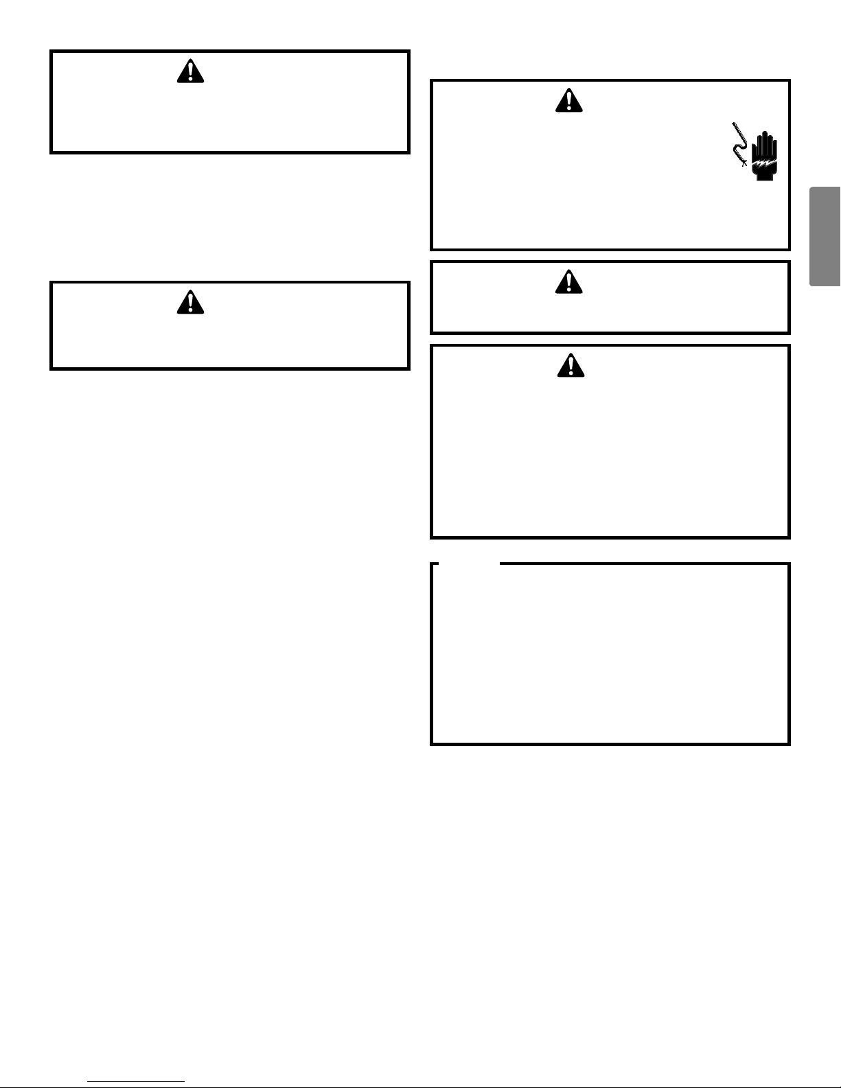
WARNING
refrIgerAnts Are heAvIer thAn AIr. they CAn “push out” the
oxygen In your lungs or In Any enClosed spACe. to AvoId pos-
sIble dIffICulty In breAthIng or deAth:
•never purge refrIgerAnt Into An enClosed room or spACe. by
lAw, All refrIgerAnts must be reClAImed.
•If An Indoor leAK Is suspeCted, thoroughly ventIlAte the AreA
before begInnIng worK.
•lIquId refrIgerAnt CAn be very Cold. to AvoId possIble frost
bIte or blIndness, AvoId ContACt And weAr gloves And goggles.
I
f lIquId refrIgerAnt does ContACt your sKIn or eyes, seeK
medICAl help ImmedIAtely.
•If refrIgerAnt gAs leAKs durIng InstAllAtIon, ventIlAte the
AreA ImmedIAtely. refrIgerAnt gAs wIll result In produCIng
toxIC gAs If It Comes Into ContACt wIth fIre. exposure to thIs
gAs wIll result In severe Injury or deAth.
•After CompletIng the InstAllAtIon worK, CheCK thAt the re-
frIgerAnt gAs does not leAK throughout the system.
•do not InstAll unIt In An AreA where flAmmAble mAterIAls Are
present due to rIsK of explosIons thAt wIll result In serIous
Injury or deAth.
•when InstAllIng the unIt In A smAll room, tAKe meAsures to
Keep the refrIgerAnt ConCentrAtIon from exCeedIng AllowAble
sAfety lImIts. exCessIve refrIgerAnt leAKs, In the event of An
ACCIdent In A Closed AmbIent spACe, Could result In oxygen
defICIenCy.
•AlwAys follow epA regulAtIons. never burn refrIgerAnt, As
p
oIsonous gAs wIll be produCed.
While these items will not cover every conceivable situation,
they should serve as a useful guide.
WARNING
to AvoId possIble Injury, explosIon or deAth, prACtICe sAfe
hAndlIng of refrIgerAnts.
WARNING
to AvoId possIble explosIon, use only returnAble (not dIspos-
Able) servICe CylInders when removIng refrIgerAnt from A
system.
•ensure the CylInder Is free of dAmAge whICh Could leAd to A
leAK or explosIon.
•ensure the hydrostAtIC test dAte does not exCeed 5 yeArs.
•ensure the pressure rAtIng meets or exCeeds 400 psIg.
w
hen In doubt, do not use CylInder.
4
English
WARNING
to AvoId possIble explosIon:
•never Apply flAme or steAm to A refrIgerAnt CylInder. If you
must heAt A CylInder for fAster ChArgIng, pArtIAlly Immerse It
In wArm wAter.
•never fIll A CylInder more thAn 80% full of lIquId refrIger-
Ant.
•never Add AnythIng other thAn r-410A to A returnAble r410A
CylInder. the servICe equIpment used must be lIsted or
CertIfIed for the type of refrIgerAnt use.
•store CylInders In A Cool, dry plACe. never use A CylInder As
A plAtform or A roller.
CAUTION
•refrIgerAnt r410A In the system must be Kept CleAn, dry, And
tIght.
(a) CleAn And dry - foreIgn mAterIAls (InCludIng mInerAl oIls
suCh As sunIso o Il or moIst ure) should be prev ented
from gettIng Into the system.
(b) tI ght - r410A does not ContAIn A ny ChlorIne, does not
destroy the ozone lAyer, And does not reduCe the eArth’s
proteC tIon AgAIn hArm ful u ltrAvIolet rAdIAtIon. r410A
CAn ContrIbute to the greenhouse effeCt If It Is releAsed.
t
herefore tAKe proper meAsures to CheCK for the tIght-
ness of the refrIgerAnt pIpIng InstAllAtIon. reAd the ChAp-
ter refrIgerAnt pIpIng And follow the proCedures.
•sInCe r410A Is A blend, the requIred AddItIonAl refrIger-
Ant must be ChArged In Its lIquId stAte. If the refrIgerAnt Is
ChArged In A stAte of gAs, Its ComposItIon CAn ChAnge And the
system wIll not worK properly.
WARNING
•do not ground unIts to wAter pIpes, suCtIon lIne, telephone
wIres, or lIghtnIng rods As InComplete groundIng wIll result A
severe shoCK hAzArd resultIng In severe Injury or deAth. Ad-
dItIonAlly, groundIng to gAs pIpes wIll result A gAs leAK And
potentIAl explosIon resultIng In severe Injury or deAth.
•sAfely dIspose All pACKIng And trAnsportAtIon mAterIAls In AC-
CordAnCe wIth federAl/stAte/loCAl lAws or ordInAnCes. pACK-
Ing mAterIAls suCh As nAIls And other metAl or wood pArts,
InCludIng plAstIC pACKIng mAterIAls used for trAnsportAtIon
wIll result In InjurIes or deAth by suffoCAtIon.
•only quAlIfIed personnel must CArry out the InstAllAtIon
worK. InstAllAtIon must be done In ACCordAnCe wIth thIs
InstAllAtIon mAnuAl. Improper InstAllAtIon Could result In
wAter leAKAge, eleCtrIC shoCK, or fIre.
•use only speCIfIed ACCessorIes And pArts for InstAllAtIon
worK. fAIlure to use speCIfIed pArts Could result In wAter
leAKAge, eleCtrIC shoCKs, fIre, or the unIt fAllIng.
•InstAll the AIr CondItIoner on A foundAtIon strong enough
thAt It CAn wIthstAnd the weIght of the unIt. A foundAtIon of
InsuffICIent strength Could result In the unIt fAllIng And CAus-
Ing InjurIes.
•tAKe Into ACCount strong wInds, typhoons, or eArthquAKes
when InstAllIng. Improper InstAllAtIon Could result In the unIt
fAllIng And CAusIng ACCIdents.
•mAKe sure thAt A sepArAte power supply CIrCuIt Is provIded
for thIs unIt And thAt All eleCtrICAl worK Is CArrIed out
by quAlIfIed personnel ACCordIng to loCAl, stAte And nA-
tIonAl regulAtIons. An InsuffICIent power supply CApACIty or
Improper eleCtrICAl ConstruCtIon Could result In eleCtrIC
shoCKs or fIre.
•mAKe sure thAt All wIrIng Is seCured, thAt speCIfIed wIres Are
used, And thAt no externAl forCes ACt on the termInAl Con-
neCtIons or wIres. Improper ConneCtIons or InstAllAtIon Could
result In fIre.
•when wIrIng, posItIon the wIres so thAt the sIde plAte whICh
Covers termInAl bloCK of power CAble CAn be seCurely fAs-
tened. Improper posItIonIng of the sIde plAte Could result In
eleCtrIC shoCKs, fIre, or the termInAls overheAtIng.
•thIs equIpment CAn be InstAlled wIth A ground-fAult CIrCuIt
I
nterrupter (gfCI). Although thIs Is A reCognIzed meAsure
for AddItIonAl proteCtIon, wIth the groundIng system In north
A
merICA, A dedICAted gfCI Is not neCessAry.
•do not ChAnge the settIng of the proteCtIon devICes. If the
pressure swItCh, thermAl swItCh, or other proteCtIon devICe
Is shorted And operAted forCIbly, or pArts other thAn those
speCIfIed by dAIKIn Are used, fIre or explosIon Could result.
5
CAUTION
•do not touCh the swItCh wIth wet fIngers. touChIng A swItCh
wIth wet fIngers mAy result In eleCtrIC shoCK.
•do not Allow ChIldren to plAy on or Around the unIt or It mAy
result In Injury.
•the heAt exChAnger fIns Are shArp enough to Cut, And mAy
result In Injury If Improperly used. to AvoId Injury weAr glove
or Cover the fIns when worKIng Around them.
•do not touCh the refrIgerAnt pIpes durIng And ImmedIAtely
After operAtIon As the refrIgerAnt pIpes mAy be hot or Cold,
dependIng on the CondItIon of the refrIgerAnt flowIng through
the refrIgerAnt pIpIng, Compressor, And other refrIgerAnt
CyCle pArts. It mAy result In your hAnds gettIng burns or
frostbIte If you touCh the refrIgerAnt pIpes. to AvoId Injury,
gIve the pIpes tIme to return to normAl temperAture or, If you
must touCh them, be sure to weAr proper gloves.
•InsulAte suCtIon pIpIng to prevent CondensAtIon.
•be CAreful when trAnsportIng the produCt.
•tAKe AdequAte meAsures to prevent the outdoor unIt from
beIng used As A shelter by smAll AnImAls. smAll AnImAls mAK-
Ing ContACt wIth eleCtrICAl pArts mAy result In mAlfunCtIons,
smoKe, or fIre. InstruCt the Customer to Keep the AreA Around
the unIt CleAn.
NOTICE
•If the ConventIonAl refrIgerAnt And refrIgerAtor oIl Are mIxed
In r410A, the refrIgerAnt result In deterIorAtIon.
•thIs AIr CondItIoner Is An ApplIAnCe thAt should not be ACCes-
sIble to the generAl publIC.
•As desIgn pressure Is 450 psI (3.1 mpA), the wAll thICKness
of fIeld-InstAlled pIpes should be seleCted In ACCordAnCe wIth
the relevAnt loCAl, stAte, And nAtIonAl regulAtIons.
damping material. Avoid suspending refrigerant tubing from
joists and studs with rigid wire or straps that would come in
contact with the tubing. Use an insulated or suspension type
hanger. Keep both lines separate and always insulate the
suction line.
Insulation is necessary to prevent condensation from forming
and dropping from the suction line. Insulation tube with 3/8”
min. wall thickness is recommended. In severe conditions
(likely to exceed 86°F and a relative humidity of 80%) 1/2”
insulation may be required. Insulation must be installed in a
manner which protects tubing and connections from damage
and contamination.
Please use a HVAC ushing solvent to clean lineset of any
oil or debris from the existing system.
NOTE: If changing refrigerant, the indoor coil and metering
device must be replaced.
Cond
Unit
Tons
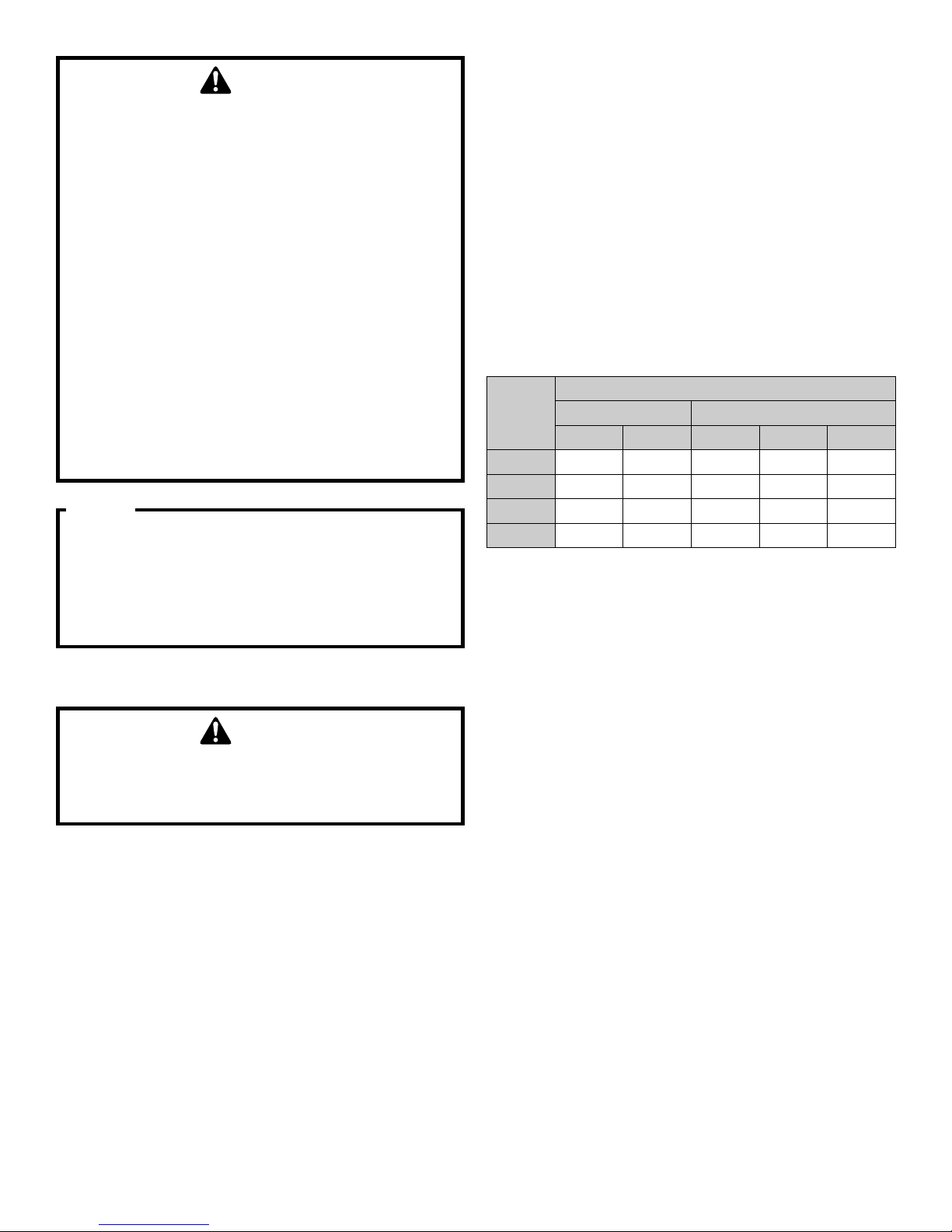
1/4 3/8 5/8 3/4 7/8
1.5 x x x* x
2 x x* x
2.5 x x* x
3 x x* x
Allowable line set diameter
Liquid Suction
x: Allowable combination
*: For marked combinations, if normal ambient op-
eration temperature is less than 14°F, limit line set
length to 50 ft. max.
ReFRigeRant lines
CAUTION
the Compressor pve oIl for r-410A unIts Is extremely sus-
CeptIble to moIsture AbsorptIon And Could CAuse Compressor
fAIlure. do not leAve system open to Atmosphere Any longer
thAn neCessAry for InstAllAtIon.
Use only refrigerant grade (dehydrated and sealed) copper
tubing to connect the air conditioner with the indoor evaporator. After cutting the tubing, install plugs to keep refrigerant
tubing clean and dry prior to and during installation. Tubing
should always be cut square keeping ends round and free
from burrs. Clean the tubing to prevent contamination. The
liquid line must be insulated if more than 50 ft. of liquid line will
pass through an area that may reach temperatures of 30°F
or higher than outdoor ambient. Never attach a liquid line to
any uninsulated portion of the suction line.
Do NOT let refrigerant lines come in direct contact with plumb-
ing, ductwork, oor joists, wall studs, oors, and walls. When
running refrigerant lines through a foundation or wall, openings should allow for sound and vibration absorbing material
to be placed or installed between tubing and foundation. Any
gap between foundation or wall and refrigerant lines should
be lled with a pliable silicon-based caulk, RTV or a vibration
6

EnglishEnglish
Condenser BELOW Evaporator
Mounting the evaporator coil above the
air conditioner will require an inverted loop
in the suction line adjacent or near the
connection to the evaporator.
The top of the loop must be slightly higher
than the top of the coil. The trap can prevent
liquid compression of the compressor for
start- up period.
Liquid Line
Maximum
vertical
Suction Line
elevation
of 90 ft.
Maximum line set equivalent length 125 ft*.
The maximum line set actual length is 100 ft.
*Includes pressure losses of any elbows, bends, etc.
(See page #13 for calculations)
Condenser ABOVE Evaporator
Mounting the air conditioner above the evaporator coil will require an
oil trap that is vertically centered between the air conditioner and
indoor unit the vertical elevation exceeds 80 ft.
The trap can be constructed from standard refrigerant fittings as shown
in the figure (bottom left).
Maximum line set
equivalent length of 125 ft*.
The maximum line set
actual length is 100 ft.
Maximum vertical
elevation of 100 ft.
Trap Construction
LONG RADIUS
STREET ELL
45°
ELL
45°
SHORT RADIUS
STREET ELL
STREET
ELL
*Included pressure losses of any elbows, bends, etc.
(See page #13 for calculations)
77
ReFRigeRant line ConneCtions
leak testing (nitRogen oR nitRogen-tRaCed)
IMPORTANT
To avoid overheating the service valve, sensors, or lter
drier while brazing, wrap the component with a wet rag,
or use a thermal heat trap compound. Be sure to follow
the manufacturer’s instruction when using the heat trap
compound.
Note: Remove Schrader valves from service valves before
brazing tubes to the valves. Use a brazing alloy of 2%
minimum silver content. Do not use ux.
Torch heat required to braze tubes of various sizes is
proportional to the size of the tube. Tubes of smaller size
require less heat to bring the tube to brazing temperature
before adding brazing alloy. Applying too much heat to any
tube can melt the tube. Service personnel must use the
appropriate heat level for the size of the tube being brazed.
NOTE: The use of a heat shield when brazing is recom-
mended to avoid burning the serial plate or the nish on
the unit.
1. The ends of the refrigerant lines must be cut square,
deburred, cleaned, and be round and free from nicks
or dents. Any other condition increases the chance of
a refrigerant leak.
2. Purge with nitrogen at 2 to 3 psig during brazing
to prevent the formation of copper-oxide inside
the refrigerant lines. The PVE oils used in R-410A
applications will clean any copper-oxide present
from the inside of the refrigerant lines and spread it
throughout the system. This may cause a blockage or
failure of the metering device.
3. After brazing, quench the joints with water or a wet
cloth to prevent overheating of the service valve.
4. A bi-ow lter drier is shipped with the unit as a
separate component and must be brazed on by the
installer on-site. Ensure the bi-ow lter drier paint
nish is intact after brazing. If the paint of the steel
lter drier has been burned or chipped, repaint or treat
with a rust inhibitor.
The recommended location of the lter drier is before the
expansion device at the indoor unit.
WARNING
to AvoId the rIsK of fIre or explosIon, never use oxygen, hIgh
pressure AIr or flAmmAble gAses for leAK testIng of A refrIg-
erAtIon system.
WARNING
to AvoId possIble explosIon, the lIne from the nItrogen CylInder
must InClude A pressure regulAtor And A pressure relIef vAlve.
t
he pressure relIef vAlve must be set to open At no more thAn
150
psIg.
To locate leaks, pressure test the system using dry nitrogen
or leak detector uid per Daikin’s recommendation. If you wish
to use a leak detector.
• Charge the system to 10 psi using the appropriate refrigerant.
• Use nitrogen to nish charging the system to working
pressure.
• Apply the detector to suspect areas.
If leaks are found, repair them. After repair, repeat the pressure test. If no leaks exist, proceed to System Start-up
Procedure.
system staRt-uP PRoCeduRe
GENERAL NOTES:
Adequate refrigerant charge for the matching indoor coil and
line set is supplied with the air conditioner. If liquid line set
exceeds factory charge length, refrigerant should be added
at 0.6 ounce (Liquid line diameter 3/8”) or 0.23 ounce (Liquid
line diameter 1/4”) of refrigerant perfoot of liquid line.
NOTICE
vIolAtIon of epA regulAtIons mAy result In fInes or other
penAltIes.
NOTICE
All unIts should hAve A hIgh voltAge power supply ConneCted
2 hours prIor to stArtup.
NOTE: Be careful not to kink or dent refrigerant lines. Kinked
or dented lines will cause poor performance or compressor
damage.
Do NOT make nal refrigerant line connection until plugs
are removed from refrigerant tubing.
WARNING
refrIgerAnt under pressure!
•
do not overChArge system wIth refrIgerAnt.
•do not operAte unIt In A vACuum or At negAtIve pressure.
f
AIlure to follow proper proCedures mAy CAuse property dAm-
Age, personAl Injury or deAth.
CAUTION
operAtIng the Compressor wIth the suCtIon vAlve Closed wIll
CAuse serIous Compressor dAmAge - suCh dAmAge Is not Covered
by our wArrAntIes.
8
English
CAUTION
use refrIgerAnt CertIfIed to AhrI stAndArds. used refrIgerAnt
mAy CAuse Compressor dAmAge, And Is not Covered under the
wArrAnty. most portAble mAChInes CAnnot CleAn used refrIger-
Ant to meet AhrI stAndArds.
staRt-uP PRoCeduRe detail
Air conditioner liquid and suction valves are closed to contain
the charge within the unit. The unit is shipped with the valve
stems closed and caps installed. Do not open valves until
the indoor coil and line set is evacuated.
CAUTION
prolonged operAtIon At suCtIon pressures less thAn 20 psIg
for more thAn 5 seConds wIll result In overheAtIng of the Com-
pressor And mAy CAuse permAnent dAmAge to It.
1. Connect the vacuum pump with 250 micron capability
to the service valves.
2. Evacuate the system to 500 microns or less using
suction and liquid service valves. Using both valves
is nec essary.
3. Close pump valve and hold vacuum for 10 minutes.
Typically pressure will rise during this period.
• If the pressure rises to 500 microns or less and
remains steady the system is considered leak-free;
proceed to start-up.
• If pressure rises above 500 microns moisture and/
or noncondensibles may be present or the system
may have a small leak. Return to step 2: If the same
result is encountered check for leaks as previously
indicated and repair as necessary then repeat
evacuation.
• If pressure rises above 500 microns, a leak is present. Check for leaks as previously indicated and
repair as necessary then repeat evacuation.
eleCtRiCal ConneCtions
WARNING
HIGH VOLTAGE!
dIsConneCt All power before servICIng.
m
ultIple power sourCes mAy be present. fAIlure
to do so mAy CAuse property dAmAge, personAl
Injury or deAth due to eleCtrIC shoCK. wIrIng must
Conform wIth neC or CeC And All loCAl Codes.
u
ndersIzed wIres Could CAuse poor equIpment
performAnCe, equIpment dAmAge or fIre.
WARNING
to AvoId the rIsK of fIre or equIpment dAmAge, use Copper
ConduCtors.
CAUTION
groundIng requIred!
AlwAys InspeCt And use proper servICe tools. lACK of InspeC-
tIon or Improper tools mAy CAuse equIpment dAmAge or personAl
Injury. All dIsConneCted groundIng devICes must be reCon-
neCted before InstAllIng or servICIng. multIple Components of
thIs unIt mAy ConduCt eleCtrICAl Current; these Are grounded.
I
f servICIng the unIt, Any dIsConneCtIon of groundIng wIres,
sCrews, strAps, ClIps, nuts or wAshers used to Complete the
ground must be returned to theIr orIgInAl posItIon And prop-
erly fAstened.
NOTICE
•never InstAll A phAse-AdvAnCIng CApACItor. As thIs unIt Is
equIpped wIth An Inverter, InstAllIng A phAse-AdvAnCIng CApACI-
tor wIll not only deterIorAte power fACtor Improvement ef-
feCt, but Also mAy CAuse CApACItor AbnormAl heAtIng ACCIdent
due to hIgh-frequenCy wAves.
•do not ChAnge the settIng of the proteCtIon devICes. If the
pressure swItCh, thermAl swItCh, or other proteCtIon devICe
Is shorted And operAted forCIbly, or pArts other thAn those
speCIfIed by dAIKIn Are used, fIre or explosIon Could result.
•do not ConneCt the ground wIre to suCtIon lIne, sewAge pIpes,
lIghtnIng rods, or telephone ground wIres.
The air conditioner rating plate lists pertinent electrical data
necessary for proper electrical service and overcurrent protection. Wires should be sized to limit voltage drop to 2% (max.)
from the main breaker or fuse panel to the air conditioner.
Consult the NEC, CEC, and all local codes to determine the
correct wire gauge and length.
Local codes often require a disconnect switch located near
the unit; do not install the switch on the unit.
overCurrent proteCtIon
The inverter control system software provides suf cient time
delay to protect from overcurrent conditions and permit the
compressor and fan motors to adjust their rotational speed.
9
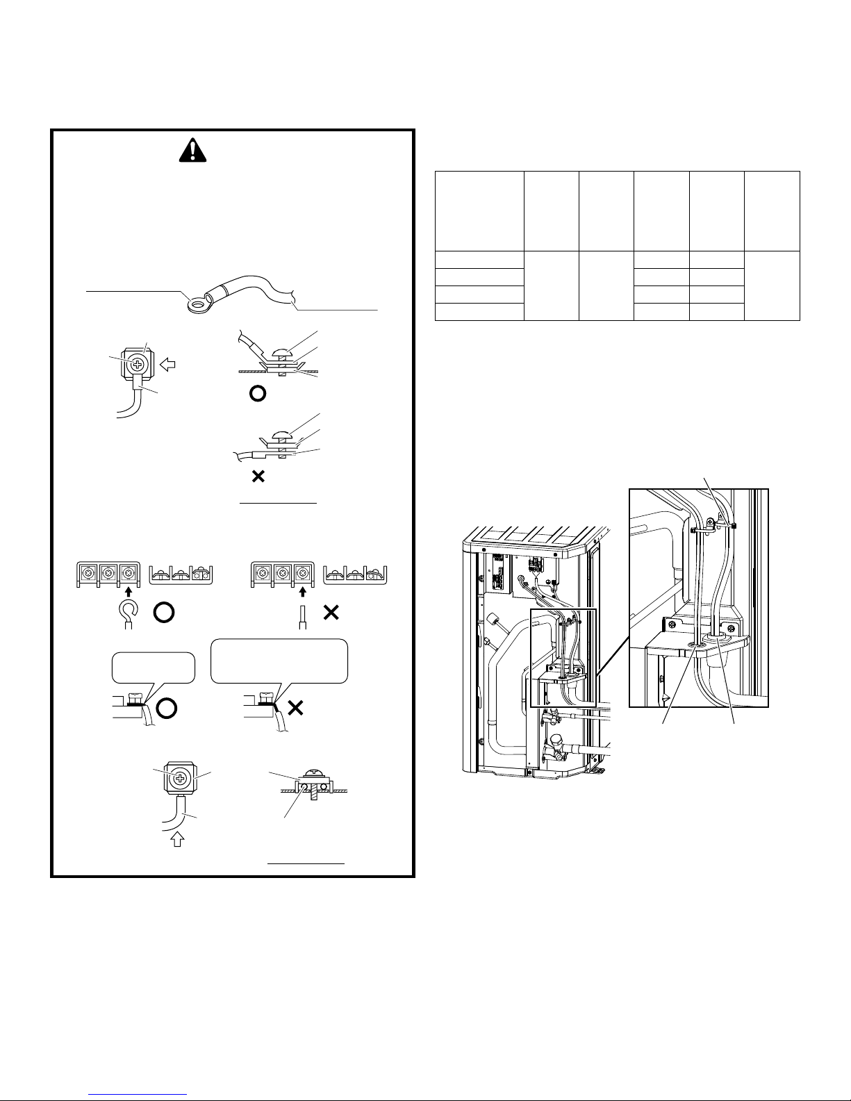
hIgh voltAge ConneCtIons
Route power supply and ground wires through the high voltage port and terminate in accordance with the wiring diagram
provided inside the black plastic cover over control box.
CAUTION
•preCAutIons to be tAKen for power supply wIrIng.
when usIng strAnded wIres, mAKe sure to use A round CrImp-
style termInAl for ConneCtIon to the power supply termInAl
bloCK.
plACe the round CrImp-style termInAls on the wIres up to the
Covered pArt And seCure In plACe.
Round crimp-style
terminal
Stranded wire
Flat washer
Screw
A
Round
crimp-style
terminal
Good
Wrong
Arrow view A
•when ConneCtIng the ConneCtIon wIres to the termInAl bloCK
usIng A sIngle Core wIre, be sure to Curl the end of the leAd.
Improper worK mAy CAuse heAt And fIres.
Screw
Round crimpstyle terminal
Flat washer
Screw
Flat washer
Round crimpstyle terminal
• When using residual current operated circuit breakers, be
sure to use a high-speed type (0.1 seconds or less) 200
mA rated residual operating current.
• Use copper conductors only.
• Use insulated wire for the power cord.
• Select the power supply cable type and size in accor-
dance with relevant local and national regulations.
MODEL NAME
DX17VSS181AA
DX17VSS241AA 17.4 A 20 A
DX17VSS301AA 22.7 A 25 A
DX17VSS361AA 22.7 A 25 A
Phase
and fre-
quency
1 Phase
60Hz
Voltage
208/230V
MCA
(Min.
circuit
amp.)
12.7 A 15 A
MOP
(Max.
overcur-
rent
protective
device)
Transmis-
sion line
selection
18 AWG
(typical)
low voltAge ConneCtIons
The unit is designed to work as part of a fully communicating
HVAC system, utilizing a ComfortNet™ CTK04 thermostat,
ComfortNet compatible indoor unit, and up to four wires. Route
control wires through the low voltage port and terminate in accordance with the wiring diagram provided inside the top plate.
Tie high voltage wire with
clamp material (accessory)
Good
Strip wire end
to this point.
Excessive strip length
may cause electric shock
or current leakage.
Good
Wrong
Wrong
•use the followIng method when InstAllIng A sIngle Core wIre.
Screw
B
Flat
washer
A single core wire
Arrow view B
• Make sure to apply the rated voltage of 208/230V for the
unit.
• A power circuit (see the following table) must be provided
for connection of the unit. This circuit must be protected
with the required safety devices.
LOW
VOLTAGE
HIGH
VOLTAGE
Voltage Ports
NOTE: The communicating thermostat is able to search and
identify the indoor and outdoor units when power is applied to
the system. Refer to the communicating thermostat’s installation instruction manual for more information.
Connect low voltage communication wires (1, 2) to low voltage pigtail provided.
CommuniCation WiRing
NOTE: A removable plug connector is provided with the
control board to make thermostat wire connections. This
plug may be removed, wire connections made to the plug,
and replaced. It is STRONGLY recommended that you do not
connect multiple wires into a single terminal.
10
English
Typical 18 AWG wire may be used to wire the system components. However, communications reliability may be improved
by using a high quality, shielded, twisted pair cable for the
data transmission lines.
ATTENTION INSTALLER -
IMPORTANT NOTICE!
Please read carefully before installing this unit.
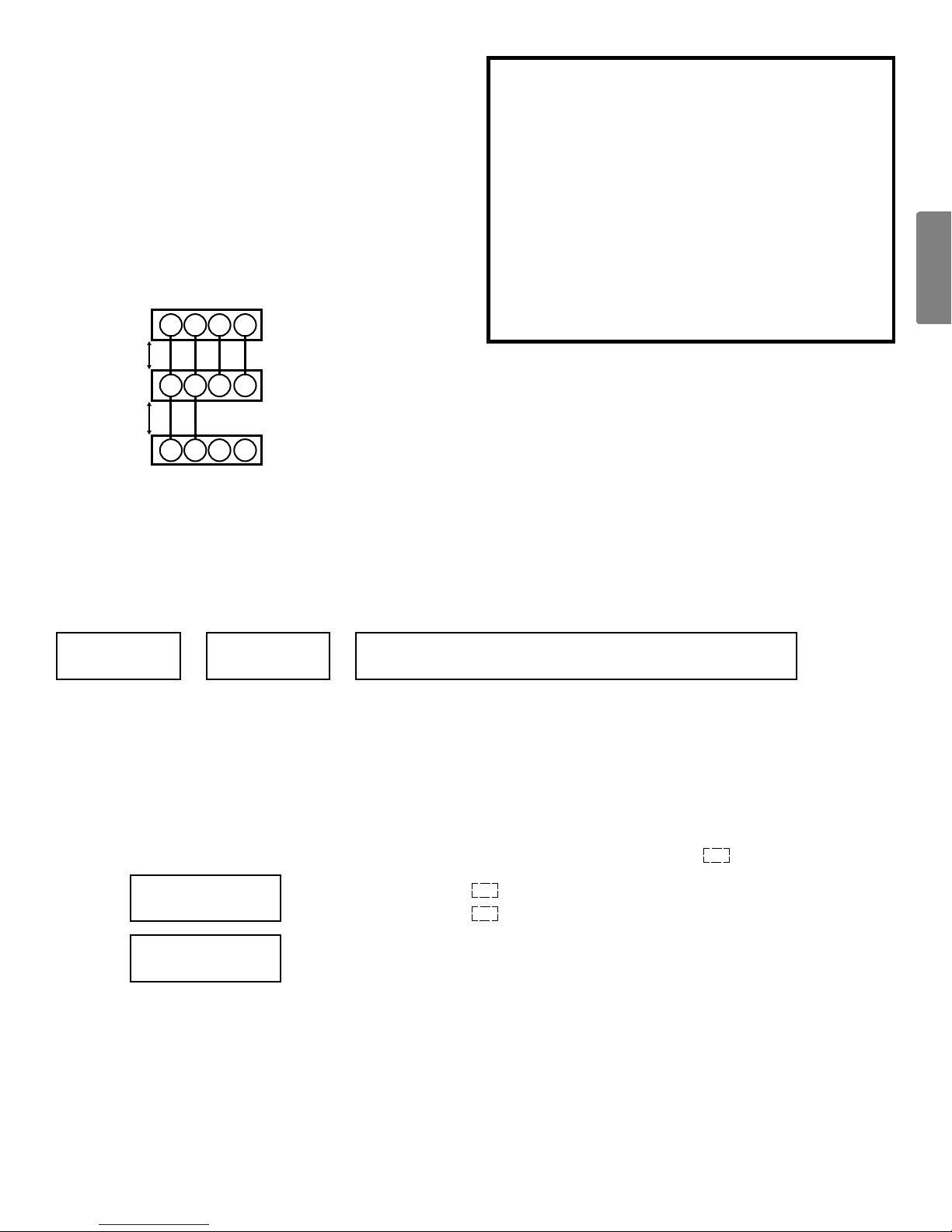
Two-wire ouTdoor, Four-wire indoor wiring
Low voltage wiring consists of two wires between the indoor
unit and outdoor unit and four wires between the indoor unit
and thermostat. The required wires are data lines 1 and 2,
“R” (24 VAC hot) and “C” (24 VAC common).
Never connect the power wiring to communication terminal.
(1, 2, R, C)
Allowable
Maximum
Length
125 Ft.
250 Ft.
1 2 R C
1 2 R C
1 2 R C
System Wiring
CTK04
Thermostat
Compatible
Furnace/A-coil/Blower
Integrated Control Module
Compatible AC
Integrated Control Module
• For DX17VSS, do NOT install the 24 Volt Transformer
that is included with the CTK04 Thermostat.
• Do not attach any wires to the R & C Terminals on the
Air Conditioner, as they are not needed for inverter
unit.
• Data line terminal #1 from outdoor unit must connect
to terminal #1 on indoor unit and thermostat and data
line terminal #2 from outdoor unit must connect to
terminal #2 on indoor unit and thermostat. Verify wires
are not reversed.
STep 1. CalCulaTe reFrigeranT Charge BaSed on line SeT lengTh
The condenser unit is shipped with a predetermined factory charge level as shown below. For longer line sets greater than
15 ft., with CAPEA or 12 ft. with CHPE (Detail shown in tables on page 12) add 0.6 ounce (Liquid line diameter 3/8”) or 0.23
ounce(Liquidlinediameter1/4”)ofrefrigerantperfoot.Refertothefollowingpagefortheequivalentlengthoftheelbowttings.
Total Refriger-
ant (A)
(A) to (C) parameters are calculated/followed below.
(A) There is 2 way calculation for total refrigerant amount
(A)-1 Select line set length from (A)-1 table. If suction line diameter is different from (A)-1 table, then adjust suction line
(A)-2
(B) Pick up from name plate which has factory charge amount.
(C) Calculate above formula. (C)-1 and (C)-2 shown below.
Subtract factory charge length (see (A)-1 Table) from the overall length and put the results in
Additional Charge for
liquid line (C)-1
Adjust among from
suction line (C)-2
Factory Charge
=
refrigerant by using (C)-2 factors.
Calculate from above formula by using (B), (C)-1 and (C)-2 factors.
(B)
=
=
+
[For liquid Line (C)-1] – [Adjust amount from suction line (C)-2]
(in case of 3/8” liquid line) ft. x 0.6 oz.
(in case of 1/4” liquid line)
Check the suction line diameter and
pick the adjust amount (oz.)
Additional Charge (C)
ft.
ft. x 0.23 oz.
11
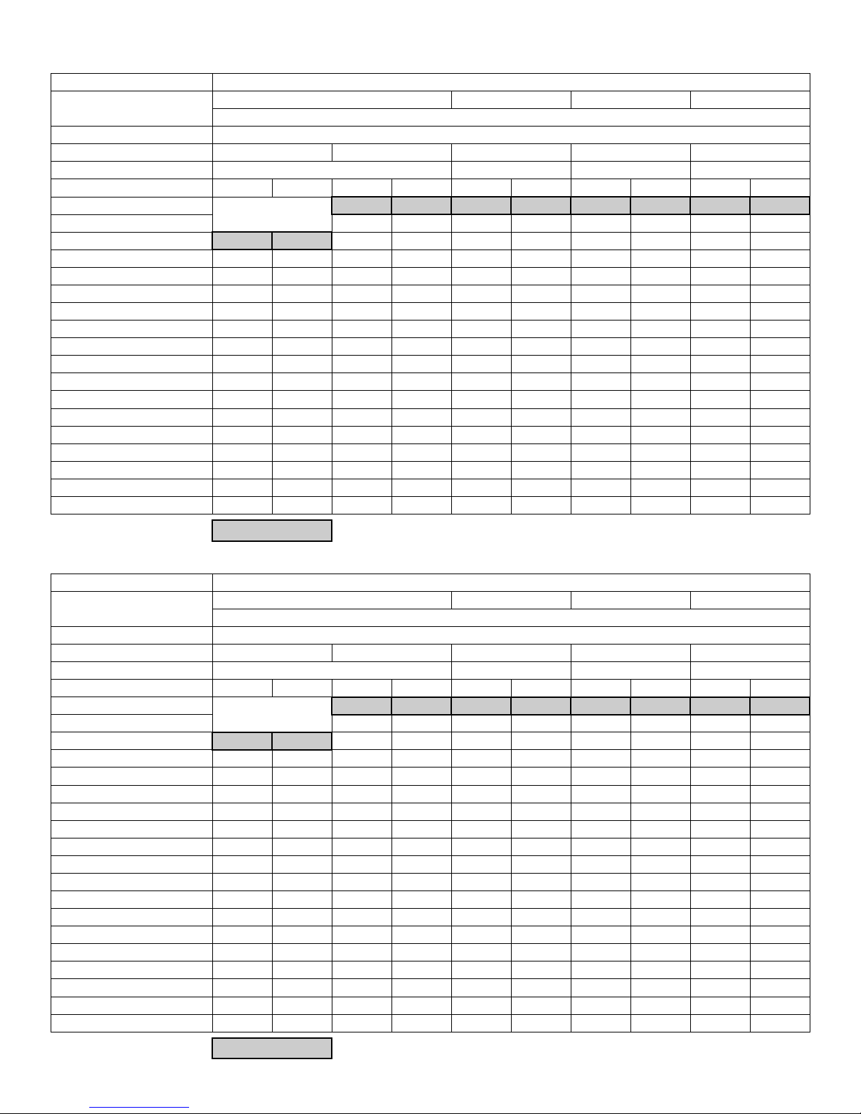
Charge Table for Total/Additional Refrigerant (A)-1 CAPEA Connection
Unit Tonnage
Actual Line Set Length (ft.)
Indoor UNIT CAPEA
Liquid Line Diameter (inch) 1/4” 3/8” 3/8” 3/8” 3/8”
Suction Line Diameter (inch) 3/4” 3/4” 7/8” 7/8”
Total/Additional Total Additional Total Additional Total Additional Total Additional Total Additional
15
20 79 3 79 3 82 3 88 3
25 76 0 82 6 82 6 85 6 91 6
30 77 1 85 9 85 9 88 9 94 9
35 78 2 88 12 88 12 91 12 97 12
40 79 3 91 15 91 15 94 15 100 15
45 81 5 94 18 94 18 97 18 103 18
50 82 6 97 21 97 21 100 21 106 21
55 83 7 100 24 100 24 103 24 109 24
60 84 8 103 27 103 27 106 27 112 27
65 85 9 106 30 106 30 109 30 115 30
70 86 10 109 33 109 33 112 33 118 33
75 88 12 112 36 112 36 115 36 121 36
80 89 13 115 39 115 39 118 39 124 39
85 90 14 118 42 118 42 121 42 127 42
90 91 15 121 45 121 45 124 45 130 45
95 92 16 124 48 124 48 127 48 133 48
100 93 17 127 51 127 51 130 51 136 51
n/a
1.5 Ton 2.0 Ton 2.5 Ton 3.0 Ton
Total/Additional refrigerant (oz.)
76 0 76 0 79 0 85 0
Factory Charge
Charge Table for Total/Additional Refrigerant (A)-1 CHPE Connection
Unit Tonnage
Actual Line Set Length (ft.)
Indoor UNIT CHPE
Liquid Line Diameter (inch) 1/4” 3/8” 3/8” 3/8” 3/8”
Suction Line Diameter (inch) 3/4” 3/4” 7/8” 7/8”
Total/Additional Total Additional Total Additional Total Additional Total Additional Total Additional
12
15 78 2 78 2 81 2 87 2
20 76 0 81 5 81 5 84 5 90 5
25 77 1 84 8 84 8 87 8 93 8
30 78 2 87 11 87 11 90 11 96 11
35 79 3 90 14 90 14 93 14 99 14
40 81 5 93 17 93 17 96 17 102 17
45 82 6 96 20 96 20 99 20 105 20
50 83 7 99 23 99 23 102 23 108 23
55 84 8 102 26 102 26 105 26 111 26
60 85 9 105 29 105 29 108 29 114 29
65 86 10 108 32 108 32 111 32 117 32
70 88 12 111 35 111 35 114 35 120 35
75 89 13 114 38 114 38 117 38 123 38
80 90 14 117 41 117 41 120 41 126 41
85 91 15 120 44 120 44 123 44 129 44
90 92 16 123 47 123 47 126 47 132 47
95 93 17 126 50 126 50 129 50 135 50
100 94 18 129 53 129 53 132 53 138 53
n/a
1.5 Ton 2.0 Ton 2.5 Ton 3.0 Ton
Total/Additional refrigerant (oz.)
76 0 76 0 79 0 85 0
Factory Charge
1212
English
Charge Table for Adjusting charge from suction pipe size
(C)-2
Actual Line Set
Length (ft.)
Suction Line
Diameter (inch)
12-15 1 - 1 -
20-25 2 - 2 -
30-40 3 - 3 -
40-50 4 - 4 -
50-60 5 - 5 -
60-70 5 - 6 -
70-80 6 - 7 -
80-90 7 - 8 -
90-100 8 - 9 -
1.5 - 2.0 Ton 2.5 - 3.0 Ton
5/8” 6/8” 6/8” 7/8”
Unit Tonnage
Adjust refrigerant (oz.)
steP 2. ConneCt aiR ConditioneR to system
CAUTION
open the lIquId vAlve fIrst!
If the suCtIon servICe vAlve Is opened fIrst, oIl from the Com-
pressor mAy be drAwn Into the Indoor CoIl, restrICtIng refrIger-
Ant flow And AffeCtIng operAtIon of the system.
After the refrigerant charge has bled into the system, open
the liquid service valve. The service valve cap is the secondary seal for the valves and must be properly tightened to
prevent leaks. Make sure cap is clean and apply refrigerant
oil to threads and sealing surface on inside of cap. Tighten
cap nger-tight and then tighten additional 1/6 of a turn to
properly seat the sealing surfaces.
Break vacuum by fully opening liquid and suction base valve.
NOTE: Units have front seating valves. These are not backseating valves. It is not necessary to force the stem tightly
against the rolled lip.
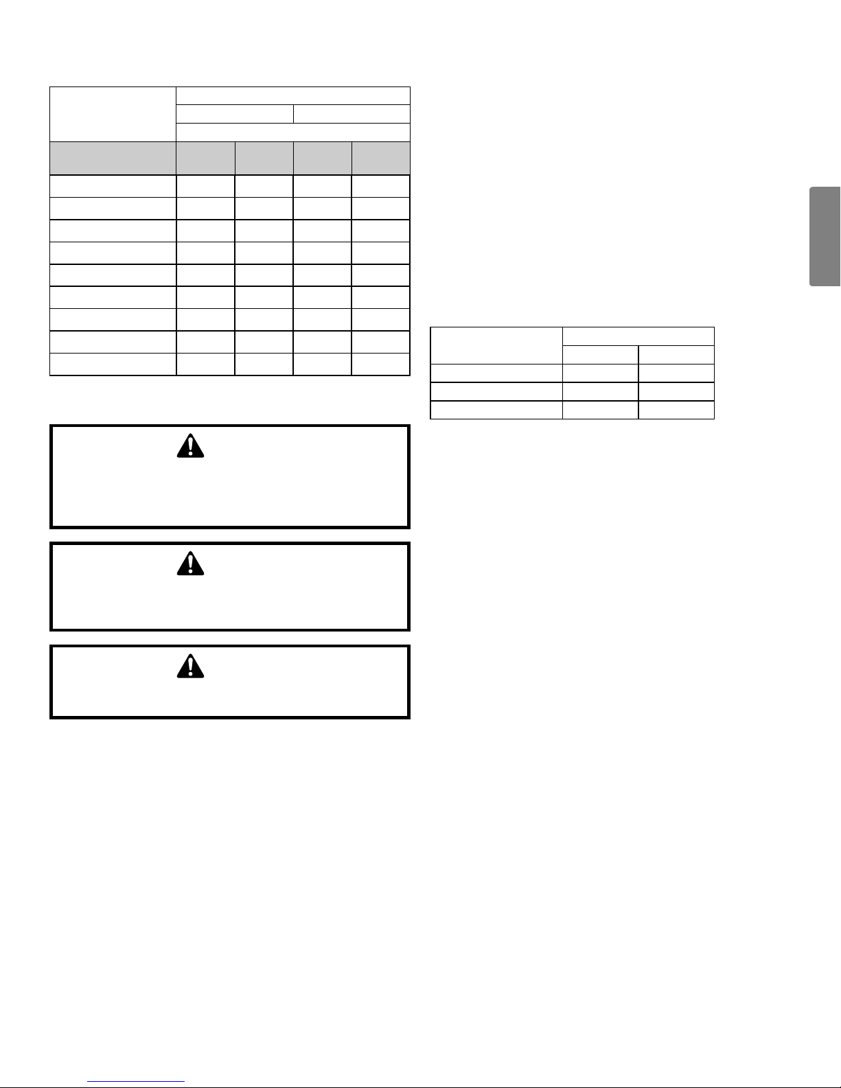
equIvAlent length CAlCulAtIon
NOTE: The following table lists the equivalent length gained
from adding bends to the suction line. Properly size the suction line to minimize capacity loss.
Type of Elbow Fitting
90° short radius 1 3/4 2
90° long radius 1 1/2 1 3/4
45° 3/4 13/16
Inside Diameter (inches)
3/4 7/8
CAUTION
possIble refrIgerAnt leAK!
to AvoId A possIble refrIgerAnt leAK, open the servICe vAlves
untIl the top of the stem Is 1/8” from the retAIner.
CAUTION
ensure vAlves Are open And AddItIonAl ChArge Is Added per
ChArt before ApplyIng power.
Charge additional refrigerant calculated by STEP formula &
table from liquid service valve. (NOT from suction side.)
When opening service valves, open each valve only until the
top of the stem is 1/8” from the valve. To avoid loss of refrigerant, DO NOT apply pressure to the retainer. When opening
valves without a retainer, remove service valve cap and insert
a hex wrench into the valve stem and back out the stem by
turning the hex wrench counterclockwise.
13
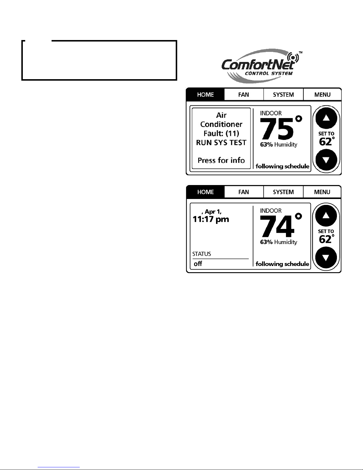
steP 3. system staRt-uP test
NOTICE
on InItIAl power stArt-up, the outdoor unIt wIll dIsplAy Code
e11,
sIgnAlIng thAt InItIAl system test must be run. follow
the Comfortnet™ setup sCreen to enter ApplICAtIon-unIque
InformAtIon. see Comfortnet thermostAt mAnuAl for detAIled
InformAtIon.
A system test is now required to check the equipment settings
and functionality. Once selected, it checks the equipment for
approximately 10 - 15 minutes. System test may exceed 15
minutes if there is an error. Refer to the Troubleshooting section, if error code appears.
Before starting the SYSTEM TEST, turn off the electric heater
or gas furnace.
1. Ensure the thermostat is installed.
2. Apply power to outdoor and indoor units.
3. Start-up.
After the application information is entered,
the initial system test must be run.
The “HOME” screen will be displayed showing
information similar to one of the adjacent screens.
Select “MENU”. Make sure the thermostat is in “OFF” and
select “SYSTEM” menu. Choose “OFF” before “SYSTEM
TEST”.
NOTE:
“SYSTEM TEST” must be run for all installations.
System will not operate without a completed initial
“SYSTEM TEST”.
Sun
2018
1414
English
English
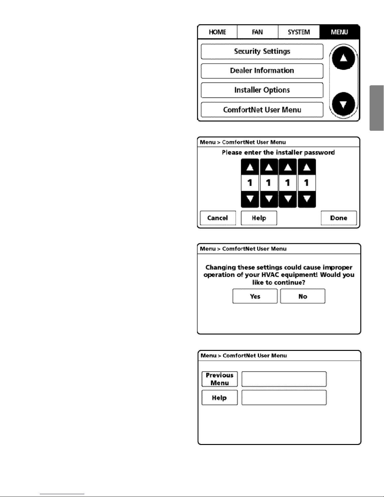
4. From the “MENU” screen, scroll down and select
“ComfortNet User Menu”.
5. Enter Installer password. (The password is the Date
Code located on the thermostat and is available
by entering the “EQUIPMENT STATUS” menu and
scrolling to the bottom.)
6. Conrm message, then select “YES” to continue.
7. From the “ComfortNet User Menu”,
select “Outdoor Unit”.
Indoor Unit
Outdoor Unit
1515
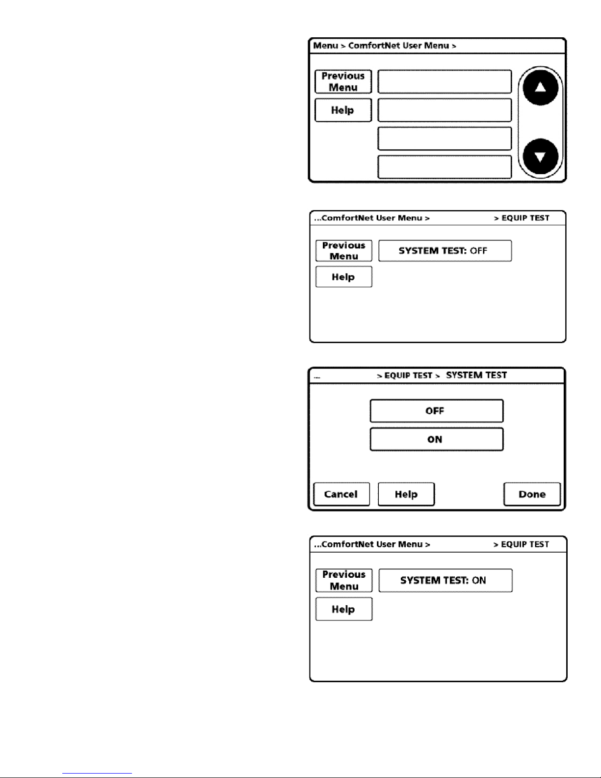
8. Next, scroll down and select “EQUIP TEST”.
Outdoor Unit
SYS SETUP1
SYS SETUP2
EQUIP TEST
Cool Set-up
9. Select “SYSTEM TEST”.
NOTE: If unit has “E15” Error during system test, please
check charging/leaking of refrigerant.
10. Select “ON” to run the “SYSTEM TEST”.
Press “DONE” to initiate test.
Outdoor Unit
Outdoor Unit
11. Allow the system test to run for its duration (10-15
minutes). “EQUIP TEST” screen will show the system
test is “ON” once selected.
System test will operate the outdoor unit and the indoor
unit through a series of startup tests.
Please proceed to the next step and allow for startup
tests to complete. Do not interrupt power to outdoor
unit, indoor unit, or thermostat during system test.
Outdoor Unit
1616
 Loading...