

Daikin DCG090XXX7BXXX, DCG090XXX4BXXX, DCG102XXX3BXXX, DCG120XXX3BXXX, DCG120XXX3VXXX Technical Manual
...
TECHNICAL MANUTECHNICAL MANU
TECHNICAL MANU
TECHNICAL MANUTECHNICAL MANU
ALAL
AL
ALAL
DCG Package Gas Units
7.5 - 12.5 Tons with R410A
• Refer to Service Manual RSD6412007 for installation, operation, and troubleshooting information.
• All safety information must be followed as provided in the Service Manual.
• Refer to the appropriate Parts Catalog for part number information.
• Models listed on page 3.
This manual is to be used by qualified, professionally trained
HVAC technicians only. Daikin does not assume any responsibility
for property damage or personal injury due to improper service
procedures performed by an unqualified person.
Copyright ©2013
RTD6412017
June 2013
TABLE OF CONTENTS
PRODUCT IDENTIFIACTION................................................... 3 - 4
PRODUCT DESIGN
-OVERVIEW............................................................... 5
-LOCATION AND CLEARANCES.................................. 5
-ROOFTOP INSTALLATION..........................................6
-RIGGING INFORMATION............................................ 6
-HIGH ALTITUDE DERATE........................................... 7
A* REVISION UNITS
-PRODUCT DIMENSIONS........................................... 9
-CORNER WEIGHTS..................................................10
-COOLING SPECIFCIATIONS................................11 - 13
-BLOWER PERFORMACE DATA..........................14 - 17
-COOLING PERFORMANCE DATA.......................18 - 26
-WIRING DIAGRAMS...........................................27 - 34
-ACCESSORIES........................................................35
WARNING
WARNING
WARNING
arising from improper service or service procedures. If
you install or perform service on this unit, you assume
responsibility for any personal injury or property damage
which may result. Many jurisdictions require a license to
install or service heating and air conditioning equipment.
WARNING
WARNING
WARNING
WARNING
erty damage, personal injury, reduced unit performance
and/or hazardous conditions may result from the use of
such non-approved devices.
Disconnect ALL power before servicing or installing this unit. Multiple power
sources may be present. Failure to do so may cause property damage, personal
injury or death.
Daikin will not be responsible for
any injury or property damage
The United States Environmental Protection Agency (“EPA”) has issued various regulations regarding the introduction and disposal of refrigerants introduced into this unit. Failure to follow
these regulations may harm the environment and can lead to the imposition of substantial fines.
These regulations may vary by jurisdiction. Should questions arise, contact your local EPA office.
Do not connect or use any device
that is not design certified by Daikin
for use with this unit. Serious prop-
WARNING
HIGH VOLTAGE!
WARNING
WARNING
individuals meeting (at a minimum) the requirements of
an "entry level technician" as specified by the Air-Conditioning, Heating, and Refrigeration Institute (AHRI). Attempting to install or repair this unit without such background may result in product damage, personal injury or
death.
WARNING
WARNING
do not store combustible materials or use gasoline or
other flammable liquids or vapors in the vicinity of this
appliance.
Installation and repair of this unit
should be performed
To prevent the risk of property
damage, personal injury, or death,
ONLY by

PRODUCT IDENTIFICATION
The model number is used for positive identification of component parts used in manufacturing. Please use this number
when requesting service or parts information. NOTE: All unit combinations are not listed below. Models where performance
does not change are not listed individually.
DCG090XXX3BXXX
DCG090XXX4BXXX
DCG090XXX7BXXX
DCG102XXX3BXXX
DCG102XXX4BXXX
DCG102XXX7BXXX
DCG120XXX3BXXX
DCG120XXX3VXXX
DCG120XXX4BXXX
DCG120XXX4VXXX
DCG120XXX7BXXX
DCG120XXX7VXXX
DCG150XXX3BXXX
DCG150XXX4BXXX
DCG150XXX7BXXX
3

PRODUCT IDENTIFICATION
H
g op
g
p
(
(
p
g
g (
g
(
The model number is used for positive identification of component parts used in manufacturing. Please use this number
when requesting service or parts information.
D C C 240 60 3 B * * *
1 2 3 4 , 5, 6 7, 8, 9 10 11 12 13 1 4
A
15 16
*
Brand
Revi sion Leve ls
DDaikin
Configuration
Factory-Installed Options
C Co mmercial Package XNo Options
A Non-powered convenience outlet
Application
B P owered c onvenienc e outlet
CCooling C L ow Ambient Kit
GGas Heat D Return air smoke detector
HHeat Pump E S upply air smoke de tector
F Non-powered convenience outlet;
Low Ambient Kit
Nominal Gross Cooling Capacity
G Non-powered convenience outlet;
036 3 Tons 102 8½ Tons Return air smoke detector
048 4 Tons 120 10 Tons H Non-powered convenience outlet;
060 5 Tons 150 12½ Tons Supp ly ai r smoke detec tor
072 6 Tons 180 15 Tons J Non-powered convenience outlet;
090 7½ Tons 24 0 20 T ons Re turn & Supply ai r sm oke detec tors
K Non-powered convenience outlet;
Nominal Hea ting Capacity
DCG DCC/DC
(Factory-Installed Electric Heat)
Low-ambien t kit; Su pply air smo ke detector
L Non-powered convenience outlet;
045 45,000 BTU/h XXX No Heat Low Ambient Kit;
090 9 0,000 BT U/h 010 10 kW 030 30 kW Return & Supply ai r smoke detec tors
115 115,000 BTU/h 0 15 15 kW 031 30 kW M Pow ered convenience outlet;
140 140,000 BTU/h 016 15 kW 045 45 kW Low Ambient Kit
210 210,000 BT U/h 0 18 18 kW 0 46 46 kW N Pow ered c onveni enc e outlet;
350 350,000 BTU/h 020 20 kW 060 60 kW Return air smoke detector
400 400,000 BTU/h 025 25 kW
O P owered conv eni ence outlet;
Return & Supp ly ai r sm oke de tectors
See p roduc t spe cificat ions for heat size(s) av ailabl e f or eac h capac ity. P P owered conveni ence outlet;
Supp ly ai r smoke de tector
Vol tage
Q P owered conv eni ence outlet;
1 208V 1- Phase 4 4 60V 3-Phase Low Ambient Ki t;
3 208v 3- Phas e 7 5 75V 3-Phaze Return a ir s mo ke dete ctor
R Pow ered conveni ence outlet;
Low Ambient Kit; S upply ai r sm oke d etector
T Powered c onvenienc e outlet;
Supply Fan/Drive Type/Motors
Low Ambient Kit;
B Belt Dr ive V 2-Spe ed B el t Drive Return & Supp ly ai r sm oke de tectors
DDirect Drive U Non-powered convenience outlet;
Low-amb ient k it; Retu rn ai r sm oke det ector
V L ow Ambi ent Kit;
Facto ry -Installe d Options
XNo Options
A Downflow Economizer
H Discon nect Switch (non-fused )
J Downflow Economizer ; Disconnect Switch (non-fused)
Return air smoke detector
W Low Ambient Kit;
Return & Supp ly ai r sm oke de tectors
Y L ow Ambi ent Kit;
Return & Supp ly ai r sm oke de tectors
Z Re tur n & S upp ly ai r sm oke de tectors
Factory-Installed Options
Note: N ot all options available f or all products.
X Standar d A lumi nized Heat Exc hanger
S Stai nle ss S tee l He at Exch ange r
Factory-Installed Options
• S tainless-Steel Heat Exchanger (DCG unit s on ly): A tubular heat exchanger made of 4 09-type
stainless steel is installed in the unit.
• Low-Ambient Kit: Allows for coolin
ambient temperature t o 35ºF o utside air t emperature. On 7½ to 20 ton units, c oolin
outside air tem
•Economizers
• E lectric H eat Kits
• Non-
• Powered Convenience Outlet: A 120V, 15A, GFCI outlet powered with a transformer built into the unit; for use when unit is not runnin
• Dis connect Switch (non-fused): A dis connect swit ch is ins talled in the unit and factory wiring wil l be complete from the sw itch to the unit. Please note
that for ai r conditionin
with the disconnec t switch (non-fused) when it is ordered. Please not e that f or models with a powered convenience outlet option and a disconnect switch
non-fused) option, the power to the powered convenience outlet will be shut off when the disconnect switch (non-fused) is in the off position.
• Ret urn Air and/or Supply Air Smoke Detectors: Return air and/or supply air smoke detectors are installed in the unit.
erature.
Downflow): Based on air conditions, can provide outside air to cool the space.
DCC and DCH unit s only): Available in all voltage options.
owered Convenience Outlet: A 120V,15A,GFCI outlet makes it easier for technicians to service the unit once an electrician runs power to the outlet.
DCC u nit s) and heat pump models (DCH units), the appropriate electric heat kit must be ordered to be f actory-installed alon
eration at lower outdoor temperatures. On the 3-6 ton units, c ooling operation is ex tended for 60ºF
operation i s extended from 35ºF ambient temperature to 0ºF
.
4
Major & Mi nor
PRODUCT DESIGN
DCG Light Commercial Package Gas Units are designed for
outdoor installations only, primarily in light commercial applications and are available in 208-230 volt three phase, 460
volt three phase and 575 volt three phase in 7.5, 8.5, 10 and
12.5 tons with 2 compressors.
The connecting ductwork (Supply and Return) can be connected for either horizontal or vertical airflow. In the vertical
application, a matching Roof Curb is recommended.
The removal of condensate water from the indoor coil can be
achieved by either the 3/4" NPT male fitting on the side of the
unit or by the 3/4" NPT male fitting located on the bottom of
the condensate pan. (Do not reduce the drain line size).
Refrigerant flow control is achieved by use of a flowrater
type metering device.
DCG units use the FasTest Access Fitting System which
consists of a saddle soldered to the suction and liquid lines
and then screwed into the saddle. NOTE: The core must
not be removed from the saddle until the refrigerant
charge has been removed. Failure to do so could result
in property damage or personal injury.
All units have 3-phase belt drive indoor blower motors that
are energized through the blower motor contactor.
For 2 speed models, the indoor blower will operate on low
speed when in "Fan Only" mode or while in first stage 'Cooling" mode. Unit will operate on high speed in "Heating" mode
and while in second stage "Cooling" mode.
Filters are factory supplied in the return air compartment upstream from the indoor coil. The minimum filter area should
not be less than those sizes listed in the Specification Section. Under no circumstances should the unit be operated
without return air filters.
Air for condensing (cooling cycle) is drawn through the outdoor coil by a propeller fan, and is discharged vertically out
the top of the unit. The outdoor coil is designed for .0 static.
No additional restriction (ductwork) shall be applied.
Conditioned air is drawn through the filter(s), across the coil
and back into the conditioned space by the indoor blower.
The DCG series package units use the Compliant Scroll compressor; there are a number of design characteristics which
are different from the traditional reciprocating compressor.
- Due to their design Scroll compressors are inherently more
tolerant of liquid refrigerant. NOTE: Even though the compressor section of a Scroll compressor is more tolerant
of liquid refrigerant, continued flood back or flooded start
conditions may wash oil from the bearing surfaces causing premature bearing failure.
- These Scroll compressors use "POE" or polyolester oil
which is NOT compatible with mineral oil based lubricants
like 3GS. "POE" oil must be used if additional oil is required.
- Compliant scroll compressors perform “quiet” shutdowns
that allow the compressor to restart immediately without
the need for a time delay. This compressor will restart
even if the system has not equalized.
- Operating pressures and amp draws may differ from standard reciprocating compressors. This information may be
found in the “Cooling Performance Data” section.
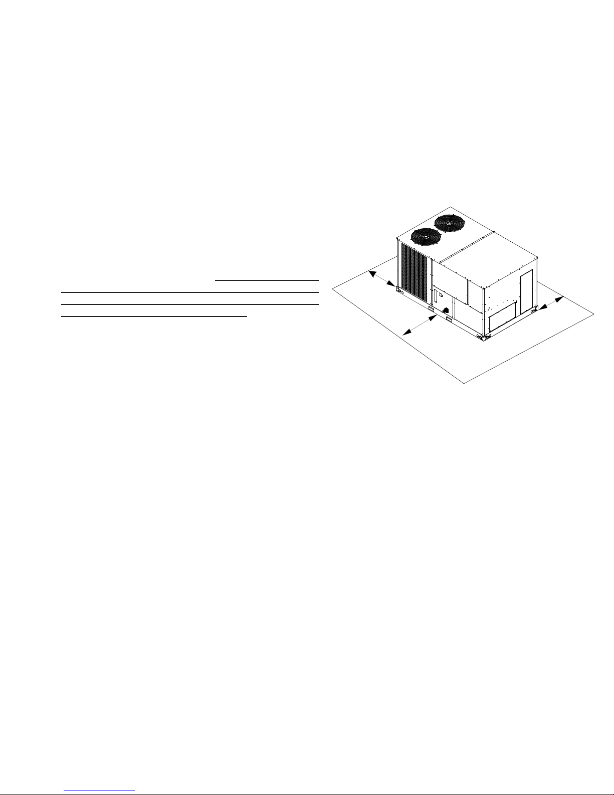
Location and Clearances
36”
Min.*
36”*
Min.
36” Min.*
* In situations that have multiple units a minimum of 48" is
required between the condenser coils.
Outside Slab - Multi-positional
NOTE: A clearance of 48" is recommended on all sides of
the unit and 75" total clearance is recommended on the main
control panel side to facilitate possible fan shaft, coil, electric heat and gas furnace removal. See figure above.
Roof overhang should be no more than 36" and provisions
made to deflect the warm discharge air out from the overhang. Minimum clearances are required to avoid air recirculation and keep the unit operating at peak efficiency.
5
PRODUCT DESIGN
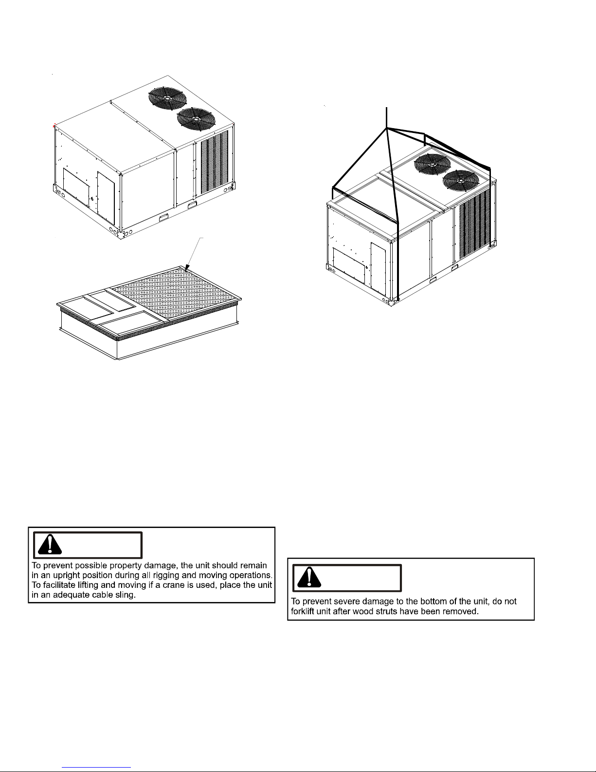
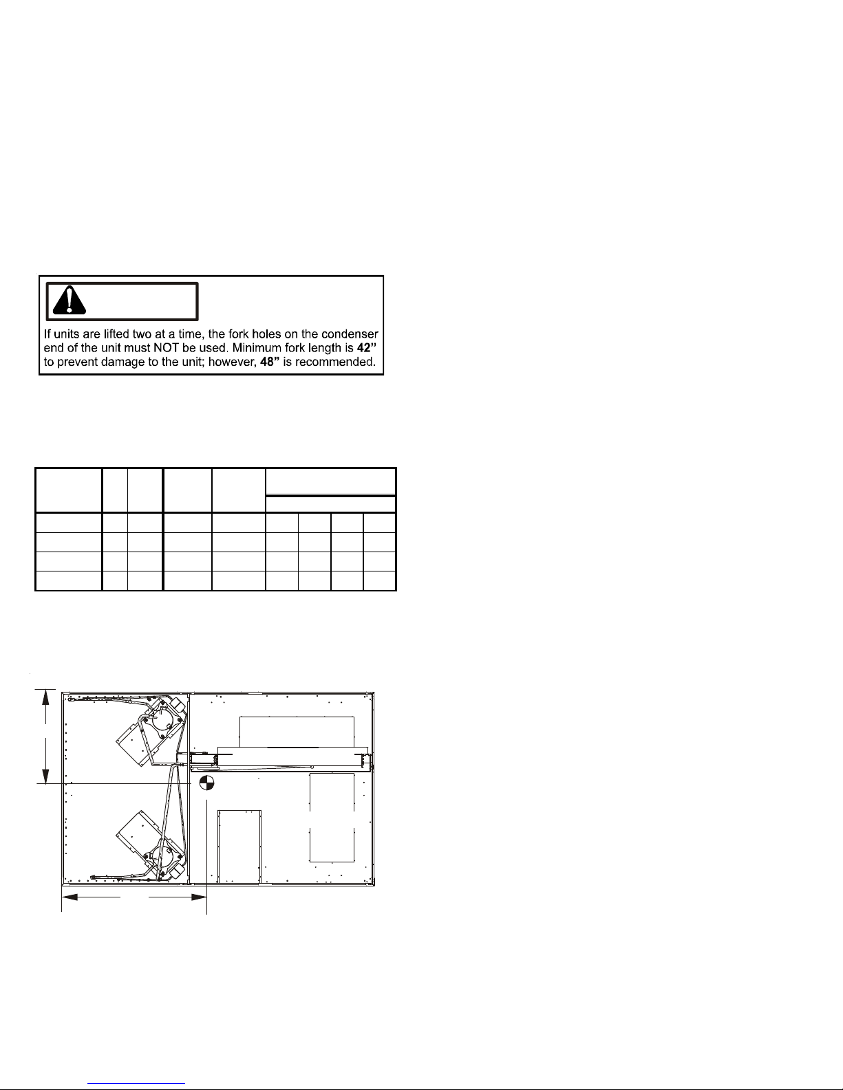
Rigging Information
INSULATED
PAN ELS
Rooftop Installation - Multi-positional
In installations where the unit is installed above ground level
and not serviceable from the ground (Example: Roof Top installations) the installer must provide service platform for service person with rails or guards in accordance with local codes
or ordinances or in their absence with the latest edition of the
National Fuel Gas Code ANSIZ223.1.
NOTE: Units must use roof curb or adaptor (and platform for
leveling, where necessary) to utilize bottom discharge.
WARNING
1. Unit must be lifted by the four lifting holes located at the
base frame corners.
2. Lifting cables should be attached to the unit with shackles.
3. The distance between the crane hook and the top of the
unit must not be less than 60”.
4. Two spreader bars must span over the unit to prevent
damage to the cabinet by the lift cables. Spreader bars
must be of sufficient length so that cables do not come
in contact with the unit during transport. Remove wood
struts mounted beneath unit base frame before setting
unit on roof curb. These struts are intended to protect
unit base frame from forklift damage. Removal is accomplished by extracting the sheet metal retainers and
pulling the struts through the base of the unit. Refer to
rigging label on the unit.
IMPORTANT: When using bottom discharge with roof curb,
ductwork should be attached to the curb prior to installing
the unit.
Refer to Roof Curb Installation Instructions for proper curb
installation. Curbing must be installed in compliance with
the National Roofing Contractors Association Manual.
6
CAUTION

PRODUCT DESIGN
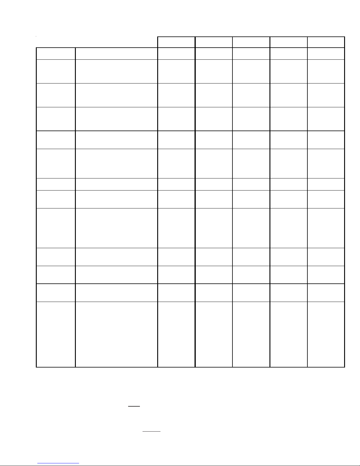
High Altitude Derate - U.S. Installations Only
IMPORTANT NOTE: The gas/electric units naturally derate with altitude. Do not attempt to increase the firing rate by
changing orifices or increasing the manifold pressure. This can cause poor combustion and equipment failure. At all
altitudes, the manifold pressure must be within 0.3 inches W.C. of that listed on the nameplate for the fuel used. At all
altitudes and with either fuel, the air temperature rise must be within the range listed on the unit nameplate. Refer to the
Installation Manual provided with the LP kit for conversion from natural gas to propane gas and for altitude adjustments.
When this package unit is installed at high altitude, the appropriate High Altitude orifice kit must be installed. As altitude
increases, there is a natural reduction in the density of both the gas fuel and combustion air. This kit will provide the proper
design certified input rate within the specified altitude range. High altitude kits are not approved for use in Canada. For
installations above 2,000 feet, use kit HAKT36300. The HAKT36300 kit is used for both Natural and LP gas at high altitudes.
Use LPKT36150 or LPKT180300 propane conversion kit for propane conversions at altitudes below 2000 feet. Natural gas
installations below 2000 feet do not require a kit.
For propane conversions above 2000 feet, high altitude kit HAKT36300 is required in addition to LPKT36150 or LPKT180300
propane conversion kit.
NATURAL GAS AND LP GAS INSTALLATIONS AT ALTITUDES > 2000 FT.
INPUT/BURNER
U.S.
BURNER ORIFICE
CANADA
BURNER ORIFICE
INPUT/BURNER
U.S.
BURNER ORIFICE
CANADA
BURNER ORIFICE
HIGH
ALTITUDE
KIT
2000 3000 4000 4500 5000 6000 7000 8000
35,000 BTUH NAT/33,000 BTUH/L.P.
ELEVATION ABOVE SEA-LEVEL (FEET)
HAKT36300 35/53 36/53 36/53 - 37/53 37/53 38/53 39/54
HAKT36300 35/53 - - 39/54 - - - -
HIGH
ALTITUDE
KIT
2000 3000 4000 4500 5000 6000 7000 8000
50,000 BTUH NAT/45,000 BTUH/L.P.
ELEVATION ABOVE SEA-LEVEL (FEET)
HAKT36300 29/48 30/48 30/49 - 30/49 30/49 31/50 31/50
HAKT36300 29/48 - - 31/50 - - - -
7

DCG Package Gas Units
7.5 - 12.5 Tons with R410A
A* REVISION UNITS
8

PRODUCT DIMENSIONS
UNIT DIMENSIONS
Y
DCG090-150XXX**XXXA*
99 1/8”
61 3/4”
7.5 8.5 10 12.5
Y
52 7/8" 52 7/8" 52 7/8" 58 7/8"
HORIZONTAL DISCHARGE VERTICAL DISCHARGE
6 ½”
12 5/8”
28 3/4”
7 3/8”
RETURN
36 3/8”
5 3/8”
13 7/8”
SUPPLY
6 1/4”
7 1/2”
BOTTOM OF UNIT
9
CORNER WEIGHTS
Corner & Center of Gravity Locations
NOTES:
1. Weights are for basic gas unit; no options.
2. Center of gravity’s weight are for gas units without options.
Provisions for forks have been included in the unit base frame
on three sides. If unit is moved by forklift, no other fork locations are approved.
CAUTION
7.5 - 12.5 TONS
CORNE R WEI GH TS
Model
A* RevX(in)Y(in)
DCG090*
DCG102*
DCG120*
DCG150*
48 32 1175 1100 269 297 254 280
55 36 1055 1030 195 270 240 330
49 34 1215 1140 255 321 250 314
47 33.5 1340 1315 315 370 290 340
Ship p i ng
Weight
(lbs)
Oper ating
Weight
(lbs)
Corner Weights
( lbs )
ABCD
DCG090-150XXX**XXXA*
* Weight s shown ar e belt drive with no accessories.
A
Y
RETURN
C
EVAPORATOR COIL
COMPRESSOR 1
CG
COMPRESSOR 2
SUPPLY
BD
X
CENTER OF GRAVITY - 7.5 - 12.5 TONS
10
PACKAGE GAS SPECIFICATIONS
DCG090***3B*** A*DCG 102***3B* **A*DC G120* **3B*** A*DCG120***3V***
COOLING
CAPACITY
HEATING
CAPACITY
UNIT
ELECTRICAL
SPEC IFICATIO N
HEATING
SECT ION
COMPRE SSOR
CONDE NSER
FAN MOTOR
CONDE NSER FAN
CONDE NSER
COIL
EVAPORATO R
BLOWER
MOTO R
EVAPORATO R
BLOWER
EVAPORATO R
COIL
HEATING
LIMITS
GENERAL
INFO RM ATI ON
COOLI NG CAP ACITY, BTU H 90,000 102,000 116,000 116 ,000 144,000
EER /IEER 11 .5/11 .5 11.3 /11. 5 11. 3 / 11 .5 1 1.3 / 12. 8 10.8/11 .0
HEA TING INP UT 210, 000 210 ,000 210,0 00 210 ,000 21 0,00 0
HEA TING OUT PU T 168, 000 168 ,000 168,0 00 168 ,000 16 8,00 0
STEADY STATE EFFY % 8080808080
TE MPER ATURE RI SE ( °F) 35 - 65 35 - 6 5 25 - 55 25 - 55 15 - 45
VO LTA GE (N AME PLATE ) 208- 23 0/3/ 60 208 -230/ 3/60 208-23 0/3/60 208 -230/3 /60 208-230 /3/60
UNIT AMPS (TOTAL) 34.0 40.8 45 44 59
MINIM UM CIRCUIT AMPA CITY 37.3 4 5.2 49 48 65
MAXIMU M OVERCURREN T PROTECTION
NUMB ER OF B URNERS 6 6 6 6 6
ORIFICE SIZE NATURAL 3434343434
ORIF I CE S IZE LP 52 52 5 2 52 5 2
PRE SSURE SWIT CH SETTING 0.34 0.34 0.3 4 0.34 0.34
TYPE SCROLL SCROLL SCROLL SCR OLL SCRO LL
RAT ED LOA D AMPS 13.1 1 4.5 1 6 16 22.4
LOC KED RO TO R A MPS 83.1 98 110 110 14 9
QUANT ITY O F CONDE NSER FA N M OTOR S 2 2 2 2 2
HOR SE POWER 1/4 1/3 1/3 1/3 1/3
RPM 107 5 1075 1075 1075 10 75
RAT E D LO AD AM PS 1.4 2.4 2.4 2.4 2.4
LOC KED RO TOR AM PS 2.9 5.2 5.2 5.2 5.2
BLADE DIAMETER( ") / # OF BLADES 22/4 22/3 22/3 22/3 22/3
NOM INAL CFM 7,200 8,200 8,200 8,2 00 7,200
FACE AREA - SQ. FT.
NUMB ER OF R OWS
FINS PER INCH
HORSE POWER - TYP E - STAN DARD
NO. OF SPEEDS
RAT E D LO AD AM PS 5.0 7.8 7.8 6.4-6/3. 8 9.4
LOCKED ROTOR AMPS 18 40 40 38-43 / 16.3-18.3 66
MO TOR SP EED TAP - COOLIN G --- --- -- - --- - --
RPM 174 5 172 5 1725 1 750 / 116 5 670 - 950
DIAM ETER X WIDTH ( INCHES) 15X12 15x15 15X15 15X 15 15X15
RAT E D SC FM COOL IN G 300 0 3200 3500 3500 3900
MAX EXTERNAL STATIC PRESS ("w.c.) 1.0 1 .0 0.9 0.9 1.4
FACE AREA - SQ. FT.
NUMB ER OF R OWS
FINS PER INCH
PRIMARY LIMIT SETTING (°F) 200 190 2 00 200 180
AUXI LIARY LIMI T SETT ING (° F) 1 50 18 0 160 160 16 0
ROL LOUT LIM IT SETT I NG ( °F) 350 350 3 50 350 35 0
FILTER SIZE
DRAIN SIZE (INCHES)
EXPANSION DEVICE
REFRIGE RANT CHARG E R-410A (Oz.) C IR #1
REFRIGE RANT CHARG E R-410A (Oz.) C IR #2
POWE R SUP PLY ENT RANCE SIZE (INCHE S) Locating Dimple Loc ating Dim ple Loca ting Dimple Locating Dimple Lo cating Dimple
LOW V OLTAGE ENT RANCE SIZE (INCHE S) Locati ng Dimple Locating Dimple Lo cating Dimpl e Locating Dimple Lo cating Dimple
LOW P RE SSUR E SWIT CH (OP EN /CLOS E-PSIG ) 22/50 22 /50 22/5 0 22/50 2 2/50
HIGH PRESSURE SWI TCH (OPE NS-PS IG) 6 60 660 6 60 660 66 0
SHIPPIN G WEIGHT LBS.
OP ERA TING WEIG HT LB S.
(1)
50 50 6 0 60 80
28.8 35.2 35.2 35. 2 3 9
2 X 22 X 22 X 22 X 22 X 2
27 +/ -1 27±1 27 +/-1 2 7 +/-1 27 + /-1
1.5 - STD STATIC
BELT D RIVE
11121
8.9 10.2 10.2 10.2 1 4.7
44444
16 14 1 4 14 1 5
(4) 16 X 20 x 2 (4) 16 X 24 x 2 (4) 16 X 24 x 2 (4) 16 X 2 4 x 2 (4) 20 X 25 x 2
3/4" 3/4" 3/4" 3/4" 3/4"
Orifi ce ( 0.07 6) O ri fice (0. 080) O rifice (0.086 ) O rifice (0.0 86) O rifice (0.092 )
100 11 5 125 125 17 5
100 11 5 125 125 17 5
1175 1215 1215 1215 1340
1100 1140 1140 1140 1315
DCG090-150XXX3*XXXA*
2.0 - S TD ST A TIC
BELT DRIVE
2.0 - STD STATIC
BELT DR IVE
A*
2.0 - STD STA TIC
BELT DRIVE
DC G15 0***3 B***
A*
3.0 - STD STATIC
BELT DRIVE
(1)
Maximum Overcurrent Protection Device: MUST use Time Delay Fuse or HACR type Circuit Breaker of the same size as noted.
(2)
Rated capacity 350 CFM/Ton, full capacity 400 CFM/Ton
*** NOTE: High static airflow requires installation of high static kit (HSKT*).
Wire size should be determined in accordance with National Electrical Codes. Extensive wire runs will require larger wire sizes.
Unit specifications are subject to change without notice.
IMPORTANT: While this data is presented as a guide, it is important to electrically connect the unit and properly size wires and fuses/circuit breakers
in accordance with the National Electrical Code and/or all local codes. Data shown is w/o electric heaters.
ALWAYS refer to the units serial plate for the most up-to-date general and electrical information.
11
 Loading...