

Daikin DCG036XXX3BXXX, DCG036XXX3DXXX, DCG048XXX3DXXX, DCG048XXX1DXXX, DCG048XXX3BXXX Technical Manual
...
TECHNICAL MANUTECHNICAL MANU
TECHNICAL MANU
TECHNICAL MANUTECHNICAL MANU
ALAL
AL
ALAL
DCG Commercial Gas Units
3 - 6 Tons with R410A
• Refer to Service Manual RSD6412006 for installation, operation, and troubleshooting information.
• All safety information must be followed as provided in the Service Manual.
• Refer to the appropriate Parts Catalog for part number information.
• Models listed on page 4.
This manual is to be used by qualified, professionally trained HVAC
technicians only. Daikin does not assume any responsibility for property
damage or personal injury due to improper service procedures performed by an unqualified person.
Copyright ©2013
RTD6412016
June 2013
TABLE OF CONTENTS
PRODUCT IDENTIFIACTION...................................................3 - 4
PRODUCT DESIGN
-OVERVIEW............................................................... 5
-LOCATION AND CLEARANCES.................................. 5
-ROOFTOP INSTALLATION..........................................6
-RIGGING INFORMATION............................................ 6
-HIGH ALTITUDE DERATE........................................... 7
-BLOWER PERFORMANCE DATA CHART................... 8
ELECTRICAL DATA................................................................. 7 - 9
A* REVISION UNITS
-PRODUCT DIMENSIONS...........................................10
-CORNER WEIGHTS..................................................11
-COOLING SPECIFCIATIONS................................12 - 16
-BLOWER PERFORMACE DATA..........................17 - 22
-HIGH STATIC..........................................21 - 22
-COOLING PERFORMANCE DATA........................23 - 31
-WIRING DIAGRAMS............................................32 - 51
-ACCESSORIES.........................................................52
WARNING
WARNING
WARNING
arising from improper service or service procedures. If
you install or perform service on this unit, you assume
responsibility for any personal injury or property damage
which may result. Many jurisdictions require a license to
install or service heating and air conditioning equipment.
WARNING
WARNING
WARNING
WARNING
erty damage, personal injury, reduced unit performance
and/or hazardous conditions may result from the use of
such non-approved devices.
Disconnect ALL power before servicing or installing this unit. Multiple power
sources may be present. Failure to do so may cause property damage, personal
injury or death.
Daikin will not be responsible for
any injury or property damage
The United States Environmental Protection Agency (“EPA”) has issued various regulations regarding the introduction and disposal of refrigerants introduced into this unit. Failure to follow
these regulations may harm the environment and can lead to the imposition of substantial fines.
These regulations may vary by jurisdiction. Should questions arise, contact your local EPA office.
Do not connect or use any device
that is not design certified by Daikin
for use with this unit. Serious prop-
WARNING
HIGH VOLTAGE!
WARNING
WARNING
try level technician" as specified by the Air-Conditioning,
Heating, and Refrigeration Institute (AHRI) may use this
information. Attempting to install or repair this unit
without such background may result in product damage,
personal injury or death.
WARNING
WARNING
do not store combustible materials or use gasoline or
other flammable liquids or vapors in the vicinity of this
appliance.
ONLY individuals meeting (at a minimum) the requirements of an "en-
To prevent the risk of property
damage, personal injury, or death,
2

PRODUCT IDENTIFICATION
H
The model number is used for positive identification of component parts used in manufacturing. Please use this number
when requesting service or parts information.
D C C 240 60 3 B * * *
1 2 3 4 , 5, 6 7, 8, 9 10 11 12 13 1 4
Brand
DDaikin
Configuration
C Commercial Pa ckage X No Options
A Non-powered convenience outlet
Applica tion
CCooling C Low A mbient Ki t
GGas Heat D Return air smoke detector
HHeat Pump E S upply air smoke de tector
Nominal Gross Cooling Capacity
036 3 Tons 102 8½ Tons Return air smoke detector
048 4 Tons 120 10 Tons H Non-powered convenience outlet;
060 5 Tons 150 12½ Ton s Supp ly air sm oke de tector
072 6 Tons 180 15 Tons J Non-powered convenience outlet;
090 7½ T ons 24 0 20 T ons Return & Supply air sm oke detectors
Nominal Heating Capacity
DCG DCC/DC
045 45,00 0 BTU/h XXX No Heat Low Ambient Kit;
090 9 0,000 BTU/h 0 10 10 kW 030 30 kW Return & Supply air sm oke detectors
115 115,000 BTU/h 015 15 kW 031 30 kW M Powered convenience outlet;
140 140,000 BT U/h 0 16 15 kW 0 45 45 kW Low A mbient Ki t
210 210,000 BTU/h 018 18 kW 046 46 kW N Powered convenience outlet;
350 350,000 BTU/h 020 20 kW 060 60 kW Return air smoke detector
400 400,000 BTU/h 025 25 kW
See p roduc t specific ation s for hea t size(s ) available for each capac ity. P P owered conveni ence outlet;
Vol tage
1 20 8V 1-Ph ase 4 4 60V 3-P hase Low Ambient Kit;
3 20 8v 3-Phase 7 5 75V 3-P haze Ret urn air smoke detect or
Supply Fan/Drive Type/Motors
B B elt D rive V 2 -Speed B elt Drive Ret urn & S upply ai r sm oke dete ctors
DDirect Drive U Non-powered convenience outlet;
Factory-In stalle d Options
XNo Options
A D ownflo w Economizer
H Disconnect Switch (non-fused)
J Do wnflo w Economi zer ; Disconnect Swit ch ( non-fused)
Note: Not all options available for all products.
Factory-Installed Options
• Stainless-Steel Heat Exchanger (DCG unit s only): A tubular heat exchanger made of 409-type
stainless steel is installed in the unit.
• Low-Ambient Kit: Allows for cooling operation at lower outdoor t emperatures. On the 3-6 ton units, cooling operation is extended for 60ºF
ambient temperatu re to 35ºF outsid e air temperature. On 7½ to 20 ton uni ts, cooling op eration is extended from 35ºF ambient temperature to 0ºF
outside air temperature.
• Economizers (D ownflow): Based on air conditions, can prov ide outside air to cool the space.
• Electric Heat Kits (DCC and DCH units only): Available in all voltage options.
• Non-powered C onvenience Outlet: A 120V,15A,GFCI outlet makes it easier for technicians to service the unit once an electrician runs power to the outlet.
• Powered Convenience Outlet: A 120V, 15A, GFCI outlet powered with a transformer built into the unit ; for use when unit is not running.
• Disconnect Switch (non-fused): A dis connect swit ch is installed in the unit and fac tory wiring w ill be complete from the switch to the unit. Please not e
that for air c onditioning (DC C units) and heat pump models (DCH units), the appropriate electric heat kit must be ordered to be factory-installed along
with the disconnect switch (non-fused) when it is ordered. Please note that for models with a powered convenience outlet option and a disconnect switch
(non-fused) opt ion, the power to the powered conv enience outlet will be shut off when the disconnect switch (non-fused) is in the off position.
• Return Air and/or Supply Air Sm oke Detectors: Return air and/or supply air smoke detectors are installed in the unit.
(Factory-Installed Electric Heat)
B P owered convenience outlet
F Non-powered convenience outlet;
G Non-powered convenience outlet;
K Non-powered convenience outlet;
L Non-powered convenience outlet;
O Power ed convenience outlet;
Q Power ed convenience outlet;
R Powered convenience outlet;
T Powered c onvenience outlet;
V L ow Ambient Kit;
W Low Ambient Kit;
Y L ow Ambient Kit;
Z Ret urn & S upply ai r smok e detec tors
X Standard A luminized Hea t Exchan ger
S Stai nless S teel He at Exchanger
*
A
15 16
Revi sion Leve ls
Major & Minor
Fac tory-In stalle d Optio ns
Low Ambient Kit
Low -ambien t kit; Su pply air s moke d etector
Return & Supply air sm oke detectors
Supp ly air sm oke de tector
Low Ambient Kit; Supp ly air sm oke d etector
Low Ambient Kit;
Low- ambient k it; Return air smok e detector
Return air smoke detector
Return & Supply air sm oke detectors
Return & Supply air sm oke detectors
Factory-Installed Options
3

PRODUCT IDENTIFICATION
The model number is used for positive identification of component parts used in manufacturing. Please use this number
when requesting service or parts information. NOTE: All unit combinations are not listed below. Models where performance
does not change are not listed individually.
DCG036XXX1DXXX
DCG036XXX3DXXX
DCG036XXX3BXXX
DCG036XXX4BXXX
DCG036XXX7BXXX
DCG048XXX1DXXX
DCG048XXX3DXXX
DCG048XXX3BXXX
DCG048XXX4BXXX
DCG048XXX7BXXX
DCG060XXX1DXXX
DCG006XXX3DXXX
DCG060XXX3BXXX
DCG060XXX4BXXX
DCG060XXX7BXXX
DCG072XXX3BXXX
DCG072XXX4BXXX
DCG072XXX7BXXX
4
PRODUCT DESIGN
DCG Light Commercial Package Gas Units are designed for
outdoor installations only, primarily in light commercial applications and are available in 208-230 volt single phase, 208230 volt three phase, 460 volt three phase and 575v three
phase in 3 thru 6 ton sizes with 1 compressor.
The connecting ductwork (Supply and Return) can be connected for either horizontal or vertical airflow. In the vertical
application, a matching Roof Curb is recommended.
The removal of condensate water from the indoor coil can be
achieved by either the 3/4" NPT female fitting on the end of
the unit or by the 3/4" NPT female fitting located on the bottom of the condensate pan. (Do not reduce the drain line
size).
Refrigerant flow control is achieved by use of flowrator type
metering device.
DCG units use the FasTest Access Fitting System which
consists of a saddle soldered to the suction and liquid lines
and then screwed into the saddle. NOTE: The core must
not be removed from the saddle until the refrigerant
charge has been removed. Failure to do so could result
in property damage or personal injury.
- Operating pressures and amp draws may differ from standard reciprocating compressors. This information may be
found in the “Cooling Performance Data” section.
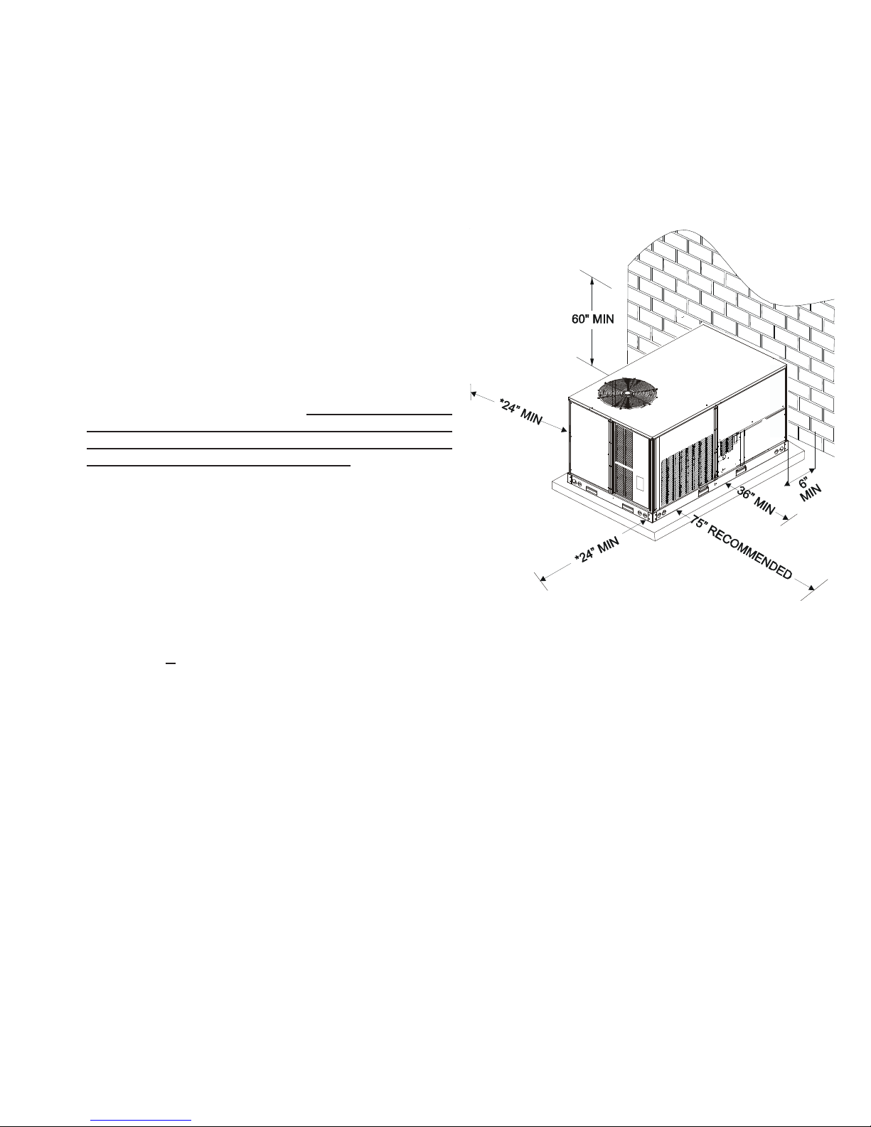
Location and Clearances
Filters are factory supplied in the return air compartment upstream from the indoor coil. The minimum filter area should
not be less than those sizes listed in the Specification Section. Under no circumstances should the unit be operated
without return air filters.
Conditioned air is drawn through the filter(s), across the coil
and back into the conditioned space by the indoor blower.
DCG***XXX*D units indoor blower motors are PSC or EEM
type motors.
DCG***XXX*B units have 3 phase belt drive indoor blower motors that are energized through the blower motor contactor.
Air for condensing (cooling cycle) is drawn through the outdoor coil by a propeller fan, and is discharged vertically out
the top of the unit. The outdoor coil is designed for .0 static.
No additional restriction (ductwork) shall be applied.
DCG series package units use the Compliant Scroll compressor; there are a number of design characteristics which
are different from the traditional reciprocating compressor.
- Due to their design Scroll compressors are inherently more
tolerant of liquid refrigerant. NOTE: Even though the compressor section of a Scroll compressor is more tolerant
of liquid refrigerant, continued flood back or flooded start
conditions may wash oil from the bearing surfaces causing premature bearing failure.
- These Scroll compressors use "POE" or polyolester oil
which is NOT compatible with mineral oil based lubricants
like 3GS. "POE" oil must be used if additional oil is required.
- Compliant scroll compressors perform “quiet” shutdowns
that allow the compressor to restart immediately without
the need for a time delay. This compressor will restart
even if the system has not equalized.
* In situations that have multiple units a minimum of 48" is
required between the condenser coils.
Outside Slab - Multi-positional
NOTE: A clearance of 48" is recommended on all sides of
the unit and 75" total clearance is recommended on the main
control panel side to facilitate possible fan shaft, coil, electric heat and gas furnace removal. See figure above.
Roof overhang should be no more than 36" and provisions
made to deflect the warm discharge air out from the overhang.
Minimum clearances are required to avoid air recirculation
and keep the unit operating at peak efficiency.
5

PRODUCT DESIGN
Rigging Information
INSULATED
PAN ELS
Rooftop Installation
IIn installations where the unit is installed above ground level
and not serviceable from the ground (Example: Roof Top installations) the installer must provide service platform for service person with rails or guards in accordance with local codes
or ordinances or in their absence with the latest edition of the
National Fuel Gas Code ANSIZ223.1.
NOTE: Unit must use roof curb or adaptor (and platform for
leveling, where necessary) to utilize bottom discharge.
WARNING
IMPORTANT: When using bottom discharge with roof curb,
ductwork should be attached to the curb prior to installing
the unit.
Refer to Roof Curb Installation Instructions for proper curb
installation. Curbing must be installed in compliance with
the National Roofing Contractors Association Manual.
1. Unit must be lifted by the four lifting holes located at the
the base frame corners.
2. Lifting cables should be attached to the unit with shackles.
3. The distance between the crane hook and the top of the
unit must not be less than 60”.
4. Two spreader bars must span over the unit to prevent
damage to the cabinet by the lift cables. Spreader bars
must be of sufficient length so that cables do not come
in contact with the unit during transport. Remove wood
struts mounted beneath unit base frame before setting
unit on roof curb. These struts are intended to protect
unit base frame from forklift damage. Removal is accomplished by extracting the sheet metal retainers and
pulling the struts through the base of the unit. Refer to
rigging label on the unit.
CAUTION
6
PRODUCT DESIGN
High Altitude Derate - U.S. Installations Only
IMPORTANT NOTE: The gas/electric units naturally derate with altitude. Do not attempt to increase the firing rate by
changing orifices or increasing the manifold pressure. This can cause poor combustion and equipment failure. At all
altitudes, the manifold pressure must be within 0.3 inches W.C. of that listed on the nameplate for the fuel used. At all
altitudes and with either fuel, the air temperature rise must be within the range listed on the unit nameplate. Refer to the
Installation Manual provided with the LP kit for conversion from natural gas to propane gas and for altitude adjustments.
When this package unit is installed at high altitude, the appropriate High Altitude orifice kit may be installed. As altitude
increases, there is a natural reduction in the density of both the gas fuel and combustion air. This kit will provide the proper
design certified input rate within the specified altitude range. High altitude kits are not approved for use in Canada. For
installations above 2,000 feet, use kit HA-02. The HA-02 kit is used for both Natural and LP gas at high altitudes.
For DCG036045, use LPT-00A propane conversion kit for propane conversions at altitudes below 2000 feet. Natural gas
installations below 2000 feet do not require a kit. For all other 3, 4 and 5 ton models, use LPM-05.
For propane conversion above 2000 feet, high altitude kit HA-02 is required in addition to propane conversion kit LPT-00A
or LPM-05.
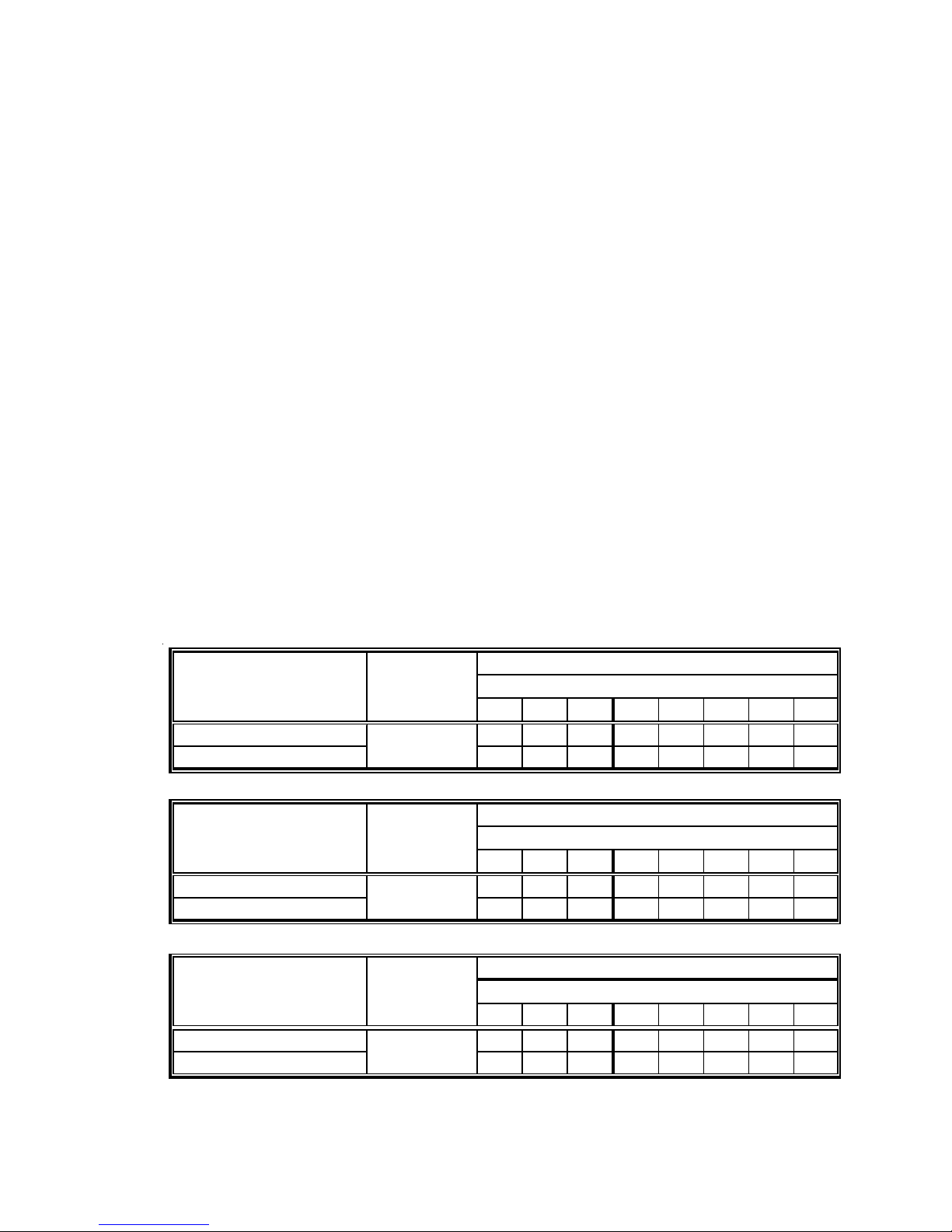
INPUT/BURNER
U.S. BURNER ORIFICE 45/55 47/55 47/56 - 47/56 48/57 48/58 4 9/58
CANADA BURNER ORIFICE 45/55 - - 48/57 - - - -
INPUT/BURNER
U.S. BURNER ORIFICE 44/55 44/55 45/56 - 45/56 46/57 47/58 4 7/58
CANADA BURNER ORIFICE 44/55 - - 47/57 - - - -
INPUT/BURNER
U.S. BURNER ORIFICE 43/55 43/55 44/56 - 44/56 44/56 45/57 4 5/57
CANADA BURNER ORIFICE 43/55 - - 46/57 - - - -
HIGH ALTITUDE
KIT
2000 3000 4000 4 500 5000 6000 7000 8000
HA-02
HIGH ALTITUDE
KIT
2000 3000 4000 4 500 5000 6000 7000 8000
HA-02
HIGH ALTITUDE
KIT
2000 3000 4000 4 500 5000 6000 7000 8000
HA-02
20,000 BTUH NAT/20,000 BTUH/L. P.
ELEVATION ABOVE SEA-L EVEL ( FEET)
22,500 BTUH NAT/20,000 BTUH/L. P.
ELEVATION ABOVE SEA-L EVEL ( FEET)
25,000 BTUH NAT/20,000 BTUH/L. P.
ELEVATION ABOVE SEA-L EVEL ( FEET)
7

PRODUCT DESIGN
÷ CFM
130 140 150
FORMULAS
BTU OUTPUT = CFM x 1.08 x RISE
1.08
BTU OUTPUT
RISE =
100
2400 CFM
2200
2000
1800
1600
1400
1200
1100
1000
900
800
OUTPUT BTU/HR x 1000
90
700
80
BTU OUTPUT vs TEMPERATURE RISE CHART
600 CFM
100
8
70
60
50
30 40 50 60 70 80 90 110 120
40
30
20
10
TEMPERATURE RISE

DCG Package Gas Units
3 - 6 Tons with R410A
A* REVISION UNITS
9
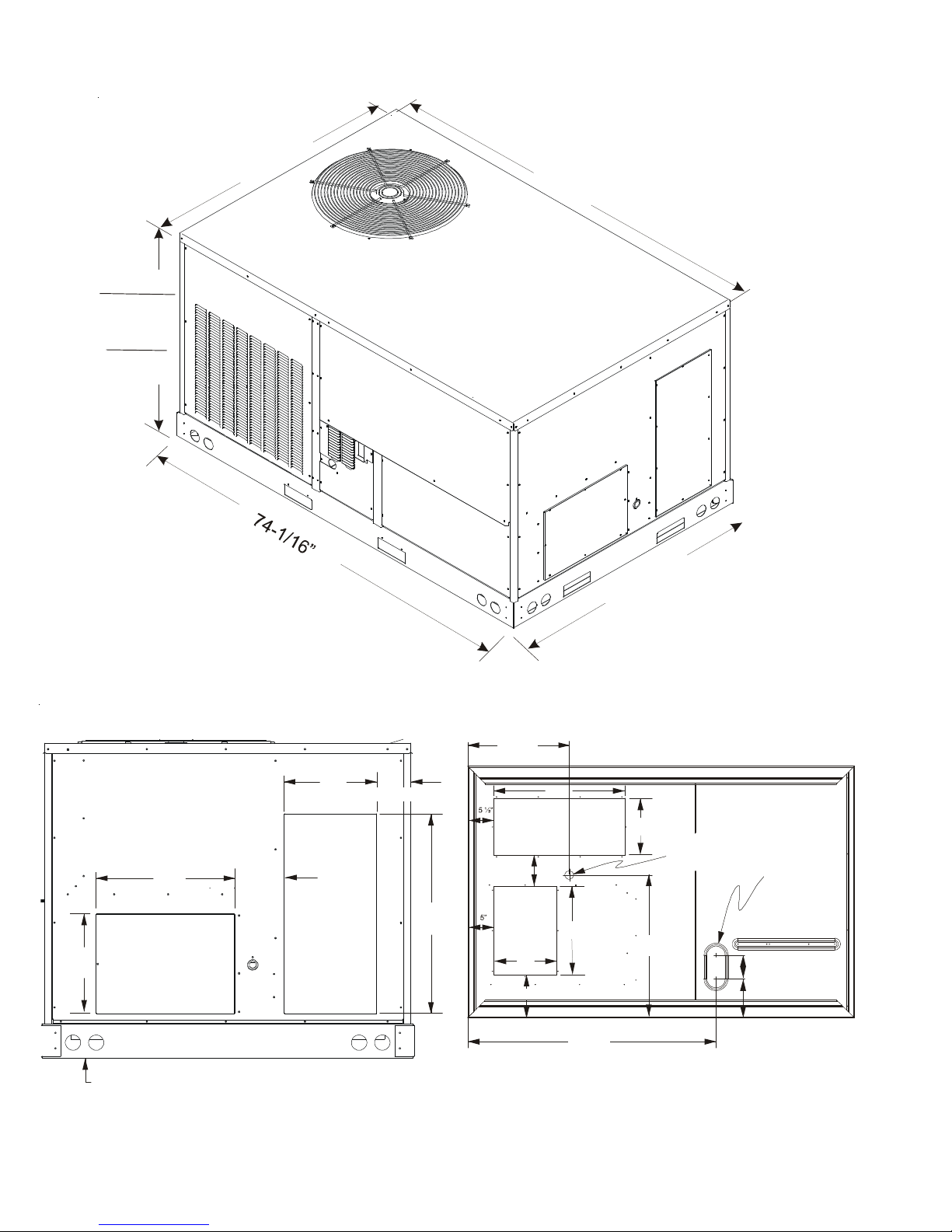
PRODUCT DIMENSIONS
V
”
2
/
1
-
7
4
3
-
5
T
O
N
S
3
8
-
1
3
1
/
6
”
6
T
O
N
S
4
2
-
1
3
/
1
6
”
DCG036-072XXX**XXXA*
7
3
-
1
/
4
”
HORIZONTAL DISCHARGE
17” 7 3/8”
12”
SUPPLY
11”
RETURN
4 7/8”
25”
”
6
1
/
3
-
8
4
ERTICAL DISCHARGE
19 7/16”
25”
RETURN
6 1/4”
SUPPLY
12”
7 13/16”
17”
11”
27 3/8”
DRAIN
THRU CURB
LOCATION
EMBOSS
FOR
THRU THE
BASE
UTILITIES
4 1/2”
7 1/2”
6 1/4”
For horizontal discharge, remove the supply and return duct covers and
place them over the vertical discharge return and supply openings. Install
with insulation facing up, using the longer screws provided in the literature package.
10
47 1/2”
BOTTOM VIEW OF UNIT

CORNER WEIGHTS
A
Corner & Center of Gravity Locations
NOTES:
1. Weights are for belt drive gas unit; no options.
2. Centers of gravity weights are for belt drive gas units
without options.
Provisions for forks have been included in the unit base frame
on three sides. If unit is moved by forklift, no other fork locations are approved.
CAUTION
3 - 6 TONS
DCG036-072XXX**XXXA*
CORNER WEIGHTS
Model
A * Rev
X
(in)Y(in)
Corner Weights ( lbs )
ABCD
DCG036045* 37 30 100 165 100 165
DCG036090* 37 30 100 170 100 170
DCG048090* 37 30 110 180 110 180
DCG048115* 37 30 110 180 110 180
DCG060090* 37 30 113 187 118 192
DCG060140* 37 30 118 192 118 192
DCG072140* 37 30 127 210 127 211
* Weights shown are belt drive with no accessories.
24 1/4”
COMPRESSOR
CONDENSER COIL
RETURN
EVAPORATER COIL
C
B
39”
CENTER OF GRAVITY 3 - 6 TONS
SUPPLY
D
11

PACKAGE GAS SPECIFICATIONS
DCG 0360451DXXA*DCG0 360901DXXXA*DCG04 80901DXXXA*DCG048 1151DXXXA*DCG 0600901D XXXA*DCG06014 01DXXX
COOLING COOLING CA PACITY , BTUH 34,60 0 34,600 45,500 45,500 58,000 58,000
CAPACITY SE ER/EER 13/11.0 13/11. 0 13/11. 3 13/11.3 13/11 .1 13/11. 1
HEATING
CAPACITY LO W HEATING I NPUT / O UTPUT BTUH --- 69,000 / 55 ,200 69,000 / 55,000 86,25 0 / 69,00 0 69,000 / 55, 000 103, 000 / 83,000
UNIT VOLTAG E (NAME PLATE) 2 08-230/1/60 20 8-230/1/60 208 -230/1/60 2 08-230/1/60 20 8-230/1/60 208 -230/1 /60
ELEC TRIC AL UNIT A MPS (TOTAL) 20.6 20.6 24 .1 24.1 35.4 35.4
SPECIFIC ATION
HEATING NUMBER OF BURNERS 244546
SECT ION ORIFICE SIZE NATURAL 43 43 43 4 3 43 43
COMPRESSOR TYP E SCROLL SCROLL SCROLL SCROLL SCR OLL SCRO LL
RATED L OAD AMP S 16.7 16.7 19.9 19.9 26.4 26 .4
CONDENSER HORSEPOWER 1/41/41/41/41/41/4
FAN MOTOR RPM 10 90 1090 1090 1090 109 0 1090
CONDENSER FAN BLAD E DIAMET ER( ") / # OF BLADES 22/4 22/4 22/4 22/4 22/ 4 22/4
CONDENSER FACE AREA - SQ. FT.
COIL NUMBER O F ROWS
EVAPORATOR HORSEPOWER - TY PE 1/3 - DIRE CT DRIVE 1/3 - DIRECT DRIVE 1/2 - DIRECT DRIVE 1/2 - DIRECT DRIVE 1.0 - DI RECT DRIVE 1.0 - DIRECT DR IVE
BLOWER NO. OF SP EEDS PSC - 3 P SC - 3 PSC - 3 PSC - 3 EE M - 5 E EM - 5
MOTOR
EVAPORATOR DIAM ETER X WIDTH (IN CHES) 10 X9 10 X9 10 x 9 10 x 9 11 X 10 11 X 10
BLOWER RATED S CFM COOLING 1200 120 0 1 600 1600 200 0 2 000
EVAPORATOR FACE AREA - SQ. FT.
COIL NUMBER O F ROWS
HEATING PRIM ARY LIMI T SETT ING (° F) 14 0 120 120 1 40 14 0 220
LIMITS AUXILIARY LI MIT SETTI NG (°F) 120 150 150 150 150 150
GENERAL FILTER SIZE - SQ. FT.
INFORMATION DRAI N SIZE (INCHES)
HIGH HEATI NG INPUT / OUTPUT BTUH 4 6,000 / 36,80 0 92 ,000 / 74,000 92,000 / 74, 000 11 5,000 / 92,0 00 92 ,000 / 74,000 1 38,000 / 110 ,400
A.F. U.E. (%) 80 80 80 80 80 80
TEMPERAT URE RISE (° F) HI/LOW 25 - 55 4 0 - 70 / 30 - 60 30 - 60 / 15 - 45 40- 70 / 25 - 55 20 - 50 / 15 - 45 35 - 65 / 25 - 55
MINI MUM CIRC UIT AMP ACITY 25 25 29 29 42 42
MAXIMUM OVERCURRENT PROTECTION
ORIFICE SIZE LP 55 55 55 55 55 55
PRESSURE SWTICH SETTING 0.340.340.340.340.340.34
LOCKED R OTOR AMPS 79 79 109 1 09 134 134
RATED L OAD AMP S 1.40 1.40 1.40 1.40 1.40 1.4 0
LOCKED R OTOR AMPS 2.9 2 .9 2. 9 2. 9 2 .9 2. 9
NOMINAL C FM 3,800 3,800 3,800 3, 800 3,800 3,800
FI NS PE R INC H
FULL LO AD AMPS 2.5 2.5 2. 9 2.9 7 .6 7. 6
LOCKE D ROTO R AMPS -- -- 5 5 --- - --
MOTOR SPEED TAP - COOLING LOW SPE ED LOW SPEED Medium Medium T4 T4
RPM 890 890 1 000 10 00 105 0 1 050
MAX EXTERNAL STATIC PRESS ("w.c.) 0.5 0.5 0.6 0.6 0.9 0.9
FI NS PE R INC H
ROLLOUT L IMIT SET TING (°F) 350 350 350 350 350 350
EXPA NSION D EVICE
REFRIGERANT CHARGE R-410A (Oz.)
POWER SUPPLY CONDUIT HOLE SIZE (") 1.97" 1.97" 1.97" 1.97" 1.97" 1.97"
KNOCKOU TSIZE (" ) 1.125 1.125 1.125 1. 125 2.56" 2.5 6"
LOW VOLTAG E CONDUIT HO LE SIZE (") 1/2" 1/ 2" 1/ 2" 1/2 " 1/ 2 1/2
LOW PRESS URE SWIT CH (OPEN/CLO SE-PSIG) 22/50 22 /50 22/ 50 22/5 0 55/95 55/ 95
HIGH PRESSURE SWITCH (OPENS-P SIG) 660 66 0 660 660 660 660
SHIPPING WEIGHT LBS.
OPERATIN G WEIGHT LBS.
(2)
40 40 45 45 60 60
17 17 17 17 1 2.5 12 .5
111122
24 24 24 24 27 27
5.45.4 7 7 7.87.8
334444
16 16 16 16 16 16
(1) 24 "X 24" x 2" (1) 24"X 24" x 2" (4) 14" X 2 0" x 2" (4) 14" X 20" x 2" (4) 1 4" X 20" x 2" (4) 14" X 20" x 2"
3/4" 3/4" 3/ 4" 3/ 4" 3 /4" 3/ 4"
Orifice (0.068) Orifice (0.068) Orifice (0.076) Orifice (0.076) Orifice (0.086) Orifice (0.086)
83 85 103 1 03 100.8 100 .8
550 560 600 605 635 645
525 535 575 580 610 620
DCG036-060XXX1DXXXA*
A*
(1) Units installed in Canada are certifed only to 4500 feet.
(2) Maximum Overcurrent Protection Device: MUST use Time Delay Fuse or HACR type Circuit Breaker of the same size as noted.
IMPORTANT: While this data is presented as a guide, it is important to electrically connect the unit and properly size wires and fuses/circuit breakers in
accordance with the National Electrical Code and/or all local codes.
12

PACKAGE GAS SPECIFICATIONS
DCG0 360453DXXXA*DCG03 60903DX XXA*DCG 0480903 DXXXA*DCG0 481153DXXXA*DCG06 00903DX XXA*DCG 0601403 DXXX
COOLING CO OLING CA PACITY, BT UH 34,600 34,600 4 5,500 45,500 58,000 58 ,000
CAPACITY SEER/ EER 13/11 .0 13/11. 0 13/1 1.3 13/11 .3 13/11. 1 13/1 1.1
HEATING HIGH HE ATING INPUT / 0UTP UT BTUH 46 ,000 / 36,800 92,0 00 / 74,000 92,00 0 / 74,000 115,000 / 92,000 92,0 00 / 74,000 138,000 / 110,4 00
CAPACITY
UNIT VOLT AGE (NAMEPLA TE) 20 8-230/3/60 208-23 0/3/60 208-230 /3/60 208-2 30/3/60 2 08-230/3/60 20 8-230/3/60
ELEC TRIC AL
SPECIFICAT ION MINIMUM CIRCUIT A MPACITY 17 17 2 1 21 29 29
HEATING NUMB ER OF BU RNERS 2 4 4 5 4 6
SECT ION
COMPRESSOR TYPE SCROLL SCROLL SC ROLL SCROLL SCROLL SCROLL
RATED L OAD AMP S 10.4 10.4 13.1 13 .1 16 16
CONDENSER HORSEPOWER 1/41/41/41/41/41/4
FAN MOTOR RPM 1090 1090 10 90 1090 1090 109 0
CONDENSER FAN
CONDENSER FACE AREA - SQ. FT.
COIL NUMB ER OF ROW S
EVAPORATOR HORSEP OWER - TY PE - STANDARD 1/3 - DIRECT DRIV E 1/3 - DIRECT DR IVE 1/2 - DIRE CT DRIVE 1/2 - DIR ECT DRIVE 1.0 - DIRECT DR IVE 1 .0 - DIREC T DRIV E
BLOWER NO. OF SPEEDS PSC - 3 PSC- 3 PSC - 3 PSC - 3 EEM - 5 EEM - 5
MOTO R RATED L OAD AMP S 2.5 2.5 2.87 2. 87 7.6 7.6
EVAPORATOR
BLOWER RATE D SCFM COO LING 1200 1200 16 00 1600 2000 200 0
EVAPORATOR FACE AREA - SQ. FT.
COIL
HEATING
LIMITS AUXILIAR Y LIMIT S ETTING (°F) 120 1 50 150 150 150 15 0
GENERAL FILTER SIZE
INFORM AT ION DRAIN S IZE (INCH ES)
LOW HEA TING INPU T / OUTPUT B TUH --- 69,000 / 55,00 0 69,00 0 / 55,000 86,250 / 69,000 6 9,000 / 55,0 00 10 3,000 / 83,00 0
STEADY STATE EFFY % 80 80 80 80 80 80
TEMPERA TURE RISE (° F) HI/LOW 25 - 55 / 40 - 70 / 30 - 60 30 - 60 / 1 5 - 45 40-70 / 25 -55 20 - 50 / 15 - 4 5 35 - 65 / 25 - 55
UNIT AMP S (TOTAL) 14.4 14. 4 17.4 17.4 25 25
MAXIMUM OVERCURRENT PROTECTION
ORIFICE SIZE NATURAL 434343434343
ORIFICE SIZE LP 55 55 55 55 55 55
PRESSURE S WITCH S ETTIN G 0.34 0.3 4 0.34 0.34 0.34 0.34
LOCKED R OTOR AMPS 73 73 83.1 83.1 1 10 110
RATED L OAD AMP S 1.4 1.4 1.40 1. 40 1.4 1. 4
LOCKED R OTOR AMPS 2.9 2.9 2.9 2 .9 2.9 2.9
BLADE DIA METER( ") / # OF BLADE S 22/4 22/ 4 22/4 22/4 22/ 4 2 2/4
NOMINAL C FM 3,800 3,800 3 ,800 3, 800 3,800 3,800
FINS PER INCH
LOCKED ROTOR AMPS 3.3 3.3 5 5 -- ---
MOTOR S PEED TAP - CO OLING LOW SPEED LOW SPEED M edium M edium T4 T4
RPM 890 8 90 10 00 1000 1050 105 0
DIAMET ER X WIDT H (INCHES) 10 x 9 10 x 9 10 X 9 10 X 9 11 X 10 11 X 10
MAX EXTERNA L STATIC PRES S ("w.c.) 0 .5 0.5 0.5 0 .5 0.9 0.9
NUMBE R OF ROWS
FINS PER INCH
PRIMAR Y LIMIT SET TING (°F) 140 120 12 0 140 1 40 220
ROLLOUT LIMIT SE TTING (° F) 350 3 50 35 0 350 3 50 35 0
EXPA NSION D EVICE
REFRI GERANT CH ARGE R-41 0A (Oz .)
POWER SUP PLY CONDUIT HO LE (") 1.125 1.125 1 .125 1. 125 1.12 5 1.125
LOW VOLTAG E CONDUIT HOLE 1 /2" 1/2" 1/ 2" 1 /2" 1/2 " 1/2"
LOW PRESSURE SWITC H ( OPEN/CLO SE-PSIG) 22/50 22/50 2 2/50 22 /50 55/95 55/95
HIGH PR ESSU RE SWITCH (OPENS-PSIG ) 660 660 66 0 660 6 60 660
SHIPPING WEIGHT LBS.
OPERATING WEIGHT LBS.
(2)
25 25 3 0 30 40 40
17 18 1 7 17 12. 5 1 2.5
111122
24 22 2 4 24 27 27
5.45.47.07.07.87.8
334444
16 16 1 6 16 16 16
(1) 24"X 24" x 2" (1) 24"X 24" x 2" (4) 14"X 20" x 2" (4) 14"X 20" x 2" (4) 14"X 20" x 2" (4) 14"X 20" x 2"
3/4" 3/4" 3/4" 3/4" 3/4" 3/4"
Ori fice (0. 072) Or ifice ( 0.068) Orifice (0.076 ) Orif ice (0.0 76) ORIFI CE (0.086) ORIFICE (0.086)
83 83 103 103 100 .8 100.8
550 5 60 600 605 6 35 645
525 5 35 575 580 6 10 620
DCG036-060XXX3DXXXA*
A*
(1) Units installed in Canada are certifed only to 4500 feet.
(2) Maximum Overcurrent Protection Device: MUST use Time Delay Fuse or HACR type Circuit Breaker of the same size as noted.
IMPORTANT: While this data is presented as a guide, it is important to electrically connect the unit and properly size wires and fuses/circuit breakers in
accordance with the National Electrical Code and/or all local codes.
13

PACKAGE GAS SPECIFICATIONS
DCG0360453BX XXA*DCG036 0903BX XXA*DC G0480 903BXXXA*DCG048 1153BXXXA*DCG060 1403BXX XA*DC G07214 03BXXX
COOL ING
CAPACITY
HEATING
CAPACITY
UNIT
ELE CTRIC AL
SPECI FICATION
HEATING
SEC TION
COMPRE SSOR
CONDE NSER
FAN MOTOR
CONDE NSER FAN
CONDE NSER
COIL
EVAPORATO R
BLOW ER
MOTOR
EVAPORATO R
BLOW ER
EVAPORATO R
COIL
HEATING
LIMITS
GENERAL
INFORM ATION
COO LING CA PACITY , BTUH 34,600 34,60 0 45,500 45,5 00 58,000 71, 000
SE ER/EER 13/11 .0 13 /11.0 13/11 .3 13 /11.3 13/11.1 11.0
H IGH HEATI NG INPU T / OUTP UT BTUH 46,0 00 / 36,800 92,00 0 / 74,0 00 92 ,000 / 74 ,000 115,0 00 / 92, 000 138,00 0 / 110,4 00 138, 000 / 11 0,400
LO W HEA TING IN PUT / OUT PUT BT UH --- 69,000 / 55,000 69 ,000 / 55 ,000 86,2 50 / 69, 000 103,00 0 / 83,0 00 103 ,000 / 83 ,000
STEADY STATE EFFY % 808080 808080
TEM PERATURE RISE (°F) H I/LOW 25 - 55 40 - 7 0 / 30 - 60 3 0 - 60 / 15 - 45 40-70 / 25-55 35 - 6 5 / 25 - 55 3 5 - 65 / 25 - 55
VO LTAGE (NA MEPLATE ) 208-2 30/3/60 2 08-230/3 /60 20 8-230/3/60 208-2 30/3/60 208- 230/3/6 0 208- 230/3/60
UNIT AMPS (TOTAL) 15.715.718.318.321.222.4
MIN IMUM C IRCUIT AMPACI TY 18 1 8 22 22 25 31
MAXIM UM OVERCURRE NT PROTEC TION
N UMBER OF BUR NER S 2 4 4 5 6 6
ORIFICE SIZE NATURAL 434343434343
ORI FICE SIZE LP 55 55 55 55 55 55
PRE SSURE S WITCH S ETTING 0. 34 0. 34 0 .34 0.3 4 0.34 0. 34
TYP E SCRO LL SCRO LL SCR OLL SCROLL SCROLL SCROL L
RATE D LOAD AMP S 10.4 10.4 1 3.1 13 .1 16 16
LO CKED ROTO R AMPS 73 7 3 83.1 83 .1 11 0 110
HORSEPOWER 1/41/4 1/41/41/41/4
R PM 1090 10 90 109 0 1 090 10 90 109 0
R ATED LOAD A MPS 1. 4 1.4 1.40 1.4 0 1.4 1. 4
LOCKED ROTOR AMPS 2.92.9 2.92.92.94.0
BLA DE DIAMET ER( ") / # OF BLA DES 22 /4 22/4 2 2/4 22 /4 22/4 22 /4
N OMINA L CFM 3,8 00 3,800 3 ,800 3,800 3 ,800 3,800
FAC E AREA - SQ. F T.
NUMBER OF ROWS
FI NS PE R INCH
HORSEPOWER - TYPE - STANDARD
NO. OF S PEEDS
R ATED LOAD A MPS 3. 8 3.8 3.8 3. 8 3.8 5
LO CKED RO TOR AM PS 10 .9 10.9 1 0.9 10 .9 24 18
MOTOR SPEED TAP - COOLING --- --- --- --- --- ---
R PM 1725 17 25 172 5 1 725 17 25 172 5
DI AMETER X WIDTH (INCH ES) 11 X 10 11 X 10 11 x 1 0 1 1 x 10 11 X 10 11 X 10
R ATED SCFM C OOLING 1200 1200 1600 1 600 20 00 2 400
MAX E XTERNAL ST ATIC PRESS ("w.c.) 0.7 0.7 1.0 1.0 1.0 1 .0
FAC E AREA - SQ. F T.
NUMBER OF ROWS
FI NS PE R INCH
PRIM ARY LI MIT SET TING (° F) 140 120 140 140 22 0 140
AUX ILIARY LI MIT S ETTI NG (°F) 120 150 145 150 14 5 150
R OLLO UT LIMIT SETT ING (°F) 350 350 350 350 350 350
FI LTER SIZE
D RAIN SI ZE (IN CHES )
EXPANSI ON DEVICE
REFRIG ERANT CHA RGE R-410 A (Oz.)
PO WER SUP PLY C ONDUIT H OLE (") 1 .125 1.12 5 1.125 1.1 25 1 .125 1.125
LO W VO LTAGE C ONDU IT HOLE 1/ 2" 1/2" 1 /2" 1/ 2" 1/2" 1 /2"
LO W PRE SSURE SWI TCH (OPEN/CL OSE-PSIG) 2 2/50 22/50 22/50 22/50 55/9 5 55/95
HI GH PRESSU RE SWITCH (OP ENS-PSIG ) 660 660 660 660 66 0 660
SHIP PING WEIGHT LBS.
OP ERATIN G WEIGH T LBS . 525 535 575 580 620 675
(2)
25 2 5 30 30 40 45
17 1 8 17 17 12.5 19
111122
24 2 2 24 24 27 27
1.0 - STD STAT IC
BELT DRIVE
11
5.45.4 7.87.87.87.8
334444
16 1 6 16 16 16 16
(1) 24" X 24" x 2 " (1) 24"X 24" x 2" (4) 14"X 20" x 2" (4 ) 14"X 20" x 2" (4) 14 "X 20" x 2" (4 ) 14"X 20 " x 2"
3/4" 3/4 " 3 /4" 3/4" 3/4" 3/4"
Orifi ce (0.0 72) Orifi ce (0.06 8) O rifice (0. 076) O rifice (0. 076) O RIFICE (0 .086) O RIFICE (0 .094)
85 8 3 105 103 1 00.8 146
550 560 600 605 645 700
1.0 - STD STATIC
BELT DR IVE
DCG036-072XXX3BXXXA*
A*
1.0 - STD S TATIC
BELT DRIVE
1111
1.0 - ST D STAT IC
BELT D RIVE
1.0 - STD STATIC
BELT DRIVE
1.5 - ST D STATIC
BELT DRIVE
(1) Units installed in Canada are certifed only to 4500 feet.
(2) Maximum Overcurrent Protection Device: MUST use Time Delay Fuse or HACR type Circuit Breaker of the same size as noted.
IMPORTANT: While this data is presented as a guide, it is important to electrically connect the unit and properly size wires and fuses/circuit breakers in
accordance with the National Electrical Code and/or all local codes.
14

PACKAGE GAS SPECIFICATIONS
(
DCG036 0454BXXXA*DCG0 360904BXX XA*DCG04 80904BXXXA*CPG04811 54BXXXA*DCG06 00904BXXXA*DCG060 1404BXXXA*DCG0 721404BXXX
COOL ING COOLING CAPACIT Y, BTUH 34, 600 34, 600 45,5 00 45,500 58,000 5 8,000 71, 000
CAPACI TY SEER/ EER 13/11.0 13/11. 0 13/11.3 13/11.3 13/11. 1 13/11.1 11 .0
HEATI NG HIGH HEAT ING INPUT / OUTPUT BTUH 4 6,000 / 3 6,800 92, 000 / 74 ,000 9 2,000 / 74,000 115,000 / 92,00 0 92,0 00 / 74,0 00 138,000 / 110,4 00 1 38,000 / 110,400
CAPACI TY LOW HEATING INPUT / OU TPUT BTUH --- 6 9,000 / 55,0 00 69,00 0 / 55,000 86 ,250 / 69,000 69, 000 / 55,0 00 10 3,000 / 83,0 00 103,000 / 83,000
UNIT VOLTA GE (NAMEPLA TE) 460/3/ 60 460/ 3/60 460/3/ 60 4 60/3/60 460/ 3/60 460/3/60 460/3/ 60
ELE CTR IC AL UNIT AMPS (T OTAL) 8.5 8.5 8.8 8 .8 10.5 10.5 13.4
SPECIFICATION MINI MUM CIRCU IT AMPACIT Y 1 0 10 1 0 10 13 1 3 16
HEATI NG NUMBER OF BURNERS 2 4 4 5 4 6 6
SEC TIO N ORIFICE SIZE NATURAL 43434343 434343
COMPRE SSOR
RATED LOAD AMPS 5.8 5.8 6.1 6.1 7.8 7.8 9.7
CONDE NSER HORSEPOWER 1/41/41/41/41/41/41/3
FAN MOTOR
CONDE NSER FAN
CONDE NSER FACE AREA - SQ. FT.
COIL NUMBE R OF ROWS
EVAPORATOR HORSEPOWER - T YPE
BLOW ER NO. OF SPEEDS 1 1 1 1 1 1 1
MOTO R RATED LOAD AMPS
EVAPORATOR DIAME TER X WIDT H (INCHES ) 11 X 10 11 X 10 1 1 X 10 11 X 1 0 11 X 10 11 X 10 11 X 10
BLOW ER RATE D SCFM COOLI NG 12 00 1200 1600 1600 2 000 2000 2,400
EVAPORATOR FACE AREA - SQ. FT.
COIL NUMBE R OF ROWS
HEATI NG PRI MARY L IMIT SETT ING (°F ) 14 0 120 1 40 14 0 160 220 140
LIMITS AUX ILIARY LIM IT SETT ING (°F) 12 0 150 1 45 15 0 145 145 150
GENERAL FILTER SIZE
INFORMATI ON DRAIN SIZE (INCHES)
A.F.U.E. (%) 80808080808080
TEMPERA TURE RIS E (°F ) HI/LOW 25 - 55 40 - 70 / 30 - 60 30 - 6 0 / 15 - 4 5 40-70 / 25 -55 20 - 50 / 15 - 4 5 35 - 65 / 25 - 55 30 - 60 / 15 - 45
MAXIMUM OVERCURRENT PROTECTION
ORIFICE SIZ E LP 55 55 5 5 55 55 5 5 55
PRESSURE SWTICH SETT ING 0. 34 0.34 0.3 4 0.34 0.3 4 0.34 0. 34
TYPE SCROLL SCROL L SCROLL SCROL L SCROLL SCRO LL S CROLL
LOCKED R OTOR AMPS 38 38 41 41 52 52 62
RPM 890 890 8 90 890 1090 1090 1075
RATED L OAD AMP S 0.8 0 .8 0.80 0. 80 0.8 0.8 1.2
LOCKED R OTOR AMPS 1.7 1 .7 1. 7 1 .7 1. 7 1.7 2.3
BLADE D IAMETER( ") / # OF B LADES 22/4 22/ 4 22/4 22/ 4 22/4 22/4 22/4
NOMINAL C FM 3,800 3, 800 3, 800 3, 800 3,8 00 3,800 4,3 00
FINS PER INCH
LOCKED R OTOR AMPS 10.9 10.9 10.9 1 0.9 13 1 3 12
MOTOR SPEED TAP - COOLING --- --- -- - --- -- -' ---' ---
RPM 1725 1725 1725 172 5 1 725 1725 1725
MAX EXTERNAL STATIC PRESS ("w.c.) 0.7 0.7 1.0 0.8 1.0 1.0 1.0
FINS PER INCH
ROLLOUT L IMIT SE TTING (° F) 350 350 3 50 35 0 350 350 350
EXPA NSION DEVIC E
REFRIGERANT CHARGE R-410A (Oz.)
POWER SUP PLY CONDUIT HO LE (") 1 .125 1.1 25 1.12 5 1.97" 1.125 1.125 1. 125
LOW VOLTAG E CONDUIT HOLE 1/ 2" 1/2" 1/2 " 2.56" 1/ 2" 1/2" 1/2"
LOW PRES SURE SWITCH ( OPEN/CLOSE - 2 2/50 22 /50 22/5 0 22/50 55/ 95 55/95 55 /95
HIGH P RESSURE SWI TCH (OPE NS-PSIG) 66 0 660 660 660 660 66 0 660
SHI PPING W EIGH T LBS.
OPERATI NG WEIGHT LBS. 525 535 5 75 58 0 610 620 675
15 15 15 15 20 2 0 25
17 18 17 17 12 .5 12.5 19
1111222
24 22 24 24 27 2 7 27
1.0 - STD STATIC
BELT DRIVE
1.9 1 .9
5.4 5 .4 7.0 7.0 7.8 7.8 8 .9
3344444
16 16 16 16 16 1 6 16
(1) 24 "X 24" x 2" (1) 24"X 24" x 2 " (4) 14"X 20" x 2" (4) 14"X 20" x 2" ( 4) 14" X 2" x 2" (4) 14" X 20" x 2" (4) 16 " X 20" x 2"
3/4" 3/4" 3/4 " 3/4" 3/ 4" 3/4" 3 /4"
ORIFIC E (0.068) ORI FICE (0.06 8) O rifice (0. 076) Or ifice (0. 076) O RIFICE (0.086 ) ORIFIC E (0.086) ORIF ICE (0.09 4)
83 85 103 103 100 .8 1 00.8 146
550 560 6 00 60 5 630 645 700
1.0 - STD STAT IC
BELT DRIVE
1.0 - ST D STATIC
DCG036-072XXX4BXXXA*
BEL T DR IVE
1.9 1 .9
1.0 - STD ST ATIC
BELT DRIVE
1.0 - STD STAT IC
BELT DRIV E
1.9 1.9 2 .5
1.0 - STD STATIC
BELT DRI VE
A*
1.5 - STD ST ATIC
BELT DRIVE
(1) Units installed in Canada are certifed only to 4500 feet.
(2) Maximum Overcurrent Protection Device: MUST use Time Delay Fuse or HACR type Circuit Breaker of the same size as noted.
IMPORTANT: While this data is presented as a guide, it is important to electrically connect the unit and properly size wires and fuses/circuit breakers in
accordance with the National Electrical Code and/or all local codes.
15

PACKAGE GAS SPECIFICATIONS DCG036-072XXX7BXXXA*
DCG03 60907BX XX
A*
COOLING C OOLING CAPACITY , BTUH 35,0 00 45,50 0 58,000 71, 000
CAPACITY SE ER/EE R 13 /11.0 13/1 1.3 13 /11.1 11.0
HEATING HIGH HEATING INPUT / O UTPUT BTUH 92,000 / 74,000 11 5,000 / 92,0 00 138,000 / 110,400 138, 000 / 110,40 0
CAPACITY LO W HEATING INPUT / OUTP UT BTUH 69,000 / 55,000 86,25 0 / 69,000 103,000 / 83,00 0 103 ,000 / 83 ,000
A.F.U.E. (%) 808080 80
T EMPERATURE R ISE (°F) HI/LOW 40 - 70 / 30 - 6 0 40 - 70 / 25-55 3 5 - 65 / 25 - 55 35 - 65 / 25 - 55
UNIT VO LTAGE (NA MEPLATE ) 575/3/6 0 575/ 3/60 575/3/60 575/3/60
ELECTRICAL UNIT AMPS (TOTAL)
SPECIFICATION MINIMUM CIRCU IT AMPACITY 7.7 8 10 10
HEATING NU MBER OF BU RNER S 4 5 6 6
SECT ION ORIFICE SIZE NATURAL 43 4 3 43 43
COMPRESSO R T YPE SCROLL SCROLL SCROLL SCROLL
RATED LOAD AMPS
CONDENSER HORSEPOWER
FAN MOTOR RPM 1075 10 75 1075 1075
CONDENSER FAN
CONDENSER FACE AREA - SQ. FT.
COIL
EVAPORATOR HORSEPOWER - TYPE
BLOWER NO. OF SPEEDS 1 1
MOTOR RATED LOAD AMPS
EVAPORATOR D IAMETE R X W IDTH (INCHES) 1 1 X 10 11 X 10 11 X 10 11 X 10
BLOWER RAT ED SCFM COOLING 1 200 1600 2000 2400
EVAPORATOR FACE AREA - SQ. FT.
COIL NUMBER OF ROWS
HEATING PRIMAR Y LIMI T SE TTING (°F ) 120 140 220 140
LIMITS AUXILIARY LIMIT SETTI NG (°F) 150 150 145 150
GENERAL FILTER SIZE
INFORMATION D RAIN SIZE (INCHES)
MAXIM UM OVERCURRE NT PROTECTION
OR IFICE SI ZE L P 55 55 55 55
PRESSURE SWTICH SETTING 0.34 0.34 0.34 0.34
LO CKED ROTO R AMPS 36.5 33 38.9 38.9
RATED LOAD AMPS
LO CKED ROTO R AMPS 1.61 1.61 1.61 2.3
BLADE DIAMETER( ") / # OF BLADES
NO MINAL CF M 3,800 3,80 0 3,800 3,800
NUMBER OF ROWS
FINS PER INCH
LOCKED RO TOR AMPS 10.9 10.9 11 12
MOTOR SPEED TAP - COOLING --- ---
RPM 1 725 1725 1725 1725
MAX EXTERNAL STATIC PRESS ("w. c.) 0.7 0.8 1.0 1.0
FINS PER INCH
RO LLOUT LIMIT SETT ING (°F) 350 350 35 0 350
EXPANSI ON DEVICE
REFRI GERANT CHARG E R-410A (Oz.)
POWER SUPPLY CONDUIT HOLE (") 1.125 1.125 1.125 1.125
LOW VOLTAGE CONDUIT HOLE 1/2" 1/2" 1/2" 1/2"
LOW PRESSURE S WITCH (O PEN/CLO SE-PSIG) 22/50 22/50 5 5/95 55/95
H IGH PRES SU RE SWIT CH (OP ENS- PSIG ) 660 6 60 66 0 660
SHIPPING WEIGHT LBS.
OP ERAT ING WE IGHT LBS . 535 580 620 675
(2)
6.7
15
3.8
1/4
0.58
22/4
13 17 12.5 19
2
16 24 27 27
1.5 - STD STATIC BELT
DRIVE
2.3
5.4 7.8 7.8 7 .8
3444
16 16 16 16
(1) 24 X 24 x 2 (4 ) 14 X 20 x 2 (4) 14" X 20" x 2" ( 4) 14" X 2 0" x 2"
3/4" 3/4 " 3/4" 3 /4"
ORI FICE (0.068 ) ORIFICE (0. 076) ORIFICE (0.086) OR IFICE (0.09 4)
ORI FICE (0.053) 1 10 100.8 146
560 605 645 700
DCG048 1157BXXX
A*
7.3
15
4.4
1/4
0.58
22/4
122
1.5 - STD STATIC BELT
DRIVE
2.3
DCG0601407BXX X
A*
8.58 8.58
15 15
5.7 5.7
1/4 1/4
.58 .58
22/4 22/4
1.5 - STD STATIC BELT
DRIVE
NA 1
2.3 2.3
--- ---
DCG0 721407BXX X
A*
1.5 - STD ST ATIC BELT
DRIVE
(1) Units installed in Canada are certifed only to 4500 feet.
(2) Maximum Overcurrent Protection Device: MUST use Time Delay Fuse or HACR type Circuit Breaker of the same size as noted.
IMPORTANT: While this data is presented as a guide, it is important to electrically connect the unit and properly size wires and fuses/circuit breakers in
accordance with the National Electrical Code and/or all local codes.
16
 Loading...