

Page 1

OPERATING
MANUAL
ON/OFF
MODEFAN
POWERFUL
SENSE
LED
TIMER
ON
CANCEL CLOCK
TEMP
CANCEL
SWING
SLEEPQUIET
ECO+
OFF
Operating Manual
Handset Wireless
Mode D’emploi
Combiné sans fil
Bedienungsanleitung
Drahtloses Handgerät
Manuale Di Funzionamento
Ricevitore senza fili
Manual De Instrucciones
Auricular Inalámbrico
Руководство По Зксплуатации
Беспроводное Дистанционное Управление
Kullanım Kılavuzu
Kablosuz Kulaklık
English
Français
Deutsch
Italiano
Español
Pycckий
Türkçe
OM-BRC52B-1114(0)-DAIKIN
Part No.: R08019041828
Page 2

Page 3

BRC52B61/62/63 Remote Controller Indication /
Indication De Télécommande BRC52B61/62/63 /
BRC52B61/62/63-Remote-Controller-Anzeige / Indicazioni
Telecomando BRC52B61/62/63 / Indicación Del Mando A
Distancia BRC52B61/62/63 /
Пульт Дистанционного
Управления BRC52B61/62/63 Индикация /
BRC52B61/62/63 Uzaktan Kumanda Göstergesi
1
2
ON/OFF
16
15
11
3
5
4
7
POWERFUL
TEMP
SWING
MODEFAN
SLEEPQUIET
13
6
12
9
SENSE
LED
TIMER
ON
CANCEL CLOCK
ECO+
OFF
CANCEL
14
8
10
i
Page 4

HOW TO MOUNT ONTO THE WALL / COMMENT INSTALLER SUR LE MUR /
ANBRINGEN DER FERNSTEUERUNG AN DER WAND / COME FISSARE L’ASTUCCIO
DEL TELECOMANDO ALLA PARETE / MONTAJE SOBRE LA PARED / КАК
УСТАНОВИТЬ НА СТЕНУ / DUVARA NASIL YERLEŞTİRİLİR
ON/OFF
POWERFUL
LED
ON
CANCEL CLOCK
TEMP
SWING
MODEFAN
SLEEPQUIET
ECO+
SENSE
TIMER
OFF
CANCEL
ON/OFF
POWERFUL
LED
ON
CANCEL CLOCK
TEMP
SWING
MODEFAN
SLEEPQUIET
ECO+
SENSE
TIMER
OFF
CANCEL
TO INSERT BATTERIES (AAA.R03) / INTRODUIRE LES PILES (AAA.R03) /
EINSETZEN DER BATTERIEN (AAA.R03) / INSERIMENTO DELLE BATTERIE (AAA.
R03) / INSERTE LAS PILAS (AAA.R03) / УСТАНОВКА БАТАРЕЙ (AAA.R03) /
PİLLER NASIL TAKILIR (AAA.R03)
ii
Page 5

REMOTE CONTROLLER LOSS PREVENTION WITH BALL CHAIN (OPTIONAL) /
PRÉVENTION CONTRE LA PERTE DE LA TÉLÉCOMMANDE PAR CHAÎNETTE À
BOULES (FACULTATIF) / DIE FERNBEDIENUNG IST DURCH EINE KUGELKETTE VOR
VERLUST GESICHERT (OPTIONAL) / PREVENZIONE PERDITA TELECOMANDO
CON CATENA A SFERA (OPZIONALE) / PREVENCIÓN DE PÉRDIDA DEL CONTROL
REMOTO CON CADENA DE BOLAS (OPCIONAL) / ПРЕДОТВРАЩЕНИЕ
ПОТЕРИ ПДУ С ПОМОЩЬЮ ШАРИКОВОЙ ЦЕПИ (ДОПОЛНИТЕЛЬНОЕ
ОБОРУДОВАНИЕ) / ZİNCİRLE UZAKTAN KUMANDANIN KAYBOLMASININ
ÖNLENMESİ (İSTEĞE BAĞLI)
Remote controller
Télécommande
Fernbedienung
Telecomando
Control Remoto
Пульт дистанционного управления
Uzaktan kumanda
Screw
Vis
Schraube
Vite
Tornillo
Винт
Vida
Wall attachment screw
Vis de fixation murale
Schraube für Wandbefestigung
Vite fissaggio a parete
Tornillo de instalación en pared
Винт настенного крепления
Duvar ba¤lant› vidas›
Ball chain (350mm)
Chaînette à boules (350 mm)
Kugelkette (350mm)
Catena a sfera (350mm)
Cadena de bolas (350mm)
Шариковая цепь (350 мм)
Zincir (350mm)
Holder Support
Soutien de détenteur
Houder ondersteuning
Supporto Holder
Apoyo Holder
Поддержка держатель
Tutucu desteği
iii
Page 6

Installation
1.
Match the ring at the end of the ball
chain with the screw hole on the back
of the remote controller and secure it
with the screw.
2.
Attach the holder and the ball chain
as above at the position where signals
from the remote controller can be
received easily.
3.
Pass the ball chain through the back
of the holder and match the ring at
the end of the ball chain to the upper
hole of the holder. Fix the holder to
the wall by putting through 2 screws
across it.
Installation
1.
Faites correspondre l’anneau de
l’extrémité de la chaînette à boules
avec le trou de vis situé au dos de
la télécommande et fixez-le à l’aide
de la vis.
2.
Fixez le support et la chaînette à boules
comme ci-dessus, dans une position
permettant une réception facile des
signaux de la télécommande.
3.
Passez la chaînette à boules à l’arrière
du support et faites correspondre
l’anneau de l’extrémité de la chaînette
à boules avec le trou supérieur du
support. Fixez le support au mur à
l’aide de 2 vis.
Installation
Legen Sie den Ring am Ende der
1.
Kugelkette auf die Schraubbohrung
an der Rückseite der Fernbedienung
und befestigen Sie ihn mit der
Schraube.
Montieren Sie die Halterung und
2.
die Kugelkette wie oben gezeigt
an der Stelle, an der Signale von
der Fernbedienung gut empfangen
werden können.
3.
Führen Sie die Kugelkette durch die
Rückseite der Halterung und legen
Sie den Ring am Kettenende auf
das obere Loch in der Halterung.
Befestigen Sie die Halterung mit 2
Schrauben an der Wand.
Installazione
1.
Far combaciare l’anello all’estremità
della catena a sfera con il foro della
vite sul retro del telecomando e fissare
bene con la vite.
2.
Fissare il supporto e la catena a sfera
al di sopra del punto in cui possono
essere ricevuti facilmente i segnali dal
telecomando.
3.
Far passare la catena a sfera attraverso
il retro del supporto e far combaciare
l’anello all’estremità della catena con
il foro superiore del supporto. Fissare
il supporto alla parete mettendo 2 viti
attraverso di esso.
iv
Page 7

Instalación
Una el anillo del final de la cadena
1.
de bolas con el agujero del tornillo
de la parte trasera del control remoto
y fíjelo con el tornillo.
Coloque el soporte y la cadena
2.
de bolas, como indica la imagen
superior, en una posición en que las
señales del control remoto se puedan
recibir con facilidad.
Pase la cadena de bolas por la parte
3.
trasera del soporte y una el anillo
del final de la cadena de bolas con
el agujero superior del soporte. Fije
el soporte en la pared colocando 2
tornillos a través del soporte.
Монтаж
Соотнесите кольцо на конце
1.
шариковой цепи с винтовым
отверстием в задней части
пульта дистанционного
управления и закрепите его с
помощью винта.
Прикрепите держатель и
2.
шариковую цепь, как показано
выше, в положении, где
обеспечивается легкий прием
сигнала ПДУ.
Проденьте шариковую цепь
3.
через заднюю часть держателя
и соотнесите кольцо на конце
шариковой цепи с верхним
отверстием держателя.
Прикрепите держатель к стене
с помощью 2 винтов.
MontajMontaj
Zincirin sonundaki halkayla
1.
uzaktan kumandan›n arkas›ndaki
vida deli¤ini efllefltirin ve vidayla
sabitleyin.
Tutucu ve zinciri uzaktan
2.
kumandadan gelen sinyallerin
kolayca al›nabilece¤i yerin üzerine
yerlefltirin.
Zinciri tutucunun arkas›ndan
3.
geçirin ve zincirin sonundaki
halkay› tutucunun üst deli¤i
ile efllefltirin. Tutucuyu her iki
viday› içinden geçirerek duvara
sabitleyin.
v
Page 8

Battery
1) Type: AAA.R03
2) Quantity: 2 pieces
Disposal Requirements
The batteries supplied with the controller are marked with this symbol.
This means that the batteries shall not be mixed with unsorted household waste.
If a chemical symbol is printed beneath the symbol, this chemical symbol means that
the battery contains a heavy metal above a certain concentration.
Possible chemical symbols are:
n Pb: lead (>0,004%)
Waste batteries must be treated at a specialized treatment facility for re-use. By ensuring correct
disposal, you will help to prevent potential negative consequences for the environment and human
health. Please contact your local authority for more information.
Batería
1) Tipo: AAA.R03
2) Cantidad: 2 piezas
Requisitos para la eliminación
Las baterías suministradas con el controlador están marcadas con este símbolo.
Esto significa que las baterías no se deben mezclar con los desechos del hogar no
clasificados.
Si un símbolo químico está impreso abajo del símbolo, este símbolo químico significa
que la batería contiene un metal pesado sobre una cierta concentración.
Estos son los posibles símbolos quimicos:
n Pb: plomo (>0,004%)
Las baterías gastadas deben ser tratadas en una instalación de tratamiento especializada para
volver a usarlas. Al asegurar la eliminación correcta de estas baterías, ayudará a evitar
consecuencias negativas potenciales para el ambiente y la salud humana. Comuníquese con su
autoridad local para obtener más información.
Pile
1) Type: AAA.R03
2) Quantité: 2 pièces
Instructions d’élimination
Les piles fournies avec le contrôleur sont marquées de ce symbole.
Il signifie que les piles doivent être éliminées séparément des ordures ménagères
non triées.
Si un symbole chimique est imprimé sous ce symbole, il signifie que la pile contient
un métal lourd au-delà d’une certaine concentration.
Symboles chimiques possibles:
n Pb: plomb (>0,004%)
Les piles usagées doivent être traitées par une usine de traitement spécialisée dans le recyclage.
À travers une mise au rebut correcte, vous contribuez à éviter les conséquences potentiellement
néfastes pour l’environnement et la santé humaine. Veuillez contacter votre autorité locale pour
plus d’informations.
Batterie
1) Typ: AAA.R03
2) Menge: 2 Stück
Vorschriften zur Entsorgung
Die mit dem Steuergerät mitglieferten Batterien sind mit diesem Symbol
gekennzeichnet.
Das bedeutet, dass die Batterien nicht im unsortierten Hausmüll entsorgt werden
dürfen.
Befindet sich unter dem Symbol ein chemisches Symbol, so bedeutet dieses
chemische Symbol, dass die Batterie Schwermetall oberhalb einer bestimmten
Konzentrationsgrenze enthält.
Mögliche Symbole für Chemikalien:
n Pb: Blei (>0,004%)
Leere Batterien werden in einer speziellen Aufbereitungsanlage verarbeitet. Mit einer korrekten
Entsorgung helfen Sie, möglichen negativen Folgen für die Umwelt und die menschliche Gesundheit
vorzubeugen. Fragen Sie Ihre Behörde vor Ort nach weiteren Informationen.
Batteria
1) Tipo: AAA.R03
2) Quantità: 2 pezzi
Istruzioni per lo smaltimento
Le batteries fornite con il comando a distanza sono contrassegnate da questo simbolo.
Ciò vuol dire che le batterie non devono essere mischiate nei rifiuti domestici non
separati.
Se un simbolo chimico è stampato sotto all’immagine, esso vuol dire che le batterie
contengono un mentallo pesante che supera una determinata concentrazione.
I simboli chimici possibili sono:
n Pb: piombo (>0,004%)
I rifiuti costituiti da batterie devono essere portati presso strutture di trattamento specializzate
adibite al loro riutilizzo. Adottando la correctta procedure di smaltimento, contribuirete ad evitare
effetti negativi potensial sull’ambiente e sulla salute umana. Per maggiori informazioni, rivolgersi
all’autorità locale.
атарея
1) и п: AAA.R03
2) оличес тво: 2 штуки
Утилизация отходов
а батареи, которые входят в комп лект поставки контроллера, нанесен данный
символ.
Это означает, что батареи нельзя утилизировать вместе с несортированными
бытовыми отходами.
сли ниже символа нанесен знак химического элемента, он означает, что в
батарее содержатся тяжелые металлы выше определенной ко нцентрации.
стречающеся химические знаки:
n Pb: свинец (>0,004%)
Утилизируемые батареи должны перерабатываться на специальном перерабатывающем
предприятии для их повторного использования. Обеспечив правильную утилизацию, ы
поможете предотвратить потенциальные негативные последствия для окружающей среды
и здоровья людей. ля получения дополнительной информации, пожалуйста, обратитесь в
местные органы власти.
Pil
1) Tip: AAA.R03
2) Miktar: 2 adet
Bertaraf gereksinimleri
Kumandayla birlikte verilen piller bu sembolle işaretlenmiştir.
Bu, pillerin sınışandırıl mamış ev atığı olarak karıştırılmaması gerektiği anlamına gelir.
Sembolün altında bir kimyasal sembol varsa, bu kimyasal sembol pilin belirli bir
konsantrasyonun üstünde ağır bir metal içerdiği anlamına gelir.
Olası kimyasal semboller şunlardır:
n Pb: kurşun (>% 0,004)
Atık piller yeniden kullanım için özel bir işlem tesisinde işlemden geçirilmelidir. Doğru atılmasını
sağlayarak çevre ve insan sağlığı için olası olumsuz sonuçların önlenmesine yardımcı olacaksınız.
Daha fazla bilgi için lütfen yerel makamlarla temasa geçiniz.
vi
Page 9

OPERATING GUIDE
1. Transmission source
• The source where the signal will be transmitted.
2. Signal transmission indication
• Blink to confirm that the last setting has been transmitted to the unit.
3. “ON/OFF” Button
• Press once to start the air conditioner unit.
• Press again to stop the unit.
4. Fan speed selection
• Pressing the
button continuously will toggle the fan speed in the following
order:
Low Med High Auto
• Stop pressing when the desired fan speed appears on the display screen.
5. Operation mode
• Press the MODE button to select the type of operating mode.
• For cooling only unit, the available modes are: COOL (
), DRY ( ) and
FAN ( ).
• For heat pump unit, the available modes are: AUTO ( ), COOL ( ),
DRY ( ), FAN ( ) and HEAT ( ).
• The AUTO ( ) mode is unavailable for chilled water system except
4-pipe system.
6. Automatic air swing
• Press the SWING
button to activate the automatic air swing function.
• To distribute the air to a specific direction, press the SWING button and wait
until the louver move to the desired direction and press the button once again.
Swing mode selection method (model dependent)
• Press SWING ( ) button for 4 seconds to enter field setting mode. While in field
setting mode, it will only show SWING MODE ( ).
• Press temperature and button to select SWING MODE ( ) rotation from
Swing Mode 1 to Swing Mode 3.
• There are 3 different SWING MODE, which are:
Swing mode 1 Swing mode 2 Swing mode 3
SWING MODE will not activate unless SWING is activated.
Swing is indicated by the logo:
• If no mode changes within 4 seconds, unit will operate according to the selected
SWING MODE ( ).
ENGLISH
Original Instruction
1
Page 10

7. Powerful & Powerful+ function
• Press for fast cooling or heating operation.
• Fan speed turn to maximum speed.
• Press again for smart cooling or heating operation.
• Fan speed turn to maximum speed and louver will be adjusted as according to the
judgement of sense function.
• Press again to deactivate the function.
• Available under HEAT and COOL modes only.
• Any change of fan speed will deactivate this function.
8. OFF timer setting
• Press the OFF TIMER button will activate the off timer function.
• Set the desired off time by pressing the OFF TIMER button continuously.
• Press the CANCEL button to cancel the off timer setting.
9. Quiet function (model dependent)
• Press
for quiet operation.
• Fan speed turn to minimum speed.
• Press again to deactivate the function.
• Available under HEAT and COOL modes only.
• Any change of fan speed will deactivate this function.
10. Clock time setting
• Press and hold CLOCK button to set the clock time.
11. ON timer setting
• Press the ON TIMER button will activate the on timer function.
• Set the desired on time by pressing the ON TIMER button continuously. If the
timer is set to 7.30am, the air conditioner will turn on at 7.30am sharp.
• Press the CANCEL button to cancel the on timer setting.
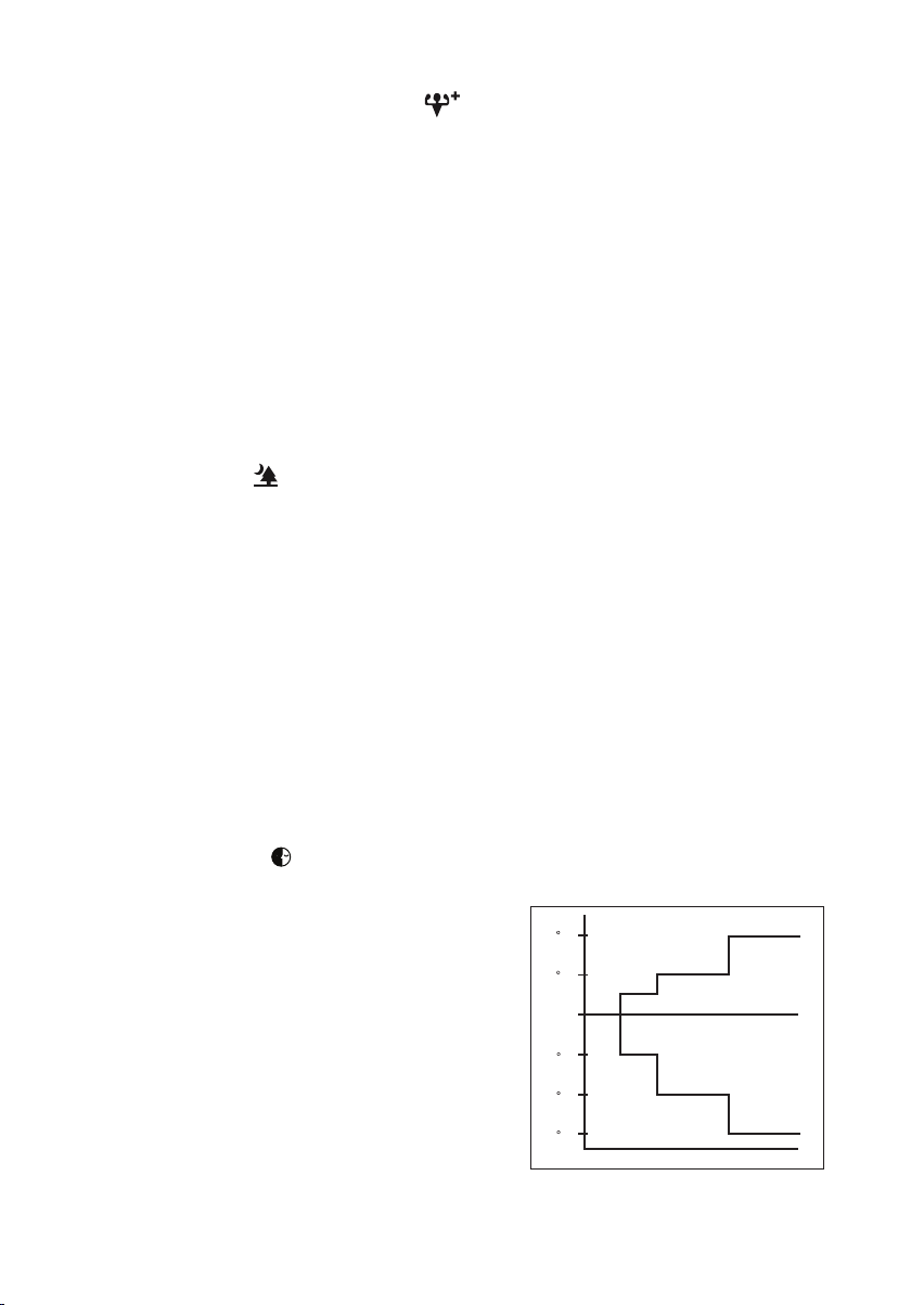
12. Sleep mode setting
• Press the
button will activate the sleep mode function.
• This is an energy saving option. When the unit is operating under cooling mode,
the set temperature is increased by 0.5°C after
the fi rst half an hour, another 0.5°C after the
second half an hour and 1°C after the following
1 hour.
+2 C
+1 C
• When the unit is operating under heating
mode, the set temperature is decreased by
1°C after the fi rst half an hour, another 1°C
- 1 C
after the second half an hour and 1°C after the
following 1 hour.
• This function is available under COOL,
HEAT and AUTO mode.
- 2 C
- 3 C
0 0.5 1 1.5 2
2
Page 11

13. Temperature setting
• To set the desired room temperature, press the
or button to increase or decrease
the set temperature.
• The temperature setting range is from 16°C to 30°C (Optional setting 20°C to
30°C).
• Press both buttons
and simultaneously to toggle from °C to °F setting.
14. ECO+ function
ENGLISH
• Press
for eco-friendly mode cooling or heating operation.
• Set temperature automatically adjust to eco-friendly level.
• Press again to deactivate the function.
• Available under HEAT and COOL modes only.
15. LED function
• Press
to turn on/off the light on ceiling cassette unit.
• Continuosly press for 5 seconds to turn on/off the LED display on wall mounted
unit.
• Available under HEAT, COOL, DRY, FAN and AUTO modes only.
16. Sense function
• Press intelligent eco cooling, heating or dry mode operation.
• Temperature display on wireless handset will automatically display 24°C as the
eco-friendly level.
• Press again to deactivate the function.
• Available under HEAT, COOL and DRY mode.
3
Page 12

FAULT DIAGNOSIS (For Inverter only)
FAULT DIAGNOSIS BY REMOTE CONTROLLER
The temperature display sections indicate corresponding codes.
When the ON TIMER CANCEL button or OFF TIMER CANCEL button is held down for 5
1.
seconds, a “ ” indication flashes on the temperature display section.
ON/OFF
TEMP
SWING
MODEFAN
SLEEPQUIET
POWERFUL
ECO+
SENSE
LED
TIMER
OFF
ON TIMER CANCEL OFF TIMER CANCEL
Press the ON TIMER CANCEL button or OFF TIMER CANCEL button repeatedly until a
2.
continuous beep is produced.
The code indication changes as shown below, and notifies with a long beep.
•
ERROR CODE MEANING
00 NORMAL
A1 INDOOR PCB ERROR
A3 DRAIN PUMP ABNORMAL
A5 ANTIFREEZE (COOLING)/HEAT EXCHANGER OVERHEAT (HEATING)
A6 INDOOR FAN MOTOR ABNORMAL
AH ELECTRICAL AIR CLEANER ABNORMAL
C4 INDOOR HEAT EXCHANGER (1) THERMISTOR SHORT/OPEN
C5 INDOOR HEAT EXCHANGER (2) THERMISTOR SHORT/OPEN
C7 LOUVER LIMIT SWITCH ERROR
C9 INDOOR ROOM THERMISTOR SHORT/OPEN
E1 OUTDOOR PCB ERROR
E3 HIGH PRESSURE PROTECTION
E4 LOW PRESSURE PROTECTION
E5 COMPRESSOR MOTOR LOCK/COMPRESSOR OVERLOADED
E6 COMPRESSOR START-UP ERROR
E7 OUTDOOR DC FAN MOTOR LOCK
E8 AC INPUT OVER CURRENT
E9 EXV ERROR
EA 4 WAY VALVE ERROR
F3 DISCHARGE PIPE OVERHEAT
F6 HEAT EXCHANGER OVERHEAT
HO COMPRESSOR SENSOR SYSTEM ERROR
H3 HIGH PRESSURE SWITCH ERROR
H6 COMPRESSOR FEEDBACK DETECTION ERROR
H7 FAN MOTOR OVERLOADED/OVERCURRENT/SENSOR ABNORMAL
H8 AC CURRENT SENSOR ERROR
ON
CANCEL CLOCK
CANCEL
4
Page 13

ERROR CODE MEANING
H9 OUTDOOR AIR THERMISTOR SHORT/OPEN
J1 PRESSURE SENSOR ERROR
J3 COMPRESSOR DISCHARGE PIPE THERMISTOR SHORT/OPEN/MISPLACED
J5 SUCTION PIPE THERMISTOR SHORT/OPEN
J6 OUTDOOR HEAT EXCHANGER THERMISTOR SHORT/OPEN
J7 SUBCOOLING HEAT EXCHANGER THERMISTOR SHORT/OPEN
J8 LIQUID PIPE THERMISTOR SHORT/OPEN
J9 GAS PIPE THERMISTOR SHORT/OPEN
L1 INVERTER OUTDOOR PCB ERROR
L3 OUTDOOR CONTROL BOX OVERHEAT
L4 HEAT SINK OVERHEAT
L5 IPM ERROR/IGBT ERROR
L8 INVERTER COMPRESSOR OVERCURRENT
L9 COMPRESSOR OVERCURRENT PREVENTION
LC COMMUNICATION ERROR (OUTDOOR CONTROL PCB AND INVERTER PCB)
P1 OPEN PHASE OR VOLTAGE UNBALANCE
P4 HEAT SINK THERMISTOR SHORT/OPEN
PJ CAPACITY SETTING ERROR
U0 INSUFFICIENT GAS
U2 DC VOLTAGE OUT OF RANGE
U4 COMMUNICATION ERROR
U7 COMMUNICATION ERROR (OUTDOOR CONTROL PCB AND IPM PCB)
UA INSTALLATION ERROR
UF
UH ANTIFREEZE (OTHER ROOMS)
PIPING & WIRING INSTALLATION MISMATCH/WRONG WIRING/INSUFFICIENT GAS
NOTE
1. A short beep and two consecutive beeps indicate non-corresponding codes.
2. To cancel the code display, hold the ON TIMER CANCEL button or OFF TIMER CANCEL button
down for 5 seconds. The code display also cancel itself if the button is not pressed for 1 minute.
ENGLISH
5
Page 14

MODE D’EMPLOI
1. Source de transmission
La source d’où le signal sera transmis.
•
2. Indication de transmission de signal
Clignotement pour confirmer que le dernier réglage ait été transmis à l’unité.
•
3. Bouton « ON/OFF » (MARCHE’/ARRÊT)
Appuyez une fois pour mettre le climatiseur en marche.
•
Appuyez de nouveau pour éteindre le climatisateur.
•
4. Sélection de la vitesse du ventilateur
Appuyez de façon continue sur le bouton
•
ventilateur comme suit :
Lent Moyen Rapide Auto
Cessez d’appuyer lorsque la vitesse désirée apparaît sur l’écran d’affichage.
•
5. Mode opérationnel
Appuyez sur le bouton MODE pour sélectionner le type de mode opérationnel.
•
Pour l’unité de refroidissement, les modes disponibles comprennent : COOL (
•
DRY ( ) (SEC) et FAN ( ) (VENTILATION).
Pour l’unité de thermopompe, les modes disponibles comprennent : AUTO ( ) (AUTO),
•
COOL ( ) (FROID), DRY ( ) (SEC), FAN ( ) (VENTILATION) et HEAT ( )
(CHAUD).
Le mode AUTO ( ) (AUTO) n’est pas disponible pour le système à eau glacée à l’exception
•
du système à 4 conduites.
6. Oscillation automatique de la ventilation
Appuyez sur le bouton SWING
•
ventilation.
Pour orienter la ventilation dans une direction précise, appuyez sur le bouton SWING , attendez
•
ensuite que le volet de ventilation souffle dans la direction désirée puis appuyez de nouveau sur le
bouton.
Méthode de sélection du mode Swing (dépendant du modèle)
Appuyez sur le bouton SWING ( ) pendant 4 secondes pour entrer dans le mode de réglage du
•
champ. En mode de réglage local, seul le mode d’oscillation SWING MODE ( ) est affiché.
Appuyez sur le bouton de température et pour sélectionner la rotation du SWING MODE
•
( ) depuis le Mode Swing 1 au Mode Swing 3.
Les 3 différents modes d’oscillation (SWING MODE) suivants sont disponibles :
•
pour transformer successivement la vitesse du
) (FROID),
pour activer la fonction d’oscillation automatique de la
Mode d’oscillation 1 Mode d’oscillation 2 Mode d’oscillation 3
Le mode d’oscillation (SWING MODE) ne sera pas activé, sauf si la fonction d’oscillation
(SWING) est activée.
L’oscillation est indiquée par le logo :
Si aucun mode ne change dans les 4 secondes, l’appareil fonctionnera selon le SWING MODE
•
( ) sélectionné.
6
Page 15

7. Fonction Powerful & Powerful+
Appuyez sur le bouton
•
Le ventilateur tourne à sa vitesse maximale.
•
Pressez de nouveau pour refroidissement ou réchauffement intelligent.
•
Le ventilateur tourne à sa vitesse maximale et le volet sera ajusté en fonction du jugement du
•
pour refroidissement ou réchauffement rapide.
capteur fonction.
Pressez de nouveau pour désactiver la fonction.
•
Disponible seulement sur le mode HEAT (CHAUD) et COOL (FROID).
•
Toute modification de la vitesse du ventilateur entraîne l’arrêt de cette fonction.
•
8. Programmer la minuterie d’arrêt
Appuyez sur le bouton OFF TIMER pour activer la minuterie d’arrêt.
•
Programmez l’heure désirée en appuyant continuellement sur le bouton OFF TIMER.
•
Appuyez sur le bouton CANCEL pour annuler le programmation d’arrêt.
•
9. Fonction silence (dépendant du modèle)
Appuyez sur
•
•
Le ventilateur tourne à sa vitesse minimale.
•
Pressez de nouveau pour désactiver la fonction.
•
Disponible seulement sur le mode HEAT (CHAUD) et COOL (FROID).
•
Toute modification de la vitesse du ventilateur entraîne l’arrêt de cette fonction.
pour un fonctionnement silencieux.
10. Mettre l’horloge à l’heure
•
Maintenez le bouton CLOCK enfoncé pour mettre l’horloge à l’heure.
11. Programmer la minuterie de mise en marche
Appuyez sur le bouton ON TIMER pour activer la minuterie de mise en marche.
•
Programmez l’heure désirée en appuyant continuellement sur le bouton ON TIMER. Si la
•
minuterie est programmée à 7h30, le climatiseur se mettra en marche à 7h30 pile.
Appuyez sur le bouton CANCEL pour annuler le programmation de la minuterie.
•
12. Réglage du mode de nuit
Appuyez sur le bouton
•
Ceci est une option anti-gaspillage d’énergie. Lorsque l’unité fonctionne en mode de
•
pour activer la fonction de mode de nuit.
refroidissement, la température réglée augmente de
0,5°C au bout de la première demi-heure, d’encore
0,5°C au bout de la deuxième demi-heure et d’1°C au
bout de l’heure suivante.
Lorsque l’unité fonctionne en mode de chauffage,
•
la température réglée diminue d’1°C au bout de la
première demi-heure, d’encore 1°C au bout de la
deuxième demiheure et d’1°C au bout de l’heure
suivante.
Cette fonction est disponible en mode COOL
•
(FROID), HEAT (CHAUD) et AUTO (AUTO).
+2 C
+1 C
- 1 C
- 2 C
- 3 C
0 0,5 1 1,5 2
FRANÇAIS
Traduction des instructions d’origine
7
Page 16

13. Réglage de la température
Pour régler la température au niveau que vous souhaitez, appuyez sur le bouton
•
ou pour
l’augmenter ou la baisser.
La température se régle de 16°C à 30°C (Possibilité de régler de 20°C à 30°C).
•
Appuyez sur les boutons et simultanément pour passer des °C aux °F et inversement.
•
14. Fonction ECO+
•
Pressez
•
La température défi nie est automatiquement ajustée au niveau respectueux de l’environnement.
•
Pressez de nouveau pour désactiver la fonction.
•
Disponible seulement sur le mode HEAT (CHAUD) et COOL (FROID).
pour refroidissement ou réchauffement en mode respectueux de l’environnement.
15. Fonction LED
•
Pressez
•
Pressez de manière continue pendant 5 secondes pour allumer/éteindre le voyant LED sur
pour allumer/éteindre la lumière sur l’unité cassette de plafond.
l’unité murale.
•
Disponible seulement sur le mode HEAT (CHAUD), COOL (FROID), DRY (SEC), FAN
(VENTILATION) et AUTO.
16. Fonction Sense
•
Pressez
•
La température affi chée sur le combiné sans fi l sera automatiquement de 24 °C en tant que
pour un refroidissement, réchauffement ou déshumidifi cation éco intelligent.
niveau respectueux de l’environnement.
•
Pressez de nouveau pour désactiver la fonction.
•
Disponible seulement sur le mode HEAT (CHAUD), COOL (FROID) et DRY (SEC).
8
Page 17

FAUX DIAGNOSTICS (pour modèle à inverseur seulement)
FAUX DIAGNOSTICS PAR LA TELECOMMANDE
La partie d’affichage de la température indique les codes correspondants.
1.
Lorsque le bouton Annuler de la mise en marche par minuterie ON TIMER CANCEL (ANNULER LA
MISE À L’ARRÊT PAR MINUTERIE) ou le bouton de la mise à l’arrêt par minuterie OFF TIMER
CANCEL (ANNULER LA MISE EN MARCHE PAR MINUTERIE) est enfoncé pendant 5 secondes,
un signe «
(ANNULER LA MISE EN MARCHE
2.
Appuyez sur le bouton ON TIMER CANCEL (ANNULER LA MISE EN MARCHE PAR MINUTERIE) ou
OFF TIMER CANCEL (ANNULER LA MISE À L’ARRÊT PAR MINUTERIE) répétitivement jusqu’à ce
qu’un bip continu se produise.
• L’indication du code change comme montré ci dessous, et notifie avec un long bip.
CODE DE
L’ERREUR
A1 ERREUR PCB DANS LA SECTION INTÉRIEURE
A3 ANOMALIE DE LA POMPE DE VIDANGE
A5 ANTIGEL (REFROIDISSEMENT) / ÉCHANGEUR DE CHALEUR DE SURCHAUFFE(CHAUFFAGE)
A6 ANOMALIE SUR LE VENTILATEUR D’INTÉRIEUR
AH ANOMALIE DU FILTRE À AIR ÉLECTRIQUE
EA ERREUR DE VANNE À 4 VOIES
HO ERREUR DU SYSTÈME DE CAPTEUR DU COMPRESSEUR
H3 ERREUR DE L’INTERRUPTEUR HAUTE PRESSION
H6 ERREUR DE DÉTECTION DE L’ALIMENTATION DU COMPRESSEUR
H7 SURCHARGE/SURINTENSITÉ DU MOTEUR DU VENTILATEUR/ANOMALIE DU CAPTEUR
H8 ERREUR DU CAPTEUR DE COURANT CA
» clignote sur la partie d’affichage de la température.
ON/OFF
TEMP
SWING
MODEFAN
POWERFUL
SLEEPQUIET
ECO+
SENSE
LED
ON TIMER CANCEL
PAR MINUTERIE)
TIMER
ON
CANCEL CLOCK
CANCEL
OFF
OFF TIMER CANCEL
(ANNULER LA MISE À L’ARRÊT
PAR MINUTERIE)
SIGNIFICATION
00 NORMAL
C4 THERMISTOR DE L’ÉCHANGEUR THERMIQUE INTÉRIEUR (1) EN COURT-CIRCUIT/OUVERT
C5 THERMISTOR DE L’ÉCHANGEUR THERMIQUE INTÉRIEUR (2) EN COURT-CIRCUIT/OUVERT
C7 ERREUR DE L’INTERRUPTEUR DE LIMITE D’AILETTE
C9 COURT-CIRCUIT/OUVERTURE DANS LE THERMISTOR DE PIÈCE INTÉRIEURE
E1 ERREUR DE CARTE EXTÉRIEURE
E3 PROTECTION HAUTE PRESSION
E4 PROTECTION BASSE PRESSION
E5 VERROU DU MOTEUR DU COMPRESSEUR /COMPRESSEUR SURCHARGÉ
E6 ERREUR DE DÉMARRAGE DU COMPRESSEUR
E7 VERROU DU MOTEUR DE VENTILATEUR CC EXTÉRIEURE
E8 SURINTENSITÉ D’ENTRÉE CA
E9 ERREUR EXV
F3 TUYAUTERIE DE VIDANGE DE SURCHAUFFE
F6 ÉCHANGEUR DE CHALEUR DE SURCHAUFFE
9
FRANÇAIS
Page 18

CODE DE
L’ERREUR
H9 THERMISTANCE À AIR EXTÉRIEUR EN COURT-CIRCUIT/OUVERT
J1 ERREUR DU CAPTEUR DE PRESSION
J3 THERMISTANCE DE LA TUYAUTERIE DE VIDANGE DU COMPRESSEUR EN COURT-CIRCUIT/
OUVERTE/ MAL POSITIONNÉE
J5 COURT-CIRCUIT/OUVERTURE DANS LE THERMISTOR DU TUYAU D’ASPIRATION
J6 THERMISTANCE D’ÉCHANGEUR DE CHALEUR EXTÉRIEUR EN COURT-CIRCUIT/OUVERT
J7 COURT-CIRCUIT/OUVERTURE DANS LE THERMISTOR DE L’ÉCHANGEUR THERMIQUE DE
SOUS- REFROIDISSEMENT
J8 THERMISTANCE DE LA TUYAUTERIE DU LIQUIDE EN COURT-CIRCUIT/OUVERTE
J9 THERMISTANCE DE LA TUYAUTERIE DE GAZ EN COURT-CIRCUIT/OUVERTE
L1 ERREUR PCB EXTÉRIEURE DE L’INVERSEUR
L3 BOÎTIER DE COMMANDE EXTÉRIEUR DE SURCHAUFFE
L4 DISSIPATEUR THERMIQUE DE SURCHAUFFE
L5 ERREUR IPM /ERREUR IGBT
L8 SURINTENSITÉ DU COMPRESSEUR DE L’INVERSEUR
L9 PRÉVENTION DE SURINTENSITÉ DU COMPRESSEUR
ERREUR DE COMMUNICATION (PCB DE LA COMMANDE EXTÉRIEURE ET PCB DE L’INVERSEUR)
LC
P1 PHASE OUVERTE OU DÉSÉQUILIBRE DE TENSION
P4 THERMISTANCE DE DISSIPATEUR DE CHALEUR EN COURT-CIRCUIT/OUVERT
PJ ERREUR DE RÉGLAGE DE LA CAPACITÉ
U0 INSUFFISANCE DE GAZ
U2 TENSION CC HORS PLAGE
U4 ERREUR DE COMMUNICATION
U7 ERREUR DE COMMUNICATION (CARTE DE COMMANDE ET CARTE IPM)
UA ERREUR D’INSTALLATION
UF MAUVAISE CORRESPONDANCE DANS L’INSTALLATION DU CÂBLAGE ET DE LA TUYAUTERIE/
MAUVAIS CÂBLAGE/INSUFFISANCE EN GAZ
UH ANTIGEL (AUTRES PIÈCES)
SIGNIFICATION
REMARQUE
1. Un bip bref et deux bip consécutifs indique qu’il n’y a pas de codes correspondants.
2. Pour annuler l’affichage du code, appuyez pendant 5 secondes sur le bouton ON TI MER CANCEL
(ANNULER LA MISE EN MARCHE PAR MINUTERIE) ou OFF TIMER CANCEL (ANNULER
LA MISE À L’ARRÊT PAR MINUTERIE). Le code affiché s’annule lui même si le bouton n’est
pas appuyé pendant 1 minute.
10
Page 19

GEBRAUCHSANWEISUNG
1. Sendungsquelle
Die Ausgangsquelle des Signals.
•
2. Signalübertragungsanzeige
Blinkt auf, um anzuzeigen, dass das letzte Signal an das Gerät übertragen wurde.
•
3. “ON/OFF” („AN/AUS“) schalter
Einmal betätigen - das Gerät schaltet sich ein.
•
Nochmals betätigen - das Gerät schaltet sich aus.
•
4. Wahl der drehzahl-Stufe des kühlgebläses
Wird der
•
Kühlgebläses in dieser Reihenfolge:
Den Knopf nicht weiter betätigen, wenn die gewünschte Drehzahlstufe des Kühlgebläses angezeigt
•
wird.
5. Betrieb
Zur Wahl der verschiedenen Arten des Betriebs wird der MODE Knopf betätigt.
•
Für die Kühlung kann man COOL (
•
(GEBLÄSE) wählen.
Für den Betrieb der Wärmepumpe hat man die Wahl zwischen: AUTO ( ) (AUTO), COOL ( )
•
(KÜHL), DRY ( ) (TROCKEN), FAN ( ) (GEBLÄSE) und HEAT ( ) (WARM).
Der AUTO ( ) (AUTO) Modus steht für das Kaltwassersystem nicht zur Verfügung eine
•
Ausnahme bildet das 4-Rohr-System.
6. Automatische Luftschwingung
Durch Betätigen des SWING
•
Damit die Luft in eine bestimmte Richtung bläst, wird der SWING Knopf betätigt, danach
•
warten, bis sich die Lüftungsschlitze in die gewünschte Richtung bewegen und dann den Knopf
nochmals betätigen.
Auswahlverfahren für Swing-Modus (von Model abhängig)
Drücken Sie die Taste SWING ( ) für 4 Sekunden lang, um in das Feld des Einstellmodus zu
•
gelangen. Im Feldeinstellungsmodus erscheint nur die Meldung SWING MODE ( ).
Drücken Sie die Temperaturtaste und um die Drehzahl von SWING MODE ( ) von
•
Swing-Modus 1 bis auf Swing-Modus 3 auszuwählen.
Folgende drei automatische Luftschwenkmodi (SWING MODE) stehen zur Verfügung:
•
Knopf kontinuierlich betätigt, dann ändert sich jeweils die Drehzahlstufe des
Niedrig Mittel Hoch Automatisch
) (KÜHL), DRY ( ) (TROCKEN) und FAN ( )
Knopfs wird die automatische Luftschwingungsfunktion aktiviert.
DEUTSCH
Übersetzung der Original-Anleitungen
Luftschwenkmodus 1 Luftschwenkmodus 2 Luftschwenkmodus 3
SWING MODE wird erst aktiviert, wenn SWING eingeschaltet ist.
Der Schwenkmodus wird durch dieses Logo angezeigt:
Falls sich keiner Modus innerhalb 4 Sekunden ändert, funktioniert das Gerät gemäß den
•
ausgewählten SWING MODE ( ).
11
Page 20
7. Stark & Stark+ - Funktion
Zum schnellen Kühlen oder Erwärmen die Taste betätigen.
•
Gebläsedrehzahl wird auf Höchstgeachwindigkeit gebracht.
•
Zum intelligenten Kühlen oder Erwärmen die Taste erneut betätigen
•
Bei Einstellung der Lüftergeschwindigkeit auf maximale Geschwindigkeit wird das Lüftungsgitter
•
nach Ermessen des Sense-Funktion angepasst.
Drücken Sie erneut, um diese Funktion zu deaktivieren.
•
Erhältlich nur für HEAT (WÄRME) und COOL (KÜHL) betrieb.
•
Die Funktion wird durch eine Veränderung der Gebläsedrehzahl ausgeschaltet.
•
8. AUS - Zeitschalter-einstellung
Die Funktion des AUS - Zeitschalters wird durch Betätigen des OFF TIMER -Knopfes aktiviert.
•
Den OFF TIMER -Knopf solange betätigen, bis die gewünschte Ausschaltungszeit angezeigt und
•
somit eingestellt ist.
Zum Löschen der Einstellung des AUS - Zeitschalters wird der CANCEL Knopf betätigt.
•
9. Ruhefunktion (von Model abhängig)
Für leisen Betrieb
•
Gebläsedrehzahl wird auf Mindestgeschwindigkeit gebracht.
•
Drücken Sie erneut, um diese Funktion zu deaktivieren.
•
Erhältlich nur für HEAT (WÄRME) und COOL (KÜHL) betrieb.
•
Die Funktion wird durch eine Veränderung der Gebläsedrehzahl ausgeschaltet.
•
drücken.
10. Einstellen der Uhrzeit
Drücken Sie zur Einstellung der Uhrzeit die CLOCK-Taste und halten Sie sie gedrückt.
•
11. EIN - Zeitschalter-einstellung
Die Funktion des EIN - Zeitschalters wird durch Betätigen des ON TIMER -Knopfes aktiviert.
•
Den ON TIMER -Knopf solange betätigen, bis die gewünschte Zeit angezeigt und somit eingestellt
•
wird. Ist der Zeitschalter auf 7.30 Uhr eingestellt, so schaltet sich die Klimaanlage genau um diese
Zeit ein.
Zum Löschen der Einstellung des EIN - Zeitschalters wird der CANCEL Knopf betätigt.
•
12. Einstellen des Nachtbetriebs
Durch Betätigen des Knopfs wird der Nachtbetrieb aktiviert.
•
Dabei kann man Energie sparen. Befindet sich das Gerät im Kühlmodus, steigt die eingestellte
•
Temperatur nach der ersten halben Stunde um 0,5°C.
Nach der zweiten halben Stunde steigt die Temperatur
um weitere 0,5°C und um 1°C nach der folgenden
Stunde.
Befindet sich das Gerät im Heizmodus, sinkt die
•
eingestellte Temperatur nach der ersten halben Stunde
um 1°C. Nach der zweiten halben Stunde sinkt die
Temperatur um weitere 1°C und um 1°C nach der
folgenden Stunde.
Diese Funktion gibt es bei COOL (KÜHL), HEAT
•
(WARM) und AUTO (AUTO) Betrieb.
+2 C
+1 C
- 1 C
- 2 C
- 3 C
0 0,5 1 1,5 2
12
Page 21

13. Temperatureinstellung
Um die gewünschte Temperatur einzustellen, den oder den Knopf betätigen, so wird die
•
eingestellte Temperatur höher oder niedriger gestellt.
Der Temperatur-Einstellbereich liegt zwischen 16°C zu 30°C (Die optimale Einstellung liegt
•
zwischen 20°C zu 30°C).
Drücken Sie gleichzeitig die Tasten und , um von °C auf °F umzustellen.
•
14. ECO+ - Funktion
Für den umweltfreundlichen Modus für Kühl- oder Erwärmungstätigkeiten die Taste
•
Eingestellte Temperatur wird automatisch an die umweltfreundliche Stufe angepasst.
•
Drücken Sie erneut, um diese Funktion zu deaktivieren.
•
Erhältlich nur für HEAT (WÄRME) und COOL (KÜHL) betrieb.
•
betätigen.
15. LED - Funktion
Um das Licht an der Deckenkassetteneinheit ein-/auszuschalten, die Taste
•
Um die LED-Anzeige am Wandgerät ein-/auszuschalten, die Taste 5 Sekunden gedrückt
•
betätigen.
halten.
Erhältlich nur für HEAT (WÄRME), COOL (KÜHL), DRY(TROCKEN), FAN (GEBLÄSE)
•
und AUTO betrieb.
16. Messfunktion
Für den intelligenten umweltfreundlichen Kühl-, Erwärmungs- oder Entfeuchtungsmodus die Taste
•
betätigen.
Die Temperaturanzeige auf dem drahtlosen Handgerät zeigt für die umweltfreundliche Stufe
•
automatisch 24°C an.
Drücken Sie erneut, um diese Funktion zu deaktivieren.
•
Erhältlich nur für HEAT (WÄRME), COOL (KÜHL) und DRY(TROCKEN) betrieb.
•
DEUTSCH
13
Page 22

FEHLERBEHANDLUNG (Nur für Inverter)
FEHLERBEHANDLUNG ÜBER DIE FERNBEDIENUNG
Die Temperaturabschnitte auf dem Display zeigen entsprechende Codes an.
1. Wenn die ON TIMER CANCEL Taste (TIMER EIN ABBRECHEN) oder die OFF TIMER
CANCEL Taste (TIMER AUS ABBRECHEN) 5 Sekunden lang gedrückt wird, wird „ “ blinkend
auf dem Temperaturabschnitt des Displays angezeigt.
ON/OFF
TEMP
SWING
MODEFAN
SLEEPQUIET
POWERFUL
ECO+
SENSE
LED
TIMER
OFF
ON TIMER CANCEL
(TIMER EIN ABBRECHEN)
2. Drücken Sie die ON TIMER CANCEL Taste (TIMER EIN ABBRECHEN) oder die OFF TIMER
CANCEL Taste (TIMER AUS ABBECHEN) so lange, bis ein Piepen ertönt.
• Die Codeanzeige ändert sich wie unten, und es ertönt ein langes Piepen.
FEHLERMELDUNG BEDEUTUNG
00 NORMAL
A1 LEITERPLATTENFEHLER DER INNENEINHEIT
A3 ABLAUFPUMPE ANOMAL
A5 FROSTSCHUTZ (KÜHLUNG)/WÄRMEAUSTAUSCHER ÜBERHITZT (HEIZUNG)
A6 INNENLÜFTER, MOTOR ANOMAL
AH FEHLER AN ELEKTRO-LUFTREINIGER
C4 INNENRAUMWÄRMETAUSCHER (1) THERMISTOR, KURZSCHLUSS/UNTERBRECHUNG
C5 INNENRAUMWÄRMETAUSCHER (2) THERMISTOR, KURZSCHLUSS/UNTERBRECHUNG
C7 FEHLER AN ENDSCHALTER DER LUFTKLAPPE
C9 INNENRAUMTHERMISTOR, KURZSCHLUSS/UNTERBRECHUNG
E1 AUSSEN-PBC-FEHLER
E3 HOCHDRUCKSCHUTZ
E4 NIEDERDRUCKSCHUTZ
E5 KOMPRESSORMOTOR VERRIEGELT/KOMPRESSOR ÜBERLASTET
E6 KOMPRESSOR-ANLAUFFEHLER
E7 DC-AUSSENVENTILATORMOTOR VERRIEGELT
E8 AC-EINGANGSSTROM ZU HOCH
E9 EXV FEHLER
EA VIERWEGVENTILFEHLER
F3 AUSLASSROHR ÜBERHITZT
F6 WÄRMEAUSTAUSCHER ÜBERHITZT
HO KOMPRESSORENSENSOR-SYSTEMFEHLER
H3 FEHLER AN HOCHDRUCKSCHALTER
H6 KOMPRESSOR-FEEDBACK-ERFASSUNGSFEHLER
H7 VENTILATORMOTOR ÜBERLASTET/ÜBERSPANNUNG/SENSORFEHLER
H8 AC-STROM-SENSORFEHLER
ON
CANCEL CLOCK
14
CANCEL
OFF TIMER CANCEL
(TIMER AUS ABBRECHEN)
Page 23

FEHLERMELDUNG BEDEUTUNG
H9 AUSSENLUFT-THERMISTOR KURZ/OFFEN
J1 FEHLER AN DRUCKFÜHLER
J3 KOMPRESSORABLUFTROHR-THERMISTOR KURZ/OFFEN/VERLEGT
J5 KURZSCHLUSS/UNTERBRECHUNG AN ANSAUGTHERMISTOR
J6 AUSSENTÜRWÄRMEAUSTAUSCHER KURZ/OFFEN
J7
J8 FLÜSSIGKEITSLEITUNGSROHR-THERMISTOR KURZ/OFFEN
J9 GASLEITUNGSROHR-THERMISTOR KURZ/OFFEN
L1 FEHLER AN LEITERPLATTE DES INVERTERS
L3 STEUERKASTEN AUSSEN ÜBERHITZT
L4 KÜHLKÖRPER ÜBERHEIZT
L5 IPM FEHLER/IGBT FEHLER
L8 ÜBERSPANNUNG AN INVERTERKOMPRESSOR
L9 ÜBERSPANNUNGSSCHUTZ AM KOMPRESSOR
LC ÜBERTRAGUNGSFEHLER (LEITERPLATTE AN AUSSENSTEUERUNG UND INVERTER)
P1 OFFENE PHASE ODER SPANNUNGSUNTERSCHIEDE
P4 KÜHLKÖRPER-THERMISTOR KURZ/OFFEN
PJ FEHLER BEI LEISTUNGSEINSTELLUNG
U0 GAS UNGENÜGEND
U2 DC-SPANNUNG NICHT IM NORMALBEREICH
U4 KOMMUNIKATION, FEHLER
U7 KOMMUNIKATIONSFEHLER (STEUER-PCB UND IPM-PCB AUSSEN)
UA INSTALLATIONSFEHLER
UF
UH FROSTSCHUTZ (ANDERE RÄUME)
KURZSCHLUSS/UNTERBRECHUNG AN UNTERKÜHLUNGSTHERMISTOR DES WÄRMETAUSCHERS
FEHLERHAFTE VERROHRUNG & VERDRAHTUNG/FALSCH VERKABELT/ZU WENIG GAS
ANMERKUNG
1. Ein kurzer und zwei aufeinander folgende Pieptöne deuten auf nicht übereinstimmende Codes hin.
2. Um das Code-Display zu verlassen, halten Sie die ON TIMER CANCEL Taste (TIMER EIN ABBRECHEN)
oder die OFF TIMER CANCEL Taste (TIMER AUS ABBRECHEN) 5 Sekunden lang gedrückt. Das CodeDisplay erlischt auch von selbst, wenn 1 Minute lang keine Tasten gedrückt werden.
DEUTSCH
15
Page 24

GUIDA ALL’USO
1. Fonte di trasmissione
•
La fonte dalle quale viene trasmesso il segnale.
2. Indicatore di trasmissione
•
L’indicatore lampeggia per confermare l’invio dell’ultimo valore al condizionatore.
3. Tasto “ON/OFF”
•
Premere una volta per accendere il condizionatore.
•
Premere ancora per spegnerlo.
4. Selezione velocità ventola
•
Tenendo premuto il tasto
Bassa Media Alta Automatica
Deprimete il tasto una volta che la velocità desiderata appare sul display.
•
5. Funzioni
Premere il tasto MODE per selezionare la funzione desiderata.
•
Per condizionatori con la sola funzione rinfrescante “cooling”, le funzioni disponibili sono:
•
COOL (
Per unità con funzione di riscaldamento, le funzioni disponibili sono: AUTO ( )
•
) (FRESCO), DRY ( ) (SECCO) e FAN ( ) (VENTOLA).
(AUTOMATICO), COOL ( ) (FRESCO), DRY ( ) (SECCO), FAN ( ) (VENTOLA)
e HEAT ( ) (CALDO).
La modalità AUTO ( ) (AUTOMATICO) non è disponibile per sistemi raffreddati ad acqua,
•
tranne che per il sistema a 4 condotti.
6. Deviatore di flusso orientabile automatico
Premere il tasto SWING
•
Per distribuire il flusso d’aria in una direzione specifica, premere il tasto SWING ed aspettare
•
fino a che le alette dei ventilazione si posizionano nella direzione desi-erata quindi premere
nuovamente il tasto.
Metodo di scelta della modalità di oscillazione (a seconda del modello)
Premere il pulsante SWING ( ) per 4 secondi per entrare nella modalità impostazione
•
campo. In modalità impostazione locale, si visualizza solo la SWING MODE ( )
(MODALITÀ SWING).
Premere il pulsante temperatura e per selezionare il passaggo della SWING MODE ( )
•
(MODALITÀ SWING) da modalità oscillazione 1 a modalità oscillazione 3.
Ci sono 3 diverse SWING MODE (MODALITÀ SWING) che sono:
•
la velocità della ventola cambiera’ nel seguente ordine:
per attivare l’oscillazione dell’aria.
Modalità swing 1 Modalità swing 2 Modalità swing 3
La SWING MODE (MODALITÀ SWING) non si attiva se non è attivato SWING.
Swing è indicato dal logo:
Se non c’è nessun cambio di modalità entro 4 secondi, l’unità funzione secondo la SWING
•
MODE ( ) (MODALITÀ SWING) selezionata.
16
Page 25

7. Funzione Powerful e Powerful+
Premere per un reffreddamento o riscaldamento veloce.
•
Velocità ventola impostata su massimo.
•
Premere di nuovo per un raffreddamento o riscaldamento intelligente.
•
La velocità ventola viene impostata sul massimo e la feritoia viene regolata in base alla valutazione
•
del sensore funzione.
Premerlo nuovamente per disattivare la funzione.
•
Disponibile solo nelle funzioni HEAT (CALDO) e COOL (FRESCO)
•
Qualsiasi modifica alla velocità della ventola disattiva questa funzione.
•
8. Impostazione del temporizzatore per lo spegnimento automatico
Premere il tasto OFF TIMER per annullare il settaggio del temporizzatore.
•
Impostare l’orario prescelto tenendo premuto il tasto OFF TIMER .
•
Premere il tasto CANCEL per annullare l’orario impostato.
•
9. Funzione silenziosa (a seconda del modello)
Premere
•
Velocità ventola impostata su minimo.
•
Premerlo nuovamente per disattivare la funzione.
•
Disponibile solo nelle funzioni HEAT (CALDO) e COOL (FRESCO).
•
Qualsiasi modifica alla velocità della ventola disattiva questa funzione.
•
per selezionare il funzionamento silenzioso.
10. Settaggio dell’orario
Premi e mantieni premuto il tasto
•
CLOCK
per regolare l’ora dell’orologio.
11. Impostazione del temporizzatore per l’accensione automatica
Premere il tasto ON TIMER per attivare il temporizzatore.
•
Impostare l’ora prescelta tenendo premuto il tasto ON TIMER . Se il temporizzatore viene settato
•
per le 0730 del mattino, il condizionatore si accendera’ automaticamente a quest’ora.
Premere il tasto CANCEL per annullare l’orario impostato.
•
12. Funzione di “riposo”
Premere il tasto
•
per attivare la funzione di
“riposo”.
Questa èuna funzione per risparmio energetico. Quando
•
+2 C
+1 C
l’unità funziona in modalità di raffreddamento, la
temperatura impostata viene aumentata di 0,5°C dopo
la prima mezz’ora, di altri 0,5°C dopo la seconda
mezz’ora, e di 1°C dopo l’ora seguente.
Quando l’unità funziona in modalità di riscaldamento,
•
la temperatura impostata viene ridotta di 1°C dopo la
prima mezz’ora, di un altro grado dopo la seconda
- 1 C
- 2 C
- 3 C
0 0,5 1 1,5 2
mezz’ora, e di 1°C dopo l’ora seguente.
Questa funzione opera nelle funzioni COOL (FRESCO), HEAT (CALDO) ed AUTO
•
(AUTOMATICO).
ITALIANO
Traduzione delle istruzioni originali
17
Page 26

13. Valori di temperatura
Per selezionare la temperatura desiderata premere i tasti o rispettivameñte per aumentare
•
o diminuire la temperatura.
I valori di temperatura sono compresi tra i 16°C a 30°C (Valori opzionali da 20°C a 30°C).
•
Premere contemporaneamente i tasti e per passare dalle impostazioni °C a °F.
•
14. Funzione ECO+
• Premere
per un raffreddamento o riscaldamento in modalità ecologica
• Impostare automaticamente la regolazione della temperatura sul livello ecologico.
• Premerlo nuovamente per disattivare la funzione.
• Disponibile solo nelle funzioni HEAT (CALDO) e COOL (FRESCO).
15. Funzione LED
• Premere per accendere/spegnere la luce sulla cassetta a soffi tto.
• Tenere premuto per 5 secondi per accendere/spegnere il display LED sull'unità montata a
muro.
Disponibile solo nelle funzioni HEAT (CALDO), COOL (FRESCO), DRY (SECCO) e
•
AUTO (AUTOMATICO).
16. Funzione Sense
• Premere per un raffreddamento, riscaldamento o funzionamento in modalità deumidifi ca
ecologico intelligente.
• La visualizzazione della temperatura sul ricevitore senza fi li mostra automaticamente 24°C come
livello ecologico.
• Premerlo nuovamente per disattivare la funzione.
Disponibile solo nelle funzioni HEAT (CALDO), COOL (FRESCO) e DRY (SECCO).
•
18
Page 27

SEGNALAZIONE ERRORE (Solo per inverter)
SEGNALAZIONE ERRORE SUL TELECOMANDO
Le sezioni di visualizzazione della temperatura indicano i codici corrispondenti.
Quando il tasto ON TIMER CANCEL (ANNULLA TIMER ATTIVO) o OFF TIMER CANCEL
1.
(ANNULLA TIMER DISATTIVO) viene premuto per 5 secondi, un indicatore e “ ” inizierà a
lampeggiare sulla sezione di visualizzazione della temperatura.
ON/OFF
TEMP
SWING
MODEFAN
SLEEPQUIET
POWERFUL
ECO+
SENSE
LED
TIMER
OFF
ON TIMER CANCEL
(ANNULLA TIMER ATTIVO)
2.
Premere ripetutamente il tasto ON TIMER CANCEL (ANNULLA TIMER ATTIVO) o OFF TIMER
CANCEL (ANNULLA TIMER DISATTIVO) fino a che non viene prodotto un beep continuo.
L’indicazione di codice cambia come sotto riportato e viene notificato da un beep prolungato.
•
CODICE
ERRORE
00
A1
A3
A5
A6
AH
C4
C5
C7
C9
E1
E3
E4
E5
E6
E7
E8
E9
EA
F3
F6
HO
H3
H6
H7
H8
NORMALE
ERRORE SCHEDA ELETTRONICA UNITÀ INTERNA
ANOMALIA POMPA DI SCARICO
SCAMBIATORE ANTIGELO (RAFFREDDAMENTO)/CALORE (RISCALDAMENTO)
ANOMALIA MOTORE VENTILATORE UNITÀ INTERNA
ANOMALIA ELETTRICA FILTRO DELL’ARIA
TERMISTORE SCAMBIATORE DI CALORE (1) UNITÀ INTERNA IN CORTO/APERTO
TERMISTORE SCAMBIATORE DI CALORE (2) UNITÀ INTERNA IN CORTO/APERTO
ERRORE INTERRUTTORE DI FINE CORSA FERITOIA DÌ VENTILAZIONE
TERMISTORE UNITÀ INTERNA IN CORTO/APERTO
ERRORE DEL PCB ESTERNO
PROTEZIONE DA ALTA PRESSIONE
PROTEZIONE BASSA PRESSIONE
BLOCCO DEL MOTORE COMPRESSORE/COMPRESSORE SOVRACCARICO
ERRORE DI AVVIAMENTO DEL COMPRESSORE
BLOCCO MOTORE VENTOLA CC ESTERNO
SOVRACORRENTE ENTRATA CA
ERRORE EXV
ERRORE DELLA VALVOLA A 4 VIE
SURRISCALDAMENTO DEL TUBO DI SCARICO
SURRISCALDAMENTO DELLO SCAMBIATORE DI CALORE
ERRORE DEL SISTEMA DEL SENSORE DEL COMPRESSORE
ERRORE INTERRUTTORE ALTA PRESSIONE
ERRORE DI RILEVAMENTO DEL FEEDBACK DEL COMPRESSORE
MOTORE VENTOLA SOVRACCARICATO/SOVRACORRENTE/ANOMALIA SENSORE
ERRORE DEL SENSORE DI CORRENTE CA
ON
CANCEL CLOCK
CANCEL
19
OFF TIMER CANCEL
(ANNULLA TIMER DISATTIVO)
SIGNIFICATO
ITALIANO
Page 28

CODICE
ERRORE
H9
J1
J3
J5
J6
J7
J8
J9
L1
L3
L4
L5
L8
L9
LC
P1
P4
PJ
U0
U2
U4
U7
UA
UF
UH ANTICONGELAMENTO (ALTRI AMBIENTI)
TERMISTORE ARIA ESTERNA IN CORTO/APERTO
ERRORE SENSORE DI PRESSIONE
TERMISTORE TUBO DI MANDATA COMPRESSORE IN CORTO/APERTO/MAL POSIZIONATO
TERMISTORE TUBO DI MANDATA IN CORTO/APERTO
TERMISTORE SCAMBIATORE DI CALORE UNITÀ ESTERNA IN CORTO/APERTO
TERMISTORE SCAMBIATORE DI CALORE SUBRAFFREDDAMENTO IN CORTO/APERTO
TERMISTORE TUBO LIQUIDI IN CORTO/APERTO
TERMISTORE TUBO DEL GAS IN CORTO/APERTO
ERRORE PCB ESTERNA INVERTER
SURRISCALDAMENTO SCATOLA DI CONTROLLO ESTERNA
SURRISCALDAMENTO DISSIPATORE DI CALORE
ERRORE IPM/ERRORE IGBT
SOVRACORRENTE COMPRESSORE INVERTER
PREVENZIONE SOVRACORRENTE COMPRESSORE
ERRORE DI COMUNICAZIONE (PCB ESTERNA DI CONTROLLO E PCB INVERTER)
FASE APERTA O SQUILIBRIO DI TENSIONE
TERMISTORE DISSIPATORE DI CALORE IN CORTO/APERTO
ERRORE IMPOSTAZIONE CAPACITÀ
GAS INSUFFICIENTE
TENSIONE CC FUORI RANGE
ERRORE DI COMUNICAZIONE
ERRORE DI COMUNICAZIONE (PCB ESTERNA DI CONTROLLO E PCB IPM)
ERRORE INSTALLAZIONE
MANCATA CORRISPONDENZA INSTALLAZIONE TUBI E CAVI/CABLAGGIO ERRATO/
GAS INSUFFICIENTE
SIGNIFICATO
NOTA
Un beep breve e due beep consecutivi segnalano dei codici non corrispondenti.
1.
Per annullare la visualizzazione del codice, premere il tasto ON TIMER CANCEL o OFF TIMER
2.
CANCEL per 5 secondi. La visualizzazione del codice scompare anche se il tasto non viene premuto
per 1 minuto.
20
Page 29

GUÍA DE UTILIZACIÓN
1. Fuente de transmisión
•
La fuente donde la señal será transmitida.
2. Indicación de transmisión de la señal
Parpadea para confirmar que el último ajuste ha sido transmitido a la unidad.
•
3. Botón “ON/OFF”
Presione una vez para iniciar la unidad de aire acondicionado.
•
Presione otra vez para parar la unidad.
•
4. Selección de la velocidad del ventilador
Presione el botón
•
orden:
Presione Stop cuando la velocidad del ventilador deseada aparece en la pantalla de
•
visualización.
5. Modo de operación
Presione el botón MODE para seleccionar el tipo de modo de operación.
•
En las unidades de refrigeración solamente, los modos disponibles son: COOL (
•
DRY ( ) (SECO) y FAN ( ) (VENTILACIÓN).
Para la unidad de bomba de calor, los modos disponibles son: AUTO (
•
(FRIO), DRY ( ) (SECO), FAN ( ) (VENTILACIÓN) y HEAT ( ) (CALOR).
El modo AUTO ( ) (AUTO) no está disponible para el sistema de agua enfriada excepto
•
para el sistema de 4 tuberías.
6. Oscilación de aire automática
Presione el botón SWING para activar la función de oscilación automática de aire.
•
Para distribuir el aire en una dirección específica, presione el botón SWING y espere hasta
•
que la paleta se mueva a la dirección deseada y presione de nuevo el botón.
Método de selección del modo de oscilación (depende del modelo)
Pulse el botón SWING ( ) durante 4 segundos para entrar en el modo de configuración de
•
campo. Durante el modo de configuración de campo, sólo mostrará el SWING MODE ( )
(MODOS SWING).
Pulse el botón y para seleccionar la rotación del SWING MODE ( ) (MODOS
•
SWING) desde el Modo de Oscilación 1 al Modo de Oscilación 3.
Hay 3 MODO SWING (MODOS SWING) diferentes, que son:
•
continuamente dispondrá la velocidad del ventilador en el siguiente
Bajo Medio Alto Auto
) (FRIO),
) (AUTO), COOL ( )
ESPAÑOLESPAÑOL
Traducción de las instrucciones originales
Modo swing 1 Modo swing 2 Modo swing 3
El MODO SWING (MODOS SWING) no se activará a menos que SWING esté activado.
SWING está indicado por el logo:
Si no se cambia el modo durante 4 segundos, el aparato funcionará de acuerdo con el MODO
•
SWING ( ) seleccionado.
21
Page 30

7. Función Powerful y Powerful+
Apriete para una operación de refrigeración o calefacción rápida.
•
Velocidad de ventilación al máximo.
•
Pulse de nuevo para refrigeración inteligente u operación de calefacción.
•
La velocidad de ventilador se pondrá a máxima velocidad y la rejilla se ajustará según el juicio
•
del sensor función.
Pulse de nuevo para desactivar la función.
•
Válido sólo en los modos de HEAT (CALOR) y COOL (FRIO).
•
Cualquier cambio de la velocidad del ventilador desactivará esta función.
•
8. Ajuste del temporizador en OFF
Presione el botón OFF TIMER activará la función del temporizador desconectado.
•
Ajuste la hora de desconexión deseada presionando el botón OFF TIMER continuamente.
•
Presione el botón CANCEL para cancelar el ajuste del temporizador desconectado.
•
9. Función Silencio (depende del modelo)
Pulse
•
Velocidad de ventilación al mínimo.
•
Pulse de nuevo para desactivar la función.
•
Válido sólo en los modos de HEAT (CALOR) y COOL (FRIO).
•
Cualquier cambio de la velocidad del ventilador desactivará esta función.
•
para funcionamiento silencioso.
10. Ajuste de la hora del reloj
Presione y sostenga el botón
•
CLOCK
para programar la hora.
11. Ajuste del temporizador en ON
Presione el botón ON TIMER activará la función del temporizador conectado.
•
Adjuste la hora deseada presionando el botón ON TIMER continuamente. Si el
•
temporizador se ajusta a las 7.30 a.m. el acondicionador de aire se conectará a las 7.30 a.m.
en punto.
Presione el botón CANCEL para cancelar el ajuste del temporizador conectado.
•
12. Ajuste del modo de dormir
Presione el botón activará la función del modo de dormir.
•
Esta es una opción de ahorro de energía. Cuando la unidad funciona bajo el modo de refrigeración,
•
la temperatura programada aumenta en 0,5°C después
de la primera media hora, otro 0,5°C después de
la segunda media hora y 1°C después de la hora
+2 C
+1 C
siguiente.
Cuando la unidad funciona bajo el modo de
•
calefacción, la temperatura programada disminuye
en 1°C después de la primera media hora, otro 1°C
después de la segunda media hora y 1°C después de
la hora siguiente.
Esta función está disponible en los modos COOL
•
- 1 C
- 2 C
- 3 C
0 0,5 1 1,5 2
(FRIO), HEAT (CALOR) y AUTO (AUTO).
22
Page 31

13. Ajuste de la temperatura
Para ajustar la temperatura deseada de la habitación, presione el botón o para
•
incrementar o disminuir la temperatura ajustada.
El alcance de ajuste de la temperatura es de 16°C a 30°C (Ajuste opcional de 20°C a 30°C).
•
Presione los botones y simultáneamente para cambiar el ajuste de °C a °F.
•
14. Función ECO+
• Pulse
para modo ecológico de refrigeración u operación de calefacción.
• Confi gure el ajuste de la temperatura automáticamente a nivel ecológico.
• Pulse de nuevo para desactivar la función.
• Válido sólo en los modos de HEAT (CALOR) y COOL (FRIO).
15. Función LED
• Pulse para activar/desactivar la luz de la unidad del cartucho de techo.
• Pulse continuamente durante 5 segundos para activar/desactivar la pantalla LED en la unidad
montada en la pared.
• Válido sólo en los modos de HEAT (CALOR), COOL (FRIO), DRY (SECO), FAN
(VENTILACIÓN) y AUTO.
16. Función de sentido
• Pulse refrigeración inteligente ecológica, calefacción u operación en modo seco.
ESPAÑOLESPAÑOL
• La pantalla de temperatura en la unidad de mano inhalámbrica mostrará automáticamente 24°C
como nivel ecológico.
• Pulse de nuevo para desactivar la función.
• Válido sólo en los modos de HEAT (CALOR), COOL (FRIO) y DRY (SECO).
23
Page 32

DIAGNOSIS DE FALLA (sólo para el tipo Invertido)
DIAGNOSIS DE FALLA POR CONTROL REMOTO
Las secciones de muestra de temperatura indican los códigos correspondientes.
1.
Cuando el botón ON TIMER CANCEL (CANCELACIÓN DE ENCENDIDO DEL TEMPORIZADOR) o el botón
OFF TIMER CANCEL (CANCELACIÓN DE APAGADO DEL TEMPORIZADOR) se mantiene presionado por
5 segundos, la indicación “ ” titila en la sección de muestra de temperatura.
ON/OFF
TEMP
SWING
MODEFAN
SLEEPQUIET
POWERFUL
ECO+
SENSE
LED
(CANCELACIÓN DE ENCENDIDO
ON TIMER CANCEL
DEL TEMPORIZADOR)
2.
Presione el botón de ON TIMER CANCEL (CANCELACIÓN DE ENCENDIDO DEL TEMPORIZADOR)
o el botón OFF TIMER CANCEL (CANCELACIÓN DE APAGADO DEL TEMPORIZADOR)
repetidamente hasta que se produzca un pitido continuo.
• La indicación de código cambia como se muestra abajo, y notifica con un beep largo.
CÓDIGO
DE ERROR
00 NORMAL
A1 ERROR EN PCB DE INTERIOR
A3 ANORMALIDAD EN BOMBA DE DRENAJE
A5 ANTICONGELANTE (REFRIGERACIÓN)/SOBRECALENTAMIENTO DE INTERCAMBIADOR DE
A6 ANORMALIDAD EN MOTOR DE VENTILADOR INTERIOR
AH ANORMALIDAD DEL LIMPIADOR DE AIRE ELÉCTRICO
C4 TERMISTOR DEL INTERCAMBIADOR DE CALOR (1) INTERIOR EN CORTO/ABIERTO
C5 TERMISTOR DEL INTERCAMBIADOR DE CALOR (2) INTERIOR EN CORTO/ABIERTO
C7 ERROR DEL INTERRUPTOR DE LÍMITE DE REJILLA
C9 TERMISTOR HABITACIÓN EN CORTO/ABIERTO
E1 ERROR EXTERIOR PCB
E3 PROTECCIÓN DE ALTA PRESIÓN
E4 PROTECCIÓN DE BAJA PRESIÓN
E5 CIERRE DE MOTOR COMPRESOR/COMPRESOR SOBRECARGADO
E6 ERROR DE INICIO DE COMPRESOR
E7 CIERRE DE MOTOR DE VENTILADOR EXTERIOR CC
E8 SOBRECORRIENTE DE ENTRADA CA
E9 ERROR EXV
EA ERROR DE VÁLVULA DE 4 VÍAS
F3 SOBRECALENTAMIENTO DE TUBO DE DESCARGA
F6 SOBRECALENTAMIENTO DE INTERCAMBIADOR DE CALOR
HO ERROR DE SISTEMA DE SENSOR COMPRESOR
H3 ERROR DEL INTERRUPTOR DE ALTA PRESIÓN
H6 ERROR DE DETECCIÓN DE RETROALIMENTACIÓN DE COMPRESOR
H7 MOTOR DEL VENTILADOR SOBRECARGADO/SOBRETENSIÓN/ANORMALID AD DEL SENSOR
H8 ERROR DE SENSOR DE CORRIENTE CA
CALOR (CALENTAMIENTO)
ON
CANCEL CLOCK
24
TIMER
OFF
CANCEL
SIGNIFICADO
OFF TIMER CANCEL
(CANCELACIÓN DE APAGADO
DEL TEMPORIZADOR)
Page 33

NOTA
CÓDIGO
DE ERROR
H9
J1
J3
J5
J6
J7
J8
J9
L1
L3
L4
L5
L8
L9
LC
P1
P4
PJ
U0
U2
U4
U7
UA
UF
UH
SIGNIFICADO
TERMISTOR DE AIRE EXTERIOR CORTO/ABIERTO
ERROR DEL SENSOR DE PRESIÓN
TERMISTOR DE TUBO DE COMPRESOR DE DESCARGA CORTA/ABIERTA/FUERA DE SITIO
TERMISTOR DEL TUBO DE SUCCIÓN EN CORTO/ABIERTO
TERMISTOR DE INTERCAMBIADOR DE CALOR EXTERIOR CORTO/ABIERTO
TERMISTOR DEL INTERCAMBIADOR DE CALOR DE SUBREFRIGERACIÓN EN CORTO/ABIERTO
TERMISTOR DE TUBO DE LÍQUIDO CORTO/ABIERTO
TERMISTOR DE TUBO DE GAS CORTO/ABIERTO
ERROR DE PCB EXTERIOR DEL INVERSOR
SOBRECALIENTAMIENTO DE CAJA DE CONTROL EXTERIOR
RECALENTAMIENTO DE DISIPADOR TÉRMICO
ERROR IPM/ERROR IGBT
TERMISTOR DEL TUBO DE LÍQUIDO EN CORTO/ABIERTO
TERMISTOR DEL TUBO DE GAS EN CORTO/ABIERTO
ERROR DE COMUNICACIÓN (PCB DE CONTROL EXTERIOR Y PCB INVERSOR)
FASE ABIERTA O DESEQUILIBRIO DE TENSIÓN
TERMISTOR DE DISIPADOR TÉRMICO CORTO/ABIERTO
ERROR DE CONFIGURACIÓN DE CAPACIDAD
GAS INSUFICIENTE
VOLTAJE CC FUERA DE ALCANCE
ERROR DE COMUNICACIÓN
ERROR DE COMUNICACIÓN (UNIDAD EXTERIOR PCB E IPM PCB)
ERROR DE INSTALACIÓN
DISCORDANCIA DE INSTALACIÓN DE TUBERÍA Y CABLEADO/CABLEADO INCORRECTO/
GAS INSUFICIENTE
ANTICONGELANTE (OTRAS HABITACIONES)
ESPAÑOLESPAÑOL
1. Un beep corto y dos beeps consecutivos indican códigos que no corresponden.
2.
Para cancelar la exhibición del código, tenga presionado el botón de ON TIMER CANCEL
(CANCELACIÓN DE ENCENDIDO DEL TEMPORIZADOR) o el botón de OFF TIMER
CANCEL (CANCELACIÓN DE APAGADO DEL TEMPORIZADOR) durante 5 segundos.
La exhibición del código también se cancela por si misma si el botón no se presiona durante
1 minuto.
25
Page 34

РУКОВОДСТВО ПО ИСПОЛЬЗОВАНИЮ
1. Источник сигналов
•
Источник, откуда сигнал будет передаваться.
2. Индикация передачи сигнала
•
Мигает для подтверждения того, что последняя установка была передана на модуль.
3. Кнопка “ВКЛ/ВЫКЛ” (ON/OFF)
•
Нажмите один раз для включения кондиционера.
•
Вновь нажмите для остановки модуля.
4. Выбор скорости вентилятора
•
Нажмите кнопку для непрерывного переключения скорости вентилятора в следующем
порядке:
Низк Сред Высок Авто
•
Прекратите нажимание, как только на дисплее экрана появится желаемая скорость
вентилятора.
5. Режим работы
•
Нажмите кнопку MODE (РЕЖИМ) для выбора типа режима работы.
•
Только для охлаждения, возможные режимы: COOL ( ) (ХОЛОД), DRY ( ) (ОСУШЕНИЕ) и FAN
( ) (BЕНТИЛЯЦИЯ).
•
Для обогревательного насоса возможные режимы: AUTO ( ) (АВТО), COOL ( ) (ХОЛОД), DRY
( ) (ОСУШЕНИЕ), FAN ( ) (ВЕНТИЛЯЦИЯ) и HEAT ( ) (ОБОГРЕВ).
•
Режим AUTO ( ) (ABTO) недоступен для кондиционеров с водяным охлаждением кроме 4-трубная
система.
6. Автоматический поворот направления жалюзи
•
Нажмите кнопку SWING
Для распространения воздуха в определенном направлении, нажмите кнопку SWING
•
(ПОВОРОТ) и ждите до тех пор, пока жалюзи не установится в желаемом направлении, и вновь
нажмите кнопку один раз.
Метод выбора режима поворота (в зависимости от модели)
•
Нажимайте кнопку SWING ( ) (ПОВОРОТ) в течение 4 секунд, чтобы войти в режим настройки
поля. При настройке поле отображается только режим SWING MODE ( ) (ПОВОРОТ РЕЖИМА).
•
Нажмите кнопку настройки температуры и , чтобы выбрать вращение SWING MODE
) (ПОВОРОТ РЕЖИМА) от режима поворота 1 до режима поворота 3.
(
Имеется 3 различных SWING MODE (ПОВОРОТ РЕЖИМА), а именно:
•
(ПОВОРОТ) для включения функции автоматического поворота жалюзи.
Режим поворота 1 Режим поворота 2 Режим поворота 3
SWING MODE (ПОВОРОТ РЕЖИМА) активируется только при активации SWING (ПОВОРОТ).
Поворот указывается символом:
Если в течение 4 секунд не происходит смены режима, устройство будет работать в соответствии с
•
выбранным режимом поворота SWING MODE ( ) (ПОВОРОТ РЕЖИМА).
26
Page 35

7. Мощность и мощность + функция
Нажмите для быстрого охлаждения или операции обогрева.
•
Установите максимальную скорость вентилятора.
•
Нажмите еще раз для включения процесса охлаждения или нагрева.
•
Установите максимальную скорость вентилятора. Жалюзи будут отрегулированы в соответствии
•
с показаниями пассивного функции датчика.
Для отключения данной функции нажмите эту кнопку еще раз.
•
Возможны только при режимах HEAT (ОБОГРЕВ) и COOL (ХОЛОД).
•
Данная функция отключается при изменении скорости вращения вентилятора.
•
8. Установка выключения таймера
Нажмите кнопку OFF TIMER для запуска функции выключения таймера.
•
Установите желаемое время выключения беспрерывным нажатием кнопки OFF TIMER.
•
Нажмите кнопку CANCEL для отмены установки выключения таймера.
•
9. Функция уменьшения шума (в зависимости от модели)
Нажмите кнопку
•
•
Установите минимальную скорость вентилятора.
•
Для отключения данной функции нажмите эту кнопку еще раз.
•
Возможны только при режимах HEAT (ОБОГРЕВ) и COOL (ХОЛОД).
•
Данная функция отключается при изменении скорости вращения вентилятора.
для включения режима бесшумной работы.
10. Установка времени часов
•
Нажмите и удерживайте кнопку CLOCK для установки времени часов.
11. Установка включения таймера
•
Нажмите кнопку ON TIMERдля запуска функции включения таймера.
•
Установите желаемое время включения беспрерывным нажатием кнопки ON TIMER. Если таймер
установлен на 7:30 утра, то кондиционер включится ровно в 7:30 утра.
•
Нажмите кнопку CANCEL для отмены установки включения таймера.
12. Установка режима сна
•
Нажмите кнопку для включения функции режима сна.
•
Эта опция служит для энергосбережения. Когда блок работает в режиме охлаждения, начальная
температура увеличивается на 0,5°C после первого
получаса, затем еще на 0,5°C после следующего
получаса и на 1°C после следующего 1 часа.
•
Когда блок работает в режиме обогрева, начальная
+2 C
+1 C
температура уменьшается на 1°C после первого
получаса, затем еще на 1°C после следующего
- 1 C
получаса и на 1°C после следующего 1 часа.
•
Эта функция возможна в режимах COOL (ХОЛОД),
HEAT (ОБОГРЕВ) и AUTO (АВТО).
- 2 C
- 3 C
0 0,5 1 1,5 2
РУCCKИЙ
Перевод оригинальных инструкций
27
Page 36

13. Установка температуры
Для установки желаемой температуры в комнате, нажмите или для повышения или
•
понижения установленной температуры.
Диапазон установленной температуры варьируется от 16°С до 30°С (При наличии от 20°С до
•
30°С).
Одновременно нажмите кнопки и для переключения с °C на °F.
•
14. Экологичность + функция
Нажмите
•
Для установленной температуры автоматически будет выбран экологичный уровень.
•
Для отключения данной функции нажмите эту кнопку еще раз.
•
Возможны только при режимах HEAT (ОБОГРЕВ) и COOL (ХОЛОД).
•
для включения процесса охлаждения и нагрева в экологичном режиме..
15. LED функции
Нажмите для включения/отключения освещения потолочного кассетного кондиционера.
•
В течение 5 секунд нажимайте для включения/отключения светодиодного индикатора
•
настенного кондиционера.
Возможны только при режимах HEAT (ОБОГРЕВ), COOL (ХОЛОД), DRY (ОСУШЕНИЕ) FAN
•
(ВЕНТИЛЯЦИЯ) и AUTO (АВТО).
16. Функция контроля
• Нажмите для включения процесса охлаждения, нагрева или осушения в экологичном
режиме.
• На дисплее температуры беспроводного пульта автоматически будет отображаться температура
24°C, что означает экологичный уровень.
• Для отключения данной функции нажмите эту кнопку еще раз.
• Возможны только при режимах HEAT (ОБОГРЕВ), COOL (ХОЛОД) и DRY (ОСУШЕНИЕ).
28
Page 37

ОБНАРУЖЕНИЕ ДЕФЕКТОВ (только для инверторного типа)
ОБНАРУЖЕНИЕ ДЕФЕКТОВ С ПОМОЩЬЮ ПУЛЬТА ДИСТАНЦИОННОГО УПРАВЛЕНИЯ
Секции температуры дисплея показывают соответствующие коды.
1.
Когда кнопка ON TIMER CANCEL (ОТМЕНА ТАЙМЕРА ВКЛЮЧЕНИЯ) или OFF TIMER CANCEL
(ОТМЕНА ТАЙМЕРА ВЫКЛЮЧЕНИЯ) удерживается в течение 5 секунд, индикация “ ” мигает
на секции температуры дисплея.
ON/OFF
TEMP
SWING
MODEFAN
POWERFUL
SLEEPQUIET
ECO+
SENSE
LED
(ОТМЕНА ТАЙМЕРА ВКЛЮЧЕНИЯ)
ON TIMER CANCEL
2.
Нажимайте кнопки ON TIMER CANCEL (ОТМЕНА ТАЙМЕРА ВКЛЮЧЕНИЯ) или OFF TIMER CANCEL
(ОТМЕНА ТАЙМЕРА ВЫКЛЮЧЕНИЯ) несколько раз, пока не прозвучит долгий звуковой сигнал.
•
Значение кода изменяется как приведено ниже, и обоначается длинным сигналом.
TIMER
ON
CANCEL CLOCK
CANCEL
OFF
OFF TIMER CANCEL
(ОТМЕНА ТАЙМЕРА ВЫКЛЮЧЕНИЯ)
КОД ОШИБКИ КОДА
00 НОРМАЛЬНЫЙ
A1 ОШИБКА ПЛАТЫ ВНУТРЕННЕГО БЛОКА
A3 НЕИСПРАВНОСТЬ ДРЕНАЖНОГО НАСОСА
A5 АНТИФРИЗ (ОХЛАЖДЕНИЕ)/ПЕРЕГРЕВ ТЕПЛООБМЕННИКА (ОБОГРЕВ)
A6 НЕИСПРАВНОСТЬ ДВИГАТЕЛЯ ВЕНТИЛЯТОРА ВНУТРЕННЕГО БЛОК
AH ЭЛЕКТРИЧЕСКАЯ НЕИСПРАВНОСТЬ ВОЗДУХООЧИСТИТЕЛЯ
C4
C5
ТЕРМОРЕЗИСТОР ТЕПЛООБМЕННИКАВНУТРЕННЕГО БЛОКА (1)ЗАМКНУТ/РАЗОМКНУТ
ТЕРМОРЕЗИСТОР ТЕПЛООБМЕННИКАВНУТРЕННЕГО БЛОКА (2)ЗАМКНУТ/РАЗОМКНУТ
C7 ОШИБКА КОНЦЕВОГО ВЫКЛЮЧАТЕЛЯ ЖАЛЮЗИ
C9 ТЕРМОРЕЗИСТОР ВНУТРЕННЕГО БЛОКА ЗАМКНУТ/РАЗОМКНУТ
E1 ОШИБКА ПЕЧАТНОЙ ПЛАТЫНАРУЖНОГО БЛОКА
E3 ЗАЩИТА ВЫСОКОГО ДАВЛЕНИЯ
E4 ЗАЩИТА НИЗКОГО ДАВЛЕНИЯ
E5 БЛОКИРОВКА ДВИГАТЕЛЯ КОМПРЕССОРА/ПЕРЕГРУЗКА КОМПРЕССОРА
E6 ОШИБКА ЗАПУСКА КОМПРЕССОРА
E7 БЛОКИРОВКА ВЕНТИЛЯТОРНОГО ДВИГАТЕЛЯ ПРЯМОГО ТОКА НАРУЖНОГО БЛОКА
E8 СВЕРХТОК ВХОДНОГО ПЕРЕМЕННОГО ТОКА
E9 ОШИБКА EXV
EA ОШИБКА 4-X ХОДОВОГО КЛАПАНА
F3 ПЕРЕГРЕВ ВЫПУСКНОЙ ТРУБЫ
F6 ПЕРЕГРЕВ ТЕПЛООБМЕННИКА
HO СИСТЕМНАЯ ОШИБКА ДАТЧИКА КОМПРЕССОРА
H3 ОШИБКА РЕЛЕ ВЫСОКОГО ДАВЛЕНИЯ
H6 ОШИБКА ДЕТЕКЦИИ ОБРАТНОЙ СВЯЗИ КОМПРЕССОРА
H7 ПЕРЕГРУЗКА ДВИГАТЕЛЯ ВЕНТИЛЯТОРА/ПЕРЕГРУЗКА ПО ТОКУ/ОШИБКА ДАТЧИКА
H8 ОШИБКА ДАТЧИКА ПЕРЕМЕННОГО ТОКА
29
РУCCKИЙ
Page 38

КОД ОШИБКИ КОДА
H9 ТЕРМИСТОР НАРУЖНОГО ВОЗДУХА ЗАМКНУТ/ОТКРЫТ
J1 ОШИБКА ДАТЧИКА ДАВЛЕНИЯ
J3 ТЕРМИСТОР ВЫПУСКНОЙ ТРУБЫ КОМПРЕССОРА ЗАМКНУТ/ОТКРЫТ/НЕПРАВИЛЬНО
J5 ТЕРМОРЕЗИСТОР ВСАСЫВАЮЩЕЙ ТРУБЫ ЗАМКНУТ/РАЗОМКНУТ
J6 ТЕРМИСТОР ТЕПЛООБМЕННИКА НАРУЖНОГО БЛОКА ЗАМКНУТ/ОТКРЫТ
J7 ТЕРМОРЕЗИСТОР ПЕРЕОХЛАЖДЕНИЯ ЗАМКНУТ/РАЗОМКНУТ
J8 ТЕРМИСТОР ЖИДКОСТНОЙ ТРУБЫ ЗАМКНУТ/ОТКРЫТ
J9 ТЕРМИСТОР ГАЗОВОЙ ТРУБЫ ЗАМКНУТ/ОТКРЫТ
L1 ОШИБКА ПЛАТЫ ПРЕОБРАЗОВАТЕЛЯ НАРУЖНОГО БЛОКА
L3 ПЕРЕГРЕВ КОРОБКИ УПРАВЛЕНИЯ НАРУЖНОГО БЛОКА
L4 ПЕРЕГРЕВ РАДИАТОРА
L5 ОШИБКА IPM /ОШИБКА IGBT
L8 ПЕРЕГРУЗКА ПО ТОКУ ПРЕОБРАЗОВАТЕЛЯ КОМПРЕССОРА
L9 ПРЕДОТВРАЩЕНИЕ ПЕРЕГРУЗКИ ПО ТОКУ КОМПРЕССОРА
LC ОШИБКА СВЯЗИ (ПЛАТ УПРАВЛЕНИЯ НАРУЖНОГО БЛОКА И ПЛАТА
P1 ОБРЫВ ФАЗЫ ИЛИ НЕСБАЛАНСИРОВАННОСТЬ НАПРЯЖЕНИЯ
P4 ТЕРМИСТОР РАДИАТОРА ЗАМКНУТ/ОТКРЫТ
PJ ОШИБКА УСТАНОВКИ ПРОИЗВОДИТЕЛЬНОСТИ
U0 НЕДОСТАТОЧНО ГАЗА
U2 НЕДОПУСТИМОЕ ЗНАЧЕНИЕ НАПРЯЖЕНИЯ ПОСТОЯННОГО ТОКА
U4 ОШИБКА КОММУНИКАЦИИ
U7 ОШИБКА КОММУНИКАЦИИ (ПЕЧАТНАЯ ПЛАТА И ПЕЧАТНАЯ ПЛАТА ИСМ НАРУЖНОГО
UA ОШИБКА УСТАНОВКИ
UF НЕСООТВЕТСТВИЕ ТРУБОПРОВОДА И ПРОВОДКИ / НЕСООТВЕТСТВУЮЩАЯ
UH АНТИФРИЗ (ДРУГИЕ ПОМЕЩЕНИЯ)
УСТАНОВЛЕН
ПРЕОБРАЗОВАТЕЛЯ)
УПРАВЛЕНИЯ)
ПРОВОДКА НЕДОСТАТОЧНО ГАЗА
ПРИМЕЧАНИЕ
1. Короткий звуковой сигнал и два последовательных сигнала означают несоответствующие
друг другу коды.
2.
Для отмены отображения кода удерживайте кнопку ON TIMER CANCEL (ОТМЕНА ТАЙМЕРА
ВКЛЮЧЕНИЯ) или OFF TIMER CANCEL (ОТМЕНА ТАЙМЕРА ВЫКЛЮЧЕНИЯ) в течение
5 секунд. Отображение кода отменяется автоматически, если не нажимать на кнопку в течение
1 минуты.
30
Page 39

KULLANIM KILAVUZU
1. İletim kaynağı
Sinyalin iletileceği kaynak.
•
2. Sinyal iletim göstergesi
•
Son ayarın üniteye iletildiğini bildirmek için yanıp söner.
3. “ON/OFF” (AÇMA/KAPAMA) Düğmesi
•
Klima ünitesini çalıştırmak için bir kez basın.
•
Üniteyi durdurmak için tekrar basın.
4. Fan hızının seçilmesi
•
Aşağıdaki sırada fan hızını değiştirmek için
Düşük Orta Yüksek Otomatik
•
İstenen fan hızı ekranda görünürken basmaya devam etmeyin.
5. Çalıştırma modu
•
Çalıştırma modu tipini seçmek için MODE düğmesine basın.
•
Yalnızca soğutmalı ünite için, kullanılabilen modlar: COOL ( ) (SOĞUK), DRY ( )
(KURU) ve FAN ( ) (FAN) ’dır.
•
Isımalı-Soğutmalı ünite için, kullanılabilen modlar: AUTO ( ) (OTOMATİK) , COOL
), (SOĞUK), DRY ( ) (KURU), FAN ( ) (FAN) ve HEAT ( ) (SICAK).
(
•
AUTO ( ) (OTOMATİK) mod, 4 borulu sistem hariç donmuş su sisteminde bulunmaz.
6. Otomatik Hava Yönlendirme
•
Otomatik hava yönlendirme fonksiyonunu harekete geçirmek için SWING
(SALINIM) düğmesine basın.
•
Havayı belirli bir yönde dağıtmak için, SWING (SALINIM) düğmesine basın ve
kanat istenilen yöne hareket edene kadar bekleyin ve düğmeye tekrar bir kez basın.
Salınım modu seçim yöntemi (modele bağlıdır)
•
Alan ayarlama moduna girmek için SWING ( ) (SALINIM) düğmesine 4 saniye boyunca
basın. Alan ayarı modundayken sadece SWING MODE ( ) (SALINIM MODU'NU)
gösterecektir.
•
SWING MODE ( ) Salınım Modu 1’den Salınım Modu 3’e geçirmek için sıcaklık ve
düğmesine basın.
•
3 farklı SWING MODE (SALINIM MODU'NU) vardır, bunlar:
düğmesine sürekli basın:
TÜRKÇETÜRKÇE
Orijinal talimatların çevirisi
Salınım modu 1 Salınım modu 2 Salınım modu 3
SWING MODE, SWING (SALINIM MODU'NU, SALINIM) etkin olmadıkça devreye
girmeyecektir.
Salınım yandaki logo ile gösterilir:
•
Mod 4 saniye içinde değişmezse, ünite seçili SWING MODE ( ) (SALINIM MODU'NU)
göre çalışacaktır.
31
Page 40

7. Güçlü & Güçlü+ işlevi
Hızlı soğutma veya ısıtma işlemi için
•
Fan hızı maksimum hıza geçer.
•
Akıllı soğutma veya ısıtma işlemi için düğmeye tekrar basın.
•
Fan hızını maksimum hıza getirilir, dönüş duygusu fonksiyonunu değerlendirmesine
•
basın.
göre ayarlanır.
İşlevi devre dışı bırakmak için tekrar basın.
•
Yalnızca HEAT (SICAK) ve COOL (SOĞUK) modlarında kullanılabilir.
•
Fan hızındaki herhangi bir değişim bu işlevi devre dışı bırakacaktır.
•
8. KAPAMA zamanı ayarı
Kapama zamanı fonksiyonunu etkin hale getirmek için OFF TIMER düğmesine basın.
•
OFF TIMER düğmesine sürekli basarak, istenilen kapama zamanını ayarlayın.
•
Kapama zamanı ayarını iptal etmek için CANCEL düğmesine basın.
•
9. Sessiz çalışma (modele bağlıdır)
Sessiz çalıştırma için
•
•
Fan hızı minimum hıza geçer.
•
İşlevi devre dışı bırakmak için tekrar basın.
•
Yalnızca HEAT (SICAK) ve COOL (SOĞUK) modlarında kullanılabilir.
•
Fan hızındaki herhangi bir değişim bu işlevi devre dışı bırakacaktır.
düğmesine basın.
10. Saat zaman ayarı
•
Saati ayarlamak için CLOCK düğmesine basılı tutun.
11. AÇILMA zamanı ayarı
Açılma zamanı fonksiyonunu etkin hale getirmek için ON TIMER düğmesine basın.
•
ON TIMER düğmesine sürekli basarak istenilen açılma zamanını ayarlayın. Zamanlayıcı
•
7.30am’e(sabah) ayarlanırsa, klima tam 7.30am’da (sabah) çalışacaktır.
Açılma zamanı ayarını iptal etmek için CANCEL düğmesine basın.
•
12. Uyku modu ayarı
Uyku modu işlevini etkin hale getirmek için düğmesine basın.
•
Bu bir enerji tasarrufu seçeneğidir. Ünite soğutma modunda çalışırken, ilk yarım saat
•
geçtikten sonra ayarlı sıcaklık 0,5°C artırılır, ikinci
yarım saat geçtikten sonra bir 0,5°C daha artırılır
ve bunun üzerinden 1 saat daha geçtikten
sonra ise 1°C daha artırılır.
Ünite ısıtma modunda çalışırken, ilk yarım saat
•
+2 C
+1 C
geçtikten sonra ayarlı sıcaklık 1°C azaltılır, ikinci
yarım saat geçtikten sonra bir 1°C daha azaltılır
ve bunun üzerinden 1 saat daha geçtikten sonra
- 1 C
- 2 C
ise 1°C daha azaltılır.
Bu işlev COOL (SOĞUK), HEAT (SICAK) ve
•
AUTO (OTOMATİK) modlarında kullanılabilir.
- 3 C
0 0,5 1 1,5 2
32
Page 41

TÜRKÇE
13. Sıcaklık ayarı
İstenilen oda sıcaklığına ayarlamak üzere, ayarlanan sıcaklığı arttırmak ya da azaltmak
•
için
ya da düğmesine basın.
Sıcaklık ayar aralığı 16°C’dan 30°C ’a kadardır. (İsteğe bağlı ayar 20°C ile 30°C
•
arasındadır.)
°C’ dan °F ayarına geçmek için ve düğmelerinin her ikisine de aynı anda basın.
•
14. ECO+ işlevi
Çevre dostu soğutma veya ısıtma işlemi için
•
•
Ayarlı sıcaklık çevre dostu seviyeye otomatik olarak ayarlanır.
•
İşlevi devre dışı bırakmak için tekrar basın.
•
Yalnızca HEAT (SICAK) ve COOL (SOĞUK) modlarında kullanılabilir.
düğmesine basın.
15. LED işlevi
•
Tavan kaset ünitesindeki ışığı açmak ve/veya kapatmak için basın.
•
Duvara monte ünitedeki LED göstergeyi açmak ve/veya kapatmak için düğmesine
5 saniye süreyle kesintisiz basın.
•
Yalnızca HEAT (SICAK), COOL (SOĞUK), DRY (KURU) ve AUTO (OTOMATİK)
modlarında kullanılabilir.
16. Sense işlevi
•
Akıllı, çevre dostu soğutma, ısıtma veya nem alma modu çalışması için
düğmesine basın.
•
Kablosuz el kumandasında gösterilen sıcaklık çevre dostu seviye olan 24°C'ı otomatik
olarak gösterecektir.
•
İşlevi devre dışı bırakmak için tekrar basın.
•
Yalnızca HEAT (SICAK), COOL (SOĞUK) ve DRY (KURU) modlarında kullanılabilir.
33
TÜRKÇE
Page 42

ARIZA TEŞHİSİ (Sadece İnvertör için)
UZAKTAN KUMANDAYLA ARIZA TEŞHİSİ
Sıcaklık gösterge bölümleri ilgili kodları gösterir.
1. ON TIMER CANCEL (Zaman Ayarı Açık İptal) düğmesine veya OFF TIMER CANCEL (Zaman Ayarı
Kapalı İptal) düğmesi 5 saniye basılı tutulduğunda, sıcaklık gösterge bölümünde “ ” iişareti
yanıp sönmeye başlar.
ON/OFF
TEMP
SWING
MODEFAN
SLEEPQUIET
POWERFUL
ECO+
SENSE
LED
TIMER
OFF
ON TIMER CANCEL
(Zaman Ayarı Açık İptal)
2. Sürekli bir uyarı sesi çıkana kadar ON TIMER CANCEL (Zaman Ayarı Açık İptal) düğmesine veya
OFF TIMER CANCEL (Zaman Ayarı Kapalı İptal) düğmesine aralıksız olarak basın.
• Kod göstergesi aşağıda gösterildiği şekilde değişir ve uzun bir uyarı sesi çıkarak bildirir.
HATA KODU ANLAMI
00 NORMAL
A1 DAHİLİ PCB HATASI
A3 TAHLİYE POMPASI ANORMAL
A5 ANTİFRİZ (SOĞUTMA) / IŞI EŞANJÖRÜ AŞIRI ISINDI (ISITMA)
A6 DAHİLİ FAN MOTORU ANORMAL
AH ELEKTRİKLİ HAVA TEMİZLEYİCİSİ ANORMAL
C4 DAHİLİ ISI ESANJÖRÜ (1)TERMİSTÖR KISA/AÇIK
C5 DAHİLİ ISI ESANJÖRÜ (2)TERMİSTÖR KISA/AÇIK
C7 PANJUR LİMİT DÜĞMESİ HATASI
C9 DAHİLİ ODA TERMİSTÖRÜ KISA/AÇIK
E1 DIŞ BDP HATASI
E3 YÜKSEK BASINÇ KORUMASI
E4 DÜŞÜK BASINÇ KORUMA
E5 KOMPRESÖR MOTORU KİLİDİ/KOMPRESÖR AŞIRI YÜKLENDİ
E6 KOMPRESÖR ÇALIŞTIRMA HATASI
E7 DIŞ DC FAN MOTORU KİLİDİ
E8 AC GİRİŞİNDE AŞIRI AKIM
E9 EXV HATASI
EA 4 YOLLU VALF HATASI
F3 BOŞALTMA BORUSU AŞIRI ISINDI
F6 ISI EŞANJÖRÜ AŞIRI ISINDI
HO KOMPRESÖR SENSÖR SİSTEMİ HATASI
H3 YÜKSEK BASINÇ DÜĞMESİNDE HATA
H6 KOMPRESÖR GERİBİLDİRİM ALGILAMA HATASI
H7 FAN MOTORU AŞIRI YÜKLÜ/AŞIRI AKIM/SENSÖR ANORMAL
H8 AC AKIMI SENSÖRÜ HATASI
ON
CANCEL CLOCK
34
CANCEL
OFF TIMER CANCEL
(Zaman Ayarı Kapalı İptal)
Page 43

TÜRKÇE
HATA KODU ANLAMI
H9
J1
J3
J5
J6
J7
J8
J9
L1
L3
L4
L5
L8
L9
LC
P1
P4
PJ
U0
U2
U4
U7
UA
UF
UH
DIŞ HAVA TERMİSTÖRÜ KISA DEVRE YAPTI/AÇIK
BASINÇ SENSÖRÜNDE HATA
KOMPRESÖR BOŞALTMA BORUSU TERMİSTÖRÜ KISA DEVRE YAPTI/AÇIK/YANLIŞ YERLEŞTİRDİ
EMME BORUSU TERMİSTÖRÜ KISA/AÇIK
DIŞ ISI EŞANJÖRÜ TERMİSTÖRÜ KISA DEVRE YAPTI/AÇIK
ALT SOĞUTMA ISI ESANJÖRÜ TERMİSTÖRÜ KISA/AÇIK
SIVI BORUSU TERMİSTÖRÜ KISA DEVRE YAPTI/AÇIK
GAZ BORUSU TERMİSTÖRÜ KISA DEVRE YAPTI/AÇIK
İNVERTÖR DIŞ ÜNİTE PCB HATASI
DIŞ KONTROL KUTUSU AŞIRI ISINDI
ISI HAZNESİ AŞIRI ISINDI
IPM HATASI/IGBT HATASI
İNVERTÖR KOMPRESÖRÜNDE AŞIRI AKIM
KOMPRESÖR AŞIRI AKIM ÖNLEME
İLETİŞİM HATASI (DIŞ KONTROL PCB’Sİ VE İNVERTÖR PCB’Sİ)
AÇIK FAZ VEYA VOLTAJ DENGESİZLİĞİ
ISI HAZNESİ TERMİSTÖRÜ KISA DEVRE YAPTI/AÇIK
KAPASİTE AYARI HATASI
YETERSİZ GAZ
DC GERİLİMİ ARALIK DIŞI
İLETİŞİM HATASI
İLETİŞİM HATASI (DIŞ KONTROL BDP VE IPM BDP)
KURULUM HATASI
BORU VE KABLO TERTİBATI UYUŞMUYOR/YANLIŞ KABLO TERTİBATI/YETERSİZ GAZ
ANTİFRİZ (DİĞER ODALAR)
NOT
1. Kısa bir uyarı sesi ve sonra ardarda iki uyarı sesi uygun olmayan kodları gösterir.
2. Kod göstergesini iptal etmek için, ON TIMER CANCEL (Zaman Ayarı Açık İptal) düğmesini veya
OFF TIMER CANCEL (Zaman Ayarı Kapalı İptal) düğmesini 5 saniye basılı tutun. Ayrıca, kod
göstergesi düğmeye 1 dakika basılı tutulduğunda kendini iptal eder.
TÜRKÇE
35
Page 44

In the event that there is any conflict in the interpretation of this manual and any translation of
•
the same in any language, the English version of this manual shall prevail.
The manufacturer reserves the right to revise any of the specification and design contain herein
•
at any time without prior notification.
En cas de désaccord sur l’interprétation de ce manuel ou une de ses traductions, la version
•
anglaise fera autorité.
Le fabriquant se réserve le droit de modifier à tout moment et sans préavis la conception et les
•
caractéristiques techniques des appareils présentés dans ce manuel.
Im Falle einer widersprüchlichen Auslegung der vorliegenden Anleitung bzw. einer ihrer
•
Übersetzungen gilt die Ausführung in Englisch.
Änderungen von Design und technischen Merkmalen der in dieser Anleitung beschriebenen
•
Geräte bleiben dem Hersteller jederzeit vorbehalten.
Nel caso ci fossero conflitti nell’interpretazione di questo manuale o delle sue stesse traduzioni
•
in altre lingue, la versione in lingua inglese prevale.
Il fabbricante mantiene il diritto di cambiare qualsiasi specificazione e disegno contenuti qui
•
senza precedente notifica.
En caso de conflicto en la interpretación de este manual, y en su traducción a cualquier idioma,
•
prevalecerá la versión inglesa.
El fabricante se reserva el derecho a modificar cualquiera de las especificaciones y diseños
•
contenidos en el presente manual en cualquier momento y sin notificación previa.
В случае противоречия перевода данного руководства с другими переводами одного и
•
того же текста, английский вариант рассматривается как приоритетный.
Завод-изготовитель оставляет за собой право изменять характеристики и конструкцию
•
в любое время без предварительного уведомления.
Bu kılavuzun anlaşılmasında bir çatışma olduğunda ve farklı dillerdeki tercümeler farklılık gösterdiğinde,
•
bu kılavuzun İngilizce sürümü üstün tutulacaktır.
Üretici burada bulunan teknik özellikleri ve tasarımları herhangi bir zamanda ve önceden haber
•
vermeden değitirme hakkını saklı tutar.
Zandvoordestraat 300, B-8400 Oostende,
Belgium
P.O.Box 18674, Galleries 4, 11th Floor,
Downtown Jebel Ali, Dubai, UAE.
Importer for Turkey
Hürriyet Mahallesi Yakacık D-100 Kuzey Yanyol Caddesi
No:49/1-2 Kartal − İstanbul
Head office:
Umeda Center Bldg., 2-4-12, Nakazaki-Nishi,
Kita-ku, Osaka, 530-8323 Japan
Tokyo office:
JR Shinagawa East Bldg., 2-18-1, Konan,
Minato-ku, Tokyo, 108-0075 Japan
http://www.daikin.com/global/
Page 45

.ﺓﺪﺋﺎﺴﻟﺍ ﻲﻫ ﺔﻳﺰﻴﻠﻜﻧﻻﺍ ﺔﺨﺴﻨﻟﺍ ﻥﻮﻜﺗ ،ﺖﻧﺎﻛ ﺔﻐﻟ ﺔﻳﺄﺑ ﺎﻬﺴﻔﻧ ﺔﻤﺟﺮﺘﻟﺍ ﻲﻓ ﻑﻼﺘﺧﺍ ﻱﺍﻭ ﺐﻴﺘﻜﻟﺍ ﺍﺬﻫ ﺮﻴﺴﻔﺗ ﻲﻓ ﺽﺭﺎﻌﺗ ﻱﺍ ﺙﺪﺣ ﺍﺫﺍ
.ﻖﺒﺴﻣ ﺭﺎﻌﺷﺇ ﻥﻭﺩ ﻦﻣ ﺖﻗﻭ ﻱﺍ ﻲﻓ ﺎﻨﻫ ﺓﺩﻮﺟﻮﻣ ﺕﺎﻔﺻﺍﻮﻣ ﺔﻳﺍﻭ ﻢﻴﻤﺼﺘﻟﺍ ﻞﻳﺪﻌﺗ ﻖﺤﺑ ﻊﻨﺼﻤﻟﺍ ﻆﻔﺘﺤﻳ
•
•
Umeda Center Bldg., 2-4-12, Nakazaki-Nishi,
Head office:
Kita-ku, Osaka, 530-8323 Japan
Tokyo office:
JR Shinagawa East Bldg., 2-18-1, Konan,
Minato-ku, Tokyo, 108-0075 Japan
http://www.daikin.com/global/
Zandvoordestraat 300, B-8400 Oostende,
Belgium
P.O.Box 18674, Galleries 4, 11th Floor,
Downtown Jebel Ali, Dubai, UAE.
Importer for Turkey
Hürriyet Mahallesi Yakacık D-100 Kuzey Yanyol Caddesi
No:49/1-2 Kartal − İstanbul
Page 46

ﺔﻴﺑﺮﻌﻟﺍ
ﺡﻮﺘﻔﻣ/ﺮﺼﻗ ﻲﺟﺭﺎﺨﻟﺍ ﺀﺍﻮﻬﻠﻟ ﻱﺭﺍﺮﺤﻟﺍ ﻡﻭﺎﻘﻤﻟﺍ
ﻂﻐﻀﻟﺍ ﺮﻌﺸﺘﺴﻣ ﺄﻄﺧ
.ﻪﻧﺎﻜﻣ ﺮﻴﻏ ﻲﻓ/ﺡﻮﺘﻔﻣ/ﺮﻴﺼﻗ ﺔﻄﻏﺎﻀﻟﺍ ﻒﻳﺮﺼﺗ ﺏﻮﺒﻧﻷ ﻱﺭﺍﺮﺤﻟﺍ ﻡﻭﺎﻘﻤﻟﺍ
ﺡﻮﺘﻔﻣ/ﺮﺼﻗ ﺹﺎﺼﺘﻣﻻﺍ ﺏﻮﺒﻧﻷ ﻱﺭﺍﺮﺤﻟﺍ ﻡﻭﺎﻘﻤﻟﺍ
ﺡﻮﺘﻔﻣ/ﺮﻴﺼﻗ ﻲﺟﺭﺎﺨﻟﺍ ﺓﺭﺍﺮﺤﻟﺍ ﻝﺪﺒﻤﻟ ﻱﺭﺍﺮﺤﻟﺍ ﻡﻭﺎﻘﻤﻟﺍ
ﺡﻮﺘﻔﻣ/ﺮﺼﻗ ﻱﻮﻧﺎﺜﻟﺍ ﺪﻳﺮﺒﺘﻠﻟ ﻱﺭﺍﺮﺤﻟﺍ ﻝﺪﺒﻤﻠﻟ ﻱﺭﺍﺮﺤﻟﺍ ﻡﻭﺎﻘﻤﻟﺍ
ﺡﻮﺘﻔﻣ/ﺮﺼﻗ ﻞﺋﺎﺴﻟﺍ ﺏﻮﺒﻧﻷ ﻱﺭﺍﺮﺤﻟﺍ ﻡﻭﺎﻘﻤﻟﺍ
ﺡﻮﺘﻔﻣ/ﺮﺼﻗ
ﺓﺭﺍﺮﺤﻟﺍ ﻖﻳﺮﻔﺗﻭ ﺹﺎﺼﺘﻣﺍ ﻢﺴﺟ ﻦﻴﺨﺴﺗ ﺓﺩﺎﻳﺯ
(ﺲﻛﺎﻌﻟﺍ PCB ﻭ ﻲﺟﺭﺎﺨﻟﺍ ﻢﻜﺤﺘﻟﺍ PCB) ﻝﺎﺼﺗﺍ ﺄﻄﺧ
ﺡﻮﺘﻔﻣ/ﺮﻴﺼﻗ ﺓﺭﺍﺮﺤﻟﺍ ﻖﻳﺮﻔﺗﻭ ﺹﺎﺼﺘﻣﺍ ﻢﺴﺠﻟ ﻱﺭﺍﺮﺤﻟﺍ ﻡﻭﺎﻘﻤﻟﺍ
(IPM PCB ﻭ ﻲﺟﺭﺎﺨﻟﺍ ﻢﻜﺤﺘﻟﺍ PCB)
ﻑﺎﻛ ﺮﻴﻏ ﺯﺎﻏ/ﺔﺌﻃﺎﺧ ﻙﻼﺳﺃ/ﻙﻼﺳﻷﺍﻭ ﺐﻴﺑﺎﻧﻷﺍ ﺐﻴﻛﺮﺗ ﺔﻤﺋﻼﻣ ﻡﺪﻋ
ﺯﺎﻐﻟﺍ ﺏﻮﺒﻧﻷ ﻱﺭﺍﺮﺤﻟﺍ ﻡﻭﺎﻘﻤﻟﺍ
ﺲﻛﺎﻌﻠﻟ ﻲﺟﺭﺎﺨﻟﺍ PCB ﺄﻄﺧ
ﻲﺟﺭﺎﺨﻟﺍ ﻢﻜﺤﺘﻟﺍ ﻕﻭﺪﻨﺻ ﻦﻴﺨﺴﺗ ﺓﺩﺎﻳﺯ
/
ﺄﻄﺧ
IGBT
ﺔﺴﻛﺎﻌﻟﺍ ﺔﻄﻏﺎﻀﻟﺍ ﺭﺎﻴﺗ ﺓﺩﺎﻳﺯ
ﺔﻄﻏﺎﻀﻟﺍ ﺭﺎﻴﺗ ﺓﺩﺎﻳﺯ ﻊﻨﻣ
ﺔﻟﺩﺎﻌﺘﻣ ﺮﻴﻏ ﺔﻴﻄﻟﻮﻓ ﻭﺍ ﺡﻮﺘﻔﻣ ﺭﻮﻄﻟﺍ
ﺓﺭﺪﻘﻟﺍ ﻂﺒﺿ ﺄﻄﺧ
ﻯﺪﻤﻟﺍ ﺝﺭﺎﺧ DC ﺔﻴﻄﻟﻮﻓ
(ﻯﺮﺧﻷﺍ ﻑﺮﻐﻟﺍ) ﺪﻤﺠﺘﻟﺍ ﻡﻭﺎﻘﻣ
ﺄﻄﺧ
IPM
ﻑﺎﻛ ﺮﻴﻏ ﺯﺎﻐﻟﺍ
ﻝﺎﺼﺗﺍ ﺄﻄﺧ
ﻝﺎﺼﺗﺍ ﺄﻄﺧ
ﺐﻴﻛﺮﺗ ﺄﻄﺧ
ﺄﻄﺨﻟﺍ ﺰﻣﺭﻰﻨﻌﻤﻟﺍ
H9
J1
J3
J5
J6
J7
J8
J9
L1
L3
L4
L5
L8
L9
LC
P1
P4
PJ
U0
U2
U4
U7
UA
UF
UH
ﺔﻈﺣﻼﻣ
.ﺓﺮﻇﺎﻨﺘﻣ ﺮﻴﻏ ﺕﺍﺩﻮﻛ ﺔﻌﺑﺎﺘﺘﻤﻟﺍ ﺐﻴﺒﻟﺍ ﻲﺗﻮﺻ ﻊﻣ ﺮﻴﺼﻘﻟﺍ ﺐﻴﺒﻟﺍ ﺕﻮﺻ ﻦﹼﻴﺒﻳ .1
ﻑﺎﻘﻳﻻﺍ ﺖﻗﺆﻣ ﺀﺎﻐﻟﺇ ﺭﺯ ﻭﺍ (ON TIMER CANCEL) ﻞﻴﻐﺸﺘﻟﺍ ﺖﻗﺆﻣ ﺀﺎﻐﻟﺇ ﺭﺯ ﻂﻐﺿ ﻊﺑﺎﺗﻭ ﻂﻐﺿﺍ ،ﺩﻮﻜﻟﺍ ﺽﺮﻋ ﺀﺎﻐﻟﻹ .2
.ﺔﻘﻴﻗﺩ 1 ﺓﺪﻤﻟ ﺭﺰﻟﺍ ﻂﻐﺿ ﻡﺪﻋ ﺔﻟﺎﺣ ﻲﻓ ﻪﺴﻔﻧ ﺩﻮﻜﻟﺍ ﺽﺮﻋ ﻲﻐﻠﻳ ﺎﻀﻳﺍ .ﻥﺍﻮﺛ 5 ﺓﺪﻤﻟ (OFF TIMER CANCEL)
٥
Page 47

(ﺲﻛﺎﻌﻠﻟ ﻂﻘﻓ) ﻝﺎﻄﻋﻻﺍ ﺺﻴﺨﺸﺗ
ﺪﻌﺑ ﻦﻋ ﻢﻜﺤﺘﻟﺍ ﺓﺪﺣﻭ ﺔﻄﺳﺍﻮﺑ ﻝﺎﻄﻋﻻﺍ ﺺﻴﺨﺸﺗ
.ﺓﺮﻇﺎﻨﻤﻟﺍ ﺕﺍﺩﻮﻜﻟﺍ ﺓﺭﺍﺮﺤﻟﺍ ﺔﺟﺭﺩ ﺔﺷﺎﺷ ﻡﺎﺴﻗﺃ ﻦﹼﻴﺒﺗ
ﻑﺎﻘﻳﻻﺍ ﺖﻗﺆﻣ ﺀﺎﻐﻟﺇ ﺭﺯ ﻭﺍ (ON TIMER CANCEL) ﻞﻴﻐﺸﺘﻟﺍ ﺖﻗﺆﻣ ﺀﺎﻐﻟﺇ ﺭﺯ ﻰﻠﻋ ﻂﻐﻀﻟﺍ ﺔﻌﺑﺎﺘﻣ ﺪﻨﻋ .1
.ﺓﺭﺍﺮﺤﻟﺍ ﺔﺟﺭﺩ ﺔﺷﺎﺷ ﻢﺴﻗ ﻞﺧﺍﺩ
ﻞﻴﻐﺸﺘﻟﺍ ﺖﻗﺆﻣ ﺀﺎﻐﻟﺇ
(ON TIMER CANCEL)
”
“
ﻥﺎﻴﺒﻟﺍ ﺾﻣﻮﻳ ﻑﻮﺳ ﻥﺍﻮﺗ 5 ﺓﺪﻤﻟ ،(OFF TIMER CANCEL)
ON/OFF
TEMP
SWING
MODEFAN
SLEEPQUIET
POWERFUL
ECO+
SENSE
LED
TIMER
OFF
ON
CANCEL
CANCEL CLOCK
ﻑﺎﻘﻳﻻﺍ ﺖﻗﺆﻣ ﺀﺎﻐﻟﺇ
(OFF TIMER CANCEL)
(OFF TIMER CANCEL) ﻑﺎﻘﻳﻻﺍ ﺖﻗﺆﻣ ﺀﺎﻐﻟﺇ ﺭﺯ ﻭﺍ (ON TIMER CANCEL) ﻞﻴﻐﺸﺘﻟﺍ ﺖﻗﺆﻣ ﺀﺎﻐﻟﺇ ﺭﺯ ﻂﻐﺿﺍ
.ﺮﻤﺘﺴﻣ ﺐﻴﺑ ﺕﻮﺻ ﻦﻳﻮﻜﺗ ﻢﺘﻳ ﻰﺘﺣ ﻊﺑﺎﺘﺘﻟﺎﺑ
.ﻞﻳﻮﻃ ﺐﻴﺑ ﺕﻮﺻ ﺔﻄﺳﺍﻮﺑ ﺭﺬﻨﻳﻭ ،ﻞﻔﺳﻷﺍ ﻲﻓ ﻦﹼﻴﺒﻣ ﻮﻫ ﺎﻤﻛ ﺩﻮﻜﻟﺍ ﻥﺎﻴﺑ ﺮﹼﻴﻐﺘﻳ •
ﺄﻄﺨﻟﺍ ﺰﻣﺭﻰﻨﻌﻤﻟﺍ
ﻱﺩﺎﻋ
ﻲﻠﺧﺍﺩ PCB ﺄﻄﺧ
ﺔﻴﻌﻴﺒﻃ ﺮﻴﻏ ﻒﻳﺮﺼﺘﻟﺍ ﺔﺨﻀﻣ
(ﺔﺌﻓﺪﺘﻟﺍ) ﻱﺭﺍﺮﺤﻟﺍ ﻝﺪﺒﻤﻟﺍ ﻦﻴﺨﺴﺗ ﺓﺩﺎﻳﺯ/(ﺪﻳﺮﺒﺘﻟﺍ) ﺪﻤﺠﺘﻟﺍ ﻡﻭﺎﻘﻣ
ﻲﻌﻴﺒﻃ ﺮﻴﻏ ﻲﻠﺧﺍﺪﻟﺍ ﺔﺣﻭﺮﻤﻟﺍ ﻙﺮﺤﻣ
ﻲﻌﻴﺒﻃ ﺮﻴﻏ ﻲﺋﺎﺑﺮﻬﻜﻟﺍ ﺀﺍﻮﻬﻟﺍ ﻒﻈﻨﻣ
ﺡﻮﺘﻔﻣ/ﺮﻴﺼﻗ
ﺡﻮﺘﻔﻣ/ﺮﻴﺼﻗ
ﻲﻠﺧﺍﺪﻟﺍ ﹺﺓﺭﺍﺮﺤﻟﺍ ﻝﹼﺪﺒﻤﻟ ﻱﺭﺍﺮﺤﻟﺍ ﻡﻭﺎﻘﻤﻟﺍ
(1)
ﹺ
ﻲﻠﺧﺍﺪﻟﺍ ﹺﺓﺭﺍﺮﺤﻟﺍ ﻝﹼﺪﺒﻤﻟ ﻱﺭﺍﺮﺤﻟﺍ ﻡﻭﺎﻘﻤﻟﺍ
(2)
ﹺ
ﺔﻳﻮﻬﺘﻟﺍ ﻖﺷ ﺪﻳﺪﺤﺗ ﺡﺎﺘﻔﻣ ﺄﻄﺧ
ﺡﻮﺘﻔﻣ/ﺮﻴﺼﻗ
ﹺﻲﻠﺧﺍﺪﻟﺍ ﺔﻓﺮﻐﻠﻟ ﻱﺭﺍﺮﺤﻟﺍ ﻡﻭﺎﻘﻤﻟﺍ
ﻲﺟﺭﺎﺨﻟﺍ PCB ﺄﻄﺧ
ﻲﻟﺎﻌﻟﺍ ﻂﻐﻀﻟﺍ ﻦﻣ ﺔﻳﺎﻤﺣ
ﺾﻔﺨﻨﻤﻟﺍ ﻂﻐﻀﻟﺍ ﺔﻳﺎﻤﺣ
ﺔﻄﻏﺎﻀﻟﺍ ﻞﻴﻤﺤﺗ ﺓﺩﺎﻳﺯ/ﻞﻔﻘﻣ ﺔﻄﻏﺎﻀﻟﺍ ﻙﺮﺤﻣ
ﺔﻄﻏﺎﻀﻟﺍ ﻞﻴﻐﺸﺗ ﺀﺪﺑ ﺄﻄﺧ
ﻲﺟﺭﺎﺨﻟﺍ DC ﺔﺣﻭﺮﻣ ﻙﺮﺤﻣ ﻞﻔﻗ
ﺭﺎﻴﺘﻟﺍ ﻦﻣ ﻰﻠﻋﺃ AC ﻞﺧﺩ
EXV ﺄﻄﺧ
ﺕﺎﻫﺎﺠﺗﺍ 4 ﻡﺎﻤﺻ ﺄﻄﺧ
ﺏﻮﺒﻧﻸﻟ ﺓﺪﺋﺍﺰﻟﺍ ﺓﺭﺍﺮﺤﻟﺍ
ﻎﻳﺮﻔﺗ
ﻱﺭﺍﺮﺤﻟﺍ ﻝﺪﺒﻤﻟﺍ ﻦﻴﺨﺴﺗ ﺓﺩﺎﻳﺯ
ﺔﻄﻏﺎﻀﻟﺍ ﺮﻌﺸﺘﺴﻣ ﺯﺎﻬﺟ ﺄﻄﺧ
ﻲﻟﺎﻌﻟﺍ ﻂﻐﻀﻟﺍ ﺡﺎﺘﻔﻣ ﺄﻄﺧ
ﺔﻄﻏﺎﻀﻠﻟ ﺔﻌﺟﺍﺮﻟﺍ ﺔﻳﺬﻐﺘﻟﺍ ﻑﺎﺸﺘﻛﺍ ﺄﻄﺧ
ﻲﻌﻴﺒﻃ ﺮﻴﻏ ﺮﻌﺸﺘﺴﻤﻟﺍ/ﺭﺎﻴﺘﻟﺍ ﺓﺩﺎﻳﺯ/ﺔﺣﻭﺮﻤﻟﺍ ﻙﺮﺤﻣ ﻞﻴﻤﺤﺗ ﺓﺩﺎﻳﺯ
AC ﺭﺎﻴﺘﻟﺍ ﺮﻌﺸﺘﺴﻣ ﺄﻄﺧ
00
A1
A3
A5
A6
AH
C4
C5
C7
C9
E1
E3
E4
E5
E6
E7
E8
E9
EA
F3
F6
HO
H3
H6
H7
H8
٤
.2
Page 48

ﺓﺭﺍﺮﺤﻟﺍ ﺔﺟﺭﺩ ﺔﺌﻴﻬﺗ .13
ﺓﺭﺍﺮﺤﻟﺍ ﺔﺟﺭﺩ ﻞﻴﻠﻘﺗ ﻭﺍ ﺓﺩﺎﻳﺰﻟ ﻭﺍ ﺭﺯ ﻂﻐﺿﺍ ،ﺔﻓﺮﻐﻠﻟ ﺔﺑﻮﻏﺮﻤﻟﺍ ﺓﺭﺍﺮﺤﻟﺍ ﺔﺟﺭﺩ ﻂﺒﻀﻟ
ﺔﻴﺑﺮﻌﻟﺍ
.ﺔﻃﻮﺒﻀﻤﻟﺍ
ﻰﻟﺍ ﻡ˚20 ﻦﻣ ﺔﻳﺭﺎﻴﺘﺧﻻﺍ ﺔﺌﻴﻬﺘﻟﺍ) .ﻡ˚30 ﻰﻟﺍ ﻡ˚16 ﻦﻴﺑﺎﻣ ﺓﺭﺍﺮﺤﻟﺍ ﺔﺟﺭﺩ ﻯﺪﻣ ﺡﻭﺍﺮﺘﻳ
ﻰﻟﺇ ˚C ﺔﻳﻮﺌﻤﻟﺍ ﺔﺟﺭﺩ ﻂﺒﺿ ﻦﻣ ﻞﻳﻮﺤﺘﻠﻟ ﺪﺣﺍﻭ ﻥﺁ ﻲﻓ ﻭ ﻦﻳﺭﺰﻟﺍ ﻼﻛ ﻂﻐﺿﺍ
.
˚F ﺔﻴﺗﺎﻬﻧﺮﻬﻔﻟﺍ
ECO+ ﺔﻔﻴﻇﻭ .14
.ﺔﺌﻴﺒﻠﻟ ﻖﻳﺪﺼﻟﺍ ﻊﺿﻮﻟﺍ ﻲﻓ ﺔﺌﻓﺪﺘﻟﺍ ﻭﺃ ﺪﻳﺮﺒﺘﻟﺍ ﻞﻴﻐﺸﺘﻟ ﻰﻠﻋ ﻂﻐﺿﺍ
.ﺔﺌﻴﺒﻠﻟ ﻖﻳﺪﺼﻟﺍ ﻯﻮﺘﺴﻤﻟﺍ ﻰﻠﻋ ﺎﹰﻴﺋﺎﻘﻠﺗ ﺓﺭﺍﺮﺤﻟﺍ ﺔﺟﺭﺩ ﻂﺒﺿ ﻦﻴﻴﻌﺗ
.ﺔﻔﻴﻇﻮﻟﺍ ﻩﺬﻫ ﻞﹼﻄﻌﻳ ﻑﻮﺳ ﺔﺣﻭﺮﻤﻟﺍ ﺔﻋﺮﺳ ﻲﻓ ﺮ
COOL ﻭ HEAT ﻉﺎﺿﻭﺍ ﻲﻓ ﺮﻓﻮﺘﻳ
.ﻂﻘﻓ
.ﻒﻘﺴﻟﺍ ﺔﺒﹾﻴﻠﹸﻋ ﺓﺪﺣﻭ ﻰﻠﻋ ﺀﻮﻀﻟﺍ ﻞﻴﻐﺸﺗ ﻑﺎﻘﻳﺇ/ﻞﻴﻐﺸﺘﻟ ﻰﻠﻋ ﻂﻐﺿﺍ
ﻰﻠﻋ LED ﺔﺷﺎﺷ ﻞﻴﻐﺸﺗ ﻑﺎﻘﻳﺇ/ﻞﻴﻐﺸﺘﻟ
ﻥﺍﻮﺛ 5 ﺓﺪﻤﻟ ﺭﺍﺮﻤﺘﺳﺎﺑ
ﹴ
.ﻂﺋﺎﺤﻟﺍ ﻰﻠﻋ ﺔﺒﻛﺮﻤﻟﺍ ﺓﺪﺣﻮﻟﺍ
ﻰﻠﻋ ﻂﻐﺿﺍ
.ﻂﻘﻓ AUTO ﻭ FAN ،DRY ،COOL ،HEAT ﻉﺎﺿﻭﺍ ﻲﻓ ﺮﻓﻮﺘﻳ
ﺭﺎﻌﺸﺘﺳﻻﺍ ﺔﻔﻴﻇﻭ .
ﻖﻳﺪﺼﻟﺍ ﻑﺎﺠﻟﺍ ﻭﺃ ﺔﺌﻓﺪﺘﻟﺍ ﻭﺃ ﺪﻳﺮﺒﺘﻟﺍ ﻊﺿﻭ ﻲﻓ ﻲﻛﺬﻟﺍ ﻞﻴﻐﺸﺘﻠﻟ ﻰﻠﻋ ﻂﻐﺿﺍ
ﺔﻴﻜﻠﺳﻼﻟﺍ ﺪﻴﻟﺎﺑ ﺔﻟﻮﻤﺤﻤﻟﺍ ﻢﻜﺤﺘﻟﺍ ﺓﺪﺣﻮﺑ ﺓﺩﻮﺟﻮﻤﻟﺍ ﺓﺭﺍﺮﺤﻟﺍ ﺔﺟﺭﺩ ﺔﺷﺎﺷ ﺽﺮﻌﺘﺳ
.ﺔﻳﻮﺌﻣ ﺔﺟﺭﺩ
°24
ﻎﻠﺒﻳ ﻱﺬﻟﺍ ﺔﺌﻴﺒﻠﻟ ﻖﻳﺪﺼﻟﺍ ﺓﺭﺍﺮﺤﻟﺍ ﺔﺟﺭﺩ ﻯﻮﺘﺴﻣ ﺎﹰﻴﺋﺎﻘﻠﺗ
.ﺔﻔﻴﻇﻮﻟﺍ ﻂﻴﺸﻨﺗ ﺀﺎﻐﻟﻹ ﻯﺮﺧﺃ ﺓﺮﻣ ﻂﻐﺿﺍ
COOL ﻭ DRY ،HEAT
.ﻂﻘﻓ
ﻉﺎﺿﻭﺍ ﻲﻓ ﺮﻓﻮﺘﻳ
•
•
(.ﻡ˚30
•
•
•
•
ﻴﻐﺗ ﻱﺃ
ﹼ
•
LED ﺔﻔﻴﻇﻭ .15
•
•
•
16
•
.ﺔﺌﻴﺒﻠﻟ
•
•
•
٣
Page 49

+ﻱﻮﻗﻭ ﻱﻮﻗ ﺔﻔﻴﻇﻭ .7
.ﺔﺌﻓﺪﺘﻟﺍ ﻞﻴﻐﺸﺗ ﻭﺍ ﻊﻳﺮﺴﻟﺍ ﺪﻳﺮﺒﺘﻠﻟ ﻂﻐﺿﺍ
.ﻯﻮﺼﻘﻟﺍ ﺔﻋﺮﺴﻟﺍ ﻰﻠﻋ ﺔﺣﻭﺮﻤﻟﺍ ﺔﻋﺮﺳ ﻝﻮﺤﺘﺗ
.ﺔﻴﻛﺬﻟﺍ ﺔﺌﻓﺪﺘﻟﺍ ﻭﺃ ﺪﻳﺮﺒﺘﻟﺍ ﻞﻴﻐﺸﺘﻟ ﻯﺮﺧﺃ ﺓﺮﻣ ﻂﻐﺿﺍ
ﺎﹰﻘﻓﻭ ﺔﻳﻮﻬﺘﻟﺍ ﺕﺎﺤﺘﻓ ﻂﺒﺿ ﻢﺘﻴﺳﻭ ﻯﻮﺼﻘﻟﺍ ﺔﻋﺮﺴﻟﺍ ﻰﻟﺇ ﺔﺣﻭﺮﻤﻟﺍ ﺔﻋﺮﺳ ﻝﻮﺤﺘﺗ
.ﺮﻌﺸﺘﺴﻣ ﺔﻔﻴﻇﻭ ﻂﺒﻀﻟ
.ﺔﻔﻴﻇﻮﻟﺍ ﻞﻴﻄﻌﺘﻟ ﻯﺮﺧﺍ ﺓﺮﻣ ﻂﻐﺿﺍ
.ﻂﻘﻓ
COOL ﻭ HEAT ﻉﺎﺿﻭﺍ ﻲﻓ ﺮﻓﻮﺘﻳ
.ﺔﻔﻴﻇﻮﻟﺍ ﻩﺬﻫ ﻞﹼﻄﻌﻳ ﻑﻮﺳ ﺔﺣﻭﺮﻤﻟﺍ ﺔﻋﺮﺳ ﻲﻓ ﺮ
OFF ﺖﻗﺆﻣ ﺔﺌﻴﻬﺗ .8
.ﻑﺎﻘﻳﻻﺍ ﺖﻗﺆﻣ ﺔﻔﻴﻇﻭ ﻂﻴﺸﻨﺘﻟ OFF TIMER ﺭﺰﻟﺍ ﻂﻐﺿﺍ
.OFF TIMER ﺭﺯ ﻂﻐﻀﺑ ﺭﺍﺮﻤﺘﺳﻻﺎﺑ ﺏﻮﻏﺮﻤﻟﺍ ﻑﺎﻘﻳﻻﺍ ﺖﻗﻭ ﻂﺒﺿﺍ
.ﻑﺎﻘﻳﻻﺍ ﺖﻗﺆﻣ ﺔﺌﻴﻬﺗ ﺀﺎﻐﻟﻻ CANCEL ﺭﺯ ﻂﻐﺿﺍ
( ﺯﺍﺮﻄﻟﺍ ﺐﺴﺣ) ﺀﻭﺪﻬﻟﺍ ﺔﻔﻴﻇﻭ .9
.ﺉﺩﺎﻬﻟﺍ ﻞﻴﻐﺸﺘﻟﺍ ﻞﺟﺍ ﻦﻣ ﺭﺰﻟﺍ ﻂﻐﺿﺍ
.ﻰﻧﺩﻻﺍ ﺔﻋﺮﺴﻟﺍ ﻰﻠﻋ ﺔﺣﻭﺮﻤﻟﺍ ﺔﻋﺮﺳ ﻝﻮﺤﺘﺗ
.ﺔﻔﻴﻇﻮﻟﺍ ﻞﻴﻄﻌﺘﻟ ﻯﺮﺧﺍ ﺓﺮﻣ ﻂﻐﺿﺍ
.ﻂﻘﻓ COOL ﻭ HEAT ﻉﺎﺿﻭﺍ ﻲﻓ ﺮﻓﻮﺘﻳ
.ﺔﻔﻴﻇﻮﻟﺍ ﻩﺬﻫ ﻞﹼﻄﻌﻳ ﻑﻮﺳ ﺔﺣﻭﺮﻤﻟﺍ ﺔﻋﺮﺳ ﻲﻓ ﺮﹼﻴﻐﺗ ﻱﺃ
ﺔﻋﺎﺴﻟﺍ ﺖﻗﻭ ﺔﺌﻴﻬﺗ
.ﺔﻋﺎﺴﻟﺍ ﺖﻗﻭ ﻂﺒﻀﻟ CLOCK ﺭﺰﻟﺍ ﻰﻠﻋ ﻂﻐﻀﻟﺍ ﻊﺑﺎﺗﻭ ﻂﻐﺿﺍ
ON ﺖﻗﺆﻣ ﺔﺌﻴﻬﺗ .11
.ﻞﻴﻐﺸﺘﻟﺍ ﺖﻗﺆﻣ ﺔﻔﻴﻇﻭ ﻂﻴﺸﻨﺘﻟ ON TIMER ﺭﺰﻟﺍ ﻂﻐﺿﺍ
ﻂﺒﺿ ﻢﺗ ﺍﺫﺍ .ON TIMER ﺭﺯ ﻂﻐﻀﺑ ﺭﺍﺮﻤﺘﺳﻻﺎﺑ ﺏﻮﻏﺮﻤﻟﺍ ﻞﻴﻐﺸﺘﻟﺍ ﺖﻗﻭ ﻂﺒﺿﺍ
ﹰﺎﺣﺎﺒﺻ
7.30 ﺔﻋﺎﺴﻟﺍ ﻲﻓ ﺀﺍﻮﻬﻟﺍ ﺔﻔﻴﻜﻣ ﻞﻐﺘﺸﺗ ﻑﻮﺳ ،
ﺎﺣﺎﺒﺻ 7.30 ﻞﻋ
ﹰ
ﺖﻗﺆﻤﻟﺍ
.ﻂﺒﻀﻟﺎﺑ
.ﻞﻴﻐﺸﺘﻟﺍ ﺖﻗﺆﻣ ﺔﺌﻴﻬﺗ ﺀﺎﻐﻟﻻ
CANCEL ﺭﺰﻟﺍ ﻂﻐﺿﺍ
ﻡﻮﻨﻟﺍ ﻊﺿﻭ ﺔﺌﻴﻬﺗ .
.ﻡﻮﻨﻟﺍ ﻊﺿﻭ ﺔﻔﻴﻇﻭ ﻂﻴﺸﻨﺘﻟ ﺭﺯ ﻂﻐﺿﺍ
ﺩﺍﺩﺰﺗ ،ﺪﻳﺮﺒﺘﻟﺍ ﻞﻴﻐﺸﺗ ﻊﺿﻭ ﻲﻓ ﺓﺪﺣﻮﻟﺍ ﻥﻮﻜﺗ ﺎﻣﺪﻨﻋ .ﺔﻗﺎﻄﻟﺎﺑ ﺩﺎﺼﺘﻗﻻﺍ ﺭﺎﻴﺧ ﻮﻫ ﺍﺬﻫ
ﺪﻌﺑ ﺔﻳﻮﺌﻣ ﺔﺟﺭﺩ 0.5 ﺭﺍﺪﻘﻤﺑ ﻂﺒﻀﻟﺍ ﺓﺭﺍﺮﺣ ﺔﺟﺭﺩ
+2 C
ﺔﺟﺭﺩ 0.5 ﺭﺍﺪﻘﻤﺑ ﺩﺍﺩﺰﺗﻭ ،ﻝﻭﻻﺍ ﺔﻋﺎﺴﻟﺍ ﻒﺼﻧ
ﺩﺍﺩﺰﺗﻭ ﻲﻧﺎﺜﻟﺍ ﺔﻋﺎﺴﻟﺍ ﻒﺼﻧ ﺪﻌﺑ ﻯﺮﺧﺍ ﺔﻳﻮﺌﻣ
+1 C
.ﺔﻴﻟﺎﺘﻟﺍ ﺔﻋﺎﺴﻟﺍ ﺪﻌﺑ ﺔﻳﻮﺌﻣ ﺔﺟﺭﺩ 1 ﺭﺍﺪﻘﻤﺑ
،ﺔﺌﻓﺪﺘﻟﺍ ﻞﻴﻐﺸﺗ ﻊﺿﻭ ﻲﻓ ﺓﺪﺣﻮﻟﺍ ﻥﻮﻜﺗ ﺎﻣﺪﻨﻋ
ﺔﺟﺭﺩ 1 ﺭﺍﺪﻘﻤﺑ ﻂﺒﻀﻟﺍ ﺓﺭﺍﺮﺣ ﺔﺟﺭﺩ ﺾﻔﺨﻨﺗ
- 1 C
- 2 C
- 3 C
0 0.5 1 1.5 2
ﺾﻔﺨﻨﺗﻭ ،ﻝﻭﻻﺍ ﺔﻋﺎﺴﻟﺍ ﻒﺼﻧ ﺪﻌﺑ ﺔﻳﻮﺌﻣ
ﺔﻋﺎﺴﻟﺍ ﻒﺼﻧ ﺪﻌﺑ ﻯﺮﺧﺍ ﺔﻳﻮﺌﻣ ﺔﺟﺭﺩ 1 ﺭﺍﺪﻘﻤﺑ
ﺪﻌﺑ ﺔﻳﻮﺌﻣ ﺔﺟﺭﺩ 1 ﺭﺍﺪﻘﻤﺑ ﺾﻔﺨﻨﺗﻭ ﻲﻧﺎﺜﻟﺍ
.ﺔﻴﻟﺎﺘﻟﺍ ﺔﻋﺎﺴﻟﺍ
ﻭ HEAT ،COOL ﻊﺿﻭ ﺖﺤﺗ ﺔﻔﻴﻇﻮﻟﺍ ﻩﺬﻫ ﺮﻓﻮﺘﺗ
.AUTO
ﻴﻐﺗ ﻱﺃ
ﹼ
•
•
•
•
•
•
•
•
•
•
•
•
•
•
•
.10
•
•
•
•
12
•
•
•
•
٢
Page 50

ﻞﻴﻐﺸﺘﻟﺍ ﻞﻴﻟﺩ
ﺔﻴﺑﺮﻌﻟﺍ
ﻝﺎﺳﺭﻻﺍ ﺭﺪﺼﻣ .1
.ﻪﺑ ﺓﺭﺎﺷﻻﺍ ﻞﻘﻧ ﻢﺘﻳ ﻱﺬﻟﺍ ﺭﺪﺼﻤﻟﺍ
ﺓﺭﺎﺷﻻﺍ ﻝﺎﺳﺭﺍ ﺔﻣﻼﻋ
.ﺓﺪﺣﻮﻠﻟ ﺎﻬﻠﻘﻧ ﻢﺗ ﺪﻗ ﺓﺮﻴﺧﻻﺍ ﺔﺌﻴﻬﺘﻟﺍ ﻥﺄﺑ ﺪﻴﻛﻮﺘﻟ ﺾﻣﻮﺗ
“ON/OFF” ﺭﺯ .3
ﺔﻴﻠﺻﻻﺍ ﺕﺎﻤﻴﻠﻌﺘﻟﺍ ﺔﻤﺟﺮﺗ
.ﺀﺍﻮﻬﻟﺍ ﺔﻔﻴﻜﻣ ﻞﻴﻐﺸﺘﻟ ﺓﺪﺣﺍﻭ ﺓﺮﻣ ﻂﻐﺿﺍ
.ﺓﺪﺣﻮﻟﺍ ﻑﺎﻘﻳﻻ ﻯﺮﺧﺍ ﺓﺮﻣ ﻂﻐﺿﺍ
ﺔﺣﻭﺮﻤﻟﺍ ﺔﻋﺮﺳ ﺭﺎﻴﺘﺧﺍ
:ﻲﻟﺎﺘﻟﺍ ﺐﻴﺗﺮﺘﻟﺎﺑ ﺔﺣﻭﺮﻤﻟﺍ ﺔﻋﺮﺳ ﻞﻳﻮﺤﺘﻟ ﺭﺍﺮﻤﺘﺳﺎﺑ ﺭﺯ ﻂﻐﺿﺍ
ﻲﺋﺎﻘﻠﺗ ﻲﻟﺎﻋ ﻂﺳﻮﺘﻣ ﺾﻔﺨﻨﻣ
.ﺔﺷﺎﺸﻟﺍ ﺔﺿﺭﺎﻋ ﻰﻠﻋ ﺔﺣﻭﺮﻤﻟﺍ ﺔﻋﺮﺳ ﺮﻬﻈﺗ ﺎﻣﺪﻨﻋ ﻂﻐﻀﻟﺍ ﻦﻋ ﻒﻗﻮﺗ
ﻞﻴﻐﺸﺘﻟﺍ ﻊﺿﻭ
.ﻞﻴﻐﺸﺘﻟﺍ ﻊﺿﻭ ﻉﻮﻧ ﺭﺎﻴﺘﺧﻻ MODE ﺭﺯ ﻂﻐﺿﺍ
.( ) FAN ﻭ ( ) DRY ،( ) COOL :ﻲﻫ ﺓﺮﻓﻮﺘﻤﻟﺍ ﻉﺎﺿﻭﻻﺍ ﻥﺍ ،ﻂﻘﻓ ﺪﻳﺮﺒﺘﻟﺍ ﺓﺪﺣﻮﻟ
،( ) DRY ،( ) COOL ،( ) AUTO :ﻲﻫ ﺓﺮﻓﻮﺘﻤﻟﺍ ﻉﺎﺿﻭﻻﺍ ،ﺔﺌﻓﺪﺘﻟﺍ ﺦﺿ ﺓﺪﺣﻮﻟ
.( ) HEAT ﻭ ( ) FA N
.ﺏﻮﺒﻧﺍ - 4 ﻡﺎﻈﻧ ﺀﺎﻨﺜﺘﺳﺎﺑ ﺩﹼﺮﺒﻤﻟﺍ ﺀﺎﻤﻟﺍ ﻡﺎﻈﻨﻟ ﺮﻓﻮﺘﻣ ﺮﻴﻏ AUTO ( ) ﻲﺋﺎﻘﻠﺘﻟﺍ ﻊﺿﻮﻟﺍ
ﺀﺍﻮﻬﻠﻟ ﻲﺋﺎﻘﻠﺘﻟﺍ ﻥﺍﺭﻭﺪﻟﺍ .6
.ﺀﺍﻮﻬﻟﺍ ﻥﺍﺭﻭﺩ ﺔﻔﻴﻇﻭ ﻂﻴﺸﻨﺘﻟ SWING ﺭﺯ ﻂﻐﺿﺍ
ﻩﺎﺠﺗﻻﺎﺑ ﻖﺸﻟﺍ ﻙﺮﺤﺘﻳ ﻥﺍ ﻰﻟﺍ ﺮﻈﺘﻧﺍﻭ SWING ﺭﺯ ﻂﻐﺿﺍ ،ﻦﻴﻌﻣ ﻩﺎﺠﺗﺎﺑ ﺀﺍﻮﻬﻟﺍ ﻊﻳﺯﻮﺘﻟ
.ﻯﺮﺧﺍ ﺓﺮﻣ ﺭﺰﻟﺍ ﻂﻐﺿﺍﻭ ﺏﻮﻏﺮﻤﻟﺍ
( ﺯﺍﺮﻄﻟﺍ ﺐﺴﺣ) ﺢﺟﺭﺄﺘﻟﺍ ﻊﺿﻭ ﺭﺎﻴﺘﺧﺍ ﺔﻘﻳﺮﻃ
ﻂﺒﺿ ﻊﺿﻭ ﺀﺎﻨﺛﺃ .ﻞﻘﺤﻟﺍ ﻂﺒﺿ ﻊﺿﻭ ﻲﻓ ﻝﻮﺧﺪﻠﻟ ﻥﺍﻮﺛ 4 ﺓﺪﻤﻟ ( ) SWING ﺭﺰﻟﺍ ﻂﻐﺿﺍ
.( ) SWING MODE ﻥﺎﻴﺑ ﻂﻘﻓ ﻢﺘﻳ ﻑﻮﺳ ،ﻞﻘﺤﻟﺍ
ﻦﻣ ( ) SWING MODE ﺢﺟﺭﺄﺘﻟﺍ ﻊﺿﻭ ﺮﻳﻭﺪﺗ ﺭﺎﻴﺘﺧﻻ ﻭ ﺓﺭﺍﺮﺤﻟﺍ ﺔﺟﺭﺩ ﺭﺯ ﻂﻐﺿﺍ
.3 ﺢﺟﺭﺄﺗ ﻊﺿﻭ ﻰﻟﺇ 1 ﺢﺟﺭﺄﺗ ﻊﺿﻭ
:ﻲﻫﻭ ،ﺔﻔﻠﺘﺨﻣ SWING MODE ﺢﺟﺭﺄﺗ ﻉﺎﺿﻭﺃ 3 ﺪﺟﻮﻳ
•
.2
•
•
•
.4
•
•
.5
•
•
•
•
•
•
•
•
•
3 ﺢﺟﺭﺄﺘﻟﺍ ﻊﺿﻭ 2 ﺢﺟﺭﺄﺘﻟﺍ ﻊﺿﻭ 1 ﺢﺟﺭﺄﺘﻟﺍ ﻊﺿﻭ
ﺢﺟﺭﺄﺘﻟﺍ ﺔﻔﻴﻇﻭ ﻂﻴﺸﻨﺗ ﻢﺗ ﺍﺫﺇ ﻻﺇ SWING MODE ﺢﺟﺭﺄﺗ ﻊﺿﻭ ﻂﻴﺸﻨﺗ ﻢﺘﻳ ﻻ ﻑﻮﺳ
.SWING
:ﺔﻣﻼﻌﻟﺎﺑ ﺮﺷﺆﻣ ﺢﺟﺭﺄﺘﻟﺍ
ﺢﺟﺭﺄﺘﻟﺍ ﻊﺿﻭ ﺐﺴﺣ ﺓﺪﺣﻮﻟﺍ ﻞﻐﺘﺸﺗ ﻑﻮﺳ ،ﻥﺍﻮﺛ 4 ﻝﻼﺧ ﻊﺿﻮﻟﺍ ﺮﻴﻴﻐﺗ ﻡﺪﻋ ﺔﻟﺎﺣ ﻲﻓ
.ﺭﺎﺘﺨﻤﻟﺍ ( ) SWING MODE
١
•
•
Page 51

iv
Page 52

ﺕﺍﺮﻜﻟﺍ ﺔﻠﺴﻠﺳ ﺮﻳﺰﻨﺟ ﺔﻄﺳﺍﻮﺑ ﺪﻌﺑ ﻦﻋ ﻢﻜﺤﺘﻟﺍ ﺓﺪﺣﻭ ﻥﺍﺪﻘﻓ ﻊﻨﻣ
(ﻱﺭﺎﻴﺘﺧﺍ)
ﺪﻌﺑ ﻦﻋ ﻢﻜﺤﺘﻟﺍ ﺓﺪﺣﻭ
ﻲﻏﺮﺑ
ﺭﺍﺪﳉﺍ ﻰﻠﻋ ﺖﻴﺒﺜﺘﻟﺍ ﻲﻏﺮﺑ
(ﻢﻣ 350) ﺕﺍﺮﻜﻟﺍ ﺔﻠﺴﻠﺳ ﺮﻳﺰﻨﺟ
ﻞﻣﺎﺣ ﻢﻋﺩ
ﺐﻴﻛﺮﺘﻟﺍ
ﺓﺪﺣﻭ ﺔﻴﻔﻠﺧ ﻰﻠﻋ ﺓﺩﻮﺟﻮﻤﻟﺍ ﻲﻏﺮﺒﻟﺍ ﺔﺤﺘﻓ ﻊﻣ ﺕﺍﺮﻜﻟﺍ ﺔﻠﺴﻠﺳ ﺮﻳﺰﻨﺟ ﺔﻳﺎﻬﻧ ﻲﻓ ﺓﺩﻮﺟﻮﻤﻟﺍ ﺔﻘﻠﺤﻟﺍ ﻖﺑﺎﻃ .1
.ﻲﻏﺮﺒﻟﺍ ﺔﻄﺳﺍﻮﺑ ﺎﻬﺘﺒﺛﻭ ﺪﻌﺑ ﻦﻋ ﻢﻜﺤﺘﻟﺍ
ﺕﺍﺭﺎﺷﻹﺍ ﻝﺎﺒﻘﺘﺳﺍ ﻦﻜﻤﻳ ﺚﻴﺤﺑ ﺐﺳﺎﻨﻤﻟﺍ ﻊﺿﻮﻟﺍ ﻰﻠﻋ ﻰﻠﻋﻷﺍ ﻲﻓ ﺎﻤﻛ ﺕﺍﺮﻜﻟﺍ ﺔﻠﺴﻠﺳ ﺮﻳﺰﻨﺟ ﻭ ﻞﻣﺎﺤﻟﺍ ﻂﺑﺭﺃ .2
.ﺔﻟﻮﻬﺴﺑ ﺪﻌﺑ ﻦﻋ ﻢﻜﺤﺘﻟﺍ ﺓﺪﺣﻭ ﻦﻣ
ﺕﺍﺮﻜﻟﺍ ﺔﻠﺴﻠﺳ ﺮﻳﺰﻨﺟ ﺔﻳﺎﻬﻧ ﻲﻓ ﺓﺩﻮﺟﻮﻤﻟﺍ ﺔﻘﻠﺤﻟﺍ ﻖﺑﺎﻃﻭ ﻞﻣﺎﺤﻟﺍ ﺔﻴﻔﻠﺧ ﻝﻼﺧ ﺕﺍﺮﻜﻟﺍ ﺔﻠﺴﻠﺳ ﺮﻳﺰﻨﺟ ﺭﺮﻣ .3
.ﻞﻣﺎﺤﻟﺍ ﺮﺒﻋ ﻲﻏﺮﻳ 2 ﻊﺿﻭ ﺔﻄﺳﺍﻮﺑ ﺭﺍﺪﺠﻟﺍ ﻰﻠﻋ ﻞﻣﺎﺤﻟﺍ ﺖﹼﺒﺛ .ﻞﻣﺎﺤﻠﻟ ﺎﻴﻠﻌﻟﺍ ﺔﺤﺘﻔﻟﺍ ﻊﻣ
iii
Page 53

ﺭﺍﺪﺠﻟﺍ ﻰﻠﻋ ﺖﻴﺒﺜﺘﻟﺍ ﺔﻴﻔﻴﻛ
ON/OFF
POWERFUL
LED
ON
CANCEL CLOCK
TEMP
SWING
MODEFA N
SLEEPQUIET
ECO+
SENSE
TIMER
OFF
CANCEL
ON/OFF
POWERFUL
LED
ON
CANCEL CLOCK
(AAA.R03) ﺕﺎﻳﺭﺎﻄﺒﻟﺍ ﻝﺎﺧﺩﺇ
TEMP
SWING
MODEFA N
SLEEPQUIET
ECO+
SENSE
TIMER
OFF
CANCEL
ii
Page 54

BRC52B61/62/63 ﺪﻌﺑ ﻦﻋ ﻢﻜﺤﺘﻟﺍ ﺓﺪﺣﻭ ﻥﺎﻴﺑ
ON/OFF
1
2
16
15
11
3
5
4
7
POWERFUL
TEMP
SWING
MODEFAN
SLEEPQUIET
13
6
12
9
SENSE
LED
TIMER
ON
CANCEL CLOCK
ECO+
OFF
CANCEL
14
8
10
i
Page 55

Page 56

ﻞﻴﻐﺸﺘﻟﺍ ﺐﻴﺘﻛ
ﻲﺑﺮﻋ
ﻲﻜﻠﺳﻼﻟﺍ ﺔﻋﺎﻤﺳ
ﺐﻴﺘﻛ
ﻞﻴﻐﺸﺘﻟﺍ
ON/OFF
TEMP
SWING
MODEFAN
POWERFUL
LED
ON
CANCEL CLOCK
SENSE
TIMER
SLEEPQUIET
ECO+
OFF
CANCEL
OM-BRC52B-1114(0)-DAIKIN
R08019041828 : ﺀﺰﺠﻟﺍ ﻢﻗﺭ
 Loading...