

Page 1
technical data
EEDE06-9
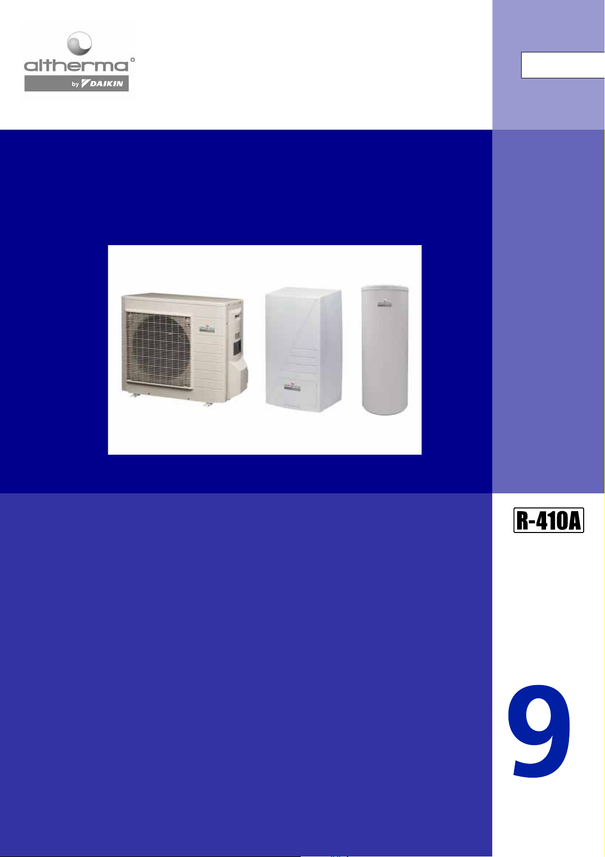
Altherma
ERYQ005-007A
EKHBH007A / EKHBX007A
EKSWW150-300
Page 2

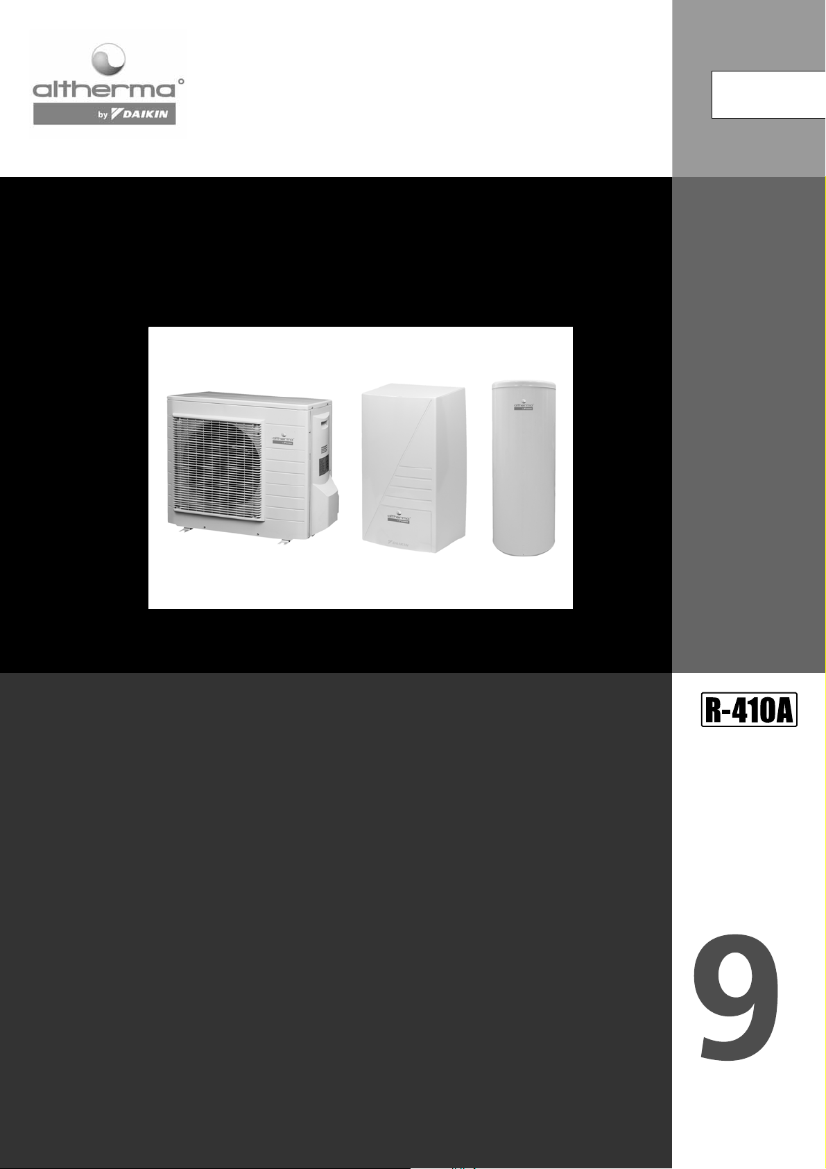
Altherma
ERYQ005-007A
EKHBH007A / EKHBX007A
EKSWW150-300
“ The present publication is drawn up by way of
information only and does not constitute an offer binding
upon Daikin Europe N.V.. Daikin Europe N.V. has compiled
the content of this publication to the best of its
knowledge. No express or implied warranty is given for
the completeness, accuracy, reliability or fitness for
particular purpose of its content and the products and
services presented therein. Specifications are subject to
change without prior notice. Daikin Europe N.V. explicitly
rejects any liability for any direct or indirect damage, In the
broadest sense, arising from or related to the use and/or
interpretation of this publication. All content is
copyrighted by Daikin Europe N.V..”
Zandvoordestraat 300
B - 8400 Ostend Belgium
www.daikineurope.com
ISO14001 assures an effective environmental
management system in order to help protect
human health and the environment from
potential impact of our activities, products and
services and to assist in maintaining and
improving the quality of the environment.
Daikin Europe N.V. is approved by LRQA for its
Quality Management System in accordance
with the ISO9001 standard. ISO9001 pertains
to quality assurance regarding design,
development, manufacturing as well as to
services related to the product.
Daikin units comply with the European
regulations that guarantee the safety of the
product.
EEDE06- 9
EEDE06-9 - 07/2006
Printed in Belgium by Goekint Graphics
Page 3
technical data
EEDE06-9
Altherma
ERYQ005-007A
EKHBH007A / EKHBX007A
EKSWW150-300
Page 4
• Chillers • R-410A • ALTHERMA
ChilleAltherAltherR-410A
Cooling only
Heating only
Heat pump
4
• Altherma • Chillers
Page 5

• Outdoor units • R-410A • ERYQ
TABLE OF CONTENTS
ERYQ
1Features . . . . . . . . . . . . . . . . . . . . . . . . . . . . . . . . . . . . . . . . . . . . . . . . . . . . . . . . . . . . . 6
2 Specifications . . . . . . . . . . . . . . . . . . . . . . . . . . . . . . . . . . . . . . . . . . . . . . . . . . . . . . . 7
Nominal Capacity and Nominal Input . . . . . . . . . . . . . . . . . . . . . . . . . . . . . . . 7
. . . . . . . . . . . . . . . . . . . . . . . . . . . . . . . . . . . . . . . . . . . . . . . . . . . . . . . . . . . . . . . . . . . . . . . 7
Technical Specifications . . . . . . . . . . . . . . . . . . . . . . . . . . . . . . . . . . . . . . . . . . . . . 7
Electrical Specifications . . . . . . . . . . . . . . . . . . . . . . . . . . . . . . . . . . . . . . . . . . . . . 9
3 Capacity tables . . . . . . . . . . . . . . . . . . . . . . . . . . . . . . . . . . . . . . . . . . . . . . . . . . . . 10
Cooling/Heating capacity tables . . . . . . . . . . . . . . . . . . . . . . . . . . . . . . . . . . . . 10
4 Dimensional drawing & centre of gravity . . . . . . . . . . . . . . . . . . . . . . . 11
Dimensional drawing . . . . . . . . . . . . . . . . . . . . . . . . . . . . . . . . . . . . . . . . . . . . . . . . 11
Centre of gravity . . . . . . . . . . . . . . . . . . . . . . . . . . . . . . . . . . . . . . . . . . . . . . . . . . . . 12
5 Piping diagram. . . . . . . . . . . . . . . . . . . . . . . . . . . . . . . . . . . . . . . . . . . . . . . . . . . . . 13
6 Wiring diagram. . . . . . . . . . . . . . . . . . . . . . . . . . . . . . . . . . . . . . . . . . . . . . . . . . . . . 14
Wiring diagram . . . . . . . . . . . . . . . . . . . . . . . . . . . . . . . . . . . . . . . . . . . . . . . . . . . . . . 14
External connection diagram . . . . . . . . . . . . . . . . . . . . . . . . . . . . . . . . . . . . . . . . 15
7 Sound data. . . . . . . . . . . . . . . . . . . . . . . . . . . . . . . . . . . . . . . . . . . . . . . . . . . . . . . . . 16
Sound pressure spectrum . . . . . . . . . . . . . . . . . . . . . . . . . . . . . . . . . . . . . . . . . . . 16
8 Operation range . . . . . . . . . . . . . . . . . . . . . . . . . . . . . . . . . . . . . . . . . . . . . . . . . . . 18
• Altherma • Outdoor units
5
Page 6
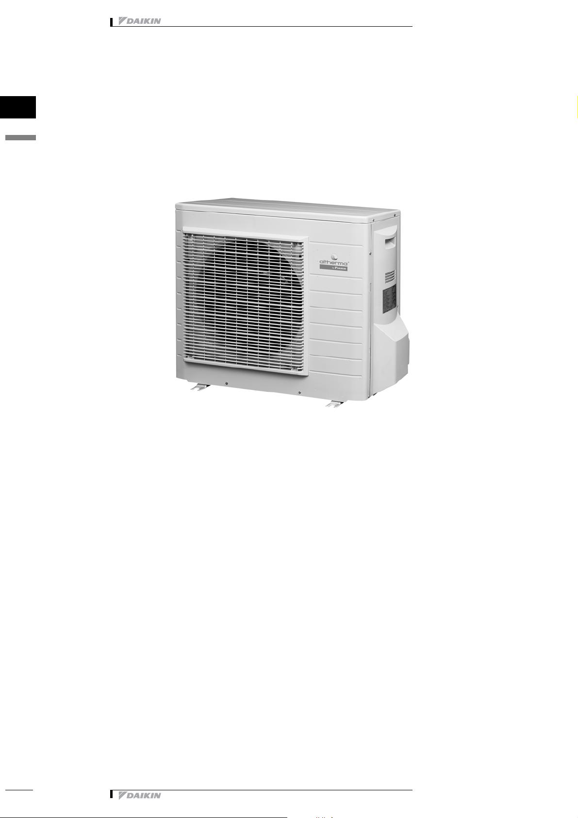
1 Features
Outdoor uni AlthermaERYQR-410A
• Cost effective alternative to a fossil fuel boiler
• Low energy bills and low CO2 emissions
1
1
• Outdoor units • R-410A • ERYQ
• Easy to install
• Total solution for year round comfort
6
• Altherma • Outdoor units
Page 7
• Outdoor units • R-410A • ERYQ
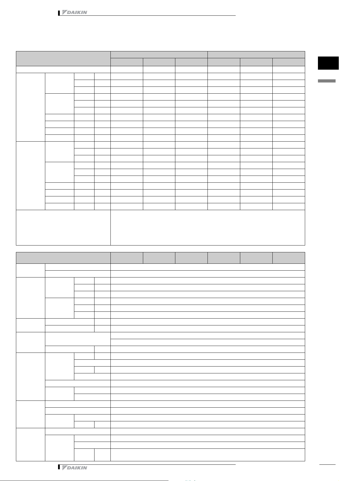
2 Specifications
2-1 NOMINAL CAPACITY AND
NOMINAL INPUT
Indoor Units EKHBH007A* EKHBH007A* EKHBH007A* EKHBX007A* EKHBX007A* EKHBX007A*
Condition 1 Heating
capacity
Cooling
capacity
Heating PI Nominal kW 1.26 1.58 2.08 1.26 1.58 2.08
Cooling PI Nominal kW - - - 2.16 2.59 2.75
COP Nominal - 4.56 4.34 4.05 4.56 4.34 4.05
EER Nominal - - - - 2.37 2.26 2.21
Condition 2 Heating Minimum kW 3.87 3.87 3.87 3.87 3.87 3.87
Cooling Minimum kW - - - 4.82 4.82 4.82
Heating PI Nominal kW 1.58 1.95 2.54 1.58 1.95 2.54
Cooling PI Nominal kW - - - 2.16 2.59 2.75
COP Nominal - 3.18 3.13 3.00 3.18 3.13 3.00
EER Nominal - - - - 3.33 3.15 3.04
Notes *Condition 1
Minimum kW 4.36 4.36 4.36 4.36 4.36 4.36
Nominal kW 5.75 6.84 8.43 5.75 6.84 8.43
Maximum kW 7.45 8.79 9.58 7.45 8.79 9.58
Minimum kW - - - 3.67 3.67 3.67
NominalkW- - - 5.125.866.08
Maximum kW - - - 5.12 6.13 7.10
Nominal kW 5.03 6.10 7.64 5.03 6.10 7.64
Maximum kW 6.68 7.98 8.76 6.68 7.98 8.76
NominalkW- - - 7.208.168.37
Maximum kW - - - 7.20 8.50 8.91
ERYQ005A ERYQ006A ERYQ007A ERYQ005A ERYQ006A ERYQ007A
- cooling Ta 35°C - LWE 7°C
- heating Ta DB/WB 7°C/6°C - LWC 35°C (DT = 5°C)
* Condition 2
- cooling Ta 35°C - LWE 18°C (DT = 5°C)
- heating Ta DB/WB 7°C/6°C - LWC 45°C (DT = 5°C)
EKHBH* EKHBX*
1
2
2-2 TECHNICAL SPECIFICATIONS
Casing Colour Ivory white
Material Polyester painted galvanised steel
Dimensions Unit Height mm 797
Width mm 960
Depth mm 390
Packing Height mm 735
Width mm 825
Depth mm 300
Weight Unit kg 56
Packed Unit kg 61
Packing Material EPS
Weight kg 5
Heat
Exchanger
Fan Type Propeller
Compressor Quantity 1
Dimensions Length mm 845
Nr of Rows 2
Fin Pitch mm 1.8
Nr of Stages 32
Tube type Hi-Xa(8)
Fin Type WF fin
Treatment Anti-corrosion treatment (PE)
Quantity 1
Motor Quantity 1
Output W 53
Motor Model 2YC63BXD#C
Type Hermetically sealed swing compressor
Motor
Output
W 1920
ERYQ005A
(+ EKHBH)
ERYQ006A
(+ EKHBH)
ERYQ007A
(+ EKHBH)
Carton
ERYQ005A
(+ EKHBX)
ERYQ006A
(+ EKHBX)
ERYQ007A
(+ EKHBX)
• Altherma • Outdoor units
7
Page 8
• Outdoor units • R-410A • ERYQ
2 Specifications
1
2
ERYQ005A
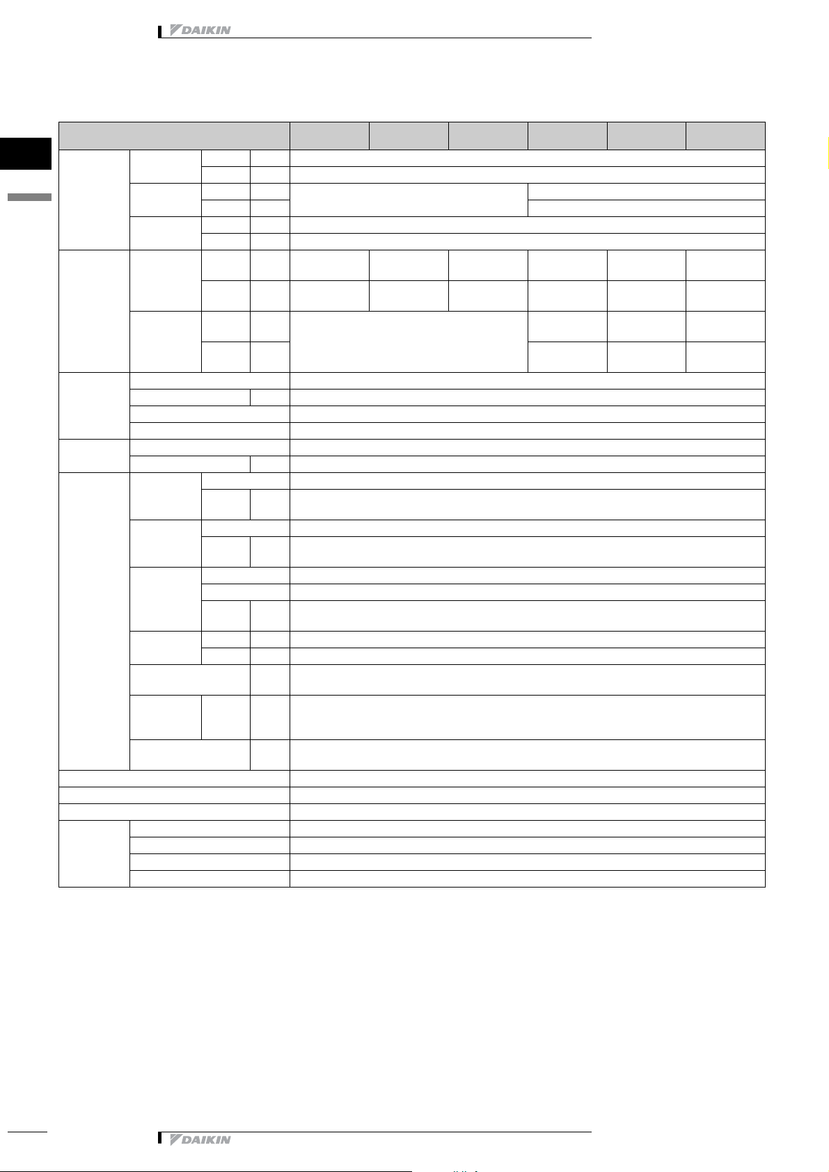
2-2 TECHNICAL SPECIFICATIONS
Operation
Range
Sound Level
(nominal)
Refrigerant Type R-410A
Refrigerant Oil Type FVC50K
Piping
connections
Defrost Method Reverse cycle
Defrost Control Sensor for outdoor heat exchanger temperature
Capacity Control Method Inverter controlled
Standard
Accessories
Heating Min °CWB -20
Max °CWB 25
Cooling Min °CDB 7
Max °CDB 20
Sanitary water Min °CDB -20
Max °CDB 43
Heating Sound
Power
Sound
Pressure
Cooling Sound
Power
Sound
Pressure
Charge kg 1.7
Control Expansion valve(electronic type)
Nr of Circuits 1
Charged Volume l 0.75
Liquid (OD) Type Flare connection
Diameter
(OD)
Gas Type Flare connection
Diameter
(OD)
Drain Quantity 1
Type Socket
Diameter
(OD)
Piping Length Minimum m 3
Maximum m 30
Additional Refrigerant
Charge
Installation
height
difference
Max. internunit level
difference
Item Installation manual
Quantity 1
Item Drain plug
Quantity 1
Maximum m 15
dBA646466646466
dBA484852484852
dBA 63 64 66
dBA 47 47 53
mm 6,35
mm 15,9
mm 18
kg/m 0.02 IF > 10m
m20
(+ EKHBH)
ERYQ006A
(+ EKHBH)
ERYQ007A
(+ EKHBH)
ERYQ005A
(+ EKHBX)
ERYQ006A
(+ EKHBX)
ERYQ007A
(+ EKHBX)
8
• Altherma • Outdoor units
Page 9
• Outdoor units • R-410A • ERYQ
2 Specifications
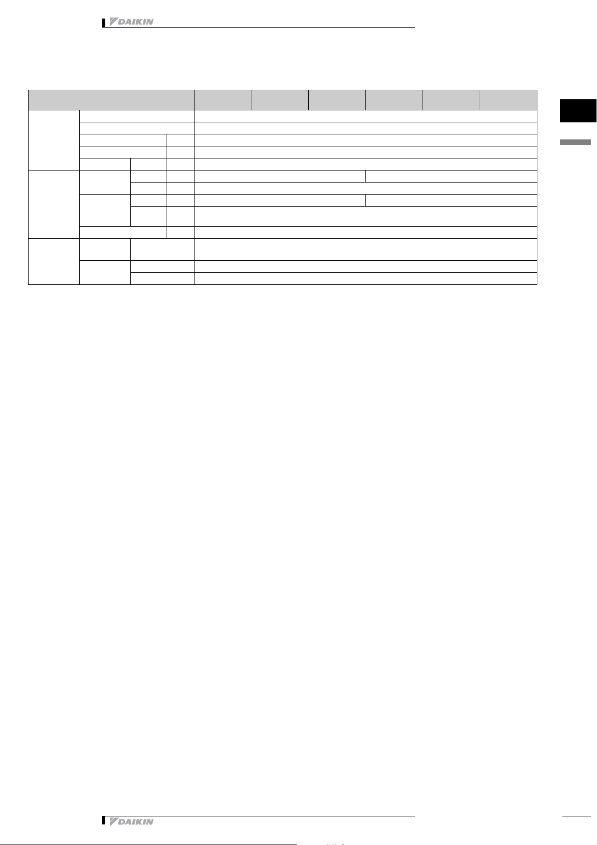
2-3 ELECTRICAL SPECIFICATIONS
Power Supply Name V1
Phase 1˜
Frequency Hz 50
Voltage V 220-440
Voltage range Maximum V +10%
Current Starting
Current
Maximum
running
Current
Recomended fuses A 20
Wiring
connections
For Power
Supply
For connection
with indoor
Cooling A 11
Heating A 11
Cooling A 16.25
Heating A 18
Quantity 3
Quantity 4
Remark Included eart h wiring
ERYQ005A
(+ EKHBH)
ERYQ006A
(+ EKHBH)
ERYQ007A
(+ EKHBH)
ERYQ005A
(+ EKHBX)
ERYQ006A
(+ EKHBX)
ERYQ007A
(+ EKHBX)
1
2
• Altherma • Outdoor units
9
Page 10
• Outdoor units • R-410A • ERYQ
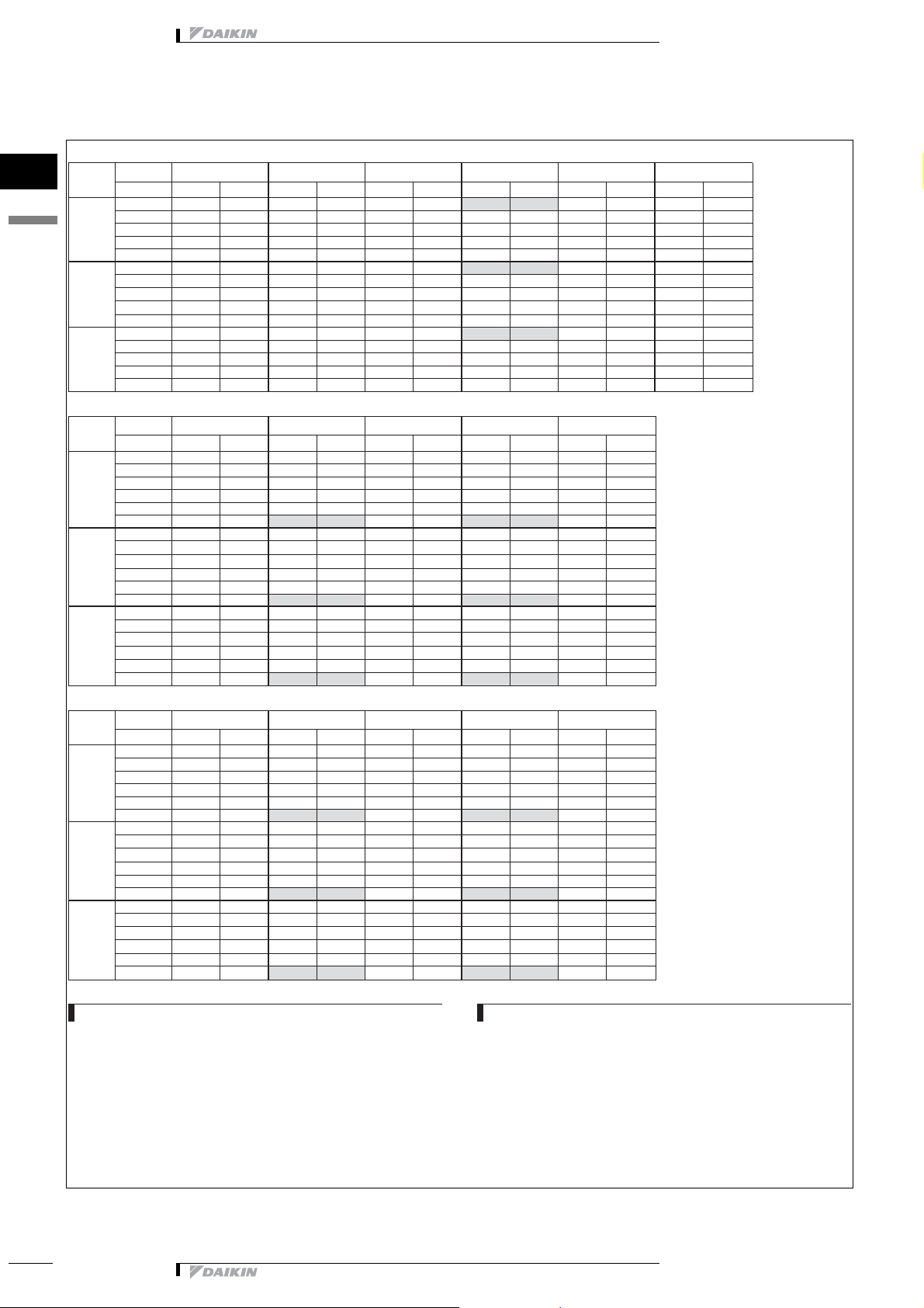
3 Capacity tables
3 - 1 Cooling/Heating capacity tables
COOLING
Model
1
3
HEATING (Peak values)
HEATING (integrated values*)
Tamb (°C) 20 25 30 35 40 43
LWE (°C)
CC PI CC PI CC PI CC PI CC PI CC PI
7 6.01 1.56 5.73 1.75 5.43 1.95 5.12 2.16 4.80 2.39 4.59 2.53
11 6.81 1.57 6.50 1.77 6.17 1.98 5.83 2.21 5.30 2.32 4.98 2.38
005
13 7.23 1.57 6.90 1.78 6.56 2.00 6.20 2.23 5.56 2.28 5.18 2.30
16 7.88 1.56 7.54 1.78 7.17 2.01 6.79 2.26 5.95 2.22 5.46 2.18
20 8.80 1.55 8.42 1.79 8.03 2.03 7.63 2.29 6.48 2.13 5.82 1.99
7 7.15 2.05 6.84 2.28 6.50 2.52 6.13 2.77 5.35 2.68 4.89 2.59
11 8.09 2.09 7.73 2.34 7.34 2.59 6.94 2.87 5.84 2.62 5.21 2.43
006
13 8.57 2.11 8.20 2.36 7.79 2.63 7.36 2.91 6.09 2.59 5.36 2.34
16 9.33 2.13 8.92 2.40 8.49 2.68 8.03 2.97 6.46 2.53 5.57 2.20
20 10.4 2.16 9.9 2.44 9.48 2.73 8.99 3.04 6.96 2.44 5.82 1.99
7 8.24 2.43 7.90 2.68 7.52 2.94 7.10 3.23 5.68 2.86 4.87 2.59
11 9.26 2.49 8.87 2.76 8.45 3.05 7.79 3.31 6.12 2.80 5.18 2.43
007
13 9.79 2.52 9.38 2.80 8.93 3.10 8.14 3.36 6.34 2.77 5.33 2.35
16 10.6 2.57 10.17 2.86 9.69 3.17 8.68 3.41 6.67 2.71 5.55 2.20
20 11.7 2.63 11.3 2.94 10.75 3.26 9.39 3.48 7.09 2.61 5.80 1.99
Model
LWC 30 35 40 45 50
Tamb
HC PI HC PI HC PI HC PI HC PI
-15 3.93 1.48 3.67 1.59 3.47 1.71 3.33 1.84 3.25 1.99
-10 4.65 1.52 4.32 1.65 4.07 1.79 3.89 1.94 3.78 2.10
005
-7 5.14 1.54 4.77 1.68 4.49 1.83 4.28 1.99 4.15 2.16
-2 6.06 1.57 5.62 1.72 5.28 1.88 5.03 2.06 4.87 2.25
2 6.89 1.57 6.38 1.74 6.00 1.91 5.72 2.11 5.53 2.31
7 8.03 1.57 7.45 1.75 7.00 1.94 6.68 2.15 6.47 2.37
-15 4.87 1.82 4.62 1.94 4.43 2.08 4.30 2.23 4.24 2.40
-10 5.67 1.88 5.34 2.02 5.09 2.18 4.92 2.36 4.82 2.55
006
-7 6.21 1.91 5.83 2.07 5.55 2.24 5.35 2.42 5.23 2.63
-2 7.23 1.95 6.77 2.13 6.42 2.32 6.17 2.52 6.02 2.75
2 8.14 1.97 7.61 2.16 7.21 2.37 6.92 2.59 6.74 2.83
7 9.40 1.98 8.79 2.19 8.32 2.42 7.98 2.66 7.78 2.92
-15 5.42 2.06 5.16 2.19 4.97 2.34 4.86 2.51 4.80 2.70
-10 6.27 2.13 5.93 2.29 5.68 2.46 5.51 2.65 5.42 2.86
007
-7 6.84 2.17 6.46 2.34 6.17 2.53 5.97 2.73 5.86 2.95
-2 7.92 2.22 7.45 2.41 7.10 2.62 6.85 2.85 6.70 3.10
2 8.9 2.26 8.35 2.46 7.93 2.69 7.65 2.93 7.47 3.20
7 10.2 2.28 9.58 2.51 9.10 2.76 8.76 3.02 8.56 3.31
Model
LWC 30 35 40 45 50
Tamb
HC PI HC PI HC PI HC PI HC PI
-15 3.50 1.40 3.27 1.51 3.09 1.62 2.97 1.75 2.89 1.89
-10 4.14 1.45 3.85 1.56 3.62 1.70 3.46 1.84 3.36 2.00
005
-7 4.52 1.45 4.20 1.58 3.95 1.72 3.77 1.87 3.65 2.03
-2 5.27 1.46 4.89 1.60 4.59 1.75 4.38 1.92 4.24 2.10
2 5.92 1.45 5.49 1.60 5.16 1.76 4.92 1.94 4.76 2.13
7 8.03 1.57 7.45 1.75 7.00 1.94 6.68 2.15 6.47 2.37
-15 4.34 1.73 4.11 1.85 3.94 1.98 3.83 2.12 3.77 2.28
-10 5.04 1.79 4.75 1.92 4.53 2.07 4.38 2.24 4.29 2.42
006
-7 5.46 1.80 5.13 1.94 4.88 2.10 4.71 2.28 4.60 2.47
-2 6.29 1.81 5.89 1.98 5.59 2.15 5.37 2.35 5.23 2.56
2 7.00 1.81 6.55 1.99 6.20 2.18 5.96 2.38 5.80 2.61
7 9.40 1.98 8.79 2.19 8.32 2.42 7.98 2.66 7.78 2.92
-15 4.82 1.96 4.59 2.08 4.43 2.23 4.32 2.39 4.27 2.56
-10 5.58 2.03 5.28 2.17 5.06 2.34 4.91 2.52 4.82 2.72
007
-7 6.02 2.04 5.69 2.20 5.43 2.37 5.26 2.57 5.15 2.78
-2 6.89 2.07 6.48 2.25 6.17 2.44 5.96 2.65 5.83 2.88
2 7.6 2.08 7.18 2.27 6.82 2.47 6.58 2.70 6.43 2.94
7 10.2 2.28 9.58 2.51 9.10 2.76 8.76 3.02 8.56 3.31
* The integrated heating capacity and power
input, is the average heating capacity and
power input during 1 cycle. (from end of
defrost till end of the next defrost).
4TW56712-1A
SYMBOLS
CC : Cooling capacity at maximum operating frequency, measured acc.
HC : Heating capacity at maximum operating frequency, measured acc.
PI : Power input (kW)
LWE : Leaving Water Evaporator temperature (°C)
LWC : Leaving Water Condensor temperature (°C)
Tamb : Ambient temperature (°C) RH=85%
10
Eurovent 6/C/003-2006 (kW)
Eurovent 6/C/003-2006 (kW)
• Altherma • Outdoor units
NOTES
1 Cooling capacity
Capacity is according to Eurovent rating standard 6/C/003-2006 and valid for
chilled water range Dt = 3∼8°C
2 Heating capacity
Capacity is according to Eurovent rating standard 6/C/003-2006 and valid for
chilled water range Dt = 3∼8°C
3 Power input
Power input is total input according to Eurovent rating standard 6/C/003-2006
Page 11
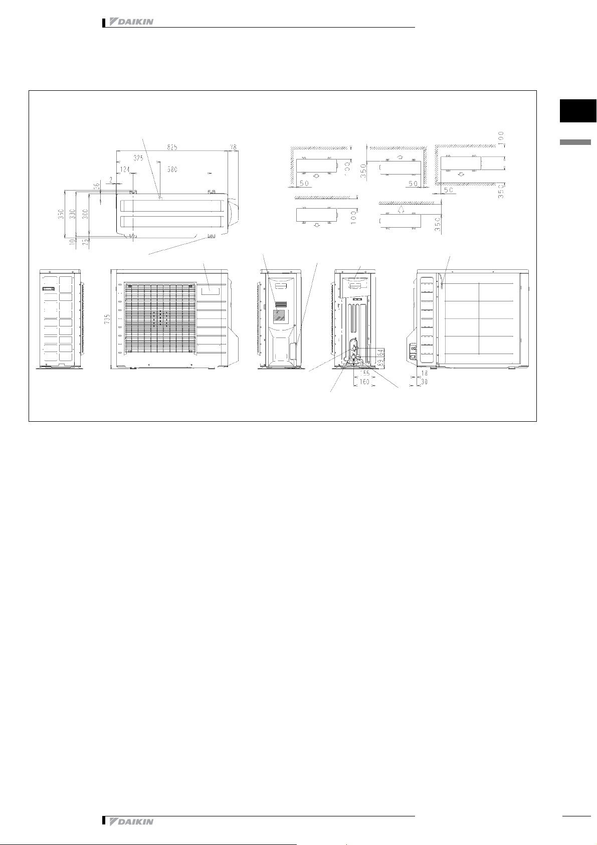
• Outdoor units • R-410A • ERYQ
4 Dimensional drawing & centre of gravity
4 - 1 Dimensional drawing
ERYQ
(I.D. J 15.9 hose for connection)
4 x holes for anchor bolts (M8 or M10)
Drain outlet
Brand name label
Name plate
Wiring inlet
Liquid stop valve
(J6.4 CuT)
Minimum space for air passage
In case of removing stop valve cover
Terminal strip with earth
terminal
Service port
Gas stop valve
(J15.9 CuT)
Wall height on air outlet side =
less than 1200
Outdoor air thermistor
unit (mm)
1
4
3D051658B
• Altherma • Outdoor units
11
Page 12

• Outdoor units • R-410A • ERYQ
4 Dimensional drawing & centre of gravity
4 - 2 Centre of gravity
ERYQ
1
4
The position of foundation bolt
4D042258G
12
• Altherma • Outdoor units
Page 13

• Outdoor units • R-410A • ERYQ
5 Piping diagram
ERYQ
Outdoor unit
Heat
exchanger
thermistor
Muffler
Muffler
Propeller fan
Discharge pipe
thermistor
Heat exchanger
Four way valve
on : heating
Compressor
Outdoor temperature thermistor
Capillary tube 1
Capillary tube 2
Capillary tube 3
Capillary tube 4
Accumulator
Muffler with
filter
Filter
Filter
Muffler with filter
Motor operated
valve
Liquid stop valve
Gas stop valve with
service port
1
5
Refrigerant flow
Cooling
Heating
Field piping
Field piping
3D052750A
• Altherma • Outdoor units
13
Page 14

6 Wiring diagram
6 - 1 Wiring diagram
ERYQ
1
6
Power supply
To indoor unit
Sheet metal
Indoor
g
Field wiring
• Outdoor units • R-410A • ERYQ
Z1C∼Z7C : Ferrite core
X1M, X2M : Terminal strip
Y1E : Electronic expansion valve coil
V2, V3, V5, V9, V100 : Varistor
SA2 : Surge arrester
FU1, FU2, FU3: : Fuse
AC1, AC2
U, V, W, X11A, X12A
E1, E2
HR1, HR2 : Connector
MRM10, MRM20
MRC/W : Magnetic relay
R1T∼R3T : Thermistor
S2∼S102 : Connector
LEDA : Pilot lamp
L : Live
N : Neutral
SW1 : Forced operation on/off switch SW (SW1)
SW4 : Local setting SW (SW4)
M1C : Compressor motor
M1F : Fan motor
L1R : Reactor
(outdoor)
Outdoor
Q1L : Overload protector
PM1 : Power module
PCB1,2 : Printed circuit board
Y1R : Reversing solenoide valve coil
Sheet metal : Terminal strip fixed plate
(discharge)
(Condenser)
3D052296B
14
• Altherma • Outdoor units
Page 15

• Outdoor units • R-410A • ERYQ
6 Wiring diagram
6 - 2 External connection diagram
EKHB-A
Power supply
Unit power supply: 230V + earth
Backup heater power supply (3/6/9kW): 400V or
230V + earth
3 core
Standard parts
Outdoor unit
X1M:L-N-Earth
For more details please check unit wiring
diagram
1
6
Optional power supply
Booster heater power supply (3kW): 400V or 230V
+ earth
Optional parts
Sanitary tank
Power supply booster
heater
Q2L - Clixon booster
heater
R5T - Thermistor water
temperature
3 core
5 core
230V or 400V
2 core
Signal
Thermistor cable
Note: min. distance
to power cable =
3cm
3 or 4 core
X1M:7-8-Earth
X2M:1-2-3-Earth
4 core
X1M:9-10-11-Earth
NO valve:
NC valve:
Indoor unit
User interface
4 core
2 core
2 core
Field supply
Room thermostat
A3P (optional)
2 way valve
M2S (EKHBX Units)
for cooling mode
3 way valve
M3S (when EKSWW is installed)
selection sanitary-floorheating
3TW56719-6
• Altherma • Outdoor units
15
Page 16

• Outdoor units • R-410A • ERYQ
3TW56717-1
Sound pressure level (dB)
Octave band center frequency (Hz)
ERYQ006ABV3
Cooling
NOTES
1 Data is valid at free field condition (measured in a
semi-anachoic room)
2 dB(A) = A-weighted sound power level (A-scale
according to IEC)
3 Reference acoustic pressure 0dB = 20μPa
4 If sound is measured under actual installation
conditions, the measured value will be higher due to
environmental noise and sound reflections.
Location of microphone
Microphone
Coil
3TW56717-2
Sound pressure level (dB)
Octave band center frequency (Hz)
ERYQ005ABV3
Heating
NOTES
1 Data is valid at free field condition (measured in a
semi-anachoic room)
2 dB(A) = A-weighted sound power level (A-scale
according to IEC)
3 Reference acoustic pressure 0dB = 20μPa
4 If sound is measured under actual installation
conditions, the measured value will be higher due to
environmental noise and sound reflections.
Location of microphone
Microphone
Coil
7 Sound data
7 - 1 Sound pressure spectrum
ERYQ005ABV3
Cooling
1
7
Sound pressure level (dB)
3TW56717-1
Octave band center frequency (Hz)
NOTES
1 Data is valid at free field condition (measured in a
semi-anachoic room)
2 dB(A) = A-weighted sound power level (A-scale
according to IEC)
3 Reference acoustic pressure 0dB = 20μPa
4 If sound is measured under actual installation
conditions, the measured value will be higher due to
environmental noise and sound reflections.
ERYQ007ABV3
Cooling
Sound pressure level (dB)
Coil
Microphone
Location of microphone
3TW56717-1
NOTES
1 Data is valid at free field condition (measured in a
semi-anachoic room)
2 dB(A) = A-weighted sound power level (A-scale
according to IEC)
3 Reference acoustic pressure 0dB = 20μPa
16
4 If sound is measured under actual installation
conditions, the measured value will be higher due to
environmental noise and sound reflections.
Octave band center frequency (Hz)
Coil
Location of microphone
• Altherma • Outdoor units
Microphone
Page 17

• Outdoor units • R-410A • ERYQ
7 Sound data
7 - 1 Sound pressure spectrum
ERYQ006ABV3
Heating
Sound pressure level (dB)
3TW56717-2
NOTES
1 Data is valid at free field condition (measured in a
semi-anachoic room)
2 dB(A) = A-weighted sound power level (A-scale
according to IEC)
3 Reference acoustic pressure 0dB = 20μPa
4 If sound is measured under actual installation
conditions, the measured value will be higher due to
environmental noise and sound reflections.
Octave band center frequency (Hz)
Coil
Location of microphone
Microphone
ERYQ007ABV3
Heating
Sound pressure level (dB)
3TW56717-2
NOTES
1 Data is valid at free field condition (measured in a
semi-anachoic room)
2 dB(A) = A-weighted sound power level (A-scale
according to IEC)
3 Reference acoustic pressure 0dB = 20μPa
4 If sound is measured under actual installation
conditions, the measured value will be higher due to
environmental noise and sound reflections.
Octave band center frequency (Hz)
1
7
Coil
Microphone
Location of microphone
• Altherma • Outdoor units
17
Page 18

• Outdoor units • R-410A • ERYQ
8 Operation range
1
8
Outdoor temp. (°CDB)
Cooling mode
Leaving evaporator water temperature (°C)
Outdoor temp. (°CDB)
Heating mode
Sanitary mode
Leaving condenser water temperature (°C)
Outdoor temp. (°CDB)
: Booster heater operation
only
Leaving condenser water temperature (°C)
18
4TW56713-1A
• Altherma • Outdoor units
Page 19

• Indoor units • R-410A • EKHBH / EKHBX
TABLE OF CONTENTS
EKHBH / EKHBX
1Features . . . . . . . . . . . . . . . . . . . . . . . . . . . . . . . . . . . . . . . . . . . . . . . . . . . . . . . . . . . . 20
2 Specifications . . . . . . . . . . . . . . . . . . . . . . . . . . . . . . . . . . . . . . . . . . . . . . . . . . . . . . 21
Technical Specifications . . . . . . . . . . . . . . . . . . . . . . . . . . . . . . . . . . . . . . . . . . . . 21
Electrical Specifications . . . . . . . . . . . . . . . . . . . . . . . . . . . . . . . . . . . . . . . . . . . . 23
3Options . . . . . . . . . . . . . . . . . . . . . . . . . . . . . . . . . . . . . . . . . . . . . . . . . . . . . . . . . . . . . 24
4 Dimensional drawing & centre of gravity . . . . . . . . . . . . . . . . . . . . . . . 25
Dimensional drawing . . . . . . . . . . . . . . . . . . . . . . . . . . . . . . . . . . . . . . . . . . . . . . . . 25
5 Piping diagram. . . . . . . . . . . . . . . . . . . . . . . . . . . . . . . . . . . . . . . . . . . . . . . . . . . . . 26
6 Wiring diagram. . . . . . . . . . . . . . . . . . . . . . . . . . . . . . . . . . . . . . . . . . . . . . . . . . . . . 27
Wiring diagram . . . . . . . . . . . . . . . . . . . . . . . . . . . . . . . . . . . . . . . . . . . . . . . . . . . . . . 27
External connection diagram . . . . . . . . . . . . . . . . . . . . . . . . . . . . . . . . . . . . . . . . 29
7 Hydraulic performance. . . . . . . . . . . . . . . . . . . . . . . . . . . . . . . . . . . . . . . . . . . . 30
Static pressure drop unit . . . . . . . . . . . . . . . . . . . . . . . . . . . . . . . . . . . . . . . . . . . . 30
• Altherma • Indoor units
19
Page 20

1 Features
Indoor unit AlthermaEKHBH / EKH R-410A
• Cost effective alternative to a fossil fuel boiler
• Low energy bills and low CO2 emissions
2
1
• Indoor units • R-410A • EKHBH / EKHBX
• Easy to install
• Total solution for year round comfort
20
• Altherma • Indoor units
Page 21

• Indoor units • R-410A • EKHBH / EKHBX
2 Specifications
EKHBH007A
2-1 TECHNICAL SPECIFICATIONS
Outdoor units ERYQ005A ERYQ006A ERYQ007A ERYQ005A ERYQ006A ERYQ007A
Nominal input (Indoor only) W 230
Casing Colour RAL9010
Material Polyester painted galvanised steel
Dimensions Packing Height mm 1225
Width mm 660
Depth mm 595
Unit Height mm 895 936
Width mm 487 487
Depth mm 361 461
Weight Unit kg 55 65
Packed Unit kg 65 75
Packing Material EPS
Weight kg 10
Main
components
Pump Nominal ESP
Main
components
Water side
Heat
exchanger
Main
components
Water circuit Piping connections
Pump Type Water cooled
Nr. of speed 3
unit
Pump Power
Water side
Heat
exchanger
Water flow
rate Nom.
Water side
Heat
exchanger
Expansion
vessel
Water filter Diameter
diameter
Piping inch 1"MBSP
Safety valve bar 3
Manometer Yes
Drain valve / Fill valve Yes
Shut off valve Yes
Air purge valve Yes
Cooling kPa 49.9 46.5 44.4
Heating kPa 46.5 40.1 29.0 46.5 40.1 29.0
W130
input
Type Brazed plate
Qty 1
Water
volume
Water
flow rate
Min.
Cooling l/min 14.7 16.5 17.6
Heating l/min 16.5 19.6 24.2 16.5 19.6 24.2
Insulation material Polyurethane foam
Volume l 10
Max.
water
pressure
Pre
pressure
perforations
Material Brass
l0.67
l/min 12
bar 3
bar 1
mm 1
inch 1"MBSP
(+ERYQ005A)
EKHBH007A
(+ERYQ006A)
EKHBH007A
(+ERYQ007A)
Wood
Carton
PS(straps)
EKHBX007A
(+ERYQ005A)
EKHBX007A
(+ERYQ006A)
EKHBX007A
(+ERYQ007A)
2
2
• Altherma • Indoor units
21
Page 22

• Indoor units • R-410A • EKHBH / EKHBX
2 Specifications
2
2
2-1 TECHNICAL SPECIFICATIONS
Refrigerant
Circuit
Sound Level Sound Pressure dBA 27
Operation
range
Notes The sound pressure level is measured via a microphone at a certain distance from the unit. It is a relative value,
Gas side diameter mm 15,9
Liquid side diameter mm (2)
Waterside Cooling °C 7 ˜ 20
Heating °C 30 ˜ 55
EKHBH007A
(+ERYQ005A)
EKHBH007A
(+ERYQ006A)
depending on the distance and acoustic environment.
EKHBH007A
(+ERYQ007A)
ERYQ = 6.35 mm
EKHB = 9.52 mm (flare connection)
EKHBX007A
(+ERYQ005A)
EKHBX007A
(+ERYQ006A)
EKHBX007A
(+ERYQ007A)
22
• Altherma • Indoor units
Page 23

• Indoor units • R-410A • EKHBH / EKHBX
2 Specifications
2-2 ELECTRICAL SPECIFICATIONS
Electric
heater
Electric
heater
Electric
heater
Electric
heater
Electric
heater
Electric
heater
Type 3V3
Power Supply Phase 1
Frequency
Voltage V 230
Current Running
Current
Type 6V3
Power Supply Phase 1
Frequency
Voltage V 230
Current Running
Current
Type 6W1
Power Supply Phase 3N
Frequency
Voltage V 400
Current Running
Current
Type 6T1
Power Supply Phase 3
Frequency
Voltage V 230
Current Running
Current
Type 9W1
Power Supply Phase 3N
Frequency
Voltage V 400
Current Running
Current
Type 9T1
Power Supply Phase 3
Frequency
Voltage V 230
Current Running
Current
EKHBH007A
(+ERYQ005A)
Hz 50
A13
Hz 50
A26
Hz 50
A8.6
Hz 50
A15
Hz 50
A13
Hz 50
A23
EKHBH007A
(+ERYQ006A)
EKHBH007A
(+ERYQ007A)
EKHBX007A
(+ERYQ005A)
EKHBX007A
(+ERYQ006A)
EKHBX007A
(+ERYQ007A)
2
2
• Altherma • Indoor units
23
Page 24

3 Options
Availability
2
3
EKHBX007A9T1
EKHBH007A9T1
EKHBX007A9W1
EKHBH007A9W1
• Indoor units • R-410A • EKHBH / EKHBX
3TW56719-5
EKHBX007A6T1
EKHBH007A6T1
EKHBX007A6W1
EKHBH007A6W1
EKHBX007A6V3
EKHBH007A6V3
EKHBX007A3V3
EKHBH007A3V3
24
Heating only model
Reversible model
Reference Description Number
Optional equipment for EKHB(H/X)007*
Available options
6T1 Back up heater 6kW 3∼230 V ⎯⎯⎯V ⎯⎯Factory mounted
6W1 Back up heater 6kW 3∼400V+N ⎯⎯V ⎯⎯⎯Factory mounted
6V3 Back up heater 6kW 1∼230 V ⎯ V ⎯⎯⎯⎯Factory mounted
3V3 Back up heater 3kW 1∼230 V V ⎯⎯⎯⎯⎯Factory mounted
• Altherma • Indoor units
9W1 Back up heater 9kW 3∼400V+N ⎯⎯⎯⎯V ⎯ Factory mounted
9T1 Back up heater 9kW 3∼230 V ⎯⎯⎯⎯⎯V Factory mounted
Available kits
EKSWW300Z2 Sanitary warm water tank 300 l 400 V ⎯⎯V ⎯ V ⎯ Kit
EKSWW200Z2 Sanitary warm water tank 200 l 400 V ⎯⎯V ⎯ V ⎯ Kit
EKSWW300V3 Sanitary warm water tank 300 l 230 V VVVVVVKit
EKSWW200V3 Sanitary warm water tank 200 l 230 V VVVVVVKit
EKSWW150V3 Sanitary warm water tank 150 l 230 V VVVVVVKit
EKWBSWW150 Wall bracket for EKSWW150V3 Kit
Page 25

• Indoor units • R-410A • EKHBH / EKHBX
4 Dimensional drawing & centre of gravity
4 - 1 Dimensional drawing
EKHBH-A
Minimum space for service & ventilation
Min. 200
AB
Setup 1 ≥ 200 ≥ 400
Setup 2 ≥ 350 ≥ 200
Min. 400
Center of gravity
j
1
Pump + switch for speed setting
j
2
Remocon
j
3
Water IN conection 1’’ M BSP
j
4
Water OUT connection 1’’ M BSP
j
5
Power supply intake (+ sanitary warm water tank)
j
6
Drain / fill valve
j
7
Air purge
j
8
Expansion vessel + nipple
j
9
Blow off valve
j
10
Pressure gauge
j
11
Water filter
j
12
Suction pipe connection J15.9 flare connection
j
13
Liquid pipe connection J 9.52 flare connection
j
14
Shut off valves (delivered with unit)
j
15
Thermistor connection (+ sanitary warm water tank)
j
16
Holes for fixation
j
17
Blow off drain
j
18
Switchbox connection terminals
j
19
Wallbracket
1’’ female BSP
1’’ male BSP
2
4
Service
door
Min. 100
(Closed) 361
(Open) 553
EKHBX-A
Minimum space for service & ventilation
Min. 200
3TW56714-1A
Service
door
Center of gravity
j
1
Pump + switch for speed setting
j
2
Remocon
j
3
Water IN conection 1’’ M BSP
j
4
Water OUT connection 1’’ M BSP
j
5
Power supply intake (+ sanitary warm water tank)
j
6
Drain / fill valve
j
7
Air purge
j
8
Expansion vessel + nipple
j
9
Blow off valve
j
10
Pressure gauge
j
11
Water filter
j
12
Suction pipe connection J15.9 flare connection
j
13
Liquid pipe connection J 9.52 flare connection
j
14
Shut off valves (delivered with unit)
j
15
Thermistor connection (+ sanitary warm water tank)
j
16
Holes for fixation
j
17
Blow off drain / drain of drainpan
j
18
Switchbox connection terminals
j
19
Wallbracket
Min. 400
AB
Setup 1 ≥ 200 ≥ 400
Setup 2 ≥ 350 ≥ 200
1’’ female BSP
1’’ male BSP
Min. 125
Dimensions wallbracket
(Closed) 461
(Open) 653
3TW56724-1A
• Altherma • Indoor units
25
Page 26

• Indoor units • R-410A • EKHBH / EKHBX
5 Piping diagram
2
5
EKHB-A
Refrigerant side
Outdoor unit
R4T Inlet water thermistor
R3T Refrigerant liquid side thermistor
R2T Outlet water backup heater thermistor
R1T Outlet water heat-exchanger thermistor
Cooling (EKHBX)
Heating (EKHBX + EKHBH)
Overview
Refr. out
Refr. in
Refr. in
Refr. out
Refrigerant
side
Evaporator
Condensor
Water side
Water inlet
Water outlet
Water side
Expansion
vessel
Pressure gauge
Air purge
Pump
Drain valve
Drain valve
Electric heater body
Filter
Option backup
heater
Safety valve
Drain
Flowswitch
Field installation
Shut off valve
Field installation
Shut off valve
Inlet
Outlet
O
Check valve
L
Flare connection
M
Screw connection
N
Flange connectionZPinched pipePSpinned pipe
3TW56715-1
26
• Altherma • Indoor units
Page 27

• Indoor units • R-410A • EKHBH / EKHBX
6 Wiring diagram
6 - 1 Wiring diagram
EKHBH/X-A3V3
Power supply
>> See note2 <<
Sanitary tank
Only for
EKSWW option
Only for
EKHB*00*A3V3
EKHBH/X-A6V3
Power supply
>>Seenote2<<
Outdoor unit
Outdoor unit
User interface
Wiring dependent
on model
Field wiring
Thermostat
On/Off
heating
cooling
supply from
PCB
Option
Wire colour
Only for
NO valve
NC valve
Notes:
1 This wiringdiagram only applies to the indoor unit.
2 Use oneand same dedicated power supply for indoor unit,outdoor unit and EKSWW option
3
:Field wiring
4
:Terminal strip :Connector :Terminal :Protective earth
5 Do notoperate the unit by short-circuiting protection devices Q1L,Q2L, S1L.
6 BLK: Black/ WHT: White / RED: Red / BLU:Blue / PINK: Pink / YLW: Yellow
BRN: Brown /GRY: Grey / GRN: Green / ORG: Orange / VIO: Violet
EKHB*00*A6V3
Only for
EKHB*00*A3V3
Only for EKSWW
option
model
F1B 20A
model
F2B 20A
Sanitary
tank
Only for EKSWWoption
Electric heater option fuse
EKSWW kit fuse
Sanitary tank
Only for EKSWWoption
2
6
Only for
EKHB*00*A3V3 or6V3
Only for EKSWW
V2S : Spark suppression 2
V1S : Spark suppression 1
FU1 : Fuse 3.15A T 250V
R1T (A2P) : Thermistor (air)
Q1DI : Earth leakage protector
Q2L : Thermal protector booster heater
Q1L : Thermal protector backup heater
TR1 : Transformer24V for PCB
R5T : SWWThermistor
R4T : Inletwater thermistor
R3T : Refrigerantliquid side thermistor
R2T : Outletwater backup heater thermistor
R1T (A1P) : Outlet waterheat-exchanger thermistor
S1L : Flowswitch
E4H : Booster heater
3V3
E3H : Backup heaterelement 3
E2H : Backup heaterelement 2
E1H : Backup heaterelement 1
M3S : 3 way valve floorheating / sanitary warm water
M2S : 2 way valve for cooling mode
M1P : Pump
K3M : Contactor boosterheater
K2M : Contactor backupheater Step 2
K1M : Contactor backupheater Step 1
F2B : Fuse booster heater
F1B : Fuse backup heater
A3P : Thermostat (field supply, PC = interval powercircuit)
A2P : Remocon PCB
A1P : Main PCB
option
3TW56716-4A
Sanitary tank
Only for
EKSWW option
User interface
NO valve
230V AC
supply from PCB
heating
cooling
Thermostat
On/Off
Wiring dependent
on model
Field wiring
NC valve
Option
Wire colour
• Altherma • Indoor units
Only for EKSWW
option
Electric heater option fuse
model
6V3
F1B 32A
EKSWW kit fuse
model
F2B 20A
Notes:
1 This wiringdiagram only applies to the indoor unit.
2 Use oneand same dedicated power supply for indoor unit,outdoor unit and EKSWW option
3
:Field wiring
4
:Terminal strip :Connector :Terminal :Protective earth
5 Do notoperate the unit by short-circuiting protection devices Q1L,Q2L, S1L.
6 BLK: Black/ WHT: White / RED: Red / BLU:Blue / PINK: Pink / YLW: Yellow
BRN: Brown /GRY: Grey / GRN: Green / ORG: Orange / VIO: Violet
Only for EKSWW
option
X1M : Terminal block
V2S : Spark suppression 2
V1S : Spark suppression 1
FU1 : Fuse 3.15A T 250V
R1T (A2P) : Thermistor (air)
Q1DI : Earth leakage protector
Q2L : Thermal protector booster heater
Q1L : Thermal protector backup heater
TR1 : Transformer24V for PCB
R5T : SWWThermistor
R4T : Inletwater thermistor
R3T : Refrigerantliquid side thermistor
R2T : Outletwater backup heater thermistor
R1T (A1P) : Outlet waterheat-exchanger thermistor
S1L : Flowswitch
E4H : Booster heater
E3H : Backup heaterelement 3
E2H : Backup heaterelement 2
E1H : Backup heaterelement 1
M3S : 3 way valve floorheating / sanitary warm water
M2S : 2 way valve for cooling mode
M1P : Pump
K4M : Contactor backupheater
K3M : Contactor boosterheater
K2M : Contactor backupheater Step 2
K1M : Contactor backupheater Step 1
F2B : Fuse booster heater
F1B : Fuse backup heater
A3P : Thermostat (field supply, PC = interval powercircuit)
A2P : Remocon PCB
A1P : Main PCB
3TW56716-5
27
Page 28

6 Wiring diagram
6 - 1 Wiring diagram
EKHBH/X-A6W1/9W1
Power supply
>> See note2 <<
2
6
Option
Sanitary tank
Only for
EKSWW*Z2
Option
Sanitary tank
Only for EKSWW*V3
EKHBH/X-A6T1/9T1
Power supply
>> See note2 <<
• Indoor units • R-410A • EKHBH / EKHBX
Outdoor unit
User interface
NO valve
230V AC
supply from PCB
heating
cooling
Thermostat
Outdoor unit
Wiring dependent
on model
Field wiring
On/Off
Option
Wire colour
NC valve
Notes:
1 This wiringdiagram only applies to the indoor unit.
2 Use oneand same dedicated power supply for indoor unit,outdoor unit and EKSWW option
3
:Field wiring
4
:Terminal strip :Connector :Terminal :Protective earth
5 Do notoperate the unit by short-circuiting protection devices Q1L,Q2L, S1L.
6 BLK: Black/ WHT: White / RED: Red / BLU:Blue / PINK: Pink / YLW: Yellow
BRN: Brown /GRY: Grey / GRN: Green / ORG: Orange / VIO: Violet
Electric heater option fuse
model
6W1 9W1
F1B 13A 16A
EKSWW kit fuse
model
F2B 20A
Sanitary tank
Only for EKSWWoption
Only for EKSWW
option
Sanitary tank
Only for EKSWWoption
Only for EKSWW
option
X1M : Terminal block
V2S : Spark suppression 2
V1S : Spark suppression 1
FU1 : Fuse 3.15A T 250V
R1T (A2P) : Thermistor (air)
Q1DI : Earth leakage protector
Q2L : Thermal protector booster heater
Q1L : Thermal protector backup heater
TR1 : Transformer24V for PCB
R5T : SWWThermistor
R4T : Inletwater thermistor
R3T : Refrigerantliquid side thermistor
R2T : Outletwater backup heater thermistor
R1T (A1P) : Outlet waterheat-exchanger thermistor
S1L : Flowswitch
E4H : Booster heater
E3H : Backup heaterelement 3
E2H : Backup heaterelement 2
E1H : Backup heaterelement 1
M3S : 3 way valve floorheating / sanitary warm water
M2S : 2 way valve for cooling mode
M1P : Pump
K4M : Contactor backupheater
K3M : Contactor boosterheater
K3M : Contactor boosterheater
K2M : Contactor backupheater Step 2
K1M : Contactor backupheater Step 1
F2B : Fuse booster heater
F1B : Fuse backup heater
A3P : Thermostat(Field supply)
A2P : Remocon PCB
A1P : Main PCB
3TW56716-2B
28
Sanitary tank
Only for
EKSWW option
User interface
NO valve
230V AC
supply from PCB
heating
cooling
Thermostat
Wiring dependent
on model
Field wiring
On/Off
NC valve
Option
Wire colour
• Altherma • Indoor units
Only for EKSWW
option
Electric heater option fuse
model
6T1 9T1
F1B 20A 32A
EKSWW kit fuse
model
Notes:
1 This wiringdiagram only applies to the indoor unit.
2 Use oneand same dedicated power supply for indoor unit,outdoor unit and EKSWW option
3
4
5 Do notoperate the unit by short-circuiting protection devices Q1L,Q2L, S1L.
6 BLK: Black/ WHT: White / RED: Red / BLU:Blue / PINK: Pink / YLW: Yellow
BRN: Brown /GRY: Grey / GRN: Green / ORG: Orange / VIO: Violet
F2B 20A
:Field wiring
:Terminal strip :Connector :Terminal :Protective earth
Only for EKSWW
option
X1M : Terminal block
V2S : Spark suppression 2
V1S : Spark suppression 1
FU1 : Fuse 3.15A T 250V
R1T (A2P) : Thermistor (air)
Q1DI : Earth leakage protector
Q2L : Thermal protector booster heater
Q1L : Thermal protector backup heater
TR1 : Transformer24V for PCB
R5T : SWWThermistor
R4T : Inletwater thermistor
R3T : Refrigerantliquid side thermistor
R2T : Outletwater backup heater thermistor
R1T (A1P) : Outlet waterheat-exchanger thermistor
S1L : Flowswitch
E4H : Booster heater
E3H : Backup heaterelement 3
E2H : Backup heaterelement 2
E1H : Backup heaterelement 1
M3S : 3 way valve floorheating / sanitary warm water
M2S : 2 way valve for cooling mode
M1P : Pump
K4M : Contactor backupheater
K3M : Contactor boosterheater
K2M : Contactor backupheater Step 2
K1M : Contactor backupheater Step 1
F2B : Fuse booster heater
F1B : Fuse backup heater
A3P : Thermostat(Field supply)
A2P : Remocon PCB
A1P : Main PCB
3TW56716-3B
Page 29

• Indoor units • R-410A • EKHBH / EKHBX
6 Wiring diagram
6 - 2 External connection diagram
EKHB-A
Power supply
Unit power supply: 230V + earth
Backup heater power supply (3/6/9kW): 400V or
230V + earth
Optional power supply
Booster heater power supply (3kW): 400V or 230V
+ earth
Optional parts
Sanitary tank
Power supply booster
heater
Q2L - Clixon booster
heater
R5T - Thermistor water
temperature
3 core
3 core
5 core
230V or 400V
2 core
Signal
Thermistor cable
Note: min. distance
to power cable =
3cm
3 or 4 core
Standard parts
Outdoor unit
X1M:L-N-Earth
X1M:7-8-Earth
X2M:1-2-3-Earth
4 core
X1M:9-10-11-Earth
NO valve:
NC valve:
Indoor unit
User interface
For more details please check unit wiring
diagram
Field supply
4 core
2 core
2 core
Room thermostat
A3P (optional)
2 way valve
M2S (EKHBX Units)
for cooling mode
3 way valve
M3S (when EKSWW is installed)
selection sanitary-floorheating
2
6
3TW56719-6
• Altherma • Indoor units
29
Page 30

• Indoor units • R-410A • EKHBH / EKHBX
7 Hydraulic performance
7 - 1 Static pressure drop unit
2
7
ESP = f (Flow)
ESP [mH2O]
I: low speed setting pump
II: medium speed setting pump
III: high speed setting pump
ESP: External static pressure
Flow: waterflow trough the unit
Flow (l/min)
30
Warning: Selecting a flow outside the curves can
cause damage to or malfunction of the unit.See also
minimum and maximum allowed water flowrate in
the technical specifications.
4TW56749-2
• Altherma • Indoor units
Page 31

• Sanitary Hot Water • R-410A • EKSWW
TABLE OF CONTENTS
EKSWW
1Features . . . . . . . . . . . . . . . . . . . . . . . . . . . . . . . . . . . . . . . . . . . . . . . . . . . . . . . . . . . . 32
2 Specifications . . . . . . . . . . . . . . . . . . . . . . . . . . . . . . . . . . . . . . . . . . . . . . . . . . . . . . 33
Technical Specifications . . . . . . . . . . . . . . . . . . . . . . . . . . . . . . . . . . . . . . . . . . . . 33
Electrical Specifications . . . . . . . . . . . . . . . . . . . . . . . . . . . . . . . . . . . . . . . . . . . . 33
3 Selection data. . . . . . . . . . . . . . . . . . . . . . . . . . . . . . . . . . . . . . . . . . . . . . . . . . . . . . 34
4 Dimensional drawing & centre of gravity . . . . . . . . . . . . . . . . . . . . . . . 35
Dimensional drawing . . . . . . . . . . . . . . . . . . . . . . . . . . . . . . . . . . . . . . . . . . . . . . . . 35
5 Wiring diagram. . . . . . . . . . . . . . . . . . . . . . . . . . . . . . . . . . . . . . . . . . . . . . . . . . . . . 36
External connection diagram . . . . . . . . . . . . . . . . . . . . . . . . . . . . . . . . . . . . . . . . 36
• Altherma • Sanitary Hot Water
31
Page 32

1 Features
Sanitary Ho AlthermaEKSWWR-410A
• Cost effective alternative to a fossil fuel boiler
• Low energy bills and low CO2 emissions
3
1
• Sanitary Hot Water • R-410A • EKSWW
• Easy to install
• Total solution for year round comfort
32
• Altherma • Sanitary Hot Water
Page 33

• Sanitary Hot Water • R-410A • EKSWW
2 Specifications
2-1 TECHNICAL SPECIFICATIONS EKSWW150V3 EKSWW200V3 EKSWW300V3 EKSWW200Z2 EKSWW300Z2
Casing Colour Neutral white
Material Epoxy-coated mild steel
Dimensions Packing Height mm 950 1200 1650 1200 1650
Width mm 600 600 600 600 600
Depth mm 600 600 600 600 600
Unit Height mm 900 1150 1600 1150 1600
Width mm 580 580 580 580 580
Depth mm 580 580 580 580 580
Weight Unit kg 37 45 59 45 59
Packed Unit kg 40 49 64 49 64
Packing Material EPS
Carton
Weightkg34545
Main
components
Tank Insulation Material Polyurethane foam
Main
components
Temperature
sensor
Piping
connections
Tank Water
volume
Material Stainless steel (DIN 1.4521)
Max.
temperat
ure
Max.
water
pressure
Min.
thickness
Heat
exchanger
Booster heater Quantity 1
Cable length m 12
Water inlet H/E Diameter inch 3/4" FBSP
Water outlet H/E Diameter inc h 3/4" FBSP
Cold water in Diameter inch 3/4" FBSP
Hot water out Diameter inch 3/4" FBSP
Quantity 1
Material Stainless steel (DIN 1.4401)
Capacity kW 3
l 150 200 300 200 300
°C85
bar 10
mm 40
3
2
2-2 ELECTRICAL SPECIFICATIONS EKSWW150V3 EKSWW200V3 EKSWW300V3 EKSWW200Z2 EKSWW300Z 2
Unit Power Supply Phase 1 2˜
Frequency
Voltage V 230 400
Nominal running current A 13 7.5
Fuse Size A 20 20
Phase 1 2˜
Hz 50 50
• Altherma • Sanitary Hot Water
33
Page 34

• Sanitary Hot Water • R-410A • EKSWW
3 Selection data
The ALTHERMA by Daikin heat-pump in combination with the optional sanitary tank provide hot water for household usage.
The below mentioned data allow a proper selection of the sanitary tank size for maximum comfort and efficiency.
(1) Sanitary hot water volume:
The volume of hot water available for domestic sanitary usage depends on the physical volume of the sanitary tank, on the sanitary water setpoint
temperature and on the temperature spreading in the tank.
Therefor we define the equivalent hot water volume (EHWV).
3
3
Definition:
EHWV = The volume of hot water available for domestic sanitary usage at a temperature of 40°C.
40°C is considered a comfortable sanitary hot water temperature.
Tank
150L
200L
300L
Setpoint temp.
(°C)
55 110 - - 65 150 + - 75 175 ++ + 55 160 + - 65 200 ++ + 75 240 ++ ++ 55 295 ++ ++ 65 385 ++ ++ +
75 435 ++ ++ ++
EHWV (l)
Usage pattern
Modest Medium High
Grade ++ Excessive availability of sanitary hot water.
+ Sufficient availability of sanitary hot water.
- Temporary shortage of sanitary hot water can occur.
Usage pattern Modest Daily demand up tp 220 l -> typcial 2-persons usage pattern.
Medium Daily demand up to 325 l -> typical 3 to 4 persons usage pattern.
High Daily demand up to 550 l -> 4 to 6 persons usage pattern.
(2) Heat-up time:
Definition:
Heat-up time The time required to reheat the sanitary tank to 55°C after tapping a certain volume of hot water at 40°C.
note: changing the field settings (see installation manual) can influence the heat-up time.
Tank
150L 55 60 45
200L 55 60 40
300L 55 50 30
Conditions for testing: Ta = 7°CDB / 6°CWB, Troom = 20°C, Tstart = 10°C, outdoor unit type: ERYQ007
Setpoint temp.
(°C)
Heat-up time for
150 L (bath) <min>
Heat-up time for 50
L (shower) <min>
(3) Efficiency of sanitary hot water production:
In the ALTHERMA by Daikin system both the heat-pump and the electric booster heater supply the energy to produce sanitary hot water.
The higher the portion of energy supplied by the heat-pump, the more energy efficient the system is.
Lowering the setpoint temperature increases the portion of energy supplied by the heat-pump and thus the efficiency of the system.
Definition:
Heat-pump portion Percentage of energy supplied by the heat-pump in the total energy need for sanitary hot water.
Heat-pump portion
Setpoint temp. (°C)
Conditions: Real life condition Simulation of a daily usage based upon ′medium′ usage pattern.
34
Outdoor temperature 7°CDB / 6°CWB
Room temperature 20°CDB
Outdoor unit type ERYQ007
Tank type 200l
Field settings Default field settings (see installation manual).
• Altherma • Sanitary Hot Water
4TW56719-3
Page 35

• Sanitary Hot Water • R-410A • EKSWW
4 Dimensional drawing & centre of gravity
4 - 1 Dimensional drawing
EKSWW
j
1
Water mains in female 3/4’’ BSP
j
2
Water mains out female 3/4’’ BSP
j
3
Thermistor connection female 1/2’’ BSP
j
4
Flow (from hydrobox) female 3/4’’ BSP
j
5
Return (to hydrobox) female 3/4’’ BSP
j
6
Switchbox
j
7
Clixon
j
8
Connection female 3/4’’ BSP
3
4
3TW56714-4
• Altherma • Sanitary Hot Water
35
Page 36

• Sanitary Hot Water • R-410A • EKSWW
5 Wiring diagram
5 - 1 External connection diagram
EKHB-A
Power supply
Unit power supply: 230V + earth
Backup heater power supply (3/6/9kW): 400V or
230V + earth
3 core
Standard parts
Outdoor unit
X1M:L-N-Earth
For more details please check unit wiring
diagram
3
5
Optional power supply
Booster heater power supply (3kW): 400V or 230V
+ earth
Optional parts
Sanitary tank
Power supply booster
heater
Q2L - Clixon booster
heater
R5T - Thermistor water
temperature
3 core
5 core
230V or 400V
2 core
Signal
Thermistor cable
Note: min. distance
to power cable =
3cm
3 or 4 core
X1M:9-10-11-Earth
X1M:7-8-Earth
X2M:1-2-3-Earth
4 core
NO valve:
NC valve:
Indoor unit
User interface
4 core
2 core
2 core
Field supply
Room thermostat
A3P (optional)
2 way valve
M2S (EKHBX Units)
for cooling mode
3 way valve
M3S (when EKSWW is installed)
selection sanitary-floorheating
3TW56719-6
36
• Altherma • Sanitary Hot Water
 Loading...