

Si12 - 619A
D-Series / E-Series
[Applied Models]
Inverter Multi : Cooling Only
Inverter Multi : Heat Pump

Si12-619A
SUPER MULTI NX
D-Series / E-Series
zCooling Only
Indoor Unit
FTKS25DVM FDKS25CAVMB FFQ25B8V1B
FTKS35DVM FDKS35CAVMB FFQ35B8V1B
FTKS50BVMB FDKS50CVMB FFQ50B8V1B
FTKS60BVMB FDKS60CVMB FFQ60B8V1B
FTKS71BVMB FDKS25EAVMB
FTKS20DVMA FDKS35EAVMB
FTKS25EVMA CDKS25CVMA
FTKS35EVMA CDKS35CVMA
FTKS50FVM CDKS50CVMA
FTKS60FVM CDKS60CVMA
FTKS71FVM CDKS25DVMT
FTKS50FVMA CDKS35DVMT
FTKS60FVMA CDKS50DVMT
FTKS71FVMA CDKS60DVMT
FTKS20DVMT CDKS25EAVMA
FTKS25DVMT CDKS35EAVMA
FTKS35DVMT CDKS25EAVMT
FTKS50DVMT CDKS35EAVMT
FTKS60DVMT
FTKS71DVMT
FTKS50FVLT
FTKS60FVLT
FTKS71FVLT
Outdoor Unit
3MKS58EVMA 3MKS90EVLT 3MKS50DVM
3MKS75EVMA 4MKS100EVLT 4MKS71DVM
4MKS90EVMA 3MKS50ESG
3MKS71ESG
4MKS80ESG
Table of Contents i

zHeat Pump
Indoor Unit
FTXS20DVMA FDXS25CVMA FLXS25BVMA
FTXS25EVMA FDXS35CVMA FLXS35BVMA
FTXS35EVMA FDXS50CVMA FLXS50BVMA
FTXS50FVMA FDXS60CVMA FLXS60BVMA
FTXS60FVMA CDXS25DVMT FVXS35BVMA
FTXS71FVMA CDXS35DVMT FVXS50BVMA
FTXS20DVMT CDXS50DVMT FFQ25B8V1B
FTXS25DVMT CDXS60DVMT FFQ35B8V1B
FTXS35DVMT CDXS25EAVMA FFQ50B8V1B
FTXS50DVMT CDXS35EAVMA FFQ60B8V1B
FTXS60DVMT CDXS25EAVMT
FTXS71DVMT CDXS35EAVMT
FTXS50FVLT
FTXS60FVLT
FTXS71FVLT
Si12-619A
Outdoor Unit
3MXS52EVMA 3MXS90EVLT
3MXS68EVMA 4MXS100EVLT
4MXS80EVMA
ii Table of Contents

Si12-619A
1. Introduction ........................................................................................... vii
1.1 Safety Cautions ...................................................................................... vii
1.2 Used Icons .............................................................................................. xi
Part 1 List of Functions ................................................................ 1
1. List of Functions......................................................................................2
1.1 Cooling Only.............................................................................................2
1.2 Heat Pump .............................................................................................10
Part 2 Specifications .................................................................. 17
1. Specifications........................................................................................18
1.1 Indoor Units - Cooling Only ....................................................................18
1.2 Outdoor Units - Cooling Only .................................................................32
1.3 Indoor Units - Heat Pump .......................................................................38
1.4 Outdoor Units - Heat Pump ....................................................................48
Part 3 Printed Circuit Board Connector Wiring Diagram ........... 51
1. Printed Circuit Board Connector Wiring Diagram.................................52
1.1 Wall Mounted Type ................................................................................52
1.2 Duct Connected Type.............................................................................56
1.3 Floor / Ceiling Suspended Dual Type.....................................................58
1.4 Floor Standing Type ...............................................................................61
1.5 Ceiling Mounted Cassette Type (600×600)............................................64
1.6 Outdoor Units – E Series (50-58 Class, 80-100 Class) ..........................67
1.7 Outdoor Units – E Series (68-75 Class) .................................................70
1.8 Outdoor Units – D Series .......................................................................73
Part 4 Function and Control........................................................77
1. Main Functions......................................................................................78
1.1 Frequency Principle................................................................................78
1.2 Power-Airflow Dual Flaps, Wide Angle Louvers and Auto-Swing ..........80
1.3 Fan Speed Control for Indoor Units........................................................81
1.4 Programme Dry Function .......................................................................82
1.5 Automatic Operation...............................................................................83
1.6 Thermostat Control.................................................................................84
1.7 Night Set Mode.......................................................................................85
1.8 ECONO Mode ........................................................................................86
1.9 MOLD PROOF Operation ......................................................................87
1.10 INTELLIGENT EYE (Wall Mounted Type Only) .....................................88
1.11 HOME LEAVE Operation .......................................................................90
1.12 Inverter POWERFUL Operation .............................................................91
1.13 Other Functions......................................................................................92
2. Function of Main Structural Parts..........................................................94
2.1 Main Structural Parts ..............................................................................94
2.2 Function of Thermistor ...........................................................................95
3. Control Specification .............................................................................99
3.1 Mode Hierarchy ......................................................................................99
3.2 Frequency Control................................................................................100
3.3 Controls at Mode Changing / Start-up..................................................103
Table of Contents iii

Si12-619A
3.4 Discharge Pipe Temperature Control...................................................104
3.5 Input Current Control ............................................................................104
3.6 Freeze-up Protection Control ...............................................................105
3.7 Heating Peak-cut Control .....................................................................105
3.8 Fan Control...........................................................................................106
3.9 Liquid Compression Protection Function 2...........................................106
3.10 Defrost Control .....................................................................................107
3.11 Low Hz High Pressure Limit .................................................................108
3.12 Electronic Expansion Valve Control .....................................................108
3.13 Malfunctions .........................................................................................112
3.14 Forced Operation Mode .......................................................................113
3.15 Wiring-Error Check ...............................................................................114
3.16 Additional Function...............................................................................116
Part 5 Operation Manual ...........................................................119
1. System Configuration..........................................................................120
1.1 Operation Instructions ..........................................................................120
2. Instruction............................................................................................121
2.1 FTK(X)S, CDK(X)S, FDK(X)S, FLXS, FVXS Series.............................121
2.2 FFQ 25/35/50/60 B...............................................................................189
Part 6 Service Diagnosis...........................................................201
1. Caution for Diagnosis.........................................................................202
1.1 Troubleshooting with Operation Lamp .................................................202
2. Problem Symptoms and Measures.....................................................204
3. Service Check Function ......................................................................205
4. Code Indication on the Remote Controller..........................................208
4.1 Error Codes and Description of Fault ...................................................208
5. Troubleshooting ..................................................................................209
5.1 Indoor Units ..........................................................................................209
5.2 Outdoor Units .......................................................................................210
5.3 Indoor Unit PCB Abnormality ...............................................................211
5.4 Freeze-up Protection Control or High Pressure Control.......................212
5.5 Fan Motor or Related Abnormality .......................................................214
5.6 Thermistor or Related Abnormality (Indoor Unit)..................................217
5.7 Shutter Drive Motor / Shutter Limit Switch Abnormality .......................218
5.8 Signal Transmission Error (between Indoor and Outdoor Units)..........219
5.9 Unspecified Voltage (between Indoor and Outdoor Units)...................221
5.10 Freeze-up Protection Control ...............................................................222
5.11 Outdoor Unit PCB Abnormality.............................................................224
5.12 OL Activation (Compressor Overload) .................................................225
5.13 Compressor Lock .................................................................................226
5.14 DC Fan Lock ........................................................................................228
5.15 Input Over Current Detection ...............................................................229
5.16 Four Way Valve Abnormality................................................................231
5.17 Discharge Pipe Temperature Control...................................................233
5.18 High Pressure Control in Cooling .........................................................234
5.19 Compressor Sensor System Abnormality ............................................236
5.20 Position Sensor Abnormality ................................................................238
5.21 CT or Related Abnormality ...................................................................239
iv Table of Contents

Si12-619A
5.22 Thermistor or Related Abnormality (Outdoor Unit) ...............................241
5.23 Electrical Box Temperature Rise ..........................................................243
5.24 Radiation Fin Temperature Rise ..........................................................247
5.25 Output Over Current Detection.............................................................251
5.26 Insufficient Gas.....................................................................................253
5.27 Low-voltage Detection or Over-voltage Detection................................257
5.28 Signal Transmission Error (on Outdoor Unit PCB)...............................258
5.29 Anti-icing Function in Other Rooms / Unspecified Voltage
(between Indoor and Outdoor Units) ....................................................259
6. Check ..................................................................................................260
6.1 How to Check .......................................................................................260
Part 7 Removal Procedure ........................................................271
1. Outdoor Unit – E Series (50 / 52 / 58 Class).......................................272
1.1 Removal of the Panels and Plates .......................................................272
1.2 Removal of the Electrical Box ..............................................................277
1.3 Removal of the PCB.............................................................................284
1.4 Removal of the Propeller Fan / Fan Motor ...........................................290
1.5 Removal of the Sound Blanket.............................................................292
1.6 Removal of Electronic Expansion Valve Coil,
Four Way Valve Coil and Thermistor ...................................................296
1.7 Removal of the Distributor....................................................................299
1.8 Removal of the Four Way Valve...........................................................300
1.9 Removal of the Compressor.................................................................301
2. Outdoor Unit – E Series (68 / 71 / 75 Class), D Series .......................303
2.1 Removal of the Outer Panels ...............................................................303
2.2 Removal of the Electrical BOX .............................................................304
2.3 Removal of the PCB.............................................................................308
2.4 Removal of the Fan Motor....................................................................311
2.5 Removal of the Sound Blanket.............................................................312
2.6 Removal of the Four Way Valve Coil, Solenoid Valve Coil,
Electronic Expansion Valve Coil and Thermistor .................................313
2.7 Removal of the Four Way Valve, Solenoid Valve and Shunt ...............315
2.8 Removal of the Solenoid Valve and Shunt...........................................316
2.9 Removal of the Compressor.................................................................317
3. Outdoor Unit – E Series (80 / 90 / 100 Class).....................................318
3.1 Removal of Outer Panels .....................................................................318
3.2 Removal of the Electrical Box ..............................................................334
3.3 Removal of PCB...................................................................................340
3.4 Removal of Fan Motor..........................................................................344
3.5 Removal of Coils / Thermistors ............................................................345
3.6 Removal of Sound Blanket...................................................................351
3.7 Removal of Compressor.......................................................................354
Part 8 Others .............................................................................355
1. Others .................................................................................................356
1.1 Test Run from the Remote Controller ..................................................356
1.2 Jumper Settings ...................................................................................357
1.3 Application of Silicon Grease to a Power Transistor and
a Diode Bridge......................................................................................358
Table of Contents v

Si12-619A
Part 9 Appendix.........................................................................359
1. Piping Diagrams..................................................................................360
1.1 Indoor Units ..........................................................................................360
1.2 Outdoor Units .......................................................................................364
2. Wiring Diagrams..................................................................................370
2.1 Indoor Units ..........................................................................................370
2.2 Outdoor Units .......................................................................................376
Index .............................................................................................i
Drawings & Flow Charts .............................................................. vii
vi Table of Contents
Si12-619A Introduction
1. Introduction
1.1 Safety Cautions
Cautions and
Warnings
Be sure to read the following safety cautions before conducting repair work.
The caution items are classified into “ Warning” and “ Caution”. The “ Warning”
items are especially important since they can lead to death or serious injury if they are not
followed closely. The “ Caution” items can also lead to serious accidents under some
conditions if they are not followed. Therefore, be sure to observe all the safety caution items
described below.
About the pictograms
This symbol indicates the item for which caution must be exercised.
The pictogram shows the item to which attention must be paid.
This symbol indicates the prohibited action.
The prohibited item or action is shown in the illustration or near the symbol.
This symbol indicates the action that must be taken, or the instruction.
The instruction is shown in the illustration or near the symbol.
After the repair work is complete, be sure to conduct a test operation to ensure that the
equipment operates normally, and explain the cautions for operating the product to the
customer.
1.1.1 Cautions Regarding Safety of Workers
Be sure to disconnect the power cable plug from the plug socket before
disassembling the equipment for repair.
Working on the equipment that is connected to the power supply may cause an
electrical shook.
If it is necessary to supply power to the equipment to conduct the repair or
inspecting the circuits, do not touch any electrically charged sections of the
equipment.
If the refrigerant gas is discharged during the repair work, do not touch the
discharged refrigerant gas.
The refrigerant gas may cause frostbite.
When disconnecting the suction or discharge pipe of the compressor at the
welded section, evacuate the refrigerant gas completely at a well-ventilated
place first.
If there is a gas remaining inside the compressor, the refrigerant gas or
refrigerating machine oil discharges when the pipe is disconnected, and it may
cause injury.
If the refrigerant gas leaks during the repair work, ventilate the area. The
refrigerant gas may generate toxic gases when it contacts flames.
Warning
The step-up capacitor supplies high-voltage electricity to the electrical
components of the outdoor unit.
Be sure to discharge the capacitor completely before conducting repair work.
A charged capacitor may cause an electrical shock.
Do not start or stop the air conditioner operation by plugging or unplugging the
power cable plug.
Plugging or unplugging the power cable plug to operate the equipment may
cause an electrical shock or fire.
vii
Introduction Si12-619A
Warning
Be sure to wear a safety helmet, gloves, and a safety belt when working at a
high place (more than 2m). Insufficient safety measures may cause a fall
accident.
In case of R410A refrigerant models, be sure to use pipes, flare nuts and tools
for the exclusive use of the R410A refrigerant.
The use of materials for R22 refrigerant models may cause a serious accident
such as a damage of refrigerant cycle as well as an equipment failure.
Caution
Do not repair the electrical components with wet hands.
Working on the equipment with wet hands may cause an electrical shock.
Do not clean the air conditioner by splashing water.
Washing the unit with water may cause an electrical shock.
Be sure to provide the grounding when repairing the equipment in a humid or
wet place, to avoid electrical shocks.
Be sure to turn off the power switch and unplug the power cable when cleaning
the equipment.
The internal fan rotates at a high speed, and cause injury.
Be sure to conduct repair work with appropriate tools.
The use of inappropriate tools may cause injury.
Be sure to check that the refrigerating cycle section has cooled down enough
before conducting repair work.
Working on the unit when the refrigerating cycle section is hot may cause
burns.
viii
Use the welder in a well-ventilated place.
Using the welder in an enclosed room may cause oxygen deficiency.
Si12-619A Introduction
1.1.2 Cautions Regarding Safety of Users
Warning
Be sure to use parts listed in the service parts list of the applicable model and
appropriate tools to conduct repair work. Never attempt to modify the
equipment.
The use of inappropriate parts or tools may cause an electrical shock,
excessive heat generation or fire.
If the power cable and lead wires have scratches or deteriorated, be sure to
replace them.
Damaged cable and wires may cause an electrical shock, excessive heat
generation or fire.
Do not use a joined power cable or extension cable, or share the same power
outlet with other electrical appliances, since it may cause an electrical shock,
excessive heat generation or fire.
Be sure to use an exclusive power circuit for the equipment, and follow the local
technical standards related to the electrical equipment, the internal wiring
regulations, and the instruction manual for installation when conducting
electrical work.
Insufficient power circuit capacity and improper electrical work may cause an
electrical shock or fire.
Be sure to use the specified cable for wiring between the indoor and outdoor
units. Make the connections securely and route the cable properly so that there
is no force pulling the cable at the connection terminals.
Improper connections may cause excessive heat generation or fire.
When wiring between the indoor and outdoor units, make sure that the terminal
cover does not lift off or dismount because of the cable.
If the cover is not mounted properly, the terminal connection section may cause
an electrical shock, excessive heat generation or fire.
Do not damage or modify the power cable.
Damaged or modified power cable may cause an electrical shock or fire.
Placing heavy items on the power cable, and heating or pulling the power cable
may damage the cable.
Do not mix air or gas other than the specified refrigerant (R410A / R22) in the
refrigerant system.
If air enters the refrigerating system, an excessively high pressure results,
causing equipment damage and injury.
If the refrigerant gas leaks, be sure to locate the leaking point and repair it
before charging the refrigerant. After charging refrigerant, make sure that there
is no refrigerant leak.
If the leaking point cannot be located and the repair work must be stopped, be
sure to perform pump-down and close the service valve, to prevent the
refrigerant gas from leaking into the room. The refrigerant gas itself is
harmless, but it may generate toxic gases when it contacts flames, such as fan
and other heaters, stoves and ranges.
When relocating the equipment, make sure that the new installation site has
sufficient strength to withstand the weight of the equipment.
If the installation site does not have sufficient strength and if the installation
work is not conducted securely, the equipment may fall and cause injury.
ix
Introduction Si12-619A
Warning
Check to make sure that the power cable plug is not dirty or loose, then insert
the plug into a power outlet securely.
If the plug has dust or loose connection, it may cause an electrical shock or fire.
Be sure to install the product correctly by using the provided standard
installation frame.
Incorrect use of the installation frame and improper installation may cause the
equipment to fall, resulting in injury.
Be sure to install the product securely in the installation frame mounted on the
window frame.
If the unit is not securely mounted, it may fall and cause injury.
When replacing the coin battery in the remote controller, be sure to disposed
of the old battery to prevent children from swallowing it.
If a child swallows the coin battery, see a doctor immediately.
Caution
Installation of a leakage breaker is necessary in some cases depending on the
conditions of the installation site, to prevent electrical shocks.
For unitary type
only
For unitary type
only
Do not install the equipment in a place where there is a possibility of
combustible gas leaks.
If the combustible gas leaks and remains around the unit, it may cause a fire.
Check to see if the parts and wires are mounted and connected properly, and
if the connections at the soldered or crimped terminals are secure.
Improper installation and connections may cause excessive heat generation,
fire or an electrical shock.
If the installation platform or frame has corroded, replace it.
Corroded installation platform or frame may cause the unit to fall, resulting in
injury.
Check the grounding, and repair it if the equipment is not properly grounded.
Improper grounding may cause an electrical shock.
x
Si12-619A Introduction
Caution
Be sure to measure the insulation resistance after the repair, and make sure
that the resistance is 1 MΩ or higher.
Faulty insulation may cause an electrical shock.
Be sure to check the drainage of the indoor unit after the repair.
Faulty drainage may cause the water to enter the room and wet the furniture
and floor.
Do not tilt the unit when removing it.
The water inside the unit may spill and wet the furniture and floor.
Be sure to install the packing and seal on the installation frame properly.
If the packing and seal are not installed properly, water may enter the room and
wet the furniture and floor.
1.2 Used Icons
Icons are used to attract the attention of the reader to specific information. The meaning of each
icon is described in the table below:
Icon Type of
Note:
Caution
Warning
For unitary type
only
Description
Information
Note A “note” provides information that is not indispensable, but may
nevertheless be valuable to the reader, such as tips and tricks.
Caution A “caution” is used when there is danger that the reader, through
incorrect manipulation, may damage equipment, loose data, get
an unexpected result or has to restart (part of) a procedure.
Warning A “warning” is used when there is danger of personal injury.
Reference A “reference” guides the reader to other places in this binder or
in this manual, where he/she will find additional information on a
specific topic.
xi

Introduction Si12-619A
xii

Si12-619A
Part 1
List of Functions
1. List of Functions......................................................................................2
1.1 Cooling Only.............................................................................................2
1.2 Heat Pump .............................................................................................10
List of Functions 1
List of Functions Si12-619A
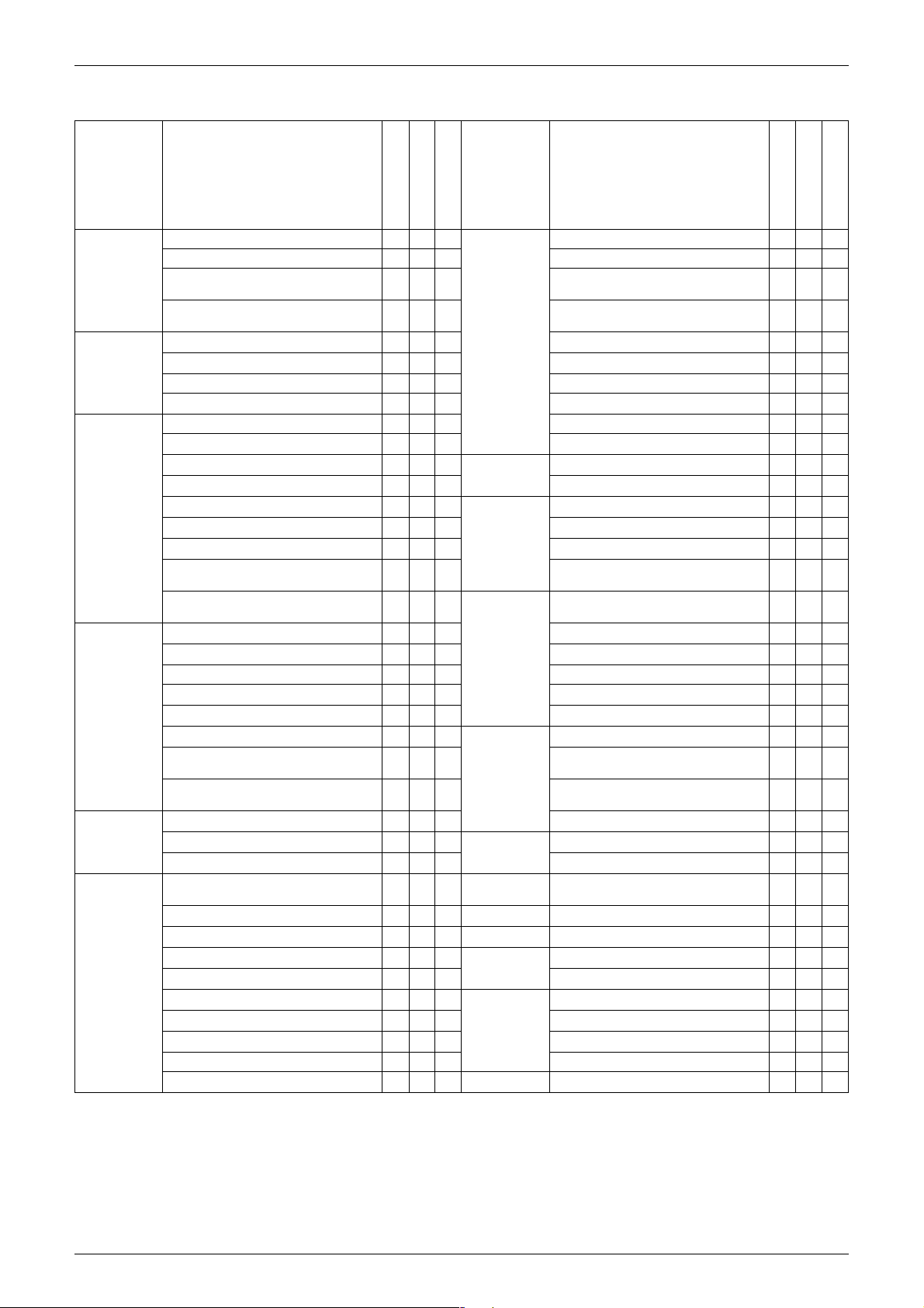
1. List of Functions
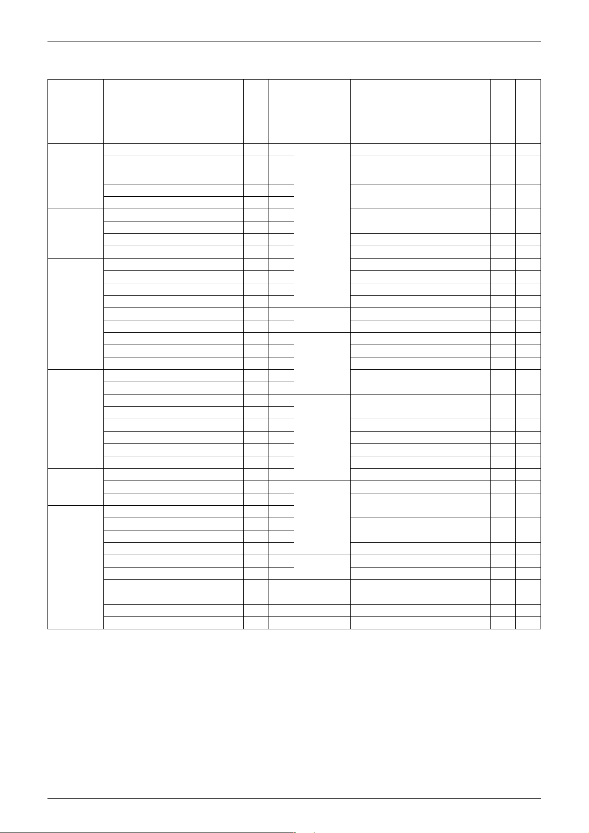
1.1 Cooling Only
Category Functions
FTKS25/35DVM
Basic
Function
Compressor Oval Scroll Compressor — —
Comfortable
Airflow
Comfort
Control
Operation Automatic Operation — — Power Selection — —
Lifestyle
Convenience
Inverter (with Inverter Power Control)
Operation Limit for Cooling (°CDB)
Operation Limit for Heating (°CWB) — — Photocatalytic Deodorizing Filter — —
PAM Control — —
Swing Compressor — —
Rotary Compressor — —
Reluctance DC Motor — — Mold Proof Air Filter
Power-Airflow Flap — — Wipe-clean Flat Panel
Power-Airflow Dual Flaps
Power-Airflow Diffuser — — Mold Proof Operation
Wide-Angle Louvers
Vertical Auto-Swing (Up and Down)
Horizontal Auto-Swing (Right and Left) —
3-D Airflow —
Comfort Airflow Mode — — Worry Free
3-Step Airflow (H/P Only) — — Self-Diagnosis (Digital, LED) Display
Auto Fan Speed
Indoor Unit Quiet Operation
Night Quiet Mode (Automatic) — —
Outdoor Unit Quiet Operation (Manual) — —
Intelligent Eye
Quick Warming Function — — High Ceiling Application — —
Hot-Start Function — — Chargeless — —
Automatic Defrosting — — Either Side Drain (Right or Left)
Programme Dry Function
Fan Only
New Powerful Operation (Non-Inverter) — —
Inverter Powerful Operation
Priority-Room Setting — —
Cooling / Heating Mode Lock — — DIII-NET Compatible (Adaptor) (Option)
Home Leave Operation —
ECONO Mode
Indoor Unit On/Off Switch
Signal Reception Indicator
Temperature Display — —
Another Room Operation — —
Note:
: Holding Functions
{
{{
——
{{
{{
{{
{{
{{
{{
{{
{{
{{
{
{{
{{
Category Functions
FTKS50-71BVMB
Health &
Clean
Timer 24-Hour On/Off Timer
{
{
“Reliability &
Durability”
Flexibility Multi-Split / Split Type Compatible
Remote
Control
Remote
{
Controller
—Wired ——
Air Purifying Filter — —
Air Purifying Filter with Photocatalytic
Deodorizing Function
Titanium Apatite Photocatalytic
Air-Purifying Filter
Washable Grille — —
Heating Dry Operation — —
Good-Sleep Cooling Operation — —
Night Set Mode
Auto-Restart (after Power Failure)
Wiring Error Check — —
Anticorrosion Treatment of Outdoor
Heat Exchanger
Indoor Unit
Flexible Voltage Correspondence
5-Rooms Centralized Controller (Option)
Remote Control Adaptor
(Normal Open-Pulse Contact) (Option)
Remote Control Adaptor
(Normal Open Contact) (Option)
Wireless
FTKS25/35DVM
—
{
{{
{{
{
{{
{{
{{
{{
——
{{
{{
{{
{{
{{
{{
{{
{{
— : No Functions
FTKS50-71BVMB
{
—
—
2 List of Functions
Si12-619A List of Functions
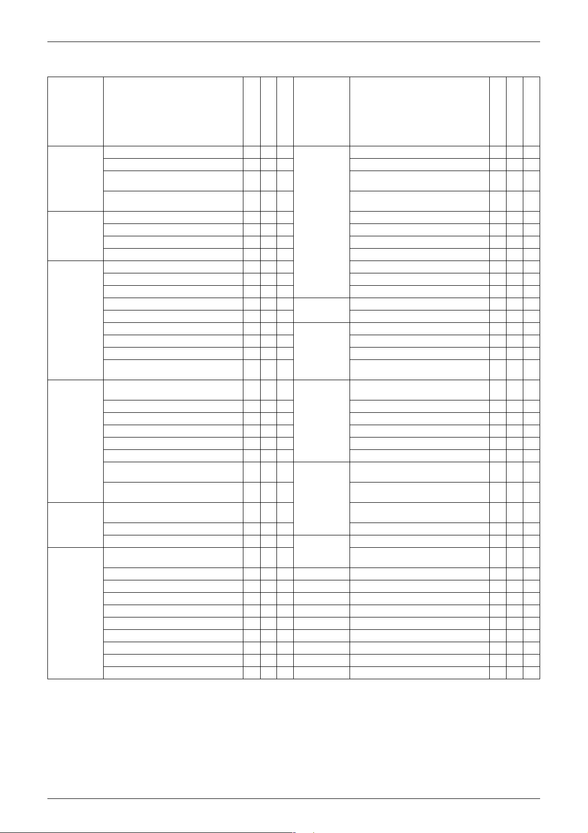
Category Functions
Basic
Function
Inverter (with Inverter Power Control)
Operation Limit for Cooling (°CDB) — — — Photocatalytic Deodorizing Filter — — —
Operation Limit for Heating (°CWB) — — —
PAM Control — — —
Compressor
Oval Scroll Compressor — — — Mold Proof Air Filter
Swing Compressor — — — Wipe-clean Flat Panel
Rotary Compressor — — — Washable Grille — — —
Reluctance DC Motor — — — Mold Proof Operation
Comfortable
Airflow
Power-Airflow Flap — — — Heating Dry Operation — — —
Power-Airflow Dual Flaps
Power-Airflow Diffuser — — —
Wide-Angle Louvers
Vertical Auto-Swing (Up and Down)
Horizontal Auto-Swing (Right and Left)
3-D Airflow
Comfort Airflow Mode — — —
3-Step Airflow (H/P Only) — — —
Comfort
Control
Auto Fan Speed
Indoor Unit Quiet Operation
Night Quiet Mode (Automatic) — — — Chargeless — — —
Outdoor Unit Quiet Operation (Manual) — — — Either Side Drain (Right or Left)
Intelligent Eye
Quick Warming Function — — —
Hot-Start Function — — —
Automatic Defrosting — — —
Operation
Automatic Operation — — — Dlll-NET Compatible (Adaptor) (Option)
Programme Dry Function
Fan Only
Lifestyle
Convenience
New Powerful Operation
(Non-Inverter)
Inverter Powerful Operation
Priority-Room Setting — — —
Cooling / Heating Mode Lock — — —
Home Leave Operation
ECONO Mode
Indoor Unit On/Off Switch
Signal Reception Indicator
Temperature Display — — —
Another Room Operation — — —
Note:
: Holding Functions
{
— : No Functions
FTKS20DVMA
FTKS25/35EVMA
FTKS50-71FVM
FTKS50-71FVMA
{{{
{
{
{
{
—
—
{
{
{
{
{
{
{
{
{
{
{
{
{
{
{
{
{
{
{
{
{
{
{
{
———
{
{
—
{
{
{
{
—
{
{
{
{
—
{
{
Category Functions
Health &
Air Purifying Filter — — —
Clean
Air Purifying Filter with Photocatalytic
Deodorizing Function
Titanium Apatite Photocatalytic
Air-Purifying Filter
Good-Sleep Cooling Operation — — —
Timer
24-Hour On/Off Timer
Night Set Mode
Worry Free
“Reliability &
Durability”
Auto-Restart (after Power Failure)
Self-Diagnosis (Digital, LED) Display
Wiring-Error Check — — —
Anticorrosion Treatment of Outdoor
Heat Exchanger
Flexibility Multi-Split / Split Type Compatible
Indoor Unit
Flexible Voltage Correspondence
High Ceiling Application — — —
Power-Selection — — —
Remote
Control
Remote
Controller
5-Rooms Centralized Controller (Option)
Remote Control Adaptor
(Normal Open-Pulse Contact) (Option)
Remote Control Adaptor
(Normal Open Contact) (Option)
Wireless
Wired ———
FTKS20DVMA
FTKS25/35EVMA
FTKS50-71FVM
FTKS50-71FVMA
———
{{{
{{{
{{{
—
{
{
{
{
{
—
{
{
{
{
{
{
{
{
———
{
{
{
{
{
{
{
{
{
{
{
{
{
{
{
{
{
{
{
{
{
{
{
{
List of Functions 3
List of Functions Si12-619A
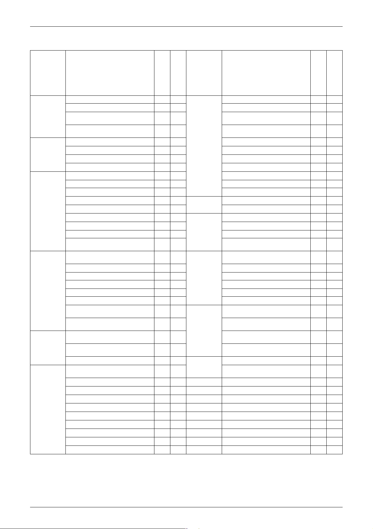
Category Functions
Basic
Function
Compressor
Comfortable
Airflow
Comfort
Control
Operation
Lifestyle
Convenience
Inverter (with Inverter Power Control)
Operation Limit for Cooling (°CDB) — — — Photocatalytic Deodorizing Filter — — —
Operation Limit for Heating (°CWB) — — —
PAM Control — — —
Oval Scroll Compressor — — — Mold Proof Air Filter
Swing Compressor — — — Wipe-clean Flat Panel
Rotary Compressor — — — Washable Grille — — —
Reluctance DC Motor — — — Mold Proof Operation
Power-Airflow Flap — — — Heating Dry Operation — — —
Power-Airflow Dual Flaps
Power-Airflow Diffuser — — —
Wide-Angle Louvers
Vertical Auto-Swing (Up and Down)
Horizontal Auto-Swing (Right and Left)
3-D Airflow
Comfort Airflow Mode — — —
3-Step Airflow (H/P Only) — — —
Auto Fan Speed
Indoor Unit Quiet Operation
Night Quiet Mode (Automatic) — — — Chargeless — — —
Outdoor Unit Quiet Operation (Manual) — — — Either Side Drain (Right or Left)
Intelligent Eye
Quick Warming Function — — —
Hot-Start Function — — —
Automatic Defrosting — — —
Automatic Operation — — — Dlll-NET Compatible (Adaptor) (Option)
Programme Dry Function
Fan Only
New Powerful Operation
(Non-Inverter)
Inverter Powerful Operation
Priority-Room Setting — — —
Cooling / Heating Mode Lock — — —
Home Leave Operation
ECONO Mode
Indoor Unit On/Off Switch
Signal Reception Indicator
Temperature Display — — —
Another Room Operation — — —
: Holding Functions
{
Note:
— : No Functions
FTKS20-35DVMT
FTKS50-71DVMT
FTKS50-71FVLT
{{{
{{{
{{{
{{{
—
{{
{{
—
{{{
{{{
{{{
{{{
{{{
———
{{{
—
{{
——
{
{{{
{{{
Category Functions
Health &
Clean
Timer
Worry Free
“Reliability &
Durability”
Flexibility Multi-Split / Split Type Compatible
Remote
Control
Remote
Controller
Air Purifying Filter — — —
Air Purifying Filter with Photocatalytic
Deodorizing Function
Titanium Apatite Photocatalytic
Air-Purifying Filter
Good-Sleep Cooling Operation — — —
24-Hour On/Off Timer
Night Set Mode
Auto-Restart (after Power Failure)
Self-Diagnosis (Digital, LED) Display
Wiring-Error Check — — —
Anticorrosion Treatment of Outdoor
Heat Exchanger
Indoor Unit
Flexible Voltage Correspondence
High Ceiling Application — — —
Power-Selection — — —
5-Rooms Centralized Controller (Option)
Remote Control Adaptor
(Normal Open-Pulse Contact) (Option)
Remote Control Adaptor
(Normal Open Contact) (Option)
Wireless
Wired ———
FTKS20-35DVMT
FTKS50-71DVMT
FTKS50-71FVLT
—
{
—
—
{
{{{
{{{
{
{{{
{{{
{{{
{{{
———
{{{
{{
{{{
{{{
{{{
{{{
{{{
{{{
{
——
—
4 List of Functions

Si12-619A List of Functions
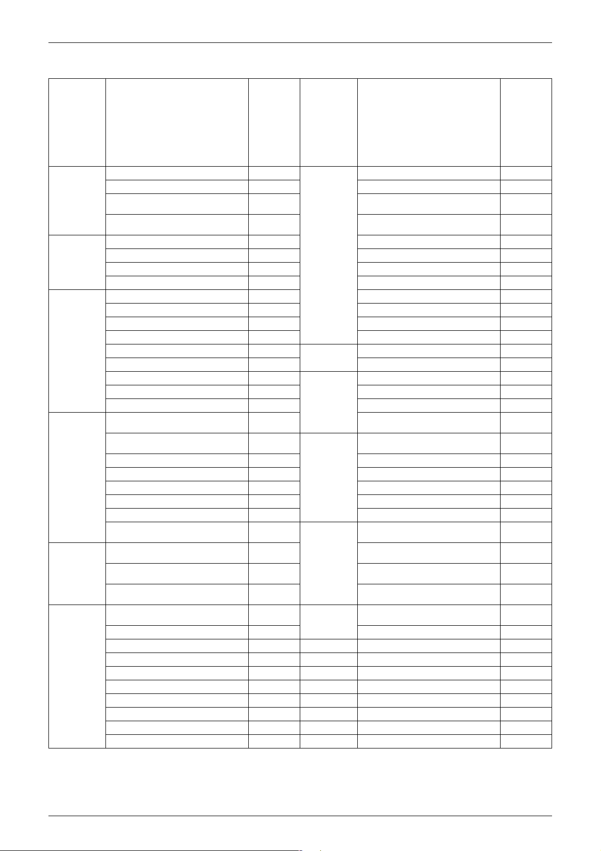
Category Functions
FDKS25/35CAVMB
Basic
Function
Compressor Oval Scroll Compressor — —
Comfortable
Airflow
Comfort
Control
Operation Automatic Operation — — Remote
Lifestyle
Convenience
Inverter (with Inverter Power Control) {{Health &
Operation Limit for Cooling (°CDB) — — Photocatalytic Deodorizing Filter — —
Operation Limit for Heating (°CWB) — —
PAM Control — —
Swing Compressor — —
Rotary Compressor — — Mold Proof Air Filter
Reluctance DC Motor — — Wipe-clean Flat Panel — —
Power-Airflow Flap — — Washable Grille — —
Power-Airflow Dual Flaps — — Mold Proof Operation — —
Power-Airflow Diffuser — — Heating Dry Operation — —
Wide-Angle Louvers — — Good-Sleep Cooling Operation — —
Vertical Auto-Swing (Up and Down) — — Timer 24-Hour On/Off Timer
Horizontal Auto-Swing (Right and Left) — — Night Set Mode
3-D Airflow — — Worry Free
Comfort Airflow Mode — — Self-Diagnosis (Digital, LED) Display
3-Step Airflow (H/P Only) — — Wiring-Error Check — —
Auto Fan Speed
Indoor Unit Quiet Operation
Night Quiet Mode (Automatic) — —
Outdoor Unit Quiet Operation (Manual) — — Flexible Voltage Correspondence
Intelligent Eye — — High Ceiling Application — —
Quick Warming Function — — Chargeless — —
Hot-Start Function — — Either Side Drain (Right or Left) — —
Automatic Defrosting — — Power-Selection — —
Programme Dry Function
Fan Only
New Powerful Operation
(Non-Inverter)
Inverter Powerful Operation
Priority-Room Setting — — Wired — —
Cooling / Heating Mode Lock — —
Home Leave Operation
ECONO Mode — —
Indoor Unit On/Off Switch
Signal Reception Indicator
Temperature Display — —
Another Room Operation — —
Note:
: Holding Functions
{
{{
{{
{{
{{
— — Dlll-NET Compatible (Adaptor) (Option)
{{
{{
{{
{{
Category Functions
FDKS50/60CVMB
Clean
“Reliability &
Durability”
Flexibility Multi-Split / Split Type Compatible
Control
Remote
Controller
— : No Functions
FDKS25/35CAVMB
Air Purifying Filter — —
Air Purifying Filter with Photocatalytic
Deodorizing Function
Titanium Apatite Photocatalytic
Air-Purifying Filter
Auto-Restart (after Power Failure)
Anticorrosion Treatment of Outdoor
Heat Exchanger
Indoor Unit
5-Rooms Centralized Controller (Option)
Remote Control Adaptor
(Normal Open-Pulse Contact) (Option)
Remote Control Adaptor
(Normal Open Contact) (Option)
Wireless
——
——
{{
{{
{{
{{
{{
——
{{
{{
{{
{{
{{
{{
{{
FDKS50/60CVMB
List of Functions 5
List of Functions Si12-619A
Category Functions
FDKS25/35EAVMB
CDKS25-60CVMA
Basic
Function
Compressor Oval Scroll Compressor — — Longlife Filter — —
Comfortable
Airflow
Comfort
Control
Operation
Lifestyle
Convenience
Inverter (with Inverter Power Control)
Operation Limit for Cooling (°CDB) — — Photocatalytic Deodorizing Filter — —
Operation Limit for Heating (°CWB) — —
PAM Control — —
Swing Compressor — — Mold Proof Air Filter
Rotary Compressor — — Wipe-clean Flat Panel — —
Reluctance DC Motor — — Washable Grille — —
Power-Airflow Flap — — Mold Proof Operation — —
Power-Airflow Dual Flaps — — Heating Dry Operation — —
Power-Airflow Diffuser — — Good-Sleep Cooling Operation — —
Wide-Angle Louvers — — Timer 24-Hour On/Off Timer
Vertical Auto-Swing (Up and Down) — — Night Set Mode
Horizontal Auto-Swing (Right and Left) — — Worry Free
3-D Airflow — — Self-Diagnosis (Digital, LED) Display
Comfort Airflow Mode — — Wiring-Error Check — —
3-Step Airflow (H/P Only) — —
Auto Fan Speed
Indoor Unit Quiet Operation
Night Quiet Mode (Automatic) — — High Ceiling Application — —
Outdoor Unit Quiet Operation (Manual) — — Chargeless — —
Intelligent Eye — — Either Side Drain (Right or Left) — —
Quick Warming Function — — Power-Selection — —
Hot-Start Function — —
Automatic Defrosting — —
Automatic Operation — —
Programme Dry Function
Fan Only
New Powerful Operation
(Non-Inverter)
Inverter Powerful Operation
Priority-Room Setting — —
Cooling / Heating Mode Lock — —
Home Leave Operation
ECONO Mode — —
Indoor Unit On/Off Switch
Signal Reception Indicator
Temperature Display — —
Another Room Operation — —
Note:
: Holding Functions
{
{{
{{
{{
{{
{{
—— Wired ——
{{
{{
{{
{{
Category Functions
CDKS25-60DVMT
CDKS25/35EAVMA(T)
Health &
Clean
“Reliability &
Durability”
Flexibility Multi-Split / Split Type Compatible
Remote
Control
Remote
Controller
Air Purifying Filter — —
Air Purifying Filter with Photocatalytic
Deodorizing Function
Titanium Apatite Photocatalytic
Air-Purifying Filter
Auto-Restart (after Power Failure)
Anticorrosion Treatment of Outdoor
Heat Exchanger
Indoor Unit
Flexible Voltage Correspondence
5-Rooms Centralized Controller
(Option)
Remote Control Adaptor
(Normal Open-Pulse Contact) (Option)
Remote Control Adaptor
(Normal Open Contact) (Option)
Dlll-NET Compatible (Adaptor) (Option)
Wireless
FDKS25/35EAVMB
CDKS25-60CVMA
——
——
{{
{{
{{
{{
{{
——
—
{
{{
{{
{{
{{
{{
{{
— : No Functions
CDKS25-60DVMT
CDKS25/35EAVMA(T)
6 List of Functions
Si12-619A List of Functions
Category Functions
Basic
Function
Compressor
Comfortable
Airflow
Comfort
Control
Operation
Lifestyle
Convenience
Inverter (with Inverter Power Control)
Operation Limit for Cooling (°CDB) —
Operation Limit for Heating (°CWB) —
PAM Control —
Oval Scroll Compressor —
Swing Compressor —
Rotary Compressor —
Reluctance DC Motor —
Power-Airflow Flap — — Filter Cleaning Indicator
Power-Airflow Dual Flaps — — Mold Proof Operation — —
Power-Airflow Diffuser — — Heating Dry Operation — —
Wide-Angle Louvers — — Good-Sleep Cooling Operation — —
Vertical Auto-Swing (Up and Down)
Horizontal Auto-Swing (Right and Left) — — Night Set Mode
3-D Airflow — —
Comfort Airflow Mode — — Self-Diagnosis (Digital, LED) Display
3-Step Airflow (H/P Only) — — Wiring-Error Check —
Auto Fan Speed — —
Indoor Unit Quiet Operation — —
Night Quiet Mode (Automatic) —
Outdoor Unit Quiet Operation (Manual) —
Intelligent Eye — — Chargeless —
Quick Warming Function — — Either Side Drain (Right or Left) — —
Hot-Start Function — — Power-Selection — —
Automatic Defrosting — —
Automatic Operation — —
Programme Dry Function
Fan Only
New Powerful Operation
(Non-Inverter)
Inverter Powerful Operation — — Wired
Priority-Room Setting —
Cooling / Heating Mode Lock — —
Home Leave Operation — —
ECONO Mode — —
Indoor Unit On/Off Switch — —
Signal Reception Indicator — —
Temperature Display — —
Another Room Operation — —
Note:
: Holding Functions
{
— : No Functions
FFQ25-60B8V1B
3MKS58EVMA
3MKS75EVMA
4MKS90EVMA
{{
10
~
46
—
{
—
{
—
{
—
{
{
{
—
{
—
{
——
{
Category Functions
Health &
Clean
Timer
Worry Free
“Reliability &
Durability”
Flexibility Multi-Split / Split Type Compatible
Remote
Control
Remote
Controller
Air Purifying Filter — —
Photocatalytic Deodorizing Filter — —
Air Purifying Filter with Photocatalytic
Deodorizing Function
Titanium Apatite Photocatalytic
Air-Purifying Filter
Longlife Filter (Option)
Mold Proof Air Filter
Wipe-clean Flat Panel — —
Washable Grille — —
24-Hour On/Off Timer
Auto-Restart (after Power Failure)
Anticorrosion Treatment of Outdoor
Heat Exchanger
Indoor Unit
Flexible Voltage Correspondence —
High Ceiling Application —
5-Rooms Centralized Controller
(Option)
Remote Control Adaptor
(Normal Open-Pulse Contact) (Option)
Remote Control Adaptor
(Normal Open Contact) (Option)
Dlll-NET Compatible (Adaptor)
(Option)
Wireless
: 72-Hour On/Off Timer
★
FFQ25-60B8V1B
3MKS58EVMA
3MKS75EVMA
4MKS90EVMA
——
——
—
{
—
{
—
{
{
—
★
—
—
—
{
{{
{
—
{
—
{
{
—
{
——
——
——
—
{
—
{
—
{
List of Functions 7
List of Functions Si12-619A
Category Functions
3MKS90EVLT
4MKS100EVLT
Basic
Function
Compressor Oval Scroll Compressor — —
Comfortable
Airflow
Comfort
Control
Operation Automatic Operation — — Power-Selection —
Lifestyle
Convenience
Inverter (with Inverter Power Control)
Operation Limit for Cooling (°CDB)
Operation Limit for Heating (°CWB) — —
PAM Control
Swing Compressor
Rotary Compressor — — Mold Proof Air Filter — —
Reluctance DC Motor
Power-Airflow Flap — — Washable Grille — —
Power-Airflow Dual Flaps — — Mold Proof Operation — —
Power-Airflow Diffuser — — Heating Dry Operation — —
Wide-Angle Louvers — — Good-Sleep Cooling Operation — —
Vertical Auto-Swing (Up and Down) — — Timer 24-Hour On/Off Timer — —
Horizontal Auto-Swing (Right and Left) — — Night Set Mode — —
3-D Airflow — — Worry Free
Comfort Airflow Mode — — Self-Diagnosis (Digital, LED) Display
3-Step Airflow (H/P Only) — — Wiring-Error Check
Auto Fan Speed — —
Indoor Unit Quiet Operation — —
Night Quiet Mode (Automatic)
Outdoor Unit Quiet Operation (Manual)
Intelligent Eye — — Flexible Voltage Correspondence —
Quick Warming Function — — High Ceiling Application — —
Hot-Start Function — — Chargeless
Automatic Defrosting — — Either Side Drain (Right or Left) — —
Programme Dry Function — — Remote
Fan Only — —
New Powerful Operation (Non-Inverter) — —
Inverter Powerful Operation — —
Priority-Room Setting
Cooling / Heating Mode Lock — — Dlll-NET Compatible (Adaptor) (Option) — —
Home Leave Operation — — Remote
ECONO Mode — — Wired — —
Indoor Unit On/Off Switch — —
Signal Reception Indicator — —
Temperature Display — —
Another Room Operation — —
Note:
: Holding Functions
{
{{
–10
10
~
46
{{
{{
{{
{{
{{
{{
Category Functions
3MKS50DVM
4MKS71DVM
Health &
Clean
~
46
“Reliability &
Durability”
Flexibility
Control
Controller
Air Purifying Filter with Bacteriostatic &
Virustatic Functions
Photocatalytic Deodorizing Filter — —
Air Purifying Filter with Photocatalytic
Deodorizing Function
Titanium Apatite Photocatalytic
Air-Purifying Filter
Wipe-clean Flat Panel — —
Auto-Restart (after Power Failure) — —
Anticorrosion Treatment of Outdoor
Heat Exchanger
Multi-Split / Split Type Compatible
Indoor Unit
5-Rooms Centralized Controller (Option) — —
Remote Control Adaptor
(Normal Open-Pulse Contact) (Option)
Remote Control Adaptor
(Normal Open Contact) (Option)
Wireless — —
——
——
——
{{
{{
{{
——
{{
——
——
— : No Functions
3MKS90EVLT
4MKS100EVLT
3MKS50DVM
4MKS71DVM
{
{
8 List of Functions
Si12-619A List of Functions
Category Functions
3MKS50/71ESG
Basic
Function
Compressor Oval Scroll Compressor — —
Comfortable
Airflow
Comfort
Control
Operation Automatic Operation — — Power-Selection
Lifestyle
Convenience
Inverter (with Inverter Power Control)
Operation Limit for Cooling (°CDB)
Operation Limit for Heating (°CWB) — —
PAM Control
Swing Compressor
Rotary Compressor — — Mold Proof Air Filter — —
Reluctance DC Motor
Power-Airflow Flap — — Washable Grille — —
Power-Airflow Dual Flaps — — Mold Proof Operation — —
Power-Airflow Diffuser — — Heating Dry Operation — —
Wide-Angle Louvers — — Good-Sleep Cooling Operation — —
Vertical Auto-Swing (Up and Down) — — Timer 24-Hour On/Off Timer — —
Horizontal Auto-Swing (Right and Left) — — Night Set Mode — —
3-D Airflow — — Worry Free
Comfort Airflow Mode — — Self-Diagnosis (Digital, LED) Display
3-Step Airflow (H/P Only) — — Wiring-Error Check
Auto Fan Speed — —
Indoor Unit Quiet Operation — —
Night Quiet Mode (Automatic)
Outdoor Unit Quiet Operation (Manual)
Intelligent Eye — — Flexible Voltage Correspondence — —
Quick Warming Function — — High Ceiling Application — —
Hot-Start Function — — Chargeless
Automatic Defrosting — — Either Side Drain (Right or Left) — —
Programme Dry Function — — Remote
Fan Only — —
New Powerful Operation (Non-Inverter) — —
Inverter Powerful Operation — —
Priority-Room Setting
Cooling / Heating Mode Lock — — Dlll-NET Compatible (Adaptor) (Option) — —
Home Leave Operation — — Remote
ECONO Mode — — Wired — —
Indoor Unit On/Off Switch — —
Signal Reception Indicator — —
Temperature Display — —
Another Room Operation — —
Note:
: Holding Functions
{
{{
–10
~
46
{{
{{
{{
{{
{{
{{
Category Functions
4MKS80ESG
Health &
Clean
10
~
46
“Reliability &
Durability”
Flexibility
Control
Controller
Air Purifying Filter — —
Photocatalytic Deodorizing Filter — —
Air Purifying Filter with Photocatalytic
Deodorizing Function
Titanium Apatite Photocatalytic
Air-Purifying Filter
Wipe-clean Flat Panel — —
Auto-Restart (after Power Failure) — —
Anticorrosion Treatment of Outdoor
Heat Exchanger
Multi-Split / Split Type Compatible
Indoor Unit
5-Rooms Centralized Controller (Option) — —
Remote Control Adaptor
(Normal Open-Pulse Contact) (Option)
Remote Control Adaptor
(Normal Open Contact) (Option)
Wireless — —
— : No Functions
3MKS50/71ESG
4MKS80ESG
——
——
{{
{{
{{
——
{{
{{
——
——
List of Functions 9

List of Functions Si12-619A
1.2 Heat Pump
Category Functions
Basic
Function
Compressor
Comfortable
Airflow
Comfort
Control
Operation
Lifestyle
Convenience
Inverter (with Inverter Power Control)
Operation Limit for Cooling (°CDB)
Operation Limit for Heating (°CWB)
PAM Control
Oval Scroll Compressor
Swing Compressor
Rotary Compressor
Reluctance DC Motor
Power-Airflow Flap
Power-Airflow Dual Flaps
Power-Airflow Diffuser
Wide-Angle Louvers
Vertical Auto-Swing (Up and Down)
Horizontal Auto-Swing (Right and Left)
3-D Airflow
Comfort Airflow Mode
3-Step Airflow (H/P Only)
Auto Fan Speed
Indoor Unit Quiet Operation
Night Quiet Mode (Automatic)
Outdoor Unit Quiet Operation (Manual)
Intelligent Eye
Quick Warming Function
Hot-Start Function
Automatic Defrosting
Automatic Operation
Programme Dry Function
Fan Only
New Powerful Operation
(Non-Inverter)
Inverter Powerful Operation
Priority-Room Setting
Cooling / Heating Mode Lock
Home Leave Operation
ECONO Mode
Indoor Unit On/Off Switch
Signal Reception Indicator
Temperature Display
Another Room Operation
Note:
: Holding Functions
{
— : No Functions
FTXS20DVMA
FTXS25/35EVMA
FTXS50-71FVMA
{{
——
——
——
——
——
——
——
——
{{
——
{{
{{
{
—
—
{
——
——
{{
{{
——
——
{{
——
{{
——
{{
{{
{{
——
{{
——
——
— {
—
{
{{
{{
——
——
Category Functions
Health &
Clean
Timer
Worry Free
“Reliability &
Durability”
Flexibility Multi-Split / Split Type Compatible
Remote
Control
Remote
Controller
Air Purifying Filter
Photocatalytic Deodorizing Filter
Air Purifying Filter with Photocatalytic
Deodorizing Function
Titanium Apatite Photocatalytic
Air-Purifying Filter
Longlife Filter (Option)
Mold Proof Air Filter
Wipe-clean Flat Panel
Washable Grille
Filter Cleaning Indicator
Mold Proof Operation
Heating Dry Operation
Good-Sleep Cooling Operation
24-Hour On/Off Timer
Night Set Mode
Auto-Restart (after Power Failure)
Self-Diagnosis (Digital, LED) Display
Wiring-Error Check
Anticorrosion Treatment of Outdoor
Heat Exchanger
Indoor Unit
Flexible Voltage Correspondence
High Ceiling Application
Chargeless
Either Side Drain (Right or left)
Power-Selection
5-Rooms Centralized Controller
(Option)
Remote Control Adaptor
(Normal Open-Pulse Contact) (Option)
Remote Control Adaptor
(Normal Open Contact) (Option)
Dlll-NET Compatible (Adaptor)
(Option)
Wireless
Wired
FTXS20DVMA
FTXS25/35EVMA
FTXS50-71FVMA
——
——
——
{{
——
{{
{{
——
——
—
{
——
——
{{
{{
{{
{{
——
——
{{
{{
——
——
{{
——
{{
{{
{{
{{
{{
——
10 List of Functions
Si12-619A List of Functions
Category Functions
FTXS20-35DVMT
FTXS50-71DVMT
Basic
Function
Compressor Oval Scroll Compressor — — — Longlife Filter — — —
Comfortable
Airflow
Comfort
Control
Operation
Lifestyle
Convenience
Inverter (with Inverter Power Control)
Operation Limit for Cooling (°CDB) — — — Photocatalytic Deodorizing Filter — — —
Operation Limit for Heating (°CWB) — — —
PAM Control — — —
Swing Compressor — — — Mold Proof Air Filter
Rotary Compressor — — — Wipe-clean Flat Panel
Reluctance DC Motor — — — Washable Grille — — —
Power-Airflow Flap — — — Mold Proof Operation
Power-Airflow Dual Flaps
Power-Airflow Diffuser — — — Good-Sleep Cooling Operation — — —
Wide-Angle Louvers
Vertical Auto-Swing (Up and Down)
Horizontal Auto-Swing (Right and Left) —
3-D Airflow —
Comfort Airflow Mode — — — Wiring-Error Check — — —
3-Step Airflow (H/P Only) — — —
Auto Fan Speed
Indoor Unit Quiet Operation
Night Quiet Mode (Automatic) — — — High Ceiling Application — — —
Outdoor Unit Quiet Operation (Manual) — — — Chargeless — — —
Intelligent Eye
Quick Warming Function ——— Power-Selection ———
Hot-Start Function
Automatic Defrosting — — —
Automatic Operation
Programme Dry Function
Fan Only
New Powerful Operation
(Non-Inverter)
Inverter Powerful Operation
Priority-Room Setting — — —
Cooling / Heating Mode Lock — — —
Home Leave Operation —
ECONO Mode
Indoor Unit On/Off Switch
Signal Reception Indicator
Temperature Display — — —
Another Room Operation — — —
Note:
: Holding Functions
{
{{{
{{{
{{{
{{{
{{
{{
{{{
{{{
{{{
{{{
{{{
{{{
{{{
——— Wired ———
{{{
{{
——
{
{{{
{{{
Category Functions
FTXS50-71FVLT
Health &
Clean
Timer 24-Hour On/Off Timer
Worry Free
“Reliability &
Durability”
Flexibility Multi-Split / Split Type Compatible
Remote
Control
Remote
Controller
Air Purifying Filter — — —
Air Purifying Filter with Photocatalytic
Deodorizing Function
Titanium Apatite Photocatalytic
Air-Purifying Filter
Heating Dry Operation — — —
Night Set Mode
Auto-Restart (after Power Failure)
Self-Diagnosis (Digital, LED) Display
Anticorrosion Treatment of Outdoor
Heat Exchanger
Indoor Unit
Flexible Voltage Correspondence
Either Side Drain (Right or Left)
5-Rooms Centralized Controller
(Option)
Remote Control Adaptor
(Normal Open-Pulse Contact) (Option)
Remote Control Adaptor
(Normal Open Contact) (Option)
Dlll-NET Compatible (Adaptor) (Option)
Wireless
FTXS20-35DVMT
FTXS50-71DVMT
—
{
—
—
{
{{{
{{{
{ ——
{{{
{{{
{{{
{{{
———
{{{
{{
{{{
{{{
{{{
{{{
{{{
{{{
{
—
— : No Functions
FTXS50-71FVLT
List of Functions 11
List of Functions Si12-619A
Category Functions
Basic
Function
Compressor Oval Scroll Compressor
Comfortable
Airflow
Comfort
Control
Operation
Lifestyle
Convenience
Inverter (with Inverter Power Control)
Operation Limit for Cooling (°CDB) — —
Operation Limit for Heating (°CWB)
PAM Control — —
Swing Compressor
Rotary Compressor
Reluctance DC Motor
Power-Airflow Flap
Power-Airflow Dual Flaps — — Heating Dry Operation — —
Power-Airflow Diffuser
Wide-Angle Louvers
Vertical Auto-Swing (Up and Down)
Horizontal Auto-Swing (Right and Left)
3-D Airflow
Comfort Airflow Mode — — Wiring-Error Check — —
3-Step Airflow (H/P Only)
Auto Fan Speed
Indoor Unit Quiet Operation
Night Quiet Mode (Automatic) — — High Ceiling Application — —
Outdoor Unit Quiet Operation (Manual)
Intelligent Eye — — Either Side Drain (Right or left) — —
Quick Warming Function
Hot-Start Function
Automatic Defrosting
Automatic Operation
Programme Dry Function
Fan Only
New Powerful Operation
(Non-Inverter)
Inverter Powerful Operation
Priority-Room Setting
Cooling / Heating Mode Lock
Home Leave Operation
ECONO Mode
Indoor Unit On/Off Switch
Signal Reception Indicator
Temperature Display
Another Room Operation
Note:
: Holding Functions
{
— : No Functions
FDXS25-60CVMA
CDXS25-60DVMT
{{
——
——
——
——
——
——
——
——
——
——
——
——
{{
{{
——
——
{{
——
{{
{{
{{
——
{{
——
——
{{
——
{{
{{
——
——
Category Functions
Health &
Clean
Timer 24-Hour On/Off Timer
Worry Free
“Reliability &
Durability”
Flexibility Multi-Split / Split Type Compatible
Remote
Control
Remote
Controller
Air Purifying Filter — —
Photocatalytic Deodorizing Filter
Air Purifying Filter with Photocatalytic
Deodorizing Function
Titanium Apatite Photocatalytic
Air-Purifying Filter
Longlife Filter (Option)
Mold Proof Air Filter
Wipe-clean Flat Panel
Washable Grille
Mold Proof Operation
Good-Sleep Cooling Operation
Night Set Mode
Auto-Restart (after Power Failure)
Self-Diagnosis (Digital, LED) Display
Anticorrosion Treatment of Outdoor
Heat Exchanger
Indoor Unit
Flexible Voltage Correspondence
Chargeless
Power-Selection
5-Rooms Centralized Controller
(Option)
Remote Control Adaptor
(Normal Open-Pulse Contact) (Option)
Remote Control Adaptor
(Normal Open Contact) (Option)
Dlll-NET Compatible (Adaptor)
(Option)
Wireless
Wired
FDXS25-60CVMA
CDXS25-60DVMT
—
—
——
—
—
——
{
{
——
—
—
—
—
—
—
{
{
{
{
{
{
{
{
—
—
—
{
{
{
—
—
—
—
{
{
{
{
{
{
{
{
{
{
—
—
12 List of Functions
Si12-619A List of Functions
Category Functions
Basic
Function
Compressor Oval Scroll Compressor
Comfortable
Airflow
Comfort
Control
Operation
Lifestyle
Convenience
Inverter (with Inverter Power Control)
Operation Limit for Cooling (°CDB) —
Operation Limit for Heating (°CWB) —
PAM Control —
Swing Compressor
Rotary Compressor
Reluctance DC Motor
Power-Airflow Flap
Power-Airflow Dual Flaps
Power-Airflow Diffuser
Wide-Angle Louvers
Vertical Auto-Swing (Up and Down)
Horizontal Auto-Swing (Right and Left)
3-D Airflow
Comfort Airflow Mode
3-Step Airflow (H/P Only)
Auto Fan Speed
Indoor Unit Quiet Operation
Night Quiet Mode (Automatic)
Outdoor Unit Quiet Operation (Manual)
Intelligent Eye
Quick Warming Function
Hot-Start Function
Automatic Defrosting
Automatic Operation
Programme Dry Function
Fan Only
New Powerful Operation
(Non-Inverter)
Inverter Powerful Operation
Priority-Room Setting
Cooling / Heating Mode Lock
Home Leave Operation
ECONO Mode
Indoor Unit On/Off Switch
Signal Reception Indicator
Temperature Display
Another Room Operation
Note:
: Holding Functions
{
— : No Functions
{
—
—
—
—
—
—
—
—
—
—
—
—
—
{
{
—
—
—
—
{
—
{
{
{
—
{
—
—
{
—
{
{
—
—
Category Functions
CDXS25/35EAVMA(T)
Health &
Clean
Timer 24-Hour On/Off Timer
Worry Free
“Reliability &
Durability”
Flexibility Multi-Split / Split Type Compatible
Remote
Control
Remote
Controller
Air Purifying Filter
Photocatalytic Deodorizing Filter
Air Purifying Filter with Photocatalytic
Deodorizing Function
Titanium Apatite Photocatalytic
Air-Purifying Filter
Longlife Filter (Option)
Mold Proof Air Filter
Wipe-clean Flat Panel
Washable Grille
Filter Cleaning Indicator
Mold Proof Operation
Heating Dry Operation
Good-Sleep Cooling Operation
Night Set Mode
Auto-Restart (after Power Failure)
Self-Diagnosis (Digital, LED) Display
Wiring-Error Check
Anticorrosion Treatment of Outdoor
Heat Exchanger
Indoor Unit
Flexible Voltage Correspondence
High Ceiling Application
Chargeless
Either Side Drain (Right or left)
Power-Selection
5-Rooms Centralized Controller
(Option)
Remote Control Adaptor
(Normal Open-Pulse Contact) (Option)
Remote Control Adaptor
(Normal Open Contact) (Option)
Dlll-NET Compatible (Adaptor)
(Option)
Wireless
Wired
CDXS25/35EAVMA(T)
—
—
—
—
—
{
—
—
—
—
—
—
{
{
{
{
—
—
—
{
—
—
—
—
{
{
{
{
{
—
List of Functions 13
List of Functions Si12-619A
Category Functions
Basic
Function
Compressor Oval Scroll Compressor
Comfortable
Airflow
Comfort
Control
Operation
Lifestyle
Convenience
Inverter (with Inverter Power Control)
Operation Limit for Cooling (°CDB) — — —
Operation Limit for Heating (°CWB) — — —
PAM Control — — —
Swing Compressor
Rotary Compressor — — — Wipe-clean Flat Panel — — —
Reluctance DC Motor
Power-Airflow Flap
Power-Airflow Dual Flaps — — — Mold Proof Operation — — —
Power-Airflow Diffuser — — — Heating Dry Operation — — —
Wide-Angle Louvers
Vertical Auto-Swing (Up and Down)
Horizontal Auto-Swing (Right and Left)
3-D Airflow
Comfort Airflow Mode
3-Step Airflow (H/P Only)
Auto Fan Speed
Indoor Unit Quiet Operation
Night Quiet Mode (Automatic)
Outdoor Unit Quiet Operation (Manual) — — — High Ceiling Application — — —
Intelligent Eye — — — Chargeless — — —
Quick Warming Function
Hot-Start Function
Automatic Defrosting — — —
Automatic Operation
Programme Dry Function
Fan Only
New Powerful Operation
(Non-Inverter)
Inverter Powerful Operation
Priority-Room Setting
Cooling / Heating Mode Lock
Home Leave Operation
ECONO Mode
Indoor Unit On/Off Switch
Signal Reception Indicator
Temperature Display
Another Room Operation
Note:
: Holding Functions
{
— : No Functions
FLXS25-60BVMA
FVXS35/50BVMA
FFQ25-60B8V1B
{{{
———
———
———
{{
—
— { —
{{{
———
———
———
—
{{
{{
———
———
{{{
{{{
{{{
{{{
———
{{
———
———
{{
———
{{
{{
———
———
—
{
—
—
—
—
—
—
Category Functions
Health &
Clean
Timer
Worry Free
“Reliability &
Durability”
Flexibility Multi-Split / Split Type Compatible
Remote
Control
Remote
Controller
Air Purifying Filter
Photocatalytic Deodorizing Filter
Air Purifying Filter with Photocatalytic
Deodorizing Function
Titanium Apatite Photocatalytic
Air-Purifying Filter
Longlife Filter (Option)
Mold Proof Air Filter
Washable Grille
Filter Cleaning Indicator
Good-Sleep Cooling Operation
24-Hour On/Off Timer
Night Set Mode
Auto-Restart (after Power Failure)
Self-Diagnosis (Digital, LED) Display
Wiring-Error Check
Anticorrosion Treatment of Outdoor
Heat Exchanger
Indoor Unit
Flexible Voltage Correspondence
Either Side Drain (Right or Left)
Power-Selection
5-Rooms Centralized Controller
(Option)
Remote Control Adaptor
(Normal Open-Pulse Contact) (Option)
Remote Control Adaptor
(Normal Open Contact) (Option)
Dlll-NET Compatible (Adaptor)
(Option)
Wireless
Wired
: 72-Hour On/Off Timer
★
FLXS25-60BVMA
FVXS35/50BVMA
FFQ25-60B8V1B
{{
{{—
———
———
——
{{{
—
——
———
{{
{{
{{{
{{{
———
———
{{{
{{
— {
———
{{
{{
{{
{{{
{{{
——
—
{
—
{
{
{
★
—
—
—
—
—
—
{
14 List of Functions
Si12-619A List of Functions
Category Functions
3MXS52EVMA
3MXS68EVMA
Basic
Function
Compressor Oval Scroll Compressor — — Longlife Filter (Option) — —
Comfortable
Airflow
Comfort
Control
Operation
Lifestyle
Convenience
Inverter (with Inverter Power Control)
Operation Limit for Cooling (°CDB)
Operation Limit for Heating (°CWB)
PAM Control
Swing Compressor
Rotary Compressor — — Wipe-clean Flat Panel — —
Reluctance DC Motor
Power-Airflow Flap — — Filter Cleaning Indicator — —
Power-Airflow Dual Flaps — — Mold Proof Operation — —
Power-Airflow Diffuser — — Heating Dry Operation — —
Wide-Angle Louvers — — Good-Sleep Cooling Operation — —
Vertical Auto-Swing (Up and Down) — — Timer 24-Hour On/Off Timer — —
Horizontal Auto-Swing (Right and Left) — — Night Set Mode — —
3-D Airflow — — Worry Free
Comfort Airflow Mode
3-Step Airflow (H/P Only)
Auto Fan Speed — —
Indoor Unit Quiet Operation — —
Night Quiet Mode (Automatic)
Outdoor Unit Quiet Operation (Manual)
Intelligent Eye — — Chargeless 30m 40m
Quick Warming Function
Hot-Start Function — — Power-Selection — —
Automatic Defrosting
Automatic Operation — —
Programme Dry Function — —
Fan Only — —
New Powerful Operation
(Non-Inverter)
Inverter Powerful Operation — — Wired — —
Priority-Room Setting
Cooling / Heating Mode Lock
Home Leave Operation
ECONO Mode
Indoor Unit On/Off Switch
Signal Reception Indicator
Temperature Display
Another Room Operation
Note:
: Holding Functions
{
{{
–5
–10
~
46
–15
–15
~
15.5
15.5
{{
{{
{{
——
——
{{
{{
{{
{{
——
{{
{{
——
——
——
——
——
——
Category Functions
4MXS80EVMA
Health &
Clean
~
46
~
“Reliability &
Durability”
Flexibility Multi-Split / Split Type Compatible
Remote
Control
Remote
Controller
Air Purifying Filter
Photocatalytic Deodorizing Filter — —
Air Purifying Filter with Photocatalytic
Deodorizing Function
Titanium Apatite Photocatalytic
Air-Purifying Filter
Mould Proof Air Filter
Washable Grille
Auto-Restart (after Power Failure) — —
Self-Diagnosis (Digital, LED) Display
Wiring-Error Check
Anticorrosion Treatment of Outdoor
Heat Exchanger
Indoor Unit
Flexible Voltage Correspondence
High Ceiling Application
Either Side Drain (Right or Left)
5-Rooms Centralized Controller
(Option)
Remote Control Adaptor
(Normal Open-Pulse Contact) (Option)
Remote Control Adaptor
(Normal Open Contact) (Option)
Dlll-NET Compatible (Adaptor)
(Option)
Wireless — —
3MXS52EVMA
3MXS68EVMA
——
——
——
——
——
{{
{{
{{
——
{{
——
——
——
——
——
——
— : No Functions
4MXS80EVMA
List of Functions 15
List of Functions Si12-619A
Category Functions
3MXS90EVLT
4MXS100EVLT
Basic
Function
Compressor Oval Scroll Compressor — Longlife Filter —
Comfortable
Airflow
Comfort
Control
Operation
Lifestyle
Convenience
Inverter (with Inverter Power Control)
Operation Limit for Cooling (°CDB)
Operation Limit for Heating (°CWB)
PAM Control
Swing Compressor
Rotary Compressor — Wipe-clean Flat Panel —
Reluctance DC Motor
Power-Airflow Flap — Mold Proof Operation —
Power-Airflow Dual Flaps — Heating Dry Operation —
Power-Airflow Diffuser — Good-Sleep Cooling Operation —
Wide-Angle Louvers — Timer 24-Hour On/Off Timer —
Vertical Auto-Swing (Up and Down) — Night Set Mode —
Horizontal Auto-Swing (Right and Left) — Worry Free
3-D Airflow — Self-Diagnosis (Digital, LED) Display
Comfort Airflow Mode — Wiring-Error Check
3-Step Airflow (H/P Only) —
Auto Fan Speed —
Indoor Unit Quiet Operation — Flexible Voltage Correspondence —
Night Quiet Mode (Automatic)
Outdoor Unit Quiet Operation (Manual)
Intelligent Eye — Either Side Drain (Right or Left) —
Quick Warming Function
Hot-Start Function —
Automatic Defrosting
Automatic Operation —
Programme Dry Function — Dlll-NET Compatible (Adaptor) (Option) —
Fan Only — Remote
New Powerful Operation
(Non-Inverter)
Inverter Powerful Operation —
Priority-Room Setting
Cooling / Heating Mode Lock
Home Leave Operation —
ECONO Mode —
Indoor Unit On/Off Switch —
Signal Reception Indicator —
Temperature Display —
Another Room Operation —
Note:
: Holding Functions
{
{
–10
~
46
–15
~
15.5
{
{
{
{
{
{
{
—Wired —
{
{
Category Functions
Health &
Clean
“Reliability &
Durability”
Flexibility Multi-Split / Split Type Compatible
Remote
Control
Controller
Air Purifying Filter —
Photocatalytic Deodorizing Filter —
Air Purifying Filter with Photocatalytic
Deodorizing Function
Titanium Apatite Photocatalytic
Air-Purifying Filter
Mold Proof Air Filter —
Washable Grille —
Auto-Restart (after Power Failure) —
Anticorrosion Treatment of Outdoor
Heat Exchanger
Indoor Unit
High Ceiling Application —
Chargeless 40m
Power-Selection —
5-Rooms Centralized Controller
(Option)
Remote Control Adaptor
(Normal Open-Pulse Contact) (Option)
Remote Control Adaptor
(Normal Open Contact) (Option)
Wireless —
—
—
{
{
{
—
—
—
—
— : No Functions
3MXS90EVLT
4MXS100EVLT
16 List of Functions

Si12-619A
Part 2
Specifications
1. Specifications........................................................................................18
1.1 Indoor Units - Cooling Only ....................................................................18
1.2 Outdoor Units - Cooling Only .................................................................32
1.3 Indoor Units - Heat Pump .......................................................................38
1.4 Outdoor Units - Heat Pump ....................................................................48
Specifications 17

Specifications Si12-619A
1. Specifications
1.1 Indoor Units - Cooling Only
Wall Mounted Type
50Hz 230V
Model FTKS25DVM FTKS35DVM
Rated Capacity 2.5kW Class 3.5kW Class
Front Panel Color White White
Air Flow Rates
Fan
Air Direction Control Right, Left, Horizontal, Downward Right, Left, Horizontal, Downward
Air Filter Removable-Washable-Mildew Proof Removable-Washable-Mildew Proof
Running Current (Rated) A 0.16 0.18
Power Consumption (Rated) W 35 40
Power Factor % 95.1 96.6
Temperature Control Microcomputer Control Microcomputer Control
Dimensions (H×W×D) mm 283×800×195 283×800×195
Packaged Dimensions (H×W×D) mm 265×855×340 265×855×340
Weight kg 9 9
Gross Weight kg 12 12
Operation
Sound
Heat Insulation Both Liquid and Gas Pipes Both Liquid and Gas Pipes
Piping Connection
Drawing No. 3D049321 3D049322
Type Cross Flow Fan Cross Flow Fan
Motor Output W 40 40
Speed Steps 5 Steps, Quiet, Auto 5 Steps, Quiet, Auto
H/L/SL dBA 37/25/22 39/26/23
m³/min
(cfm)
Liquid mm
Gas mm
Drain mm
H 8.7 (307) 8.9 (314)
M 6.7 (237) 6.9 (242)
L 4.7 (166) 4.8 (169)
SL 3.9 (138) 4.0 (141)
φ
φ
φ
6.4
9.5
18.0
φ
φ
φ
6.4
9.5
18.0
Model FTKS50BVMB FTKS60BVMB
Rated Capacity 5.0kW Class 6.0kW Class
Front Panel Color White White
Air Flow Rates
Fan
Air Direction Control Right, Left, Horizontal, Downward Right, Left, Horizontal, Downward
Air Filter Removable-Washable-Mildew Proof Removable-Washable-Mildew Proof
Running Current (Rated) A 0.18 0.18
Power Consumption (Rated) W 40 40
Power Factor % 96.6 96.6
Temperature Control Microcomputer Control Microcomputer Control
Dimensions (H×W×D) mm 290×795×238 290×1,050×238
Packaged Dimensions (H×W×D) mm 280×840×338 337×1,147×366
Weight kg 9 12
Gross Weight kg 13 17
Operation
Sound
Sound Power H dBA 63 63
Heat Insulation Both Liquid and Gas Pipes Both Liquid and Gas Pipes
Piping Connection
Drawing No. 3D040781A 3D040782A
Type Cross Flow Fan Cross Flow Fan
Motor Output W 40 43
Speed Steps 5 Steps, Quiet, Auto 5 Steps, Quiet, Auto
H/M/L/SL dBA 44/40/35/32 45/41/36/33
m³/min
(cfm)
Liquid mm
Gas mm
Drain mm
H 11.4 (402) 16.2 (572)
M 9.7 (342) 13.6 (480)
L 8.0 (282) 11.4 (402)
SL 7.1 (251) 10.2 (360)
φ
φ
φ
6.4
12.7
18.0
φ
φ
φ
6.4
12.7
18.0
Conversion Formulae
kcal/h=kW×860
Btu/h=kW×3414
cfm=m³/min×35.3
18 Specifications

Si12-619A Specifications
50Hz 230V
Model FTKS71BVMB
Rated Capacity 7.1kW Class
Front Panel Color Whit e
Air Flow Rates
Fan
Air Direction Control Right, Left, Horizontal, Downward
Air Filter Removable-Washable-Mildew Proof
Running Current (Rated) A 0.20
Power Consumption (Rated) W 45
Power Factor % 96.4
Temperature Control Microcomputer Control
Dimensions (H×W×D) mm 290×1,050×238
Packaged Dimensions (H×W×D) mm 337×1,147×366
Weight kg 12
Gross Weight kg 17
Operation
Sound
Sound Power H dBA 63
Heat Insulation Both Liquid and Gas Pipes
Piping Connection
Drawing No. 3D040783A
Type Cross Flow Fan
Motor Output W 43
Speed Steps 5 Steps, Quiet, Auto
H/M/L/SL dBA 46/42/37/34
m³/min
(cfm)
Liquid mm
Gas mm
Drain mm
H 16.7 (590)
M 14.2 (501)
L 11.6 (409)
SL 10.6 (374)
φ
6.4
15.9
φ
18.0
φ
50Hz 220-230-240V / 60Hz 220-230V
Model FTKS20DVMA FTKS25EVMA
Rated Capacity 2.0kW Class 2.5kW Class
Front Panel Color White White
Air Flow Rates
Fan
Air Direction Control Right, Left, Horizontal, Downward Right, Left, Horizontal, Downward
Air Filter Removable-Washable-Mildew Proof Removable-Washable-Mildew Proof
Running Current (Rated) A 0.17-0.16-0.15/0.17-0.16 0.17-0.16-0.15/0.17-0.16
Power Consumption (Rated) W 35 35
Power Factor % 93.6-95.1-97.2/93.6-95.1 93.6-95.1-97.2/93.6-95.1
Temperature Control Microcomputer Control Microcomputer Control
Dimensions (H×W×D) mm 283×800×195 283×800×195
Packaged Dimensions (H×W×D) mm 265×855×340 265×855×340
Weight kg 9 9
Gross Weight kg 12 12
Operation
Sound
Sound Power H dBA — 61
Heat Insulation Both Liquid and Gas Pipes Both Liquid and Gas Pipes
Piping Connection
Drawing No. 3D049754 3D054408
Type Cross Flow Fan Cross Flow Fan
Motor Output W 40 40
Speed Steps 5 Steps, Quiet, Auto 5 Steps, Quiet, Auto
H/M/L/SL dBA 37/—/25/22 37/31/25/22
m³/min
(cfm)
Liquid mm
Gas mm
Drain mm
H 8.7 (307) 8.7 (307)
M 6.7 (237) 6.7 (237)
L 4.7 (166) 4.7 (166)
SL 3.9 (138) 3.9 (138)
φ
φ
φ
6.4
9.5
18.0
φ
φ
φ
6.4
9.5
18.0
Conversion Formulae
kcal/h=kW×860
Btu/h=kW×3414
cfm=m³/min×35.3
Specifications 19

Specifications Si12-619A
50Hz 220-230-240V / 60Hz 220-230V
Model FTKS35EVMA
Rated Capacity 3.5kW Class
Front Panel Color Whit e
Air Flow Rates
Fan
Air Direction Control Right, Left, Horizontal, Downward
Air Filter Removable-Washable-Mildew Proof
Running Current (Rated) A 0.19-0.18-0.17/0.19-0.18
Power Consumption (Rated) W 40
Power Factor % 95.7-96.6-98.0/95.7-96.6
Temperature Control Microcomputer Control
Dimensions (H×W×D) mm 283×800×195
Packaged Dimensions (H×W×D) mm 265×855×340
Weight kg 9
Gross Weight kg 12
Operation
Sound
Sound Power H dBA 62
Heat Insulation Both Liquid and Gas Pipes
Piping Connection
Drawing No. 3D054409
Type Cross Flow Fan
Motor Output W 40
Speed Steps 5 Steps, Quiet, Auto
H/M/L/SL dBA 38/32/26/23
m³/min
(cfm)
Liquid mm
Gas mm
Drain mm
H 8.9 (314)
M 6.9 (244)
L 4.8 (169)
SL 4.0 (141)
φ
6.4
9.5
φ
18.0
φ
Model FTKS50FVM FTKS60FVM
Rated Capacity 5.0kW Class 6.0kW Class
Front Panel Color White White
Air Flow Rates
Fan
Air Direction Control Right, Left, Horizontal, Downward Right, Left, Horizontal, Downward
Air Filter Removable-Washable-Mildew Proof Removable-Washable-Mildew Proof
Running Current (Rated) A 0.15 0.18
Power Consumption (Rated) W 34 40
Power Factor % 98.6 96.6
Temperature Control Microcomputer Control Microcomputer Control
Dimensions (H×W×D) mm 290×1,050×238 290×1,050×238
Packaged Dimensions (H×W×D) mm 337×1,147×366 337×1,147×366
Weight kg 12 12
Gross Weight kg 17 17
Operation
Sound
Heat Insulation Both Liquid and Gas Pipes Both Liquid and Gas Pipes
Piping Connection
Drawing No. 3D056225 3D056226
Type Cross Flow Fan Cross Flow Fan
Motor Output W 43 43
Speed Steps 5 Steps, Quiet, Auto 5 Steps, Quiet, Auto
H/M/L/SL dBA 43/39/34/31 45/41/36/33
m³/min
(cfm)
Liquid mm
Gas mm
Drain mm
H 14.7 (519) 16.2 (572)
M 12.6 (445) 13.9 (491)
L 10.2 (360) 11.5 (406)
SL 9.2 (325) 10.0 (353)
φ
φ
φ
6.4
12.7
18.0
φ
φ
φ
6.4
12.7
18.0
Conversion Formulae
kcal/h=kW×860
Btu/h=kW×3414
cfm=m³/min×35.3
50Hz 230V
20 Specifications

Si12-619A Specifications
50Hz 230V
Model FTKS71FVM
Rated Capacity 7.1kW Class
Front Panel Color Whit e
Air Flow Rates
Fan
Air Direction Control Right, Left, Horizontal, Downward
Air Filter Removable-Washable-Mildew Proof
Running Current (Rated) A 0.20
Power Consumption (Rated) W 45
Power Factor % 97.8
Temperature Control Microcomputer Control
Dimensions (H×W×D) mm 290×1,050×238
Packaged Dimensions (H×W×D) mm 337×1,147×366
Weight kg 12
Gross Weight kg 17
Operation
Sound
Sound Power H dBA —
Heat Insulation Both Liquid and Gas Pipes
Piping Connection
Drawing No. 3D056227
Type Cross Flow Fan
Motor Output W 43
Speed Steps 5 Steps, Quiet, Auto
H/M/L/SL dBA 46/42/37/34
m³/min
(cfm)
Liquid mm
Gas mm
Drain mm
H 17.4 (614)
M 14.6 (516)
L 11.9 (420)
SL 10.7 (378)
φ
6.4
15.9
φ
18.0
φ
50Hz 220-230-240V / 60Hz 220-230V
Model FTKS50FVMA FTKS60FVMA
Rated Capacity 5.0kW Class 6.0kW Class
Front Panel Color White White
Air Flow Rates
Fan
Air Direction Control Right, Left, Horizontal, Downward Right, Left, Horizontal, Downward
Air Filter Removable-Washable-Mildew Proof Removable-Washable-Mildew Proof
Running Current (Rated) A 0.16-0.15-0.15/0.16-0.15 0.19-0.18-0.17/0.19-0.18
Power Consumption (Rated) W 34 40
Power Factor % 96.6-98.6-94.4/96.6-98.6 95.7-96.6-98.0/95.7-96.6
Temperature Control Microcomputer Control Microcomputer Control
Dimensions (H×W×D) mm 290×1,050×238 290×1,050×238
Packaged Dimensions (H×W×D) mm 337×1,147×366 337×1,147×366
Weight kg 12 12
Gross Weight kg 17 17
Operation
Sound
Sound Power H dBA 60 61
Heat Insulation Both Liquid and Gas Pipes Both Liquid and Gas Pipes
Piping Connection
Drawing No. 3D054876 3D054877
Type Cross Flow Fan Cross Flow Fan
Motor Output W 43 43
Speed Steps 5 Steps, Quiet, Auto 5 Steps, Quiet, Auto
H/M/L/SL dBA 44/40/35/32 45/41/36/33
m³/min
(cfm)
Liquid mm
Gas mm
Drain mm
H 14.7 (519) 16.2 (572)
M 12.6 (445) 13.9 (491)
L 10.2 (360) 11.5 (406)
SL 9.2 (325) 10.0 (353)
φ
φ
φ
6.4
12.7
18.0
φ
φ
φ
6.4
12.7
18.0
Conversion Formulae
kcal/h=kW×860
Btu/h=kW×3414
cfm=m³/min×35.3
Specifications 21

Specifications Si12-619A
50Hz 220-230-240V / 60Hz 220-230V
Model FTKS71FVMA
Rated Capacity 7.1kW Class
Front Panel Color Whit e
Air Flow Rates
Fan
Air Direction Control Right, Left, Horizontal, Downward
Air Filter Removable-Washable-Mildew Proof
Running Current (Rated) A 0.21-0.20-0.19/0.21-0.20
Power Consumption (Rated) W 45
Power Factor % 97.4-97.8-98.7/97.4-97.8
Temperature Control Microcomputer Control
Dimensions (H×W×D) mm 290×1,050×238
Packaged Dimensions (H×W×D) mm 337×1,147×366
Weight kg 12
Gross Weight kg 17
Operation
Sound
Sound Power H dBA 62
Heat Insulation Both Liquid and Gas Pipes
Piping Connection
Drawing No. 3D054878A
Type Cross Flow Fan
Motor Output W 43
Speed Steps 5 Steps, Quiet, Auto
H/M/L/SL dBA 46/42/37/34
m³/min
(cfm)
Liquid mm
Gas mm
Drain mm
H 17.4 (614)
M 14.6 (516)
L 11.9 (420)
SL 11.2 (395)
φ
6.4
15.9
φ
18.0
φ
Model FTKS20DVMT FTKS25DVMT
Capacity 2.0kW Class 2.5kW Class
Front Panel Color White White
Air Flow Rates
Fan
Air Direction Control Right, Left, Horizontal, Downward Right, Left, Horizontal, Downward
Air Filter Removable-Washable-Mildew Proof Removable-Washable-Mildew Proof
Running Current A 0.17 0.17
Power Consumption W 35 35
Power Factor % 93.6 93.6
Temperature Control Microcomputer Control Microcomputer Control
Dimensions (H×W×D) mm 283×800×195 283×800×195
Packaged Dimensions (H×W×D) mm 265×855×340 265×855×340
Weight kg 9 9
Gross Weight kg 12 12
Operation
Sound
Heat Insulation Both Liquid and Gas Pipes Both Liquid and Gas Pipes
Piping Connection
Drawing No. 3D049894A 3D049895A
Type Cross Flow Fan Cross Flow Fan
Motor Output W 40 40
Speed Steps 5 Steps, Quiet, Auto 5 Steps, Quiet, Auto
H/L/SL dBA 38/25/22 38/25/22
m³/min
(cfm)
Liquid mm
Gas mm
Drain mm
H 8.7 (307) 8.7 (307)
M 6.7 (237) 6.7 (237)
L 4.7 (166) 4.7 (166)
SL 3.9 (138) 3.9 (138)
φ
φ
φ
6.4
9.5
18.0
φ
φ
φ
6.4
9.5
18.0
Conversion Formulae
kcal/h=kW×860
Btu/h=kW×3414
cfm=m³/min×35.3
60Hz 220V
22 Specifications

Si12-619A Specifications
60Hz 220V
Model FTKS35DVMT FTKS50DVMT
Capacity 3.5kW Class 5.0kW Class
Front Panel Color White White
Air Flow Rates
Fan
Air Direction Control Right, Left, Horizontal, Downward Right, Left, Horizontal, Downward
Air Filter Removable-Washable-Mildew Proof Removable-Washable-Mildew Proof
Running Current A 0.19 0.19
Power Consumption W 40 40
Power Factor % 95.7 95.7
Temperature Control Microcomputer Control Microcomputer Control
Dimensions (H×W×D) mm 283×800×195 290×795×238
Packaged Dimensions (H×W×D) mm 265×855×340 280×840×338
Weight kg 9 9
Gross Weight kg 12 13
Operation
Sound
Heat Insulation Both Liquid and Gas Pipes Both Liquid and Gas Pipes
Piping Connection
Drawing No. 3D049896A 3D049986
Type Cross Flow Fan Cross Flow Fan
Motor Output W 40 40
Speed Steps 5 Steps, Quiet, Auto 5 Steps, Quiet, Auto
H/L/SL dBA 39/—/26/23 44/40/35/32
m³/min
(cfm)
Liquid mm
Gas mm
Drain mm
H 8.9 (314) 11.4 (402)
M 6.9 (244) 9.7 (342)
L 4.8 (169) 8.0 (282)
SL 4.0 (141) 7.1 (251)
φ
φ
φ
6.4
9.5
18.0
φ
φ
φ
6.4
12.7
18.0
Conversion Formulae
kcal/h=kW×860
Btu/h=kW×3414
cfm=m³/min×35.3
Specifications 23

Specifications Si12-619A
60Hz 220V
Model FTKS60DVMT FTKS71DVMT
Capacity 6.0kW Class 7.1kW Class
Front Panel Color White White
Air Flow Rates
Fan
Air Direction Control Right, Left, Horizontal, Downward Right, Left, Horizontal, Downward
Air Filter Removable-Washable-Mildew Proof Removable-Washable-Mildew Proof
Running Current A 0.21 0.23
Power Consumption W 45 50
Power Factor % 97.4 98.8
Temperature Control Microcomputer Control Microcomputer Control
Dimensions (H×W×D) mm 290×1,050×238 290×1,050×238
Packaged Dimensions (H×W×D) mm 337×1,147×366 337×1,147×366
Weight kg 12 12
Gross Weight kg 17 17
Operation
Sound
Heat Insulation Both Liquid and Gas Pipes Both Liquid and Gas Pipes
Piping Connection
Drawing No. 3D049987 3D049988
Type Cross Flow Fan Cross Flow Fan
Motor Output W 43 43
Speed Steps 5 Steps, Quiet, Auto 5 Steps, Quiet, Auto
H/L/SL dBA 45/41/36/33 46/42/37/34
m³/min
(cfm)
Liquid mm
Gas mm
Drain mm
H 16.2 (572) 16.7 (590)
M 13.6 (480) 14.2 (501)
L 11.4 (402) 11.6 (409)
SL 10.2 (360) 10.6 (374)
φ
φ
φ
6.4
12.7
18.0
φ
φ
φ
6.4
15.9
18.0
Model FTKS50FVLT FTKS60FVLT
Capacity 5.0kW Class 6.0kW Class
Front Panel Color White White
Air Flow Rates
Fan
Air Direction Control Right, Left, Horizontal, Downward Right, Left, Horizontal, Downward
Air Filter Removable / Washable / Mildew Proof Removable / Washable / Mildew Proof
Running Current A 0.16 0.19
Power Consumption W 34 40
Power Factor % 96.6 95.7
Temperature Control Microcomputer Control Microcomputer Control
Dimensions (H×W×D) mm 290×1,050×238 290×1,050×238
Packaged Dimensions (H×W×D) mm 337×1,147×366 337×1,147×366
Weight kg 12 12
Gross Weight kg 17 17
Operation
Sound
Heat Insulation Both Liquid and Gas Pipes Both Liquid and Gas Pipes
Piping Connection
Drawing No. 3D056228 3D056229
Type Cross Flow Fan Cross Flow Fan
Motor Output W 43 43
Speed Steps 5 Steps, Quiet, Auto 5 Steps, Quiet, Auto
H/M/L/SL dBA 43/39/34/31 45/41/36/33
m³/min
(cfm)
Liquid mm
Gas mm
Drain mm
H 14.7 (519) 16.2 (572)
M 12.4 (438) 13.6 (480)
L 10.3 (364) 11.4 (403)
SL 9.5 (335) 10.2 (360)
φ
φ
φ
6.4
12.7
18.0
φ
φ
φ
6.4
12.7
18.0
Conversion Formulae
kcal/h=kW×860
Btu/h=kW×3414
cfm=m³/min×35.3
24 Specifications

Si12-619A Specifications
60Hz 220V
Model FTKS71FVLT
Capacity 7.1kW Class
Front Panel Color Whit e
Air Flow Rates
Fan
Air Direction Control Right, Left, Horizontal, Downward
Air Filter Removable / Washable / Mildew Proof
Running Current A 0.21
Power Consumption W 45
Power Factor % 97.4
Temperature Control Microcomputer Control
Dimensions (H×W×D) mm 290×1,050×238
Packaged Dimensions (H×W×D) mm 337×1,147×366
Weight kg 12
Gross Weight kg 17
Operation
Sound
Heat Insulation Both Liquid and Gas Pipes
Piping Connection
Drawing No. 3D056230
Type Cross Flow Fan
Motor Output W 43
Speed Steps 5 Steps, Quiet, Auto
H/M/L/SL dBA 46/42/37/34
m³/min
(cfm)
Liquid mm
Gas mm
Drain mm
H 17.4 (614)
M 14.6 (516)
L 11.6 (410)
SL 10.6 (374)
φ
6.4
15.9
φ
18.0
φ
Conversion Formulae
kcal/h=kW×860
Btu/h=kW×3414
cfm=m³/min×35.3
Specifications 25

Specifications Si12-619A
Duct Connected Type
50Hz 230V
Model FDKS25CAVMB FDKS35CAVMB
Rated Capacity 2.5kW Class 3.5kW Class
Front Panel Color
Air Flow Rates
Fan
Air Filter Removable-Washable-Mildew Proof Removable-Washable-Mildew Proof
Running Current (Rated) A 0.47 0.47
Power Consumption (Rated) W 100 100
Power Factor % 92.5 92.5
Temperature Control Microcomputer Control Microcomputer Control
Dimensions (H×W×D) mm 200×900×620 200×900×620
Packaged Dimensions (H×W×D) mm 266×1,106×751 266×1,106×751
Weight kg 25 25
Gross Weight kg 31 31
Operation
Sound
External Static Pressure Pa 40 40
Moisture Removal L/h 1.2 1.9
Heat Insulation Both Liquid and Gas Pipes Both Liquid and Gas Pipes
Piping Connection
Drawing No. 3D048947C 3D048948C
Type Sirocco Fan Sirocco Fan
Motor Output W 62 62
Speed Steps 5 Steps, Quiet, Auto 5 Steps, Quiet, Auto
H/M/L/SL dBA 35/33/31/29 35/33/31/29
m³/min
(cfm)
Liquid mm
Gas mm
Drain mm VP20 (O.D.
H 9.5 (335) 10.0 (353)
M 8.8 (311) 9.3 (328)
L 8.0 (282) 8.5 (300)
SL 6.7 (237) 7.0 (247)
——
φ
6.4
9.5
φ
26 / I.D. φ20) VP20 (O.D. φ26 / I.D. φ20)
φ
φ
6.4
9.5
φ
Model FDKS50CVMB FDKS60CVMB
Rated Capacity 5.0kW Class 6.0kW Class
Front Panel Color
Air Flow Rates
Fan
Air Filter Removable-Washable-Mildew Proof Removable-Washable-Mildew Proof
Running Current (Rated) A 0.64 0.74
Power Consumption (Rated) W 140 160
Power Factor % 95.1 94.0
Temperature Control Microcomputer Control Microcomputer Control
Dimensions (H×W×D) mm 200×900×620 200×1,100×620
Packaged Dimensions (H×W×D) mm 266×1,106×751 266×1,306×751
Weight kg 27 30
Gross Weight kg 34 37
Operation
Sound
External Static Pressure Pa 40 40
Moisture Removal L/h 2.9 3.9
Heat Insulation Both Liquid and Gas Pipes Both Liquid and Gas Pipes
Piping Connection
Drawing No. 3D052134A 3D052135
Type Sirocco Fan Sirocco Fan
Motor Output W 130 130
Speed Steps 5 Steps, Quiet, Auto 5 Steps, Quiet, Auto
H/M/L/SL dBA 37/35/33/31 38/36/34/32
Note:
m³/min
(cfm)
Liquid mm
Gas mm
Drain mm VP20 (O.D.
1. The operating sound is based on the rear side suction inlet and the external static pressure 40 Pa.
However, when installation to which the external static pressure becomes low is carried out,
5 dB or more may go up.
H 12.0 (424) 16.0 (565)
M 11.0 (388) 14.8 (523)
L 10.0 (353) 13.5 (477)
SL 8.4 (297) 11.2 (395)
Operating sound for under side suction inlet: [operating sound for rear side suction inlet]+5 dB.
——
φ
6.4
12.7
φ
26 / I.D. φ20) VP20 (O.D. φ26 / I.D. φ20)
φ
φ
6.4
12.7
φ
Conversion Formulae
kcal/h=kW×860
Btu/h=kW×3414
cfm=m³/min×35.3
26 Specifications

Si12-619A Specifications
50Hz 230V
Model FDKS25EAVMB FDKS35EAVMB
Rated Capacity 2.5kW Class 3.5kW Class
Front Panel Color
Air Flow Rates
Fan
Air Filter Removable-Washable-Mildew Proof Removable-Washable-Mildew Proof
Running Current (Rated) A 0.48 0.48
Power Consumption (Rated) W 71 71
Power Factor % 64.3 64.3
Temperature Control Microcomputer Control Microcomputer Control
Dimensions (H×W×D) mm 200×700×620 200×700×620
Packaged Dimensions (H×W×D) mm 274×906×751 274×906×751
Weight kg 21 21
Gross Weight kg 29 29
Operation
Sound
External Static Pressure Pa 30 30
Moisture Removal L/h 1.2 1.9
Heat Insulation Both Liquid and Gas Pipes Both Liquid and Gas Pipes
Piping Connection
Drawing No. 3D051882A 3D051884A
Type Sirocco Fan Sirocco Fan
Motor Output W 62 62
Speed Steps 5 Steps, Quiet, Auto 5 Steps, Quiet, Auto
H/M/L/SL dBA 35/33/31/29 35/33/31/29
m³/min
(cfm)
Liquid mm
Gas mm
Drain mm VP20 (O.D.
H 8.7 (307) 8.7 (307)
M 8.0 (282) 8.0 (282)
L 7.3 (258) 7.3 (258)
SL 6.2 (219) 6.2 (219)
——
φ
6.4
9.5
φ
26 / I.D.φ 20) VP20 (O.D.φ 26 / I.D.φ 20)
φ
φ
6.4
9.5
φ
Model CDKS25CVMA CDKS35CVMA
Rated Capacity 2.5kW Class 3.5kW Class
Front Panel Color
Air Flow Rates
Fan
Air Filter Removable-Washable-Mildew Proof Removable-Washable-Mildew Proof
Running Current (Rated) A 0.47 0.47
Power Consumption (Rated) W 100 100
Power Factor % 92.5 92.5
Temperature Control Microcomputer Control Microcomputer Control
Dimensions (H×W×D) mm 200×900×620 200×900×620
Packaged Dimensions (H×W×D) mm 266×1,106×751 266×1,106×751
Weight kg 25 25
Gross Weight kg 31 31
Operation
Sound
Moisture Removal L/h 1.2 1.9
Heat Insulation Both Liquid and Gas Pipes Both Liquid and Gas Pipes
Piping Connection
Drawing No. 3D049723 3D049724
Type Sirocco Fan Sirocco Fan
Motor Output W 62 62
Speed Steps 5 Steps, Quiet, Auto 5 Steps, Quiet, Auto
H/M/L/SL dBA 35/33/31/29 35/33/31/29
m³/min
(cfm)
Liquid mm
Gas mm
Drain mm VP20 (O.D
H 9.5 (335) 10.0 (353)
M 8.8 (311) 9.3 (328)
L 8.0 (282) 8.5 (300)
SL 6.7 (237) 7.0 (247)
——
φ
6.4
9.5
φ
26 / I.D φ 20) VP20 (O.D φ 26 / I.D φ 20)
φ
φ
6.4
9.5
φ
Conversion Formulae
kcal/h=kW×860
Btu/h=kW×3414
cfm=m³/min×35.3
Specifications 27

Specifications Si12-619A
50Hz 230V
Model CDKS50CVMA CDKS60CVMA
Rated Capacity 5.0kW Class 6.0kW Class
Front Panel Color
Air Flow Rates
Fan
Air Filter Removable-Washable-Mildew Proof Removable-Washable-Mildew Proof
Running Current (Rated) A 0.64 0.74
Power Consumption (Rated) W 140 160
Power Factor % 95.1 94.0
Temperature Control Microcomputer Control Microcomputer Control
Dimensions (H×W×D) mm 200×900×620 200×1,100×620
Packaged Dimensions (H×W×D) mm 266×1,106×751 266×1,306×751
Weight kg 27 30
Gross Weight kg 34 37
Operation
Sound
Moisture Removal L/h 2.9 3.9
Heat Insulation Both Liquid and Gas Pipes Both Liquid and Gas Pipes
Piping Connection
Drawing No. 3D049725 3D049726
Type Sirocco Fan Sirocco Fan
Motor Output W 130 130
Speed Steps 5 Steps, Quiet, Auto 5 Steps, Quiet, Auto
H/M/L/SL dBA 37/35/33/31 38/36/34/32
m³/min
(cfm)
Liquid mm
Gas mm
Drain mm VP20 (O.D
H 12.0 (424) 16.0 (565)
M 11.0 (388) 14.8 (523)
L 10.0 (353) 13.5 (477)
SL 8.4 (297) 11.2 (395)
——
φ
6.4
12.7
φ
26 / I.D φ 20) VP20 (O.D φ 26 / I.D φ 20)
φ
φ
φ
6.4
12.7
Model CDKS25DVMT CDKS35DVMT
Capacity 2.5kW Class 3.5kW Class
Front Panel Color
Air Flow Rates
Fan
Air Filter Removable-Washable-Mildew Proof Removable-Washable-Mildew Proof
Running Current (Rated) A 0.47 0.47
Power Consumption (Rated) W 100 100
Power Factor % 92.5 92.5
Temperature Control Microcomputer Control Microcomputer Control
Dimensions (H×W×D) mm 200×900×620 200×900×620
Packaged Dimensions (H×W×D) mm 266×1,106×751 266×1,106×751
Weight kg 25 25
Operation
Sound
External Static Pressure Pa 40 40
Moisture Removal l/h 1.2 1.9
Heat Insulation Both Liquid and Gas Pipes Both Liquid and Gas Pipes
Piping Connection
Drawing No. 3D049719 3D049720
Type Sirocco Fan Sirocco Fan
Motor Output W 62 62
Speed Steps 5 Steps, Quiet, Auto 5 Steps, Quiet, Auto
H/M/L/SL dBA 35/33/31/29 35/33/31/29
Note:
m³/min
(cfm)
Liquid mm
Gas mm
Drain mm VP20(O.D.
1. The operating sound is based on the rear side suction inlet and the external static pressure 40 Pa.
However, when installation to which the external static pressure becomes low is carried out,
5 dB or more may go up.
H 9.5 (335) 10.0 (353)
M 8.8 (311) 9.3 (328)
L 8.0 (282) 8.5 (300)
SL 6.7 (237) 7.0 (247)
Operating sound for under side suction inlet: [operating sound for rear side suction inlet]+5 dB.
——
φ
6.4
9.5
φ
26 / I.D.φ 20) VP20(O.D.φ 26 / I.D.φ 20)
φ
φ
6.4
9.5
φ
Conversion Formulae
kcal/h=kW×860
Btu/h=kW×3414
cfm=m³/min×35.3
60Hz 220V
28 Specifications

Si12-619A Specifications
60Hz 220V
Model CDKS50DVMT CDKS60DVMT
Capacity 5.0kW Class 6.0kW Class
Front Panel Color
Air Flow Rates
Fan
Air Filter Removable-Washable-Mildew Proof Removable-Washable-Mildew Proof
Running Current (Rated) A 0.64 0.74
Power Consumption (Rated) W 140 160
Power Factor % 95.1 94.0
Temperature Control Microcomputer Control Microcomputer Control
Dimensions (H×W×D) mm 200×900×620 200×1,100×620
Packaged Dimensions (H×W×D) mm 266×1,106×751 266×1,306×751
Weight kg 27 30
Operation
Sound
External Static Pressure Pa 40 40
Moisture Removal l/h 2.9 3.9
Heat Insulation Both Liquid and Gas Pipes Both Liquid and Gas Pipes
Piping Connection
Drawing No. 3D049721 3D049722
Type Sirocco Fan Sirocco Fan
Motor Output W 130 130
Speed Steps 5 Steps, Quiet, Auto 5 Steps, Quiet, Auto
H/M/L/SL dBA 37/35/33/31 38/36/34/32
m³/min
(cfm)
Liquid mm
Gas mm
Drain mm VP20 (O.D.
H 12.0 (424) 16.0 (565)
M 11.0 (388) 14.8 (523)
L 10.0 (353) 13.5 (477)
SL 8.4 (297) 11.2 (395)
——
φ
6.4
12.7
φ
26 / I.D.φ 20) VP20 (O.D.φ 26 / I.D.φ 20)
φ
φ
φ
6.4
12.7
50Hz 220-230-240V / 60Hz 220-230V
Model CDKS25EAVMA CDKS35EAVMA
Rated Capacity 2.5kW Class 3.5kW Class
Front Panel Color
Air Flow Rates
Fan
Air Filter Removable-Washable-Mildew Proof Removable-Washable-Mildew Proof
Running Current (Rated) A 0.47-0.48-0.49/0.52-0.53 0.47-0.48-0.49/0.52-0.53
Power Consumption (Rated) W 70-71-72/72-73 70-71-72/72-73
Power Factor % 67.7-64.3-61.2/62.9-59.9 67.7-64.3-61.2/62.9-59.9
Temperature Control Microcomputer Control Microcomputer Control
Dimensions (H×W×D) mm 200×700×620 200×700×620
Packaged Dimensions (H×W×D) mm 274×906×751 274×906×751
Weight kg 21 21
Gross Weight kg 29 29
Operation
Sound
Moisture Removal L/h 1.2 1.9
Heat Insulation Both Liquid and Gas Pipes Both Liquid and Gas Pipes
Piping Connection
Drawing No. 3D051142 3D051143
Type Sirocco Fan Sirocco Fan
Motor Output W 62 62
Speed Steps 5 Steps, Quiet, Auto 5 Steps, Quiet, Auto
H/M/L/SL dBA 35/33/31/29 35/33/31/29
m³/min
(cfm)
Liquid mm
Gas mm
Drain mm VP20 (O.D
H 8.7 (307) 8.7 (307)
M 8.0 (282) 8.0 (282)
L 7.3 (258) 7.3 (258)
SL 6.2 (219) 6.2 (219)
——
φ
6.4
9.5
φ
26 / I.D φ 20) VP20 (O.D φ 26 / I.D φ 20)
φ
φ
6.4
9.5
φ
Conversion Formulae
kcal/h=kW×860
Btu/h=kW×3414
cfm=m³/min×35.3
Specifications 29

Specifications Si12-619A
60Hz 220V
Model CDKS25EAVMT CDKS35EAVMT
Rated Capacity 2.5kW Class 3.5kW Class
Front Panel Color
Air Flow Rate
Fan
Running Current (Rated) A 0.52 0.52
Power Consumption (Rated) W 72 72
Power Factor % 62.9 62.9
Temperature Control Microcomputer Control Microcomputer Control
Dimensions (H×W×D) mm 200×700×620 200×700×620
Packaged Dimensions (H×W×D) mm 274×906×751 274×906×751
Weight kg 21 21
Gross Weight kg 29 29
Operation
Sound
External Static Pressure Pa 30 30
Moisture Removal L/h 1.2 1.9
Heat Insulation Both Liquid and Gas Pipes Both Liquid and Gas Pipes
Piping Connection
Drawing No. 3D052115 3D052116
m³/min
(cfm)
Type Sirocco Fan Sirocco Fan
Motor Output W 62 62
Speed Steps 5 Steps, Quiet, Auto 5 Steps, Quiet, Auto
H/M/L/SL dBA 35/33/31/29 35/33/31/29
Liquid mm
Gas mm
Drain mm VP20 (O.D.
H 8.7 (307) 8.7 (307)
M 8.0 (282) 8.0 (282)
L 7.3 (258) 7.3 (258)
SL 6.2 (219) 6.2 (219)
——
φ
6.4
9.5
φ
26 / I.D. φ 20) VP20 (O.D. φ 26 / I.D. φ 20)
φ
φ
6.4
9.5
φ
Note:
1. The operating sound is based on the rear side suction inlet and the external static pressure 40 Pa.
Operating sound for under side suction inlet: [operating sound for rear side suction inlet]+5 dB.
However, when installation to which the external static pressure becomes low is carried out,
5 dB or more may go up.
Conversion Formulae
kcal/h=kW×860
Btu/h=kW×3414
cfm=m³/min×35.3
30 Specifications

Si12-619A Specifications
Ceiling Mounted Cassette Type
50Hz 230V
Model FFQ25B8V1B FFQ35B8V1B
Rated Capacity 2.5kW Class 3.5kW Class
Decoration
Panel
Air Flow Rates
Fan
Air Direction Control Horizontal, Downward Horizontal, Downward
Air Filter Removable-Washable-Mildew Proof Removable-Washable-Mildew Proof
Running Current (Rated) A 0.37 0.40
Power Consumption (Rated) W 73 84
Power Factor % 85.8 91.3
Temperature Control Microcomputer Control Microcomputer Control
Dimensions (H×W×D)
Packaged Dimensions (H×W×D) mm 370×687×674 370×687×674
Weight kg 17.5 17.5
Gross Weight kg 21 21
Operation
Sound
Sound Power H dBA 46.5 49.0
Heat Insulation Both Liquid and Gas Pipes Both Liquid and Gas Pipes
Piping Connection
Drawing No. 3D040444A 3D040442A
Color White White
Dimensions (H×W×D) 55×700×700 55×700×700
m³/min
(cfm)
Type Turbo Fan Turbo Fan
Motor Output W 55 55
Speed Steps 2 Steps 2 Steps
1 mm 260 (286)×575×575 260 (286)×575×575
★
H/L dBA 29.5/24.5 32.0/25.0
Liquid mm
Gas mm
Drain mm VP20 (O.D.
H 9.0 (318) 10.0 (353)
M— —
L 6.5 (230) 6.5 (230)
SL — —
φ
6.4
9.5
φ
26 / I.D.φ 20) VP20 (O.D.φ 26 / I.D.φ 20)
φ
φ
6.4
9.5
φ
Model FFQ50B8V1B FFQ60B8V1B
Rated Capacity 5.0kW Class 6.0kW Class
Decoration
Panel
Air Flow Rates
Fan
Air Direction Control Horizontal, Downward Horizontal, Downward
Air Filter Removable-Washable-Mildew Proof Removable-Washable-Mildew Proof
Running Current (Rated) A 0.49 0.61
Power Consumption (Rated) W 97 120
Power Factor % 86.1 85.5
Temperature Control Microcomputer Control Microcomputer Control
Dimensions (H×W×D)
Packaged Dimensions (H×W×D) mm 370×687×674 370×687×674
Weight kg 17.5 17.5
Gross Weight kg 21 21
Operation
Sound
Sound Power H dBA 53 58
Heat Insulation Both Liquid and Gas Pipes Both Liquid and Gas Pipes
Piping Connection
Drawing No. 3D040437 3D040431
Color White White
Dimensions (H×W×D) 55×700×700 55×700×700
m³/min
(cfm)
Type Turbo Fan Turbo Fan
Motor Output W 55 55
Speed Steps 2 Steps 2 Steps
1 mm 260 (286)×575×575 260 (286)×575×575
★
H/L dBA 36/27 41/32
Liquid mm
Gas mm
Drain mm VP20 (O.D.
H 12.0 (424) 15.5 (530)
M— —
L 8.0 (283) 10.0 (353)
SL — —
φ
6.4
12.7
φ
26 / I.D.φ 20) VP20 (O.D.φ 26 / I.D.φ 20)
φ
φ
φ
6.4
12.7
50Hz 230V
1 ( ) : dimension including control box
★
Conversion Formulae
kcal/h=kW×860
Btu/h=kW×3414
cfm=m³/min×35.3
Specifications 31

Specifications Si12-619A
1.2 Outdoor Units - Cooling Only
50Hz 230-240V
Model 3MKS58EVMA 3MKS75EVMA
Cooling Capacity
Power Consumption
Running Current
Casing Color Ivory White Ivory White
Compressor
Refrigerant Oil
Refrigerant
Air Flow Rates
Fan
Starting Current A 6.8 9.2
Dimensions (H×W×D) mm 735×936×300 735×936×300
Packaged Dimensions (H×W×D) mm 792×992×390 792×992×390
Weight kg 49 58
Gross Weight kg 56 64
Operation Sound dBA 46 48
Sound Power dBA 59 61
Piping Connection
Heat Insulation Both Liquid and Gas Pipes Both Liquid and Gas Pipes
No. of Wiring Connection 3 for Power Supply, 4 for Interunit Wiring 3 for Power Supply, 4 for Interunit Wiring
Max. Interunit Piping Length
Amount of Additional Charge g/m Chargeless Chargeless
Max. Installation Height Difference
Drawing No. 3D055029 3D055077
Type Hermetically Sealed Swing Type Hermetically Sealed Swing Type
Model 2YC36BXD 2YC45BXD
Motor Output W 1,100 1,380
Model FVC50K FVC50K
Charge L 0.65 0.75
Type R-410A R-410A
Charge kg 2.0 2.3
m³/min
cfm
Type Propeller Propeller
Motor Output W 53 53
Running Current A H: 0.33 / L: 0.33 H: 0.33 / L: 0.25
Power Consumption W H: 43 / L: 43 H: 68 / L: 46
Liquid mm
Gas mm
Drain mm
kW
W
A
H45 51
L45 45
H 1,589 1,801
L 1,589 1,589
m 50 (for Total of Each Room) 60 (for Total of Each Room)
m 25 (for One Room) 25 (for One Room)
m 15 (between Indoor Unit and Outdoor Unit) 15 (between Indoor Unit and Outdoor Unit)
m 15 (between Indoor Units) 15 (between Indoor Units)
——
——
——
φ
6.4×3
φ
12.7×3
φ
18.0
φ
6.4×3
φ
12.7×2, φ 15.9×1
φ
18.0
Note:
1. The data are based on the conditions shown in the table below.
Cooling Piping Length
Indoor ; 27°CDB/19°CWB
Outdoor ; 35°CDB
7.5m
Conversion Formulae
kcal/h=kW×860
Btu/h=kW×3414
cfm=m³/min×35.3
32 Specifications

Si12-619A Specifications
50Hz 220-230-240V / 60Hz 220-230V
Model 4MKS90EVMA
Cooling Capacity
Power Consumption
Running Current
Casing Color Ivory White
Compressor
Refrigerant Oil
Refrigerant
Air Flow Rates
Fan
Starting Current A 11.2
Dimensions (H×W×D) mm 770×900×320
Packaged Dimensions (H×W×D) mm 900×925×390
Weight kg 69
Gross Weight kg 79
Operation Sound dBA 48
Sound Power dBA 61
Piping Connection
Heat Insulation Both Liquid and Gas Pipes
No. of Wiring Connection 3 for Power Supply, 4 for Interunit Wiring
Max. Interunit Piping Length
Amount of Additional Charge g/m Chargeless
Max. Installation Height Difference
Drawing No. 3D052673#1
Type Hermetically Sealed Swing Type
Model 2YC63BXD
Motor Output W 1,920
Model FVC50K
Charge L 0.75
Type R-410A
Charge kg 3.1
m³/min
cfm
Type Propeller
Motor Output W 66
Running Current A H: 0.97 / L: 0.69
Power Consumption W H: 86 / L: 55
Liquid mm
Gas mm
Drain mm
kW
W
A
H 54.5
L 46.0
H 1,924
L 1,624
φ
9.5×1, φ 12.7×1, φ 15.9×2
m 70 (for Total of Each Room)
m 25 (for One Room)
m 15 (between Indoor Unit and Outdoor Unit)
m 7.5 (between Indoor Units)
φ
φ
—
—
—
6.4×4
25.0
Note:
1. The data are based on the conditions shown in the table below.
Cooling Piping Length
Indoor ; 27°CDB/19°CWB
Outdoor ; 35°CDB
7.5m
Conversion Formulae
kcal/h=kW×860
Btu/h=kW×3414
cfm=m³/min×35.3
Specifications 33

Specifications Si12-619A
60Hz 220V
Model 3MKS90EVLT 4MKS100EVLT
Cooling Capacity kW — —
Power Consumption W — —
Running Current A — —
Casing Color Ivory White Ivory White
Compressor
Refrigerant Oil
Refrigerant
Air Flow Rates
Fan
Starting Current A 14.0 14.0
Dimensions (H×W×D) mm 770×900×320 770×900×320
Packaged Dimensions (H×W×D) mm 900×925×390 900×925×390
Weight kg 69 69
Gross Weight kg 78 79
Operation Sound dBA 50 50
Piping Connection
Heat Insulation Both Liquid and Gas Pipes Both Liquid and Gas Pipes
No. of Wiring Connection 3 for Power Supply, 4 for Interunit Wiring 3 for Power Supply, 4 for Interunit Wiring
Max. Interunit Piping Length
Amount of Additional Charge g/m Chargeless Chargeless
Max. Installation Height Difference
Drawing No. 3D052688#1 3D052684#1
Type Hermetically Sealed Swing Type Hermetically Sealed Swing Type
Model 2YC63BXD 2YC63BXD
Motor Output W 1,920 1,920
Model FVC50K FVC50K
Charge L 0.75 0.75
Type R-410A R-410A
Charge kg 3.1 3.1
m³/min
cfm
Type Propeller Propeller
Motor Output W 66 66
Running Current A H: 0.97 / M: 0.86 / L: 0.69 H: 0.97 / M: 0.86 / L: 0.69
Power Consumption W H: 86 / M: 73 / L: 55 H: 86 / M: 73 / L: 55
Liquid mm
Gas mm
Drain mm
H 54.5 54.5
M 51.2 51.2
L 46.0 46.0
H 1,924 1,924
M 1,808 1,808
L 1,624 1,624
φ
9.5×1,
6.4×3
φ
12.7×1, φ 15.9×1
φ
25.0
φ
m 70 (for Total of Each Room) 70 (for Total of Each Room)
m 25 (for One Room) 25 (for One Room)
m 15 (between Indoor Unit and Outdoor Unit) 15 (between Indoor Unit and Outdoor Unit)
m 7.5 (between Indoor Units) 7.5 (between Indoor Units)
φ
9.5×1,
φ
6.4×4
φ
12.7×1, φ 15.9×2
φ
25.0
Note:
1. The data are based on the conditions shown in the table below.
Cooling Piping Length
Indoor ; 27°CDB/19°CWB
Outdoor ; 35°CDB/24°CWB
7.5m
Conversion Formulae
kcal/h=kW×860
Btu/h=kW×3414
cfm=m³/min×35.3
34 Specifications

Si12-619A Specifications
50Hz 230V
Model 3MKS50DVM 4MKS71DVM
Cooling Capacity kW — —
Power Consumption W — —
Running Current A — —
Casing Color Ivory White Ivory White
Compressor
Refrigerant Oil
Refrigerant
Air Flow Rates
Fan
Starting Current A 7.7 8.7
Dimensions (H×W×D) mm 735×936×300 735×936×300
Packaged Dimensions (H×W×D) mm 784×992×390 784×992×390
Weight kg 55 58
Gross Weight kg 60 64
Operation Sound dBA 46 48
Sound Power dBA 59 61
Piping Connection
Heat Insulation Both Liquid and Gas Pipes Both Liquid and Gas Pipes
No. of Wiring Connection 3 for Power Supply, 4 for Interunit Wiring 3 for Power Supply, 4 for Interunit Wiring
Max. Interunit Piping Length
Amount of Additional Charge g/m Chargeless Chargeless
Max. Installation Height Difference
Drawing No. 3D050092#1A 3D050093#1A
Type Hermetically Sealed Swing Type Hermetically Sealed Swing Type
Model 2YC32HXD 2YC45BXD
Motor Output W 980 1,380
Model FVC50K FVC50K
Charge L 0.65 0.75
Type R-410A R-410A
Charge kg 2.0 2.3
m³/min
cfm
Type Propeller Propeller
Motor Output W 53 53
Running Current A H: 0.24 / L: 0.17 H: 0.33 / L: 0.25
Power Consumption W H: 44 / L: 27 H: 68 / L: 46
Liquid mm
Gas mm
Drain mm
H44 51
L37 45
H 1,554 1,801
L 1,306 1,589
φ
6.4×3
φ
9.5×3
φ
18.0
m 45 (for Total of Each Room) 60 (for Total of Each Room)
m 25 (for One Room) 25 (for One Room)
m 15 (between Indoor Unit and Outdoor Unit) 15 (between Indoor Unit and Outdoor Unit)
m 15 (between Indoor Units) 15 (between Indoor Units)
φ
φ
6.4×4
9.5×2, φ12.7×1, φ15.9×1
φ
18.0
Note:
1. The data are based on the conditions shown in the table below.
Cooling Piping Length
Indoor ; 27°CDB/19°CWB
Outdoor ; 35°CDB
7.5m
Conversion Formulae
kcal/h=kW×860
Btu/h=kW×3414
cfm=m³/min×35.3
Specifications 35

Specifications Si12-619A
50Hz 230V
Model 3MKS50ESG 3MKS71ESG
Cooling Capacity
Power Consumption
Running Current
Casing Color Ivory White Ivory White
Compressor
Refrigerant Oil
Refrigerant
Air Flow Rates
Fan
Starting Current A 5.1 8.4
Dimensions (H×W×D) mm 735×936×300 735×936×300
Packaged Dimensions (H×W×D) mm 792×992×390 792×992×390
Weight kg 49 58
Gross Weight kg 56 64
Operation Sound dBA 46 48
Sound Power dBA 59 61
Piping Connection
Heat Insulation Both Liquid and Gas Pipes Both Liquid and Gas Pipes
No. of Wiring Connection 3 for Power Supply, 4 for Interunit Wiring 3 for Power Supply, 4 for Interunit Wiring
Max. Interunit Piping Length
Amount of Additional Charge g/m Chargeless Chargeless
Max. Installation Height Difference
Drawing No. C : 3D055038 3D055082
Type Hermetically Sealed Swing Type Hermetically Sealed Swing Type
Model 2YC36BXD 2YC45BXD
Motor Output W 1,100 1,380
Model FVC50K FVC50K
Charge L 0.65 0.75
Type R-410A R-410A
Charge kg 2.0 2.3
m³/min
cfm
Type Propeller Propeller
Motor Output W 53 53
Running Current A 0.33 H: 0.33 / L: 0.25
Power Consumption W 43 H: 68 / L: 46
Liquid mm
Gas mm
Drain mm
kW
W
A
H45 51
L
H 1,589 1,801
L
m 50 (for Total of Each Room) 60 (for Total of Each Room)
m 25 (for One Room) 25 (for One Room)
m 15 (between Indoor Unit and Outdoor Unit) 15 (between Indoor Unit and Outdoor Unit)
m 15 (between Indoor Units) 15 (between Indoor Units)
——
——
——
45
1,589
φ
6.4×3
φ
12.7×2, φ15.9×1
φ
18.0
φ
φ
φ
—
—
6.4×3
9.5×3
18.0
Note:
1. The data are based on the conditions shown in the table below.
Cooling Piping Length
Indoor ; 27°CDB/19°CWB
Outdoor ; 35°CDB
7.5m
Conversion Formulae
kcal/h=kW×860
Btu/h=kW×3414
cfm=m³/min×35.3
36 Specifications

Si12-619A Specifications
50Hz 230V
Model 4MKS80ESG
Cooling Capacity kW —
Power Consumption W —
Running Current A —
Casing Color Ivory White
Compressor
Refrigerant Oil
Refrigerant
Air Flow Rates
Fan
Starting Current A 10.2
Dimensions (H×W×D) mm 770×900×320
Packaged Dimensions (H×W×D) mm 900×925×390
Weight kg 69
Gross Weight kg 79
Operation Sound dBA 48
Sound Power dBA 61
Piping Connection
Heat Insulation Both Liquid and Gas Pipes
No. of Wiring Connection 3 for Power Supply, 4 for Interunit Wiring
Max. Interunit Piping Length
Amount of Additional Charge g/m Chargeless
Max. Installation Height Difference
Drawing No. 3D052629#1
Type Hermetically Sealed Swing Type
Model 2YC63BXD#D
Motor Output W 1,920
Model FVC50K
Charge L 0.75
Type R-410A
Charge kg 3.1
m³/min
cfm
Type Propeller
Motor Output W 66
Running Current A H: 0.97 / L: 0.69
Power Consumption W H: 86 / L: 55
Liquid mm
Gas mm
Drain mm
H 54.5
L 46.0
H 1,924
L 1,624
φ
φ
m 70 (for Total of Each Room)
m 25 (for One Room)
m 15 (between Indoor Unit and Outdoor Unit)
m 7.5 (between Indoor Units)
6.4×4
9.5×1, φ12.7×1, φ15.9×2
φ
25
Note:
1. The data are based on the conditions shown in the table below.
Cooling Piping Length
Indoor ; 27°CDB/19°CWB
Outdoor ; 35°CDB
7.5m
Conversion Formulae
kcal/h=kW×860
Btu/h=kW×3414
cfm=m³/min×35.3
Specifications 37

Specifications Si12-619A
1.3 Indoor Units - Heat Pump
Wall Mounted Type
50Hz 220-230-240V / 60Hz 220-230V
Model
Rated Capacity 2.0kW Class 2.5kW Class
Front Panel Color White White
Air Flow Rates
Fan
Air Direction Control Right, Left, Horizontal, Downward Right, Left, Horizontal, Downward
Air Filter Removable-Washable-Mildew Proof Removable-Washable-Mildew Proof
Running Current (Rated) A 0.17-0.16-0.15/0.17-0.16 0.17-0.16-0.15/0.17-0.16 0.17-0.16-0.15/0.17-0.16 0.17-0.16-0.15/0.17-0.16
Power Consumption (Rated) W 35 35 35 35
Power Factor % 93.6-95.1-97.2/93.6-95.1 93.6-95.1-97.2/93.6-95.1 93.6-95.1-97.2/93.6-95.1 93.6-95.1-97.2/93.6-95.1
Temperature Control Microcomputer Control Microcomputer Control
Dimensions (H×W×D) mm 283×800×195 283×800×195
Packaged Dimensions (H×W×D) mm 265×855×340 265×855×340
Weight kg 9 9
Gross Weight kg 12 12
Operation
Sound
Sound Power H dBA — — — 62
Heat Insulation Both Liquid and Gas Pipes Both Liquid and Gas Pipes
Piping Connection
Drawing No. 3D049290 3D054406A
Type Cross Flow Fan Cross Flow Fan
Motor Output W 40 40
Speed Steps 5 Steps, Quiet, Auto 5 Steps, Quiet, Auto
H/M/L/SL dBA 37/—/25/22 37/—/28/25 37/31/25/22 37/33/28/25
m³/min
(cfm)
Liquid mm
Gas mm
Drain mm
H 8.7 (307) 9.4 (332) 8.7 (307) 9.4 (332)
M 6.7 (237) 7.6 (268) 6.7 (237) 7.6 (268)
L 4.7 (166) 5.8 (205) 4.7 (166) 5.8 (205)
SL 3.9 (138) 5.0 (177) 3.9 (138) 5.0 (177)
Cooling Heating Cooling Heating
FTXS20DVMA FTXS25EVMA
φ
φ
φ
6.4
9.5
18.0
φ
φ
φ
6.4
9.5
18.0
Model
Rated Capacity 3.5kW Class 5.0kW Class
Front Panel Color White White
Air Flow Rates
Fan
Air Direction Control Right, Left, Horizontal, Downward Right, Left, Horizontal, Downward
Air Filter Removable-Washable-Mildew Proof Removable-Washable-Mildew Proof
Running Current (Rated) A 0.19-0.18-0.17/0.19-0.18 0.19-0.18-0.17/0.19-0.18 0.16-0.15-0.15/0.16-0.15 0.17-0.16-0.16/0.17-0.16
Power Consumption (Rated) W 40 40 34 36
Power Factor % 95.7-96.6-98.0/95.7-96.6 95.7-96.6-98.0/95.7-96.6 96.6-98.6-94.4/96.6-98.6 96.3-97.8-93.8/96.3-97.8
Temperature Control Microcomputer Control Microcomputer Control
Dimensions (H×W×D) mm 283×800×195 290×1,050×238
Packaged Dimensions (H×W×D) mm 265×855×340 337×1,147×366
Weight kg 9 12
Gross Weight kg 12 17
Operation
Sound
Sound Power H dBA — — 60 58
Heat Insulation Both Liquid and Gas Pipes Both Liquid and Gas Pipes
Piping Connection
Drawing No. 3D054407A 3D054879
Type Cross Flow Fan Cross Flow Fan
Motor Output W 40 43
Speed Steps 5 Steps, Quiet, Auto 5 Steps, Quiet, Auto
H/M/L/SL dBA 38/32/26/23 38/34/29/26 44/40/35/32 42/38/33/30
m³/min
(cfm)
Liquid mm
Gas mm
Drain mm
H 8.9 (314) 9.7 (342) 14.7 (519) 16.2 (572)
M 6.9 (242) 7.9 (277) 12.6 (445) 13.8 (487)
L 4.8 (169) 6.0 (212) 10.2 (360) 11.5 (406)
SL 4.0 (141) 5.2 (184) 9.2 (325) 10.2 (360)
Cooling Heating Cooling Heating
FTXS35EVMA FTXS50FVMA
φ
φ
φ
6.4
9.5
18.0
φ
φ
φ
6.4
12.7
18.0
Conversion Formulae
kcal/h=kW×860
Btu/h=kW×3414
cfm=m³/min×35.3
38 Specifications

Si12-619A Specifications
50Hz 220-230-240V / 60Hz 220-230V
Model
Rated Capacity 6.0kW Class 7.1kW Class
Front Panel Color White White
Air Flow Rates
Fan
Air Direction Control Right, Left, Horizontal, Downward Right, Left, Horizontal, Downward
Air Filter Removable-Washable-Mildew Proof Removable-Washable-Mildew Proof
Running Current (Rated) A 0.19-0.18-0.17/0.19-0.18 0.21-0.20-0.19/0.21-0.20 0.21-0.20-0.19/0.21-0.20 0.28-0.27-0.26/0.28-0.27
Power Consumption (Rated) W 40 45 45 60
Power Factor % 95.7-96.6-98.0/95.7-96.6 97.4-97.8-98.7/97.4-97.8 97.4-97.8-98.7/97.4-97.8 97.4-96.6-96.2/97.4-96.6
Temperature Control Microcomputer Control Microcomputer Control
Dimensions (H×W×D) mm 290×1,050×238 290×1,050×238
Packaged Dimensions (H×W×D) mm 337×1,147×366 337×1,147×366
Weight kg 12 12
Gross Weight kg 17 17
Operation
Sound
Sound Power H dBA 61 60 62 62
Heat Insulation Both Liquid and Gas Pipes Both Liquid and Gas Pipes
Piping Connection
Drawing No. 3D054880 3D054881A
Type Cross Flow Fan Cross Flow Fan
Motor Output W 43 43
Speed Steps 5 Steps, Quiet, Auto 5 Steps, Quiet, Auto
H/M/L/SL dBA 45/41/36/33 44/40/35/32 46/42/37/34 46/42/37/34
m³/min
(cfm)
Liquid mm
Gas mm
Drain mm
H 16.2 (572) 17.4 (614) 17.4 (614) 21.5 (759)
M 13.9 (491) 15.3 (540) 14.6 (516) 18.0 (636)
L 11.5 (406) 12.8 (452) 11.9 (420) 14.4 (508)
SL 10. 0 (353) 10.5 (371) 11.2 (395) 13.3 (470)
Cooling Heating Cooling Heating
FTXS60FVMA FTXS71FVMA
φ
φ
φ
6.4
12.7
18.0
φ
φ
φ
6.4
15.9
18.0
60Hz 220V
Model
Capacity 2.0kW Class 2.5kW Class
Front Panel Color White White
Air Flow Rates
Fan
Air Direction Control Right, Left, Horizontal, Downward Right, Left, Horizontal, Downward
Air Filter Removable / Washable / Mildew Proof Removable / Washable / Mildew Proof
Running Current A 0.17 0.17 0.17 0.17
Power Consumption W 35 35 35 35
Power Factor % 93.6 93.6 93.6 93.6
Temperature Control Microcomputer Control Microcomputer Control
Dimensions (H×W×D) mm 283×800×195 283×800×195
Packaged Dimensions (H×W×D) mm 265×855×340 265×855×340
Weight kg 9 9
Gross Weight kg 12 12
Operation
Sound
Heat Insulation Both Liquid and Gas Pipes Both Liquid and Gas Pipes
Piping Connection
Drawing No. 3D049891A 3D049892A
Type Cross Flow Fan Cross Flow Fan
Motor Output W 40 40
Speed Steps 5 Steps, Quiet, Auto 5 Steps, Quiet, Auto
H/L/SL dBA 38/ 25/22 38/28/25 38/25/22 38/28/25
m³/min
(cfm)
Liquid mm
Gas mm
Drain mm
H 8.7 (307) 9.4 (332) 8.7 (307) 9.4 (332)
M 6.7 (237) 7.6 (268) 6.7 (237) 7.6 (268)
L 4.7 (166) 5.8 (205) 4.7 (166) 5.8 (205)
SL 3.9 (138) 5.0 (177) 3.9 (138) 5.0 (177)
Cooling Heating Cooling Heating
FTXS20DVMT FTXS25DVMT
φ
φ
φ
6.4
9.5
18.0
φ
φ
φ
6.4
9.5
18.0
Conversion Formulae
kcal/h=kW×860
Btu/h=kW×3414
cfm=m³/min×35.3
Specifications 39

Specifications Si12-619A
60Hz 220V
Model
Capacity 3.5kW Class 5.0kW Class
Front Panel Color White White
Air Flow Rates
Fan
Air Direction Control Right, Left, Horizontal, Downward Right, Left, Horizontal, Downward
Air Filter Removable / Washable / Mildew Proof Removable / Washable / Mildew Proof
Running Current A 0.19 0.19 0.19 0.19
Power Consumption W 40 40 40 40
Power Factor % 95.7 95.7 95.7 95.7
Temperature Control Microcomputer Control Microcomputer Control
Dimensions (H×W×D) mm 283×800×195 290×795×238
Packaged Dimensions (H×W×D) mm 265×855×340 280×840×338
Weight kg 9 9
Gross Weight kg 12 13
Operation
Sound
Heat Insulation Both Liquid and Gas Pipes Both Liquid and Gas Pipes
Piping Connection
Drawing No. 3D049893A 3D049983
Type Cross Flow Fan Cross Flow Fan
Motor Output W 40 40
Speed Steps 5 Steps, Silent, Auto 5 Steps, Silent, Auto
H/M/L/SL dBA 39/—/26/23 39/—/29/26 44/40/35/32 42/38/33/30
m³/min
(cfm)
Liquid mm
Gas mm
Drain mm
H 8.9 (314) 9.7 (342) 11.4 (402) 12.6 (445)
M 6.9 (244) 7.9 (279) 9.7 (342) 10.8 (381)
L 4.8 (169) 6.0 (212) 8.0 (282) 8.9 (314)
SL 4.0 (141) 5.2 (184) 7.1 (251) 7.7 (272)
Cooling Heating Cooling Heating
FTXS35DVMT FTXS50DVMT
φ
φ
φ
6.4
9.5
18.0
φ
φ
φ
6.4
12.7
18.0
Model
Capacity 6.0kW Class 7.1kW Class
Front Panel Color White White
Air Flow Rates
Fan
Air Direction Control Right, Left, Horizontal, Downward Right, Left, Horizontal, Downward
Air Filter Removable / Washable / Mildew Proof Removable / Washable / Mildew Proof
Running Current A 0.21 0.21 0.23 0.23
Power Consumption W 45 45 50 50
Power Factor % 97.4 97.4 98.8 98.8
Temperature Control Microcomputer Control Microcomputer Control
Dimensions (H×W×D) mm 290×1,050×238 290×1,050×238
Packaged Dimensions (H×W×D) mm 337×1,147×366 337×1,147×366
Weight kg 12 12
Gross Weight kg 17 17
Operation
Sound
Heat Insulation Both Liquid and Gas Pipes Both Liquid and Gas Pipes
Piping Connection
Drawing No. 3D049984 3D049985
Type Cross Flow Fan Cross Flow Fan
Motor Output W 43 43
Speed Steps 5 Steps, Silent, Auto 5 Steps, Silent, Auto
H/M/L/SL dBA 45/41/36/33 44/40/35/32 46/42/37/34 46/42/37/34
m³/min
(cfm)
Liquid mm
Gas mm
Drain mm
H 16.2 (572) 17.4 (614) 16.7 (590) 18.5 (653)
M 13.6 (480) 15.1 (533) 14.2 (501) 15.1 (533)
L 11.4 (402) 12.7 (448) 11.6 (409) 13.5 (477)
SL 10. 2 (360) 11.4 (402) 10.6 (374) 12.1 (427)
Cooling Heating Cooling Heating
FTXS60DVMT FTXS71DVMT
φ
φ
φ
6.4
12.7
18.0
φ
φ
φ
6.4
15.9
18.0
Conversion Formulae
kcal/h=kW×860
Btu/h=kW×3414
cfm=m³/min×35.3
40 Specifications

Si12-619A Specifications
60Hz 220V
Model
Capacity 5.0kW Class 6.0kW Class
Front Panel Color White White
Air Flow Rates
Fan
Air Direction Control Right, Left, Horizontal, Downward Right, Left, Horizontal, Downward
Air Filter Removable / Washable / Mildew Proof Removable / Washable / Mildew Proof
Running Current A 0.16 0.17 0.19 0.21
Power Consumption W 34 36 40 45
Power Factor % 96.6 96.3 95.7 97.4
Temperature Control Microcomputer Control Microcomputer Control
Dimensions (H×W×D) mm 290×1,050×238 290×1,050×238
Packaged Dimensions (H×W×D) mm 337×1,147×366 337×1,147×366
Weight kg 12 12
Gross Weight kg 17 17
Operation
Sound
Heat Insulation Both Liquid and Gas Pipes Both Liquid and Gas Pipes
Piping Connection
Drawing No. 3D056231 3D056232
Type Cross Flow Fan Cross Flow Fan
Motor Output W 43 43
Speed Steps 5 Steps, Quiet, Auto 5 Steps, Quiet, Auto
H/M/L/SL dBA 43/39/34/31 42/38/33/30 45/41/36/33 44/40/35/32
m³/min
(cfm)
Liquid mm
Gas mm
Drain mm
H 14.7 (519) 16.1 (569) 16.2 (572) 17.4 (614)
M 12.4 (438) 13.9 (491) 13.6 (480) 15.1 (533)
L 10.3 (364) 11.5 (406) 11.4 (403) 12.7 (448)
SL 9.5 (335) 10.2 (360) 10.2 (360) 11.4 (403)
Cooling Heating Cooling Heating
FTXS50FVLT FTXS60FVLT
φ
φ
φ
6.4
12.7
18.0
φ
φ
φ
6.4
12.7
18.0
Model
Capacity 7.1kW Class
Front Panel Color Whit e
Air Flow Rates
Fan
Air Direction Control Right, Left, Horizontal, Downward
Air Filter Removable / Washable / Mildew Proof
Running Current A 0.21 0.23
Power Consumption W 45 50
Power Factor % 97.4 98.8
Temperature Control Microcomputer Control
Dimensions (H×W×D) mm 290×1,050×238
Packaged Dimensions (H×W×D) mm 337×1,147×366
Weight kg 12
Gross Weight kg 17
Operation
Sound
Heat Insulation Both Liquid and Gas Pipes
Piping Connection
Drawing No. 3D056233
Type Cross Flow Fan
Motor Output W 43
Speed Steps 5 Steps, Quiet, Auto
H/M/L/SL dBA 46/42/37/34 46/42/37/34
m³/min
(cfm)
Liquid mm
Gas mm
Drain mm
H 17.4 (614) 19.7 (696)
M 14.6 (516) 16.6 (586)
L 11.6 (410) 13.5 (477)
SL 10.6 (374) 12.1 (427)
Cooling Heating
FTXS71FVLT
φ
6.4
15.9
φ
18.0
φ
Conversion Formulae
kcal/h=kW×860
Btu/h=kW×3414
cfm=m³/min×35.3
Specifications 41

Specifications Si12-619A
Duct Connected Type
50Hz 220-230-240V / 60Hz 220-230V
Model
Rated Capacity 2.5kW Class 3.5kW Class
Front Panel Color
Air Flow Rates
Fan
Air Filter Removable-Washable-Mildew Proof Removable-Washable-Mildew Proof
Running Current (Rated) A 0.49-0.47-0.45/0.49-0.47 0.49-0.47-0.45/0.49-0.47 0.49-0.47-0.45/0.49-0.47 0.49-0.47-0.45/0.49-0.47
Power Consumption (Rated) W 100 100 100 100
Power Factor % 92.8-92.5-92.6/92.8-92.5 92.8-92.5-92.6/92.8-92.5 92.8-92.5-92.6/92.8-92.5 92.8-92.5-92.6/92.8-92.5
Temperature Control Microcomputer Control Microcomputer Control
Dimensions (H×W×D) mm 200×900×620 200×900×620
Packaged Dimensions (H×W×D) mm 266×1,106×751 266×1,106×751
Weight kg 25 25
Gross Weight kg 31 31
Operation
Sound
External Static Pressure Pa 40 40
Moisture Removal L/h 1.2
Heat Insulation Both Liquid and Gas Pipes Both Liquid and Gas Pipes
Piping Connection
Drawing No. 3D055393B 3D055394B
Type Sirocco Fan Sirocco Fan
Motor Output W 62 62
Speed Steps 5 Steps, Quiet, Auto 5 Steps, Quiet, Auto
H/M/L/SL dBA 35/33/31/29 35/33/31/29 35/33/31/29 35/33/31/29
m³/min
(cfm)
Liquid mm
Gas mm
Drain mm VP20 (O.D
H 9.5 (335) 9.5 (335) 10.0 (353) 10.0 (353)
M 8.8 (311) 8.8 (311) 9.3 (328) 9.3 (328)
L 8.0 (282) 8.0 (282) 8.5 (300) 8.5 (300)
SL 6.7 (237) 6.7 (237) 7.0 (247) 7.0 (247)
Cooling Heating Cooling Heating
FDXS25CVMA FDXS35CVMA
——
—
φ
6.4
9.5
φ
26 / I.D φ 20) VP20 (O.D φ 26 / I.D φ 20)
φ
1.9
—
φ
6.4
9.5
φ
Model
Rated Capacity 5.0kW Class 6.0kW Class
Front Panel Color
Air Flow Rates
Fan
Air Filter Removable-Washable-Mildew Proof Removable-Washable-Mildew Proof
Running Current (Rated) A 0.69-0.66-0.63/0.69-0.66 0.69-0.66-0.63/0.69-0.66 0.80-0.77-0.74/0.80-0.77 0.78-0.75-0.72/0.78-0.75
Power Consumption (Rated) W 140 140 160 160
Power Factor % 92.2-92.2-92.6/92.2-92.2 92.2-92.2-92.6/92.2-92.2 90.9-90.3-90.1/90.9-90.3 93.2-92.8-92.6/93.2-92.8
Temperature Control Microcomputer Control Microcomputer Control
Dimensions (H×W×D) mm 200×900×620 200×1,100×620
Packaged Dimensions (H×W×D) mm 266×1,106×751 266×1,306×751
Weight kg 27 30
Gross Weight kg 34 37
Operation
Sound
Sound Power H dBA 55 55 56 56
External Static Pressure Pa 40 40
Moisture Removal L/h
Heat Insulation Both Liquid and Gas Pipes Both Liquid and Gas Pipes
Piping Connection
Drawing No. 3D054916A 3D054917A
Type Sirocco Fan Sirocco Fan
Motor Output W 130 130
Speed Steps 5 Steps, Quiet, Auto 5 Steps, Quiet, Auto
H/M/L/SL dBA 37/35/33/31 37/35/33/31 38/36/34/32 38/36/34/32
Note:
m³/min
(cfm)
Liquid mm
Gas mm
Drain mm VP20 (O.D
1. The operating sound is based on the rear side suction inlet and the external static pressure 40 Pa.
However, when installation to which the external static pressure becomes low is carried out,
5 dB or more may go up.
H 12.0 (424) 12.0 (424) 16.0 (565) 16.0 (565)
M 11.0 (388) 11.0 (388) 14.8 (523) 14.8 (523)
L 10.0 (353) 10.0 (353) 13.5 (477) 13.5 (477)
SL 8.4 (297) 8.4 (297) 11.2 (395) 11.2 (395)
Operating sound for under side suction inlet: [operating sound for rear side suction inlet] +5 dB.
Cooling Heating Cooling Heating
FDXS50CVMA FDXS60CVMA
——
——
φ
6.4
12.7
φ
26 / I.D φ 20) VP20 (O.D φ 26 / I.D φ 20)
φ
φ
6.4
12.7
φ
Conversion Formulae
kcal/h=kW×860
Btu/h=kW×3414
cfm=m³/min×35.3
42 Specifications

Si12-619A Specifications
60Hz 220V
Model
Capacity 2.5kW Class 3.5kW Class
Front Panel Color
Air Flow Rates
Fan
Air Filter Removable / Washable / Mildew Proof Removable / Washable / Mildew Proof
Running Current (Rated) A 0.47 0.47
Power Consumption (Rated) W 100 100
Power Factor % 92.5 92.5
Temperature Control Microcomputer Control Microcomputer Control
Dimensions (H×W×D) mm 200×900×620 200×900×620
Packaged Dimensions (H×W×D) mm 266×1,106×751 266×1,106×751
Weight kg 25 25
Operation
Sound
External Static Pressure Pa 40 40
Moisture Removal l/h 1.2 1.9
Heat Insulation Both Liquid and Gas Pipes Both Liquid and Gas Pipes
Piping Connection
Drawing No. 3D049727 3D049728
Type Sirocco Fan Sirocco Fan
Motor Output W 62 62
Speed Steps 5 Steps, Quiet, Auto 5 Steps, Quiet, Auto
H/M/L/SL dBA 35/33/31/29 35/33/31/29
m³/min
(cfm)
Liquid mm
Gas mm
Drain mm VP20 (O.D.
H 9.5 (335) 10.0 (353)
M 8.8 (311) 9.3 (328)
L 8.0 (282) 8.5 (300)
SL 6.7 (237) 7.0 (247)
Cooling Heating Cooling Heating
CDXS25DVMT CDXS35DVMT
——
φ
6.4
9.5
φ
26 / I.D.φ 20) VP20 (O.D.φ 26 / I.D.φ 20)
φ
φ
6.4
9.5
φ
Model
Capacity 5.0kW Class 6.0kW Class
Front Panel Color
Air Flow Rates
Fan
Air Filter Removable / Washable / Mildew Proof Removable / Washable / Mildew Proof
Running Current (Rated) A 0.64 0.74
Power Consumption (Rated) W 140 160
Power Factor % 95.1 94.0
Temperature Control Microcomputer Control Microcomputer Control
Dimensions (H×W×D) mm 200×900×620 200×1,100×620
Packaged Dimensions (H×W×D) mm 266×1,106×751 266×1,306×751
Weight kg 27 30
Operation
Sound
External Static Pressure Pa 40 40
Moisture Removal l/h 2.9 3.9
Heat Insulation Both Liquid and Gas Pipes Both Liquid and Gas Pipes
Piping Connection
Drawing No. 3D049729 3D049730
Type Sirocco Fan Sirocco Fan
Motor Output W 130 130
Speed Steps 5 Steps, Quiet, Auto 5 Steps, Quiet, Auto
H/M/L/SL dBA 37/35/33/31 38/36/34/32
Note:
m³/min
(cfm)
Liquid mm
Gas mm
Drain mm VP20 (O.D.
1. The operating sound is based on the rear side suction inlet and the external static pressure 40 Pa.
However, when installation to which the external static pressure becomes low is carried out,
5 dB or more may go up.
H 12.0 (424) 16.0 (565)
M 11.0 (388) 14.8 (523)
L 10.0 (353) 13.5 (477)
SL 8.4 (297) 11.2 (395)
Operating sound for under side suction inlet: [operating sound for rear side suction inlet] +5 dB.
Cooling Heating Cooling Heating
CDXS50DVMT CDXS60DVMT
——
φ
6.4
12.7
φ
26 / I.D.φ 20) VP20 (O.D.φ 26 / I.D.φ 20)
φ
φ
6.4
12.7
φ
Conversion Formulae
kcal/h=kW×860
Btu/h=kW×3414
cfm=m³/min×35.3
Specifications 43

Specifications Si12-619A
50Hz 220-230-240V / 60Hz 220-230V
Model
Rated Capacity 2.5kW Class 3.5kW Class
Front Panel Color
Air Flow Rates
Fan
Air Filter
Running Current (Rated) A 0.47-0.48-0.49/0.52-0.53 0.47-0.48-0.49/0.52-0.53 0.47-0.48-0.49/0.52-0.53 0.47-0.48-0.49/0.52-0.53
Power Consumption (Rated) W 70-71-72/72-73 70-71-72/72-73 70-71-72/72-73 70-71-72/72-73
Power Factor % 67.7-64.3-61.2/62.9-59.9 67.7-64.3-61.2/62.9-59.9 67.7-64.3-61.2/62.9-59.9 67.7-64.3-61.2/62.9-59.9
Temperature Control Microcomputer Control Microcomputer Control
Dimensions (H×W×D) mm 200×700×620 200×700×620
Packaged Dimensions (H×W×D) mm 274×906×751 274×906×751
Weight kg 21 21
Gross Weight kg 29 29
Operation
Sound
External Static Pressure Pa 30 30
Moisture Removal L/h 1.2
Heat Insulation Both Liquid and Gas Pipes Both Liquid and Gas Pipes
Piping Connection
Drawing No. 3D051140 3D051141
Type Sirocco Fan Sirocco Fan
Motor Output W 62 62
Speed Steps 5 Steps, Quiet, Auto 5 Steps, Quiet, Auto
H/M/L/SL dBA 35/33/31/29 35/33/31/29 35/33/31/29 35/33/31/29
m³/min
(cfm)
Liquid mm
Gas mm
Drain mm VP20 (O.D
H 8.7 (307) 8.7 (307) 8.7 (307) 8.7 (307)
M 8.0 (282) 8.0 (282) 8.0 (282) 8.0 (282)
L 7.3 (258) 7.3 (258) 7.3 (258) 7.3 (258)
SL 6.2 (219) 6.2 (219) 6.2 (219) 6.2 (219)
Cooling Heating Cooling Heating
CDXS25EAVMA CDXS35EAVMA
——
—
—
φ
6.4
9.5
φ
26 / I.D φ 20) VP20 (O.D φ 26 / I.D φ 20)
φ
Removable-Washable-Mildew Proof
1.9
φ
6.4
9.5
φ
—
60Hz 220V
Model
Capacity 2.5kW Class 3.5kW Class
Front Panel Color
Air Flow Rates
Fan
Air Filter Removable / Washable / Mildew Proof Removable / Washable / Mildew Proof
Running Current (Rated) A 0.52 0.52
Power Consumption (Rated) W 72 72
Power Factor % 62.9 62.9
Temperature Control Microcomputer Control Microcomputer Control
Dimensions (H×W×D) mm 200×700×620 200×700×620
Packaged Dimensions (H×W×D) mm 274×906×751 274×906×751
Weight kg 21 21
Gross Weight kg 29 29
Operation
Sound
External Static Pressure Pa 30 30
Moisture Removal l/h 1.2 1.9
Heat Insulation Both Liquid and Gas Pipes Both Liquid and Gas Pipes
Piping Connection
Drawing No. 3D052113 3D052114
Type Sirocco Fan Sirocco Fan
Motor Output W 62 62
Speed Steps 5 Steps, Quiet, Auto 5 Steps, Quiet, Auto
H/M/L/SL dBA 35/33/31/29 35/33/31/29
Note:
m³/min
(cfm)
Liquid mm
Gas mm
Drain mm VP20(O.D.
1. The operating sound is based on the rear side suction inlet and the external static pressure 30 Pa.
However, when installation to which the external static pressure becomes low is carried out,
6 dB or more may go up.
H 8.7 (307) 8.7 (307)
M 8.0 (282) 8.0 (282)
L 7.3 (258) 7.3 (258)
SL 6.2 (219) 6.2 (219)
Operating sound for under side suction inlet: [operating sound for rear side suction inlet] +6 dB.
Cooling Heating Cooling Heating
CDXS25EAVMT CDXS35EAVMT
——
φ
6.4
9.5
φ
26/I.D.φ 20) VP20(O.D.φ 26/I.D.φ 20)
φ
φ
6.4
9.5
φ
Conversion Formulae
kcal/h=kW×860
Btu/h=kW×3414
cfm=m³/min×35.3
44 Specifications

Si12-619A Specifications
Floor / Ceiling Suspended Dual Type
50Hz 230V
Model
Rated Capacity 2.5kW Class 3.5kW Class
Front Panel Color Almond White Almond White
Air Flow Rates
Fan
Air Direction Control Right, Left, Horizontal, Downward Right, Left, Horizontal, Downward
Air Filter Removable-Washable-Mildew Proof Removable-Washable-Mildew Proof
Running Current (Rated) A 0.32 0.34 0.36 0.36
Power Consumption (Rated) W 70 74 78 78
Power Factor % 95.1 94.6 94.2 94.2
Temperature Control Microcomputer Control Microcomputer Control
Dimensions (H×W×D) mm 490×1,050×200 490×1,050×200
Packaged Dimensions (H×W×D) mm 280×1,100×566 280×1,100×566
Weight kg 16 16
Gross Weight kg 22 22
Operation
Sound
Heat Insulation Both Liquid and Gas Pipes Both Liquid and Gas Pipes
Piping Connection
Drawing No. 3D046600 3D046601
Type Sirocco Fan Sirocco Fan
Motor Output W 34 34
Speed Steps 5 Steps, Quiet, Auto 5 Steps, Quiet, Auto
H/M/L/SL dBA 37/34/31/28 37/34/31/29 38/35/32/29 39/36/33/30
m³/min
(cfm)
Liquid mm
Gas mm
Drain mm
H 7.6 (268) 9.2 (325) 8.6 (304) 9.8 (346)
M 6.8 (240) 8.3 (293) 7.6 (268) 8.9 (314)
L 6.0 (212) 7.4 (261) 6.6 (233) 8.0 (282)
SL 5.2 (184) 6.6 (233) 5.6 (198) 7.2 (254)
Cooling Heating Cooling Heating
FLXS25BVMA FLXS35BVMA
φ
φ
φ
6.4
9.5
18.0
φ
φ
φ
6.4
9.5
18.0
50Hz 220-230-240V / 60Hz 220-230V
Model
Rated Capacity 5.0kW Class 5.7kW Class
Front Panel Color Almond White Almond White
Air Flow Rates
Fan
Air Direction Control Right, Left, Horizontal, Downward Right, Left, Horizontal, Downward
Air Filter Removable-Washable-Mildew Proof Removable-Washable-Mildew Proof
Running Current (Rated) A 0.47-0.45-0.43/0.47-0.45 0.47-0.45-0.43/0.47-0.45 0.49-0.47-0.45/0.49-0.47 0.47-0.45-0.43/0.47-0.45
Power Consumption (Rated) W 96 96 98 96
Power Factor % 92.8-92.8-93.0/92.8-92.8 92.8-92.8-93.0/92.8-92.8 90.9-90.7-90.7/90.9-90.7 92.8-92.8-93.0/92.8-92.8
Temperature Control Microcomputer Control Microcomputer Control
Dimensions (H×W×D) mm 490×1,050×200 490×1,050×200
Packaged Dimensions (H×W×D) mm 280×1,100×566 280×1,100×566
Weight kg 17 17
Gross Weight kg 24 24
Operation
Sound
Sound Power H dBA 63 62 64 63
Heat Insulation Both Liquid and Gas Pipes Both Liquid and Gas Pipes
Piping Connection
Drawing No. 3D055049 3D055050
Type Sirocco Fan Sirocco Fan
Motor Output W 34 34
Speed Steps 5 Steps, Quiet, Auto 5 Steps, Quiet, Auto
H/M/L/SL dBA 47/43/39/36 46/41/35/33 48/45/41/39 47/42/37/34
m³/min
(cfm)
Liquid mm
Gas mm
Drain mm
H 11.4 (403) 12.1 (427) 12.0 (424) 12.8 (452)
M 10.0 (353) 9.8 (346) 10.7 (378) 10.6 (374)
L 8.5 (300) 7.5 (265) 9.3 (328) 8.4 (297)
SL 7.5 (265) 6.8 (240) 8.3 (293) 7.5 (265)
Cooling Heating Cooling Heating
FLXS50BVMA FLXS60BVMA
φ
φ
φ
6.4
12.7
18.0
φ
φ
φ
6.4
12.7
18.0
Conversion Formulae
kcal/h=kW×860
Btu/h=kW×3414
cfm=m³/min×35.3
Specifications 45

Specifications Si12-619A
Floor Standing Type
50Hz 220-230-240V / 60Hz 220-230V
Model
Rated Capacity 3.5kW Class 5.0kW Class
Front Panel Color Almond White Almond White
Air Flow Rates
Fan
Air Direction Control Right, Left, Horizontal, Upward Right, Left, Horizontal, Upward
Air Filter Removable-Washable-Mildew Proof Removable-Washable-Mildew Proof
Running Current (Rated) A 0.16-0.15-0.14/0.16-0.15 0.16-0.15-0.14/0.16-0.15 0.27-0.26-0.25/0.27-0.26 0.33-0.32-0.31/0.33-0.32
Power Consumption (Rated) W 32 32 55 70
Power Factor % 90.9-92.8-95.2/90.9-92.8 90.9-92.8-95.2/90.9-92.8 92.6-92.0-91.7/92.6-92.0 96.4-95.1-94.1/96.4-95.1
Temperature Control Microcomputer Control Microcomputer Control
Dimensions (H×W×D) mm 600×650×195 600×650×195
Packaged Dimensions (H×W×D) mm 714×770×294 714×770×294
Weight kg 13 13
Gross Weight kg 19 19
Operation
Sound
Sound Power H dBA — — 56 57
Heat Insulation Both Liquid and Gas Pipes Both Liquid and Gas Pipes
Piping Connection
Drawing No. 3D054434A 3D055051
Type Cross Flow Fan Cross Flow Fan
Motor Output W 14+14 14+14
Speed Steps 5 Steps, Quiet, Auto 5 Steps, Quiet, Auto
H/M/L/SL dBA 39/33/27/24 39/33/26/23 44/40/36/33 45/40/36/33
m³/min
(cfm)
Liquid mm
Gas mm
Drain mm
H 8.3 (293) 9.2 (325) 10.8 (381) 13.2 (466)
M 6.3 (222) 7.1 (251) 9.2 (325) 11.3 (399)
L 4.3 (152) 5.0 (177) 7.7 (272) 9.4 (332)
SL 3.4 (120) 3.6 (127) 6.7 (237) 8.3 (293)
Cooling Heating Cooling Heating
FVXS35BVMA FVXS50BVMA
φ
φ
φ
6.4
9.5
20.0
φ
φ
φ
6.4
12.7
20.0
Conversion Formulae
kcal/h=kW×860
Btu/h=kW×3414
cfm=m³/min×35.3
Ceiling Mounted Cassette Type
Model
Rated Capacity 2.5kW Class 3.5kW Class
Decoration
Panel
Air Flow Rates
Fan
Air Direction Control Horizontal, Downward Horizontal, Downward
Air Filter
Running Current (Rated) A 0.37 0.32 0.40 0.36
Power Consumption (Rated) W 73 64 84 76
Power Factor % 85.8 87.0 91.3 91.8
Temperature Control Microcomputer Control Microcomputer Control
Dimensions (H×W×D)
Packaged Dimensions (H×W×D) mm 370×687×674 370×687×674
Weight kg 17.5 17.5
Gross Weight kg 21 21
Operation
Sound
Sound Power H dBA 46.5
Heat Insulation Both Liquid and Gas Pipes Both Liquid and Gas Pipes
Piping Connection
Drawing No. 3D040445 3D040443
Color White White
Dimensions (H×W×D) 55×700×700 55×700×700
m³/min
(cfm)
Type Turbo Fan Turbo Fan
Motor Output W 55 55
Speed Steps 2 Steps 2 Steps
★
H/L dBA 29.5/24.5 29.5/24.5 32.0/25.0 32.0/25.0
Liquid mm
Gas mm
Drain mm VP20 (O.D
H 9.0 (318) 9.0 (318) 10.0 (353) 10.0 (353)
M
L 6.5 (230) 6.5 (230) 6.5 (230) 6.5 (230)
SL
mm 260(286)×575×575 260(286)×575×575
Cooling Heating Cooling Heating
FFQ25B8V1B FFQ35B8V1B
————
————
——
—
φ
6.4
9.5
φ
26 / I.D φ 20) VP20 (O.D φ 26 / I.D φ 20)
φ
49.0
φ
6.4
9.5
φ
50Hz 230V
—
( ) : dimension including control box
Note:
★
Conversion Formulae
kcal/h=kW×860
Btu/h=kW×3414
cfm=m³/min×35.3
46 Specifications

Si12-619A Specifications
50Hz 240V
Model
Rated Capacity 5.0kW Class 6.0kW Class
Decoration
Panel
Air Flow Rates
Fan
Air Direction Control Horizontal, Downward Horizontal, Downward
Air Filter
Running Current (Rated) A 0.51 0.46 0.63 0.57
Power Consumption (Rated) W 117 109 140 131
Power Factor % 95.6 98.7 92.6 95.8
Temperature Control Microcomputer Control Microcomputer Control
Dimensions (H×W×D)
Packaged Dimensions (H×W×D) mm 370×687×674 370×687×674
Weight kg 17.5 17.5
Gross Weight kg 21 21
Operation
Sound
Sound Power H dBA 55.0
Heat Insulation Both Liquid and Gas Pipes Both Liquid and Gas Pipes
Piping Connection
Drawing No. 3D040440 3D040435
Color White White
Dimensions (H×W×D) 55×700×700 55×700×700
m³/min
(cfm)
Type Turbo Fan Turbo Fan
Motor Output W 55 55
Speed Steps 2 Steps 2 Steps
★
H/L dBA 38.0/28.0 38.0/28.0 42.0/34.0 42.0/34.0
Liquid mm
Gas mm
Drain mm VP20 (O.D
H 13.0 (459) 13.0 (459) 15.5 (547) 15.5 (547)
M
L 8.0 (283) 8.0 (283) 11.0 (388) 11.0 (388)
SL
mm 260(286)×575×575 260(286)×575×575
Cooling Heating Cooling Heating
FFQ50B8V1B FFQ60B8V1B
————
————
——
—
φ
6.4
12.7
φ
26 / I.D φ 20) VP20 (O.D φ 26 / I.D φ 20)
φ
59.0
—
φ
6.4
12.7
φ
( ) : dimension including control box
★
Conversion Formulae
kcal/h=kW×860
Btu/h=kW×3414
cfm=m³/min×35.3
Specifications 47

Specifications Si12-619A
1.4 Outdoor Units - Heat Pump
50Hz 230-240V
Model
Cooling Capacity
Power Consumption
Running Current
Casing Color Ivory White Ivory White
Compressor
Refrigerant Oil
Refrigerant
Air Flow Rates
Fan
Starting Current A 6.3 9.0
Dimensions (H×W×D) mm 735×936×300 735×936×300
Packaged Dimensions (H×W×D) mm 792×992×390 792×992×390
Weight kg 49 59
Gross Weight kg 56 64
Operation Sound dBA 46 47 48 49
Sound Power dBA 59 60 61 62
Piping Connection
Heat Insulation Both Liquid and Gas Pipes Both Liquid and Gas Pipes
No. of Wiring Connection 3 for Power Supply, 4 for Interunit Wiring 3 for Power Supply, 4 for Interunit Wiring
Max. Interunit Piping Length
Amount of Additional Charge g/m 20 (30m or more) 20 (30m or more)
Max. Installation Height Difference
Drawing No. 3D055012 3D055072
Type Hermetically Sealed Swing Type Hermetically Sealed Swing Type
Model 2YC36BXD 2YC45BXD
Motor Output W 1,100 1,380
Model FVC50K FVC50K
Charge L 0.65 0.75
Type R-410A R-410A
Charge kg 2.0 2.6
m³/min
cfm
Type Propeller Propeller
Motor Output W 53 53
Running Current A H: 0.33 / L: 0.33 H: 0.33 / L: 0.31 H: 0.33 / L: 0.25 H: 0.31 / L: 0.25
Power Consumption W H: 43 / L: 43 H: 43 / L: 41 H: 68 / L: 46 H: 63 / L: 46
Liquid mm
Gas mm
Drain mm
kW
W
A
H 45 45 51 47.6
L45434545
H 1,589 1,589 1,801 1,681
L 1,589 1,518 1,589 1,589
m 50 (for Total of Each Room) 60 (for Total of Each Room)
m 25 (for One Room) 25 (for One Room)
m 15 (between Indoor Unit and Outdoor Unit) 15 (between Indoor Unit and Outdoor Unit)
m 7.5 (between Indoor Units) 7.5 (between Indoor Units)
Cooling Heating Cooling Heating
3MXS52EVMA 3MXS68EVMA
——
——
——
φ
6.4×3
φ
9.5×2, φ 12.7×1
φ
18.0
φ
φ
φ
6.4×3
12.7×3
18.0
Note:
1. The data are based on the conditions shown in the table below.
Cooling Heating Piping Length
Indoor ; 27°CDB/19°CWB
Outdoor ; 35°CDB
Indoor ; 20°CDB
Outdoor ; 7°CDB/6°CWB
7.5m
Conversion Formulae
kcal/h=kW×860
Btu/h=kW×3414
cfm=m³/min×35.3
48 Specifications

Si12-619A Specifications
50Hz 220-230-240V / 60Hz 220-230V
Model
Cooling Capacity
Power Consumption
Running Current
Casing Color Ivory White
Compressor
Refrigerant Oil
Refrigerant
Air Flow Rates
Fan
Starting Current A 9.7
Dimensions (H×W×D) mm 770×900×320
Packaged Dimensions (H×W×D) mm 900×925×390
Weight kg 72
Gross Weight kg 81
Operation Sound dBA 48 49
Sound Power dBA 61 62
Piping Connection
Heat Insulation Both Liquid and Gas Pipes
No. of Wiring Connection 3 for Power Supply, 4 for Interunit Wiring
Max. Interunit Piping Length
Amount of Additional Charge g/m 20 (40m or more)
Max. Installation Height Difference
Drawing No. 3D052664#1
Type Hermetically Sealed Swing Type
Model 2YC63BXD
Motor Output W 1,920
Model FVC50K
Charge L 0.75
Type R-410A
Charge kg 3.1
m³/min
cfm
Type Propeller
Motor Output W 66
Running Current A H: 0.97 / L: 0.69 H: 0.69 / L: 0.55
Power Consumption W H: 86 / L: 55 H: 55 / L: 9
Liquid mm
Gas mm
Drain mm
kW
W
A
H 54.5 46.0
L 46.0 14.7
H 1,924 1,624
L 1,624 519
m 70 (for Total of Each Room)
m 25 (for One Room)
m 15 (between Indoor Unit and Outdoor Unit)
m 7.5 (between Indoor Units)
Cooling Heating
4MXS80EVMA
—
—
—
φ
φ
6.4×4
9.5×1, φ 12.7×1, φ 15.9×2
φ
25
Note:
1. The data are based on the conditions shown in the table below.
Cooling Heating Piping Length
Indoor ; 27°CDB/19°CWB
Outdoor ; 35°CDB
Indoor ; 20°CDB
Outdoor ; 7°CDB/6°CWB
7.5m
Conversion Formulae
kcal/h=kW×860
Btu/h=kW×3414
cfm=m³/min×35.3
Specifications 49

Specifications Si12-619A
60Hz 220V
Model
Cooling Capacity
Power Consumption
Running Current
Casing Color Ivory White Ivory White
Compressor
Refrigerant Oil
Refrigerant
Air Flow Rates
Fan
Starting Current A 14.0 14.0
Dimensions (H×W×D) mm 770×900×320 770×900×320
Packaged Dimensions (H×W×D) mm 900×925×390 900×925×390
Weight kg 72 72
Gross Weight kg 81 81
Operation Sound dBA 50 51 50 51
Piping Connection
Heat Insulation Both Liquid and Gas Pipes Both Liquid and Gas Pipes
No. of Wiring Connection 3 for Power Supply, 4 for Interunit Wiring 3 for Power Supply, 4 for Interunit Wiring
Max. Interunit Piping Length
Amount of Additional Charge g/m 20 (40m or more) 20 (40m or more)
Max. Installation Height Difference
Drawing No. 3D052686#1 3D052682#1
Type Hermetically Sealed Swing Type Hermetically Sealed Swing Type
Model 2YC63BXD 2YC63BXD
Motor Output W 1,920 1,920
Model FVC50K FVC50K
Charge L 0.75 0.75
Type R-410A R-410A
Charge kg 3.1 3.1
m³/min
cfm
Type Propeller Propeller
Motor Output W 66 66
Running Current A H: 0.97 / M: 0.86 / L: 0.69 H: 0.69 / L: 0.05 H: 0.97 / M: 0.86 / L: 0.69 H: 0.69 / L: 0.05
Power Consumption W H: 86 / M: 73 / L: 55 H: 73 / L: 9 H: 86 / M: 73 / L: 55 H: 73 / L: 9
Liquid mm
Gas mm
Drain mm
kW
W
A
H 54.5 51.2 54.5 51.2
M
L 46.0 14.7 46.0 14.7
H 1,924 1,808 1,924 1,808
M
L 1,624 519 1,624 519
m 70 (for Total of Each Room) 70 (for Total of Each Room)
m 25 (for One Room) 25 (for One Room)
m 15 (between Indoor Unit and Outdoor Unit) 15 (between Indoor Unit and Outdoor Unit)
m 7.5 (between Indoor Units) 7.5 (between Indoor Units)
Cooling Heating Cooling Heating
1,808
3MXS90EVLT 4MXS100EVLT
——
——
——
51.2
φ
φ
6.4×3
9.5×1, φ12.7×1, φ15.9×1
φ
—
—
25.0
51.2
1,808
φ
φ
6.4×4
9.5×1, φ12.7×1, φ15.9×2
φ
25.0
—
—
Note:
1. The data are based on the conditions shown in the table below.
Cooling Heating Piping Length
Indoor ; 27°CDB/19°CWB
Outdoor ; 35°CDB/24°CWB
Indoor ; 20°CDB
Outdoor ; 7°CDB/6°CWB
7.5m
Conversion Formulae
kcal/h=kW×860
Btu/h=kW×3414
cfm=m³/min×35.3
50 Specifications

Si12-619A
Part 3
Printed Circuit Board
Connector Wiring Diagram
1. Printed Circuit Board Connector Wiring Diagram.................................52
1.1 Wall Mounted Type ................................................................................52
1.2 Duct Connected Type.............................................................................56
1.3 Floor / Ceiling Suspended Dual Type.....................................................58
1.4 Floor Standing Type ...............................................................................61
1.5 Ceiling Mounted Cassette Type (600×600)............................................64
1.6 Outdoor Units – E Series (50-58 Class, 80-100 Class) ..........................67
1.7 Outdoor Units – E Series (68-75 Class) .................................................70
1.8 Outdoor Units – D Series .......................................................................73
Printed Circuit Board Connector Wiring Diagram 51

Printed Circuit Board Connector Wiring Diagram Si12-619A
1. Printed Circuit Board Connector Wiring Diagram
1.1 Wall Mounted Type
1.1.1 FTK(X)S 25/35 E, FTK(X)S 20~35 D
Connectors PCB(1) (Control PCB)
1) S1 Connector for DC fan motor
2) S6 Connector for swing motor (horizontal blades)
3) S21 Connector for centralized control (HA)
4) S26 Connector for display PCB
5) S28 Connector for signal receiver PCB
6) S32 Connector for heat exchanger thermistor
7) S35 Connector for INTELLIGENT EYE sensor PCB
PCB(2) (Signal Receiver PCB)
1) S29 Connector for control PCB
PCB(3) (Display PCB)
1) S27 Connector for control PCB
PCB(4) (INTELLIGENT EYE sensor PCB)
1) S36 Connector for control PCB
Note: Other designations
PCB(1) (Control PCB)
1) V1 Varistor
2) JA Address setting jumper
JB Fan speed setting when compressor is OFF on thermostat
JC Power failure recovery function (auto-restart)
3) LED A LED for service monitor (green)
4) FU1 Fuse (3.15A)
PCB(3) (Display PCB)
1) SW1 (S1W) Forced operation ON / OFF switch
2) LED1 LED for operation (green)
3) LED2 LED for timer (yellow)
4) LED3 LED for INTELLIGENT EYE (green)
5) RTH1 (R1T) Room temperature thermistor
Refer to page 357 for detail.
∗
52 Printed Circuit Board Connector Wiring Diagram

Si12-619A Printed Circuit Board Connector Wiring Diagram
PCB Detail PCB(1): Control PCB (indoor unit)
V1
S1
FU1
S21
S35
S26S28S32JCJBJALED A
PCB(2): Signal Receiver PCB PCB(3): Display PCB
S29
(R4289)
PCB(4): INTELLIGENT EYE sensor PCB
S6
(R4288)
S27
SW1
LED3LED2LED1
RTH1
(R4290)
S36
(R4291)
Printed Circuit Board Connector Wiring Diagram 53

Printed Circuit Board Connector Wiring Diagram Si12-619A
1.1.2 FTK(X)S 50~71F, FTK(X)S 50~71 D, FTKS 50~71 B
Connectors PCB(1) (Control PCB)
1) S1 Connector for DC fan motor
2) S6 Connector for swing motor (horizontal blades)
3) S8 Connector for swing motor (vertical blades)
4) S21 Connector for centralized control (HA)
5) S26 Connector for buzzer PCB
6) S28 Connector for signal receiver PCB
7) S32 Connector for heat exchanger thermistor
8) S35 Connector for Intelligent Eye sensor PCB
PCB(2) (Signal Receiver PCB)
1) S29 Connector for control PCB
PCB(3) (Buzzer PCB)
1) S27 Connector for control PCB
2) S38 Connector for display PCB
PCB(4) (Display PCB)
1) S37 Connector for buzzer PCB
PCB(5) (INTELLIGENT EYE sensor PCB)
1) S36 Connector for control PCB
Note: Other designations
PCB(1) (Control PCB)
1) V1 Varistor
2) JA Address setting jumper
JB Fan speed setting when compressor is OFF on thermostat
JC Power failure recovery function
3) LED A LED A for service monitor (green)
4) FU1 Fuse (3.15A)
PCB(2) (Signal Receiver PCB)
1) SW1 (S1W) Forced operation ON/OFF switch
PCB(3) (Buzzer PCB)
1) RTH1 (R1T) Room temperature thermistor
Refer to page 357 for detail.
∗
PCB(4) (Display PCB)
4) LED1 LED for operation (green)
5) LED2 LED for timer (yellow)
6) LED3 LED for HOME LEAVE operation (red)
54 Printed Circuit Board Connector Wiring Diagram

Si12-619A Printed Circuit Board Connector Wiring Diagram
PCB Detail PCB(1): Control PCB (indoor unit)
S1
V1
FU1
S21
S6
S8
S35
S28S32JCJBJALED A
S26
(R2860)
PCB(2): Signal Receiver PCB PCB(3): Buzzer PCB
S27
SW1
S38
S29
(R2861)
RTH1
(R2862)
PCB(4): Display PCB PCB(5): INTELLIGENT EYE sensor PCB
LED1 LED2 LED3 S37
(R2863)
S36
(R2864)
Printed Circuit Board Connector Wiring Diagram 55

Printed Circuit Board Connector Wiring Diagram Si12-619A
1.2 Duct Connected Type
Connectors PCB(1) (Control PCB)
1) S1 Connector for AC fan motor
2) S7 Connector for AC fan motor
3) S21 Connector for centralized control to 5 rooms
4) S26 Connector for display PCB
5) S32 Connector for heat exchanger thermistor
PCB(2) (Display PCB)
1) S1 Connector for control PCB
Note: Other designations
PCB(1) (Control PCB)
1) V1 Varistor
2) JA Address setting jumper
JB Fan speed setting when compressor is OFF on thermostat
JC Power failure recovery function
3) LED A LED for service monitor (green)
4) FU1 Fuse (3.15A)
Refer to page 357 for more detail.
∗
PCB(2) (Display PCB)
1) SW1 (S1W) Forced operation ON/OFF switch
2) LED1 LED for operation (green)
3) LED2 LED for timer (yellow)
4) LED3 LED for HOME LEAVE operation (red)
5) RTH1 (R1T) Room temperature thermistor
PCB Detail PCB (1): Control PCB (indoor unit)
S21
FU1
S1
V1
S7
S26
LED A
56 Printed Circuit Board Connector Wiring Diagram
S32JCJBJA
2P131149

Si12-619A Printed Circuit Board Connector Wiring Diagram
PCB Detail PCB (2): Display PCB
Printed Circuit Board Connector Wiring Diagram 57

Printed Circuit Board Connector Wiring Diagram Si12-619A
1.3 Floor / Ceiling Suspended Dual Type
Connectors PCB(1) (Control PCB)
1) S6 Connector for swing motor (horizontal swing)
2) S7 Connector for AC fan motor
3) S21 Connector for centralized control
4) S24 Connector for display PCB
5) S26 Connector for signal receiver PCB
6) S32 Connector for heat exchanger thermistor
7) S37 Connector for power supply PCB
PCB(2) (Power Supply PCB)
1) S36 Connector for control PCB
PCB(3) (Display PCB)
1) S25 Connector for control PCB
PCB(4) (Signal Receiver PCB)
1) S27 Connector for control PCB
2) S31 Connector for room temperature thermistor
Note: Other designations
PCB(1) (Control PCB)
1) JA Address setting jumper
JB Fan speed setting when compressor is OFF on thermostat
JC Power failure recovery function (auto-restart)
2) SW2 Select switch ceiling or floor
3) LED A LED for service monitor (green)
PCB(2) (Power Supply PCB)
1) V1 Varistor
1) FU1 Fuse (3.15A)
PCB(3) (Display PCB)
1) LED1 LED for operation (green)
2) LED2 LED for timer (yellow)
3) LED3 LED for HOME LEAVE operation (red)
PCB(4) (Signal Receiver PCB)
1) SW1 (S1W) Forced operation ON/OFF switch
Refer to page 357 for detail.
∗
58 Printed Circuit Board Connector Wiring Diagram

Si12-619A Printed Circuit Board Connector Wiring Diagram
PCB Detail PCB (1): Control PCB (indoor unit)
PCB Detail PCB (2): Power Supply PCB
Printed Circuit Board Connector Wiring Diagram 59

Printed Circuit Board Connector Wiring Diagram Si12-619A
PCB (3): Display PCB
PCB (4): Signal Receiver PCB
SW1
I
S31(RTH)
PbF
C1
C2
SW1
RTH
PHOTO
2P084377- 1
EX511 REV 12
WLU
S27
3
C3
(R4977)
60 Printed Circuit Board Connector Wiring Diagram

Si12-619A Printed Circuit Board Connector Wiring Diagram
1.4 Floor Standing Type
Connectors PCB(1) (Power Supply PCB)
1) S8, S202,
S204
PCB(2) (Control PCB)
1) S6 Connector for swing motor and lower air outlet motor
2) S21 Connector for centralized control
3) S23 Connector for display PCB
4) S31, S32 Connector for room temperature / heat exchanger thermistor
5) S7, S201,
S203
6) S25 Connector for signal receiver PCB
7) S301, S302 Connector for DC fan motors
PCB(3) (Signal Receiver PCB)
1) S26 Connector for control PCB
Connector for control PCB
Connector for power supply PCB
PCB(4) (Display PCB)
1) S24 Connector for control PCB
Note: Other Designations
PCB(2) (Control PCB)
1) V1 Varistor
2) JA Address setting jumper
JB Fan speed setting when compressor is OFF on thermostat
JC Power failure recovery function (auto-restart)
3) FU Fuse (3.15A)
4) LED A LED for service monitor (green)
PCB(3) (Signal Receiver PCB)
1) SW2 Changing upward air flow limit switch
2) SW4 Discharge changeover switch
PCB(4) (Display PCB)
1) SW1 (S1W) Forced operation ON/OFF switch
2) LED11 LED for operation (green)
3) LED12 LED for timer (yellow)
4) LED14 LED for HOME LEAVE operation (red)
Refer to page 357 for detail.
∗
Printed Circuit Board Connector Wiring Diagram 61

Printed Circuit Board Connector Wiring Diagram Si12-619A
PCB Detail PCB (1): Power Supply PCB (35 class)
PCB Detail PCB (1): Power Supply PCB (50 class)
62 Printed Circuit Board Connector Wiring Diagram

Si12-619A Printed Circuit Board Connector Wiring Diagram
PCB Detail PCB (2): Control PCB (indoor unit)
PCB (3): Display PCB
PCB (4): Signal Receiver PCB
Printed Circuit Board Connector Wiring Diagram 63

Printed Circuit Board Connector Wiring Diagram Si12-619A
1.5 Ceiling Mounted Cassette Type (600×600)
Connectors PCB(1)(Control PCB [A1P])
1) X5A Connector for terminal strip (for wired remote controller)
2) X10A, X11A Connector for transformer
3) X15A Connector for float switch
4) X17A, X18A Connector for heat exchanger thermistor
5) X19A Connector for room temperature thermistor
6) X20A Connector for fan motor
7) X24A Connector for signal receiver PCB
(when the wireless remote controller is used)
8) X25A Connector for drain pump motor
9) X27A Connector for terminal strip (for inter unit wiring)
10) X33A Optional connector for wiring adaptor PCB
11) X35A Optional connector for group control adaptor
12) X36A Connector for swing motor
13) X40A Optional connector for ON/OFF input from outside
14) X60A, X61A Optional connector for interface adaptor
PCB(2)(Signal Receiver PCB [A3P])
1) X1A Connector for display PCB
2) X2A Connector for control PCB
PCB(3)(Display PCB [A4P])
1) X1A Connector for signal receiver PCB
Note: Other designation
PCB(1)(Control PCB [A1P])
1) HAP Service monitor LED
PCB(2)(Signal Receiver PCB [A3P])
1) SS2 Address setting switch
PCB(3)(Display PCB [A4P])
1) BS1 Forced operation ON/OFF switch
2) LED1(H1P) LED for operation (red)
3) LED2(H2P) LED for timer (green)
4) LED3(H3P) LED for filter cleaning sign (red)
5) LED4(H4P) LED for defrost operation (orange)
64 Printed Circuit Board Connector Wiring Diagram
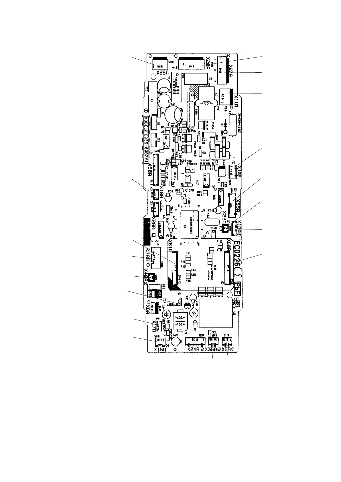
Si12-619A Printed Circuit Board Connector Wiring Diagram
PCB Detail PCB(1): Control PCB (A1P) (indoor unit)
X25A
X18A
X20A
X27A
X11A
X10A
X33A
Capacity
setting
adaptor
X61A
X36A
X40A
HAP
(Service
monitor LED)
X17A
X15A
X19A
X60A
X5AX35AX24A
2P095006
Printed Circuit Board Connector Wiring Diagram 65

Printed Circuit Board Connector Wiring Diagram Si12-619A
PCB Detail PCB(2): Signal Receiver PCB (A3P)
SS2
X1A
PCB(3): Display PCB (A4P)
LED4
X1A BS1
LED3 LED2 LED1
X2A
(R4873)
(R4874)
66 Printed Circuit Board Connector Wiring Diagram

Si12-619A Printed Circuit Board Connector Wiring Diagram
1.6 Outdoor Units – E Series (50-58 Class, 80-100 Class)
Connectors PCB(1)(Main PCB)
1) S10 Connector for terminal strip (indoor-outdoor transmission)
2) S15 Connector for COOL / HEAT mode lock
3) S20 Connector for electronic expansion valve coil A port (white)
4) S21 Connector for electronic expansion valve coil B port (red)
5) S22 Connector for electronic expansion valve coil C port (blue)
6) S23 Connector for electronic expansion valve coil D port (yellow)
7) S40 Connector for overload protector
8) S51, S101 Connector for service monitor PCB
9) S70 Connector for fan motor
10) S80 Connector for four way valve coil
11) S90 Connector for thermistors
(outdoor air, heat exchanger, and discharge pipe)
12) S92 Connector for gas pipe thermistor
13) S93 Connector for liquid pipe thermistor
14) AC1, AC2 Connector for terminal strip (power supply)
15) HR1, HR2 Connector for reactor
PCB(2)(Service Monitor PCB)
1) S52, S102 Connector for control PCB
Note: Other Designations
PCB(1)(Main PCB)
1) FU1 Fuse (30A)
2) FU2, FU3 Fuse (3.15A)
3) V2, V3, V5
V6, V11
V9, V100
PCB(2)(Service Monitor PCB)
1) LED A Service monitor LED (green)
2) LED1 - LED4 Service monitor LED (red)
3) SW1 Forced operation ON/OFF switch
4) SW3 Wiring error check switch
5) SW4 Priority room setting switch
6) SW5 Night quiet mode setting switch
Varistor
(for 50-58 class models)
(for 80-100 class models)
Printed Circuit Board Connector Wiring Diagram 67

Printed Circuit Board Connector Wiring Diagram Si12-619A
PCB Detail PCB(1): Main PCB (50-58 class models)
V3 V11AC1 FU2(3.15A)
FU1
(30A)
V2
V6
AC2
S15
S10
S101
V5
HR1
HR2
S80
FU1
(30A)
V2
V9
AC2
S10
S23
S22
S21
S92
S40S20 S70S90S93
PCB(1): Main PCB (80-100 class models)
V3AC1 FU2(3.15A)
S51
FU3(3.15A)
(R6041)
V100
HR1
HR2
S5
S101
V5
S80
S40S20S21S22S23 S70S90S92S93S24 S51
FU3(3.15A)
(R6060)
68 Printed Circuit Board Connector Wiring Diagram

Si12-619A Printed Circuit Board Connector Wiring Diagram
PCB(2): Service Monitor PCB
Printed Circuit Board Connector Wiring Diagram 69

Printed Circuit Board Connector Wiring Diagram Si12-619A
1.7 Outdoor Units – E Series (68-75 Class)
Connectors
Control PCB
1) S10 Connector for terminal strip (indoor - outdoor transmission)
2) S20 Connector for electronic expansion valve coil A port
3) S21 Connector for electronic expansion valve coil B port
4) S22 Connector for electronic expansion valve coil C port
5) S31 Connector for CN14 on SPM
6) S32 Connector for CN11 on SPM
7) S33 Connector for S34 on inverter PCB (MID2)
8) S40 Connector for overload protector
9) S51 Connector for S52 on service monitor PCB
10) S52 Connector for S51 on PCB
11) S71 Connector for S72 on inverter PCB (MID2)
12) S80 Connector for four way valve coil
13) S90 Connector for thermistors
(outdoor air, heat exchanger, and discharge pipe)
14) S91 Connector for fin thermistor
15) S92 Connector for gas pipe thermistor
16) S93 Connector for liquid pipe thermistor
17) S101 Connector for S102 on service monitor PCB
18) S102 Connector for S101 on PCB1
19) AC1 Connector for HAC1 or filter PCB
20) AC2 Connector for terminal strip (power supply)
21) E Connector for earth
22) H1, H2 Connector for diode bridge
23) LED A, LED1 to 4 Service monitor LED
24) FU2 Fuse (3.15 A)
25) V2, V5 Varistor
Filter PCB
(PCB 3)
Inverter PCB
(MID 2)
1) FU1 Fuse (30A)
2) V3 Varistor
3) HAC1 Connector for AC1 or PCB
4) HE2 Connector for earth
5) HL Connector for terminal strip (Power supply)
1) S34 Connector for S33 on PCB
2) S70 Connector for fan motor
3) S72 Connector for S71 on PCB
4) FU201 Fuse (3.15A)
5) N, U, V, W Connector for compressor
70 Printed Circuit Board Connector Wiring Diagram

Si12-619A Printed Circuit Board Connector Wiring Diagram
SPM
1) CN11 Connector for S32 on PCB
2) CN14 Connector for S31 on PCB
3) L1, L2 Connector for reactor
PCB Detail PCB (1): Control PCB (outdoor unit)
PCB (2): Service monitor PCB
ES102 AC1 V2 AC2 V5 FU2
S52
LED A
LED 1
LED 2
LED 3
LED 4
S10
S51
S101
H1
H2
S32
S33
S71
S31
S23S80
S93 S22 S21 S91S92 S20 S90 S40
2P138922
PCB (3): Filter PCB
HL
HE2
V3
Printed Circuit Board Connector Wiring Diagram 71
FU1
HAC1
3P179175

Printed Circuit Board Connector Wiring Diagram Si12-619A
Inverter PCB (MID2)
S72
W VUN
S34
S70
FU201
(3.15A)
3P080085
SPM
CN14
CN11L1L2
3EB10032
72 Printed Circuit Board Connector Wiring Diagram

Si12-619A Printed Circuit Board Connector Wiring Diagram
1.8 Outdoor Units – D Series
Connectors
Control PCB
1) S10 Connector for S11 on MID1
2) S20 Connector for electronic expansion valve coil A port
3) S21 Connector for electronic expansion valve coil B port
4) S22 Connector for electronic expansion valve coil C port
5) S23 Connector for electronic expansion valve coil D port
6) S31 Connector for CN14 on SPM
7) S32 Connector for CN11 on SPM
8) S33 Connector for S34 on inverter PCB (MID2)
9) S40 Connector for overload protector
10) S51 Connector for S52 on service monitor PCB
11) S52 Connector for S51 on PCB
12) S71 Connector for S72 on inverter PCB (MID2)
13) S80 Connector for four way valve coil
14) S90 Connector for thermistors
(outdoor air, heat exchanger, and discharge pipe)
15) S91 Connector for fin thermistor
16) S92 Connector for gas pipe thermistor
17) S93 Connector for liquid pipe thermistor
18) S101 Connector for S102 on service monitor PCB
19) S102 Connector for S101 on PCB
20) AC1 Connector for HL on MID1
21) AC2 Connector for HN on MID1
22) E Connector for earth
23) H1, H2 Connector for diode bridge
24) LED A, LED1 to 4 Service monitor LED
25) FU2 Fuse (3.15 A)
26) V2, V5 Varistor
MID 1
Inverter PCB
(MID 2)
1) S11 Connector for S10 on PCB1
2) FU1 Fuse (30A)
3) V3 Varistor
4) HE Connector for earth
5) HL Connector for AC1 on PCB
6) HN Connector for AC2 on PCB
1) S34 Connector for S33 on PCB
2) S70 Connector for fan motor
3) S72 Connector for S71 on PCB
4) FU201 Fuse (3.15A)
5) N, U, V, W Connector for compressor
Printed Circuit Board Connector Wiring Diagram 73

Printed Circuit Board Connector Wiring Diagram Si12-619A
SPM
1) CN11 Connector for S32 on PCB
2) CN14 Connector for S31 on PCB
3) L1, L2 Connector for reactor
PCB Detail PCB (1): Control PCB (outdoor unit)
PCB (2): Service monitor PCB
ES102 AC1 V2 AC2 V5 FU2
S52
LED A
LED 1
LED 2
LED 3
LED 4
S10
S51
S101
H1
H2
S32
S33
S71
S31
S23S80
S93 S22 S21 S91S92 S20 S90 S40
2P138922
MID1
HL
HE2
V3
74 Printed Circuit Board Connector Wiring Diagram
FU1
HAC1
3P179175

Si12-619A Printed Circuit Board Connector Wiring Diagram
Inverter PCB (MID2)
S72
W VUN
S34
S70
FU201
(3.15A)
3P080085
SPM
CN14
CN11L1L2
3EB10032
Printed Circuit Board Connector Wiring Diagram 75

Printed Circuit Board Connector Wiring Diagram Si12-619A
76 Printed Circuit Board Connector Wiring Diagram

Si12-619A
Part 4
Function and Control
1. Main Functions......................................................................................78
1.1 Frequency Principle................................................................................78
1.2 Power-Airflow Dual Flaps, Wide Angle Louvers and Auto-Swing ..........80
1.3 Fan Speed Control for Indoor Units........................................................81
1.4 Programme Dry Function .......................................................................82
1.5 Automatic Operation...............................................................................83
1.6 Thermostat Control.................................................................................84
1.7 Night Set Mode.......................................................................................85
1.8 ECONO Mode ........................................................................................86
1.9 MOLD PROOF Operation ......................................................................87
1.10 INTELLIGENT EYE (Wall Mounted Type Only) .....................................88
1.11 HOME LEAVE Operation .......................................................................90
1.12 Inverter POWERFUL Operation .............................................................91
1.13 Other Functions......................................................................................92
2. Function of Main Structural Parts..........................................................94
2.1 Main Structural Parts ..............................................................................94
2.2 Function of Thermistor ...........................................................................95
3. Control Specification .............................................................................99
3.1 Mode Hierarchy ......................................................................................99
3.2 Frequency Control................................................................................100
3.3 Controls at Mode Changing / Start-up..................................................103
3.4 Discharge Pipe Temperature Control...................................................104
3.5 Input Current Control ............................................................................104
3.6 Freeze-up Protection Control ...............................................................105
3.7 Heating Peak-cut Control .....................................................................105
3.8 Fan Control...........................................................................................106
3.9 Liquid Compression Protection Function 2...........................................106
3.10 Defrost Control .....................................................................................107
3.11 Low Hz High Pressure Limit .................................................................108
3.12 Electronic Expansion Valve Control .....................................................108
3.13 Malfunctions .........................................................................................112
3.14 Forced Operation Mode .......................................................................113
3.15 Wiring-Error Check ...............................................................................114
3.16 Additional Function...............................................................................116
Function and Control 77

Main Functions Si12-619A
1. Main Functions
Note: See the list of functions for the functions applicable to different models.
1.1 Frequency Principle
Main Control
Parameters
Additional
Control
Parameters
The compressor is frequency-controlled during normal operation. The target frequency is set by
the following 2 parameters coming from the operating indoor unit:
The load condition of the operating indoor unit
The difference between the room temperature and the set temperature
The target frequency is adapted by additional parameters in the following cases:
Frequency restrictions
Initial settings
Forced cooling / heating operation
Inverter Principle To regulate the capacity, a frequency control is needed. The inverter makes it possible to vary
the rotation speed of the compressor. The following table explains the conversion principle:
Phase Description
1 The supplied AC power source is converted into the DC power source for the present.
2 The DC power source is reconverted into the three phase AC power source with variable
frequency.
When the frequency increases, the rotation speed of the compressor increases resulting
in an increased refrigerant circulation. This leads to a higher amount of the heat
exchange per unit.
When the frequency decreases, the rotation speed of the compressor decreases
resulting in a decreased refrigerant circulation. This leads to a lower amount of the heat
exchange per unit.
Drawing of
Inverter
The following drawing shows a schematic view of the inverter principle:
Refrigerant circulation rate (high)
Amount of heat
exchanged air (large)
Amount of heat
exchanged air (small)
AC
power
freq=
constant
high f
DC
power
low f
50 Hz
freq=variable
60 Hz
Refrigerant circulation rate (low)
high speed
low speed
capacity=
variable
Amount of heat
exchanged air (large)
Amount of heat
exchanged air (small)
(R2812)
78 Function and Control

Si12-619A Main Functions
Inverter Features The inverter provides the following features:
The regulating capacity can be changed according to the changes in the outdoor air
temperature and cooling / heating load.
Quick heating and quick cooling
The compressor rotational speed is increased when starting the heating (or cooling). This
enables a quick set temperature.
Air discharge
temperature
45˚C
inverter
normal heat pump
Start
Even during extreme cold weather, the high capacity is achieved. It is maintained even when
60 120 300
seconds
(R1187)
the outdoor air temperature is 2°C.
Comfortable air conditioning
A detailed adjustment is integrated to ensure a fixed room temperature. It is possible to air
condition with a small room temperature variation.
Energy saving heating and cooling
Once the set temperature is reached, the energy saving operation enables to maintain the
room temperature at low power.
Frequency Limits The following table shows the functions that define the minimum and maximum frequency:
Frequency limits Limited during the activation of following functions
Low Four way valve operation compensation. Refer to page 103.
Forced Cooling /
High Input current control. Refer to page 104.
For more information, refer to “Forced operation mode” on page 113.
Compressor protection function. Refer to page 103.
Heating Peak-cut control. Refer to page 105.
Freeze-up protection. Refer to page 105.
Defrost control. Refer to page 107.
Heating Operation
Function and Control 79

Main Functions Si12-619A
1.2 Power-Airflow Dual Flaps, Wide Angle Louvers and
Auto-Swing
Power-airflow
Dual Flaps
The large flaps send a large volume of air downwards to the floor. The flap provides an optimum
control area in cooling, heating and dry mode.
Heating Mode
During heating mode, the large flap enables direct warm air straight downwards. The flap
presses the warm air above the floor to reach the entire room.
Cooling Mode
During cooling mode, the flap retracts into the indoor unit. Then, cool air can be blown far and
pervaded all over the room.
Wide-Angle
Louvers
The louvres, made of elastic synthetic resin, provide a wide range of airflow that guarantees a
comfortable air distribution.
Auto-Swing In case of FTK(X)S20-35D, FTK(X)S25/35E
The following table explains the auto swing process for heating, cooling, dry and fan :
Vertical Swing (up and down)
Cooling / Dry Heating Fan
°
10
50
°
(R4281)
°
30
°
65
(R4282)
Horizontal Swing
(right and left: manual)
°
5
°
70
(R4283)
45
°
°
45
(R4284)
3-D Airflow Wall Mounted Type 50-71 Class
Alternative repetition of vertical and horizontal swing motions enables uniform airconditioning of the entire room. This function is effective for starting the air conditioner.
When the horizontal swing and vertical swing are both set to auto mode, the airflow become
3-D airflow and the horizontal swing and vertical swing motions are alternated. The order of
swing motion is such that it turns counterclockwise, starting from the right upper point as
viewed to the front side of the indoor unit.
(R1024)
80 Function and Control

Si12-619A Main Functions
1.3 Fan Speed Control for Indoor Units
Control Mode The airflow rate can be automatically controlled depending on the difference between the set
temperature and the room temperature. This is done through rotation speed control, or phase
and Hall IC control.
For more information about Hall IC, refer to the troubleshooting for fan motor on page 214.
Fan speed Steps Phase control and fan speed control contains 9 steps: LLL, LL, SL, L, ML, M, MH, H and HH.
In automatic operation, the step “SL” is not available.
Wall mounted type 50-60 class Wall mounted type 20-35 class, 71 class
Step Cooling Heating Cooling Heating
LLL
LL
L
ML
M
MH
H
(R6037)
(R6036)
HH (Powerful) H+90 H+90 H+50 H+50
= Within this range the airflow rate is automatically controlled when the FAN setting
button is set to automatic.
Duct connected type
Floor standing type
Floor/ceiling suspended type
(R6037)
(R6036)
Note: 1. Fan stops during defrost operation.
Automatic Air
Flow Control for
Heating
Automatic Air
Flow Control for
Cooling
2. In time of thermostat OFF, the fan rotates at the following speed.
Cooling : The fan keeps rotating at the set tap.
Heating : The fan stops.
On heating mode, the indoor fan speed will be regulated according to the indoor heat exchanger
temperature and the difference between the room temperature and the required set point.
The following drawing explains the principle of fan speed control for cooling:
fan speed
Thermostat
setting
temperature
M
ML
+1.5˚C
L
+0.5˚C
DC motor: Rotation speed control
AC motor: Phase control
Difference between room
+2˚C
and set temperature
+1˚C
(R4594)
Function and Control 81
Main Functions Si12-619A
1.4 Programme Dry Function
Programme dry function removes humidity while preventing the room temperature from
lowering.
Since the microcomputer controls both the temperature and air flow volume, the temperature
adjustment and fan adjustment buttons are inoperable in this mode.
In Case of
Inverter Units
The microcomputer automatically sets the temperature and fan settings. The difference
between the room temperature at startup and the temperature set by the microcomputer is
divided into two zones. Then, the unit operates in the dry mode with an appropriate capacity for
each zone to maintain the temperature and humidity at a comfortable level.
Room temperature at
startup
24ºC or more
23.5ºC
~
18ºC
17.5ºC
~
Set temperature
X
Room temperature at
startup
18ºC X
Zone C = Thermostat ON
Thermostat OFF pointYThermostat ON point
2.5ºC
–
X
X
2.0ºC
–
2.0ºC
–
Z
Y + 0.5ºC (zone B)
continues for 10 min.
Y + 0.5ºC (zone B)
continues for 10 min.
X
Y + 0.5ºC (zone B)
continues for 10 min.
Z
0.5ºC
–
X
or
X
0.5ºC
–
or
0.5ºC = 17.5ºC
–
or
Zone B
Y
Zone A = Thermostat OFF
Zone B
+0.5ºC
(R6841)
82 Function and Control

Si12-619A Main Functions
Setpoint +2.5ºC
Setpoint –2.0ºC
=Thermostat OFF
Setpoint +1.5ºC
=Thermostat OFF
1.5 Automatic Operation
Automatic Cooling / Heating Function (Heat Pump Only)
When the AUTO mode is selected with the remote controller, the microcomputer automatically
determines the operation mode from cooling and heating according to the room temperature
and setting temperature at the time of the operation startup, and automatically operates in that
mode.
The unit automatically switches the operation mode to cooling or heating to maintain the room
temperature at the main unit setting temperature.
Detailed
Explanation of
the Function
1. Remote controller setting temperature is set as automatic cooling / heating setting
temperature (18 to 30°C).
2. Main unit setting temperature equals remote controller setting temperature.
3. Operation ON / OFF point and mode switching point are as follows.
Heating
Room temperature
Cooling
Cooling switching point:
→
Main unit setting temperature +2.5 deg.
≥
Heating switching point:
→
Room temperature < Main unit setting temperature –2.5 deg.
Thermostat ON / OFF point is the same as the ON / OFF point of cooling or heating
operation.
4. During initial operation
Room temperature
Remote controller setting temperature: Cooling operation
≥
Room temperature < Remote controller setting temperature: Heating operation
Cooling Operation
Setpoint –2.5ºC
Heating Operation
Ex: When the set point is 25°C
Cooling Operation
Heating Operation
→
→
(R6842)
23°C: Thermostat OFF
22°C: Switch to Heating Operation
→
26.5°C: Thermostat OFF → 27.5°C: Switch to Cooling Operation
Function and Control 83

Main Functions Si12-619A
1.6 Thermostat Control
Thermostat control is based on the difference between the room temperature and the setpoint.
Thermostat OFF Condition
The temperature difference is in the zone A.
Thermostat ON Condition
The temperature difference is above the zone C after being in the zone A.
The system resumes from defrost control in any zones except A.
The operation turns on in any zones except A.
The monitoring time has passed while the temperature difference is in the zone B.
(Cooling / Dry : 10 minutes, Heating : 10 seconds)
Cooling / Dry
Wall Mounted Type
Room temperature - setpoint
ON
Cooling : – 0.5˚C
C
Dry : – 0.5˚C
Heating
B
A
OFF
Floor standing Type
Floor/Ceiling suspended Type
Duct Connected Type
C
– 1.5˚C
B
A
OFF
Wall Mounted Type
OFF
A
B
C
Cooling : – 2.0˚C
Dry : – 2.5~– 2.0˚C
Room temperature - setpoint
ON
Cooling : – 1.0˚C
Dry : – 1.0˚C
Cooling : – 2.0˚C
Dry : – 2.5~– 2.0˚C
Room temperature - setpoint
1.5˚C
0˚C
(R4668)
(R6032)
ON
Floor standing Type
Floor/Ceiling suspended Type
Duct Connected Type
OFF
A
B
1.0˚C
C
Room temperature - setpoint
1.5˚C
0.5˚C
ON
(R4669)
(R6033)
84 Function and Control

Si12-619A Main Functions
1.7 Night Set Mode
When the OFF timer is set, the Night Set circuit automatically activates.
The Night Set circuit maintains the airflow setting made by users.
The Night Set
Circuit
Cooling
Operation
The Night Set circuit continues heating or cooling the room at the set temperature for the first
one hour, then automatically raises the temperature setting slightly in the case of cooling, or
lowers it slightly in the case of heating, for economical operations. This prevents excessive
heating in winter and excessive cooling in summer to ensure comfortable sleeping conditions,
and also conserves electricity.
In case of FTK(X)S25-35E, FTK(X)S20-35D, FTK(X)S50-71F the temperature rises once.
Heating
Operation
Function and Control 85

Main Functions Si12-619A
1.8 ECONO Mode
Outline FTK(X)S20-35D, FTK(X)S25/35E
The "ECONO mode" reduces the maximum operating current and power consumption by
approx. 30% during start up etc..
This mode is particularly convenient for energy-saving-oriented users. It is also a major bonus
for those whose breaker capacities do not allow the use of multiple electrical devices and air
conditioners.
It is easily activated from the wireless remote controller by pushing the ECONO button.
When this function is ON, the maximum capacity is also down. (Approx. 20%)
This function can only be set when the unit is running. Pressing the operation stop button
causes the settings to be canceled.
This function and POWERFUL operation cannot be used at the same time. The latest
command has the priority.
Powe r
consumption
and current
Normal
Details
Econo Mode
Time
(R4607)
ECONO mode can be activated while the unit is running. The remote controller can send the
ECONO command when the unit is in COOL, HEAT, DRY, or AUTO operation.
When the ECONO command is valid, the upper limit of frequency is restricted.
Refer to page 117 for "ECONO-mode-proof setting".
86 Function and Control

Si12-619A Main Functions
1.9 MOLD PROOF Operation
FTK(X)S20-35D, FTK(X)S25/35E
MOLD PROOF operation is a function which reduces the spread of mold by using Fan mode to
lower the humidity inside the indoor unit.
Outline MOLD PROOF operation starts when the following conditions are met.
1. MOLD PROOF is set on the remote controller.
2. Cooling or dry operation stops.
MOLD PROOF operation will operate for approximately one hour after dry or cooling mode
is turned off.
The indoor fan rotates at 550 rpm.
Note: 1. This function is not designed to remove existing dust or mold.
2. MOLD PROOF operation is not available when the unit is turned off using the OFF TIMER.
Function and Control 87
 Loading...