

Daikin 2MXU40GV1B, 2MXU50GV1B Installation manuals

OUTDOOR UNIT
INSTALLATION MANUAL
R410A Split Series
EnglishDeutschFrançaisNederlandsEspañolItaliano
MODELS
2MXU40GV1B
2MXU50GV1B
ΕλληνικÜ
Portugues
Рóссêий
Türkçe
DAIKIN.TCF.015 M7/10-2008
KEMA Quality B.V.
74736-KRQ/EMC97-4957
Umeda Center Bldg., 2-4-12, Nakazaki-Nishi,
Kita-ku, Osaka, 530-8323 Japan
*
Low Voltage 2006/95/EC
Electromagnetic Compatibility 2004/108/EC
Noboru Murata
Manager Quality Control Department
1st. of Nov. 2008
DAIKIN INDUSTRIES, LTD.
2MXU40GV1B, 2MXU50GV1B
3SB64418-1
Safety Precautions
• The precautions described herein are classified as WARNING and CAUTION. They both contain important
information regarding safety. Be sure to observe all precautions without fail.
• Meaning of WARNING and CAUTION notices
WARNING .... Failure to follow these instructions properly may result in personal injury or loss of life.
CAUTION .....Failure to observe these instructions properly may result in property damage or personal injury, which
may be serious depending on the circumstances.
• The safety marks shown in this manual have the following meanings:
Be sure to follow the instructions. Be sure to establish an earth connection. Never attempt.
• After completing installation, conduct a trial operation to check for faults and explain to the customer how to operate
the air conditioner and take care of it with the aid of the operation manual.
WARNING
• Ask your dealer or qualified personnel to carry out installation work.
Do not attempt to install the air conditioner yourself. Improper installation may result in water leakage, electric shocks or fire.
• Install the air conditioner in accordance with the instructions in this installation manual.
Improper installation may result in water leakage, electric shocks or fire.
• Be sure to use only the specified accessories and parts for installation work.
Failure to use the specified parts may result in the unit falling, water leakage, electric shocks or fire.
• Install the air conditioner on a foundation strong enough to withstand the weight of the unit.
A foundation of insufficient strength may result in the equipment falling and causing injury.
• Electrical work must be performed in accordance with relevant local and national regulations and with instructions
in this installation manual. Be sure to use a dedicated power supply circuit only.
Insufficiency of power circuit capacity and improper workmanship may result in electric shocks or fire.
• Use a cable of suitable length.
Do not use tapped wires or an extension lead, as this may cause overheating, electric shocks or fire.
• Make sure that all wiring is secured, the specified wires are used, and that there is no strain on the terminal
connections or wires.
Improper connections or securing of wires may result in abnormal heat build-up or fire.
• When wiring the power supply and connecting the wiring between the indoor and outdoor units, position the wires
so that the control box lid can be securely fastened.
Improper positioning of the control box lid may result in electric shocks, fire or over heating terminals.
• If refrigerant gas leaks during installation, ventilate the area immediately.
Toxic gas may be produced if the refrigerant comes into contact with fire.
• After completing installation, check for refrigerant gas leakage.
into the room and comes into contact with a source of fire, such as a fan heater, stove or cooker.
• When installing or relocating the air conditioner, be sure to bleed the refrigerant circuit to ensure it is free of air, and
use only the specified refrigerant (R410A).
The presence of air or other foreign matter in the refrigerant circuit causes abnormal pressure rise, which may result in equipment damage and even injury.
• During installation, attach the refrigerant piping securely before running the compressor.
If the compressor is not attached and the stop valve is open when the compressor is run, air will be sucked in, causing abnormal pressure in
the refrigeration cycle, which may result in equipment damage and even injury.
• During pump-down, stop the compressor before removing the refrigerant piping.
If the compressor is still running and the stop valve is open during pump-down, air will be sucked in when the refrigerant piping is removed,
causing abnormal pressure in the refrigeration cycle, which may result in equipment damage and even injury.
• Be sure to earth the air conditioner.
Imperfect earthing may result in electric shocks.
Do not earth the unit to a utility pipe, lightning conductor or telephone ear th lead.
• Be sure to install an earth leakage breaker.
Failure to install an earth leakage breaker may result in electric shocks or fire.
Toxic gas may be produced if the refrigerant gas leaks
CAUTION
• Do not install the air conditioner at any place where there is a danger of flammable gas leakage.
In the event of a gas leakage, build-up of gas near the air conditioner may cause a fire to break out.
• While following the instructions in this installation manual, install drain piping to ensure proper drainage and
insulate piping to prevent condensation.
Improper drain piping may result in indoor water leakage and property damage.
• Tighten the flare nut according to the specified method such as with a torque wrench.
If the flare nut is too tight, it may crack after prolonged use, causing refrigerant leakage.
•
Make sure to provide for adequate measures in order to prevent that the outdoor unit be used as a shelter by small animals.
Small animals making contact with electrical parts can cause malfunctions, smoke or fire. Please instruct the customer to keep the area around the unit clean.
1 ■English
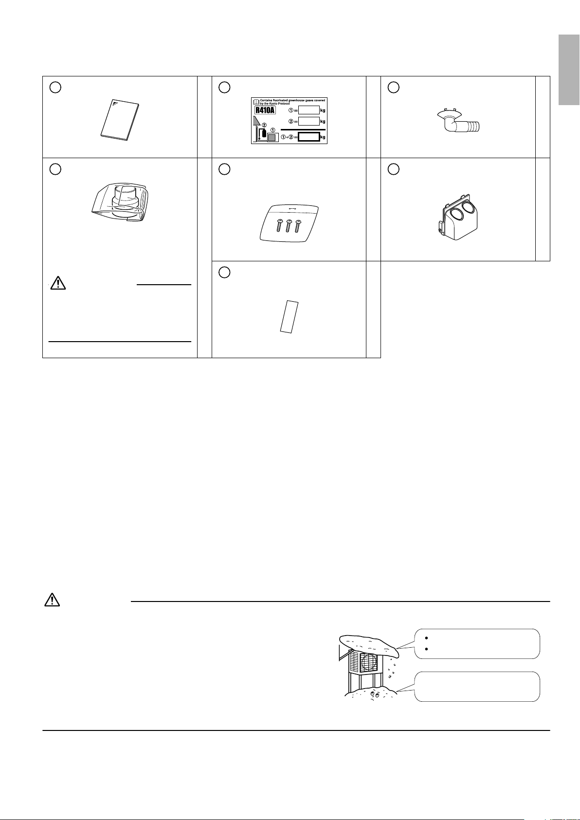
Accessories
Accessories supplied with the outdoor unit:
Installation Manual
A B C
1
There is on the bottom packing case.
Reducer assy (Only 50 class)
D E F
The reducer assy is attached to the
stop valve mounting plate inside the
stop valve cover.
1
CAUTION
Remove the reducer assy from the
stop valve mounting plate before
installing the outdoor unit regardless
of whether the assy has been used.
Refrigerant charge label
There is on the bottom packing case.
Screw bag
(For fixing the wire retainer and
humidifying hose cover)
There is on the bottom packing case.
Multilingual fluorinated
G
greenhouse gases label
There is on the bottom packing case.
1
1
1
Drain plug
There is on the bottom packing case.
Humidifying hose cover
English
1
1
Precautions for Selecting the Location
1) Choose a place solid enough to bear the weight and vibration of the unit, where the operation noise will not be amplified.
2) Choose a location where the hot air discharged from the unit or the operation noise, will not cause a nuisance to the
neighbors of the user.
3) Avoid places near a bedroom and the like, so that the operation noise will cause no trouble.
4) There must be sufficient spaces for carrying the unit into and out of the site.
5) There must be sufficient space for air passage and no obstructions around the air inlet and the air outlet.
6) The site must be free from the possibility of flammable gas leakage in a nearby place.
Locate the unit so that the noise and the discharged hot air will not annoy the neighbors.
7) Install units, power cords and inter-unit cables at least 3m away from television and radio sets. This is to prevent interference to images and sounds. (Noises may be heard even if they are more than 3m away depending on radio wave
conditions.)
In coastal areas or other places with salty atmosphere of sulfate gas, corrosion may shorten the life of the air conditioner.
8)
9) Since drain flows out of the outdoor unit, do not place under the unit anything which must be kept away from moisture.
NOTE:
Cannot be installed hanging from ceiling or stacked.
CAUTION
When operating the air conditioner in a low outdoor ambient temperature, be sure to follow the instructions described below.
1) To prevent exposure to wind, install the outdoor unit with its suction
side facing the wall.
2) Never install the outdoor unit at a site where the suction side may
be exposed directly to wind.
3) To prevent exposure to wind, it is recommended to install a baffle
plate on the air discharge side of the outdoor unit.
4) In heavy snowfall areas, select an installation site where the snow
will not affect the unit.
Construct a large canopy.
Construct a pedestal.
Install the unit high enough off the
ground to prevent burying in snow.
■English 2
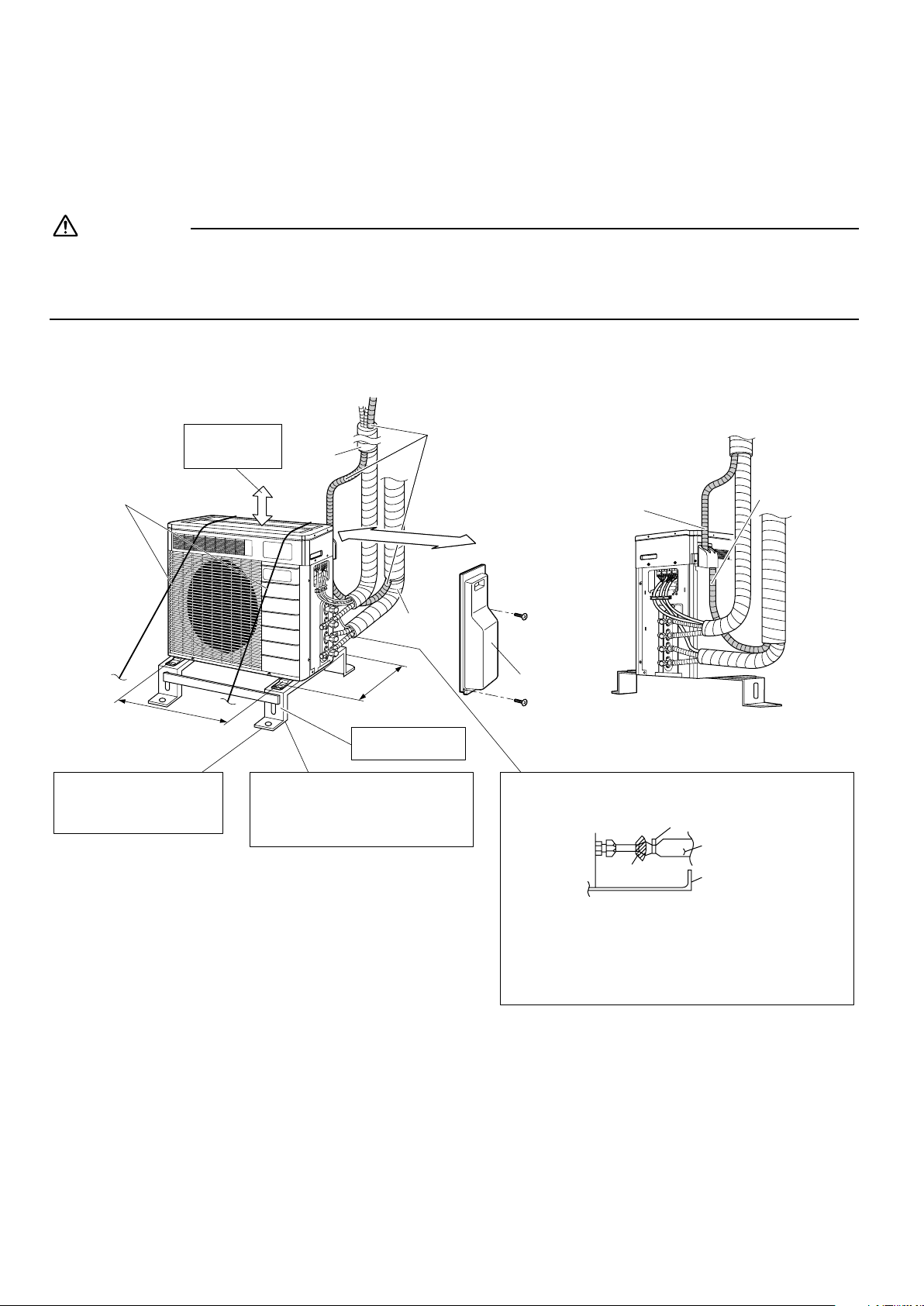
Outdoor Unit Installation Drawings
1.
Precautions for humidifying hose installation work.
• Moisture on the outdoor unit is brought to the indoor unit together with air around the outdoor unit during humidifying
operation. Install the outdoor unit in a clean and calm location.
• Be sure to use the humidifying hose sold as an optional accessory. (KPMH996A10S (10m set), KPMH996A15S (15m set))
CAUTION
Do not connect the embedded branch piping and the outdoor unit when only carrying out piping work without connecting the
indoor unit in order to add another indoor unit later.
Make sure no dirt or moisture gets into either side of the embedded branch piping.
See “Precautions for Laying Refrigerant Piping” on page 9 for details.
Installation of humidifying hoses, respectively, in upward direction in ROOM A and in downward direction
in ROOM B.
<Front side> <Back side>
Wire
(Hole pitch of foot bolts)
If there is the danger of the unit
falling or overturning, fix the unit
with foundation bolts, or with wire
or other means.
Allow 300mm of
work space below
the ceiling surface.
574
ROOM A
250mm from wall
311
(Hole pitch of
foot bolts)
Level mounting base
(available separately)
If the location does not have good drainage,
place the unit on a level mounting base (or a
plastic pedestal). Install the outdoor unit in a
level position. Failure to do so may result in
water leakage or accumulation.
Humidifying hose
Humidifying hose
ROOM A
ROOM B
Stop valve cover
Also insulate the connection on the outdoor unit.
Clamping material
Humidifying hose
ROOM B
unit: mm
Insulation tube
Tape
Stop valve cover
Use tape or insulating material on all connections
to prevent air from getting in between the copper
piping and the insulation tube.
Be sure to do this if the outdoor unit is installed
above.
3 ■English
Installation
• Install the unit horizontally.
• The unit may be installed directly on a concrete verandah or a solid place if drainage is good.
• If the vibration may possibly be transmitted to the building, use a vibration-proof rubber (field supply).
Connections (connection port).
1.
Install the indoor unit according to the table below, which shows the relationship between the class of indoor unit and the
corresponding port.
The total indoor unit class that can be connected to this unit:
2MXU40G∗
2MXU50G∗
Up to 6.0kW
Up to 8.5kW
English
Por t
A
B
: Use a reducer to connect pipes.
Refer to “How to Use Reducers” for information on reducer numbers and their shapes.
25 , 35
25 , 35
2MXU50G∗2MXU40G∗
25,35,42
25,35,42,50
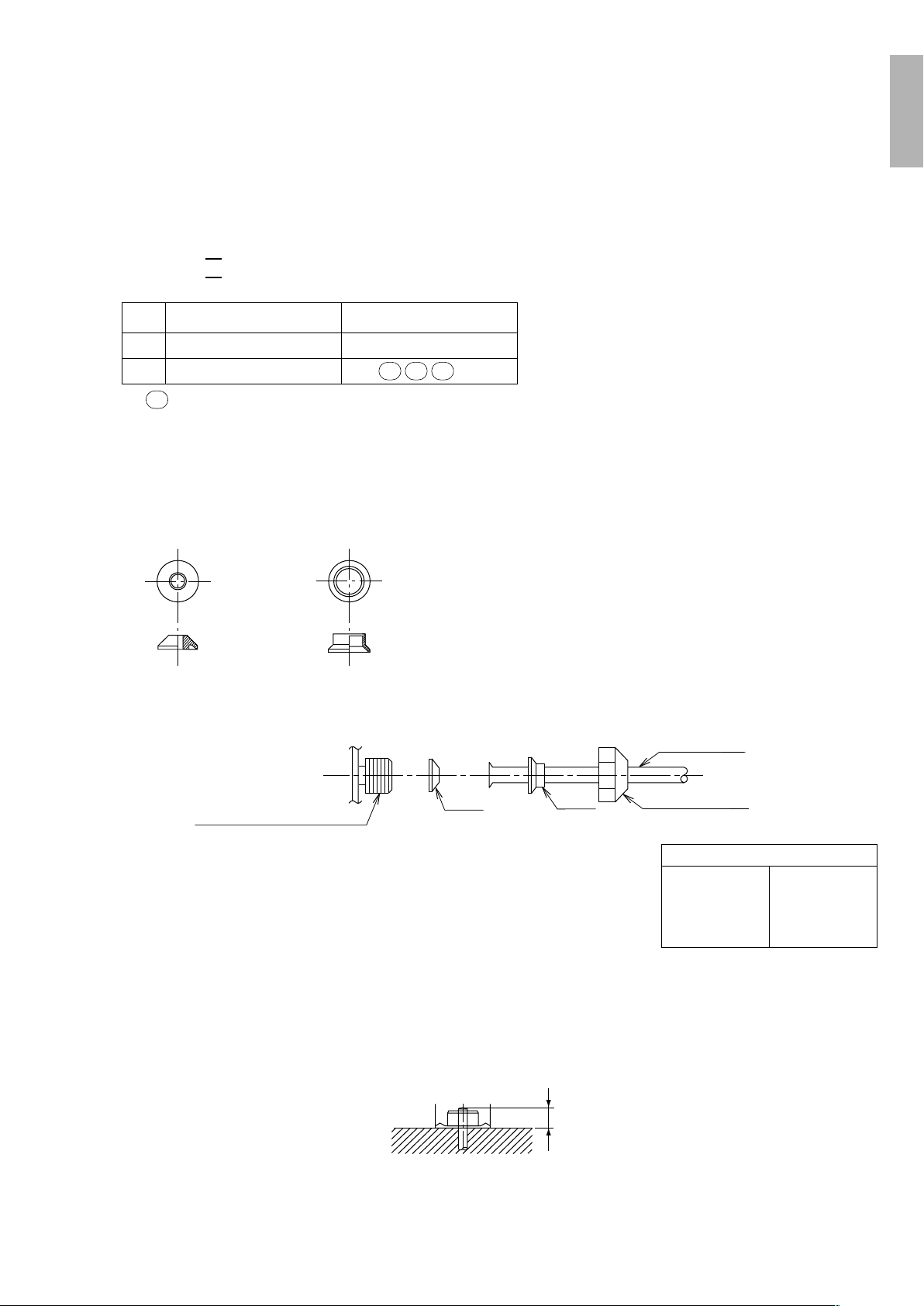
How to Use Reducers
No.1
φ12.7→ φ9.5
Gasket (1) Gasket (2)
Use the reducers supplied with the unit as described below.
• Connecting a pipe of φ9.5 to a gas pipe connection port for φ12.7:
No.2
φ12.7→ φ9.5
Inter-unit piping
Connection port of outdoor unit
• When using the reducer packing shown above, be careful not to overtighten
the nut, or the smaller pipe may be damaged (about 2/3 - 1 the normal torque).
• Apply a coat of refrigeration oil to the threaded connection port of the outdoor
unit where the flare nut comes in.
• Use an appropriate wrench to avoid damaging the connection thread by overtightening the flare nut.
Be sure to attach the gasket.
No. 1
No. 2
Flare nut (for φ12.7)
Flare nut tightening torque
Flare nut for
φ12.7
49.5–60.3N·m
(505–615kgf·cm)
Precautions on Installation
• Check the strength and level of the installation ground so that the unit will not cause any operating vibration or noise after installed.
• In accordance with the foundation drawing in fix the unit securely by means of the foundation bolts. (Prepare four sets of M8 or
M10 foundation bolts, nuts and washers each which are available on the market.)
• It is best to screw in the foundation bolts until their length are 20mm from the foundation surface.
20
■English 4
 Loading...