


 Loading...
DAHUA DH-XVR4104C-X, DH-XVR4108C-X, DH-XVR4116HS-X, DH-XVR4104HS-X, DH-XVR4108HS-X Users manual
...DIGITAL VIDEO RECORDER
User’s Manual
V1.1.0
ZHEJIANG DAHUA VISION TECHNOLOGY CO., LTD.

Cybersecurity Recommendations
Mandatory actions to be taken towards cybersecurity 1. Change Passwords and Use Strong Passwords:
The number one reason systems get “hacked” is due to having weak or default passwords. It is recommended to change default passwords immediately and choose a strong password whenever possible. A strong password should be made up of at least 8 characters and a combination of special characters, numbers, and upper and lower case letters.
2. Update Firmware
As is standard procedure in the tech-industry, we recommend keeping NVR, DVR, and IP camera firmware up-to-date to ensure the system is current with the latest security patches and fixes.
“Nice to have” recommendations to improve your network security
1. Change Passwords Regularly
Regularly change the credentials to your devices to help ensure that only authorized users are able to access the system.
2. Change Default HTTP and TCP Ports:
●Change default HTTP and TCP ports for systems. These are the two ports used to communicate and to view video feeds remotely.
●These ports can be changed to any set of numbers between 1025-65535. Avoiding the default ports reduces the risk of outsiders being able to guess which ports you are using.
3. Enable HTTPS/SSL:
Set up an SSL Certificate to enable HTTPS. This will encrypt all communication between your devices and recorder.
4. Enable IP Filter:
Enabling your IP filter will prevent everyone, except those with specified IP addresses, from accessing the system.
5. Change ONVIF Password:
On older IP Camera firmware, the ONVIF password does not change when you change the system’s credentials. You will need to either update the camera’s firmware to the latest revision or manually change the ONVIF password.
6. Forward Only Ports You Need:
●Only forward the HTTP and TCP ports that you need to use. Do not forward a huge range of numbers to the device. Do not DMZ the device's IP address.
●You do not need to forward any ports for individual cameras if they are all connected to a recorder on site; just the NVR is needed.
7. Disable Auto-Login on SmartPSS:
Those using SmartPSS to view their system and on a computer that is used by multiple people should disable auto-login. This adds a layer of security to prevent users without the appropriate credentials from accessing the system.
8. Use a Different Username and Password for SmartPSS:
Cybersecurity Recommendations I
In the event that your social media, bank, email, etc. account is compromised, you would not want someone collecting those passwords and trying them out on your video surveillance system. Using a different username and password for your security system will make it more difficult for someone to guess their way into your system.
9. Limit Features of Guest Accounts:
If your system is set up for multiple users, ensure that each user only has rights to features and functions they need to use to perform their job.
10. UPnP:
●UPnP will automatically try to forward ports in your router or modem. Normally this would be a good thing. However, if your system automatically forwards the ports and you leave the credentials defaulted, you may end up with unwanted visitors.
●If you manually forwarded the HTTP and TCP ports in your router/modem, this feature should be turned off regardless. Disabling UPnP is recommended when the function is not used in real applications.
11. SNMP:
Disable SNMP if you are not using it. If you are using SNMP, you should do so only temporarily, for tracing and testing purposes only.
12. Multicast:
Multicast is used to share video streams between two recorders. Currently there are no known issues involving Multicast, but if you are not using this feature, deactivation can enhance your network security.
13. Check the Log:
If you suspect that someone has gained unauthorized access to your system, you can check the system log. The system log will show you which IP addresses were used to login to your system and what was accessed.
14. Physically Lock Down the Device:
Ideally, you want to prevent any unauthorized physical access to your system. The best way to achieve this is to install the recorder in a lockbox, locking server rack, or in a room that is behind a lock and key.
Cybersecurity Recommendations II

Foreword
General
This user’s manual (hereinafter referred to be "the Manual") introduces the functions and operations of the DVR devices (hereinafter referred to be "the Device").
Models
|
|
Series |
|
|
Models |
|
|
|
XVR4 series |
|
|
DH-XVR4104C-X/DH-XVR4108C-X/DH-XVR4116HS-X/DH-XVR4104HS-X/ |
|
|
|
|
|
DH-XVR4108HS-X/DH-XVR4216AN-X/DH-XVR4232AN-X |
|
|
|
|
|
|
|
|
|
|
|
|
|
|
|
|
|
|
|
|
|
DH-XVR5108C-X/DH-XVR5104C-4KL-X/DH-XVR5104C-X/DH-XVR5108H-X/ |
|
|
|
|
|
|
DH-XVR5116H-X/DH-XVR5104H-4KL-X/DH-XVR5108H-4KL-X/ |
|
|
|
|
|
|
DH-XVR5116H-4KL-X/DH-XVR5108HE-X/DH-XVR5116HE-X/ |
|
|
|
|
|
|
DH-XVR5108HS-X/DH-XVR5116HS-X/DH-XVR5104HS-4KL-X/ |
|
|
|
XVR5 series |
|
|
DH-XVR5108HS-4KL-X/DH-XVR5104HS-X/DH-XVR5104H-X/ |
|
|
|
|
|
|
DH-XVR5104HE-X/DH-XVR5216AN-X/DH-XVR5232AN-X/ |
|
|
|
|
|
|
DH-XVR5208AN-4KL-X/DH-XVR5216AN-4KL-X/DH-XVR5216A-X/ |
|
|
|
|
|
|
DH-XVR5432L-X/DH-XVR5832S-X/DH-5208AN-4KL-X-8/ |
|
|
|
|
|
|
DH-5216AN-4KL-X-16P/DH-XVR5108H-4KL-X-8P |
|
|
|
|
|
|
|
|
|
|
|
|
|
DH-XVR7104E-4KL-X/DH-XVR7108E-4KL-X/DH-XVR7104E-4KL-B-X/ |
|
|
|
|
|
|
DH-XVR7108E-4KL-B-X/DH-XVR7104HE-4KL-X/ |
|
|
|
XVR7 series |
|
|
DH-XVR7108HE-4KL-X/DH-XVR7116HE-4KL-X/DH-XVR7108HE-4K-X/ |
|
|
|
|
|
|
DH-XVR7208A-4KL-X/DH-XVR7216A-4KL-X/DH-XVR7208A-4K-X/ |
|
|
|
|
|
|
DH-XVR7416L-4KL-X/ DH-XVR7816S-4KL-X |
|
|
|
|
|
|
|
|
Safety Instructions |
|
|
|
|
||
The following categorized signal words with defined meaning might appear in the Manual.
Signal Words |
Meaning |
|
Indicates a high potential hazard which, if not avoided, will result |
|
in death or serious injury. |
|
|
|
Indicates a medium or low potential hazard which, if not avoided, |
|
could result in slight or moderate injury. |
|
|
|
Indicates a potential risk which, if not avoided, could result in |
|
property damage, data loss, lower performance, or unpredictable |
|
result. |
|
|
|
Provides methods to help you solve a problem or save you time. |
|
|
Foreword III

Signal Words |
Meaning |
|
Provides additional information as the emphasis and supplement |
|
to the text. |
|
|
Revision History
No. |
Version |
Revision Content |
Release Time |
|
1 |
V1.0.0 |
First Release. |
February 27, 2018 |
|
|
|
|
|
|
2 |
V1.0.1 |
Add eight models. |
March 27, 2018 |
|
|
|
|
|
|
|
|
1. |
Add four models. |
|
|
|
2. |
Add following sections: |
|
|
|
|
Privacy Protection Notice |
|
|
|
|
Using Reset Button on the |
|
|
|
|
Mainboard |
|
|
|
|
Configuring White Light |
|
|
|
|
Configuring Siren |
|
3 |
V1.1.0 |
|
Viewing PoC Information |
May 10, 2018 |
|
|
3. |
Update following sections: |
|
|
|
|
About the Manual |
|
|
|
|
Important Safeguards and |
|
|
|
|
Warnings |
|
|
|
|
Configuring IVS Function |
|
|
|
|
Configuring Face |
|
|
|
|
Detection |
|
|
|
|
|
|
Privacy Protection Notice
As the device user or data controller, you might collect personal data of others' such as face, fingerprints, car plate number, Email address, phone number, GPS and so on. You need to be in compliance with the local privacy protection laws and regulations to protect the legitimate rights and interests of other people by implementing measures include but not limited to: providing clear and visible identification to inform data subject the existence of surveillance area and providing related contact.
About the Manual
The Manual is for reference only. If there is inconsistency between the Manual and the actual product, the actual product shall prevail.
We are not liable for any loss caused by the operations that do not comply with the Manual.
The Manual would be updated according to the latest laws and regulations of related regions. For detailed information, see the paper User's Manual, CD-ROM, QR code or our official website. If there is inconsistency between paper User's Manual and the electronic version, the electronic version shall prevail.
All the designs and software are subject to change without prior written notice. The product updates might cause some differences between the actual product and the Manual. Please
Foreword IV
contact the customer service for the latest program and supplementary documentation.
There still might be deviation in technical data, functions and operations description, or errors in print. If there is any doubt or dispute, please refer to our final explanation.
Upgrade the reader software or try other mainstream reader software if the Guide (in PDF format) cannot be opened.
All trademarks, registered trademarks and the company names in the Manual are the properties of their respective owners.
Please visit our website, contact the supplier or customer service if there is any problem occurred when using the device.
If there is any uncertainty or controversy, please refer to our final explanation.
Foreword V

 Important Safeguards and Warnings
This Chapter describes the contents covering proper handling of the Device, hazard prevention, and prevention of property damage. Read these contents carefully before using the Device, comply with them when using, and keep it well for future reference.
Operation Requirement
Do not place or install the Device in a place exposed to sunlight or near the heat source.
Keep the Device away from dampness, dust or soot.
Keep the Device installed horizontally on the stable place to prevent it from falling.
Do not drop or splash liquid onto the Device, and make sure there is no object filled with liquid on the Device to prevent liquid from flowing into the Device.
Install the Device in a well-ventilated place, and do not block the ventilation of the Device.
Operate the device within the rated range of power input and output.
Do not dissemble the Device.
Transport, use and store the Device under the allowed humidity and temperature conditions.
Electrical Safety
Improper battery use might result in fire, explosion, or inflammation.
When replacing battery, make sure the same model is used.
Use the recommended power cables in the region and conform to the rated power specification.
Use the power adapter provided with the Device; otherwise, it might result in people injury and device damage.
The power source shall conform to the requirement of the Safety Extra Low Voltage (SELV) standard, and supply power with rated voltage which conforms to Limited power Source requirement according to IEC60950-1. Please note that the power supply requirement is subject to the device label.
Connect the device (I-type structure) to the power socket with protective earthing.
The appliance coupler is a disconnection device. When using the coupler, keep the angle for easy operation.
Important Safeguards and Warnings VI

Table of Contents |
|
Cybersecurity Recommendations........................................................................................................... |
I |
Foreword .................................................................................................................................................. |
III |
Important Safeguards and Warnings .................................................................................................... |
VI |
1 Introduction............................................................................................................................................ |
1 |
1.1 Overview ....................................................................................................................................... |
1 |
1.2 Functions....................................................................................................................................... |
1 |
2 Getting Started ...................................................................................................................................... |
3 |
2.1 Checking the Components............................................................................................................ |
3 |
2.2 Installing HDD ............................................................................................................................... |
3 |
2.2.1 DH-XVR5108C-X/DH-XVR5104C-4KL-X/DH-XVR5104C-X/ |
|
DH-XVR4104C-X/DH-XVR4108C-X............................................................................................ |
4 |
2.2.2 DH-XVR7104E-4KL-X/DH-XVR7108E-4KL-X/DH-XVR7104E-4KL-B-X/ |
|
DH-XVR7108E-4KL-B-X.............................................................................................................. |
5 |
2.2.3 DH-XVR4116HS-X/DH-XVR5108HS-X/DH-XVR5116HS-X/DH-XVR5104HS-4KL-X/ |
|
DH-XVR5108HS-4KL-X/ |
|
DH-XVR5108H-X/DH-XVR5116H-X/DH-XVR5104H-4KL-X/DH-XVR5108H-4KL-X/DH-XVR511 |
|
6H-4KL-X/DH-XVR5108HE-X/DH-XVR5116HE-X/DH-XVR7104HE-4KL-X/DH-XVR7108HE-4K |
|
L-X/DH-XVR7116HE-4KL-X/DH-XVR7108HE-4K-X/DH-XVR5104HS-X/ |
|
DH-XVR4104HS-X/DH-XVR5104H-X/DH-XVR5104HE-X/DH-XVR4108HS-X ......................... |
6 |
2.2.4 DH-XVR4216AN-X/DH-XVR4232AN-X/DH-XVR5216AN-X/DH-XVR5232AN-X/ |
|
DH-XVR5208AN-4KL-X/DH-XVR5216AN-4KL-X/DH-XVR5216A-X/DH-XVR7208A-4KL-X/DH- |
|
XVR7216A-4KL-X/DH-XVR7208A-4K-X ..................................................................................... |
7 |
2.2.5 DH-XVR7416L-4KL-X/DH-XVR5432L-X............................................................................ |
7 |
2.2.6 DH-XVR7816S-4KL-X/DH-XVR5832S-X ........................................................................... |
8 |
2.3 Installing Device into Rack............................................................................................................ |
8 |
3 The Grand Tour.................................................................................................................................... |
10 |
3.1 Front Panel.................................................................................................................................. |
10 |
3.1.1 DH-XVR5108C-X/DH-XVR5104C-4KL-X/DH-XVR5104C-X/ |
|
DH-XVR4104C-X/DH-XVR4108C-X.......................................................................................... |
10 |
3.1.2 DH-XVR7104E-4KL-X/DH-XVR7108E-4KL-X/DH-XVR7104E-4KL-B-X/ |
|
DH-XVR7108E-4KL-B-X............................................................................................................. |
11 |
3.1.3 DH-XVR5108H-X/DH-XVR5116H-X/DH-XVR5104H-4KL-X/DH-XVR5108H-4KL-X/ |
|
DH-XVR5116H-4KL-X/DH-XVR5108HE-X/DH-XVR5116HE-X/DH-XVR4116HS-X/DH-XVR510 |
|
8HS-X/DH-XVR5116HS-X/DH-XVR5104HS-4KL-X/DH-XVR5108HS-4KL-X/ |
|
DH-XVR5104HS-X/DH-XVR4104HS-X/DH-XVR4108HS-X/DH-XVR5104H-X/ |
|
DH-XVR5104HE-X .................................................................................................................... |
12 |
3.1.4 DH-XVR7104HE-4KL-X/DH-XVR7108HE-4KL-X/DH-XVR7116HE-4KL-X/ |
|
DH-XVR7108HE-4K-X............................................................................................................... |
12 |
3.1.5 DH-XVR4216AN-X/DH-XVR4232AN-X/DH-XVR5216AN-X/DH-XVR5232AN-X/ |
|
DH-XVR5208AN-4KL-X/DH-XVR5216AN-4KL-X/DH-XVR5216A-X ........................................ |
13 |
3.1.6 DH-XVR7208A-4KL-X/DH-XVR7216A-4KL-X/DH-XVR7208A-4K-X............................... |
13 |
Table of Contents |
VII |
3.1.7 DH-XVR7416L-4KL-X....................................................................................................... |
14 |
3.1.8 DH-XVR7816S-4KL-X ...................................................................................................... |
14 |
3.1.9 DH-XVR5432L-X .............................................................................................................. |
14 |
3.1.10 DH-XVR5832S-X ............................................................................................................ |
15 |
3.2 Rear Panel .................................................................................................................................. |
16 |
3.2.1 DH-XVR5108C-X/DH-XVR5104C-4KL-X/DH-XVR5104C-X/ |
|
DH-XVR4104C-X/DH-XVR4108C-X.......................................................................................... |
16 |
3.2.2 DH-XVR7104E-4KL-X/DH-XVR7108E-4KL-X/DH-XVR7104E-4KL-B-X/ |
|
DH-XVR7108E-4KL-B-X............................................................................................................ |
17 |
3.2.3 DH-XVR4116HS-X/DH-XVR5108HS-X/DH-XVR5116HS-X/DH-XVR5104HS-4KL-X/ |
|
DH-XVR5108HS-4KL-X/DH-XVR5104HS-X/ DH-XVR4104HS-X/DH-XVR4108HS-X ............ |
18 |
3.2.4 DH-XVR5108H-X/DH-XVR5116H-X/DH-XVR5104H-4KL-X/DH-XVR5108H-4KL-X/ |
|
DH-XVR5116H-4KL-X/DH-XVR5108HE-X/DH-XVR5116HE-X/DH-XVR7104HE-4KL-X/DH-XV |
|
R7108HE-4KL-X/DH-XVR7116HE-4KL-X/DH-XVR7108HE-4K-X/DH-XVR5104H-X/DH-XVR51 |
|
04HE-X/DH-XVR5108H-4KL-X-8P............................................................................................ |
19 |
3.2.5 DH-XVR4216AN-X/DH-XVR4232AN-X/DH-XVR5216AN-X/DH-XVR5232AN-X/ |
|
DH-XVR5208AN-4KL-X/DH-XVR5216AN-4KL-X/DH-XVR5216A-X/DH-XVR7208A-4KL-X/DH- |
|
XVR7216A-4KL-X/DH-XVR7208A-4K-X/DH-5208AN-4KL-X-8/DH-5216AN-4KL-X-16P ........ |
20 |
3.2.6 DH-XVR7416L-4KL-X/DH-XVR5432L-X.......................................................................... |
22 |
3.2.7 DH-XVR7816S-4KL-X/DH-XVR5832S-X ......................................................................... |
23 |
3.3 Remote Control Operations ........................................................................................................ |
25 |
3.4 Mouse Operations....................................................................................................................... |
27 |
4 Connecting Basics .............................................................................................................................. |
29 |
4.1 Typical Connection Diagram ....................................................................................................... |
29 |
4.2 Connecting to Video and Audio Input and Output ...................................................................... |
31 |
4.2.1 Video Input........................................................................................................................ |
31 |
4.2.2 Video Output..................................................................................................................... |
31 |
4.2.3 Audio Input........................................................................................................................ |
32 |
4.2.4 Audio Output ..................................................................................................................... |
32 |
4.3 Connecting to Alarm Input and Output ....................................................................................... |
32 |
4.3.1 Introducing Alarm Port ...................................................................................................... |
33 |
4.3.2 Alarm Input........................................................................................................................ |
33 |
4.3.3 Alarm Output..................................................................................................................... |
34 |
4.3.4 Alarm Output Relay Parameters....................................................................................... |
34 |
4.4 Connecting to RS485 Port .......................................................................................................... |
35 |
5 Local Configurations .......................................................................................................................... |
36 |
5.1 Initial Settings.............................................................................................................................. |
36 |
5.1.1 Booting up......................................................................................................................... |
36 |
5.1.2 Initializing the Device ........................................................................................................ |
36 |
5.1.3 Resetting Password.......................................................................................................... |
39 |
5.1.4 Setting Up with the Startup Wizard .................................................................................. |
46 |
5.2 Live View..................................................................................................................................... |
63 |
5.2.1 Live View Screen .............................................................................................................. |
64 |
5.2.2 Live View Control bar........................................................................................................ |
65 |
5.2.3 Navigation Bar .................................................................................................................. |
68 |
5.2.4 Shortcut Menu .................................................................................................................. |
69 |
5.2.5 Color Setting ..................................................................................................................... |
71 |
Table of Contents VIII
5.2.6 Live View Display.............................................................................................................. |
73 |
5.2.7 Configuring Tour Settings ................................................................................................. |
78 |
5.3 Entering Main Menu.................................................................................................................... |
81 |
5.4 Controlling PTZ Cameras ........................................................................................................... |
84 |
5.4.1 Configuring PTZ Connection Settings .............................................................................. |
84 |
5.4.2 Working with PTZ Control Panel ...................................................................................... |
86 |
5.4.3 Configuring PTZ Functions............................................................................................... |
88 |
5.4.4 Calling PTZ Functions ...................................................................................................... |
90 |
5.4.5 Calling OSD Menu ............................................................................................................ |
91 |
5.5 Configuring Camera Settings...................................................................................................... |
92 |
5.5.1 Configuring Image Settings .............................................................................................. |
92 |
5.5.2 Configuring Encode Settings ............................................................................................ |
95 |
5.5.3 Configuring Snapshot Settings ......................................................................................... |
97 |
5.5.4 Configuring Overlay Settings............................................................................................ |
98 |
5.5.5 Configuring Covered Area Settings .................................................................................. |
99 |
5.5.6 Configuring Channel Type .............................................................................................. |
100 |
5.5.7 Upgrading Coaxial Camera ............................................................................................ |
101 |
5.6 Configuring Remote Devices .................................................................................................... |
102 |
5.6.1 Adding Remote Devices ................................................................................................. |
102 |
5.6.2 Managing Remote Devices ............................................................................................. |
114 |
5.7 Configuring Record Settings...................................................................................................... |
117 |
5.7.1 Enabling Record Control ................................................................................................. |
118 |
5.7.2 Configuring Recorded Video Storage Schedule ............................................................. |
119 |
5.8 Configuring Snapshot Settings .................................................................................................. |
119 |
5.8.1 Configuring Snapshot Trigger.......................................................................................... |
119 |
5.8.2 Configuring Snapshot Storage Schedule ....................................................................... |
124 |
5.8.3 Backing up Snapshots to FTP ........................................................................................ |
124 |
5.9 Playing Back Video ................................................................................................................... |
125 |
5.9.1 Enabling Record Control ................................................................................................ |
125 |
5.9.2 Instant Playback ............................................................................................................. |
126 |
5.9.3 Main Interface of Video Playback ................................................................................... |
126 |
5.9.4 Smart Search.................................................................................................................. |
131 |
5.9.5 Marking and Playing Back Video.................................................................................... |
132 |
5.9.6 Playing Back Snapshots................................................................................................. |
134 |
5.9.7 Playing Back Splices ...................................................................................................... |
134 |
5.9.8 Using the File List ........................................................................................................... |
135 |
5.10 Alarm Events Settings............................................................................................................. |
137 |
5.10.1 Alarm Information.......................................................................................................... |
137 |
5.10.2 Alarm Input Settings ..................................................................................................... |
138 |
5.10.3 Alarm Output Settings................................................................................................... |
145 |
5.10.4 Video Detection ............................................................................................................ |
148 |
5.10.5 System Events.............................................................................................................. |
157 |
5.11 Configuring IVS Function ........................................................................................................ |
162 |
5.11.1 Configuring Intelligent Settings ..................................................................................... |
162 |
5.11.2 Enabling the Intelligent Settings for IP Camera............................................................ |
177 |
5.11.3 Using Smart Search...................................................................................................... |
180 |
5.12 Configuring Face Detection .................................................................................................... |
183 |
Table of Contents IX
5.12.1 Configuring Face Detection Settings............................................................................ |
183 |
5.12.2 Searching for Detected Faces ...................................................................................... |
186 |
5.12.3 Playing the Detected Faces.......................................................................................... |
188 |
5.13 IoT Function ............................................................................................................................ |
188 |
5.13.1 Configuring Sensor Settings......................................................................................... |
188 |
5.13.2 Configuring Temperature and Humidity Camera.......................................................... |
196 |
5.13.3 Configuring Wireless Siren ........................................................................................... |
208 |
5.14 Configuring POS Settings ....................................................................................................... |
209 |
5.14.1 Searching the Transaction Records ............................................................................. |
209 |
5.14.2 Configuring POS Settings............................................................................................. |
210 |
5.15 Configuring Backup Settings ................................................................................................... |
211 |
5.15.1 Finding USB Device ...................................................................................................... |
211 |
5.15.2 Backing up Files ........................................................................................................... |
212 |
5.16 Network Management............................................................................................................. |
213 |
5.16.1 Configuring Network Settings ....................................................................................... |
213 |
5.16.2 Configuring Network Testing Settings .......................................................................... |
230 |
5.17 Configuring Account Settings.................................................................................................. |
235 |
5.17.1 Configuring User Account............................................................................................. |
235 |
5.17.2 Configuring Group Account .......................................................................................... |
241 |
5.17.3 Configuring Onvif Users ............................................................................................... |
245 |
5.18 Audio Management ................................................................................................................. |
246 |
5.18.1 Configuring Audio Files................................................................................................. |
246 |
5.18.2 Configuring Playing Schedule for Audio Files .............................................................. |
248 |
5.19 Storage Management ............................................................................................................. |
250 |
5.19.1 Configuring Basic Settings ........................................................................................... |
250 |
5.19.2 Configuring the Recording and Snapshot Schedule .................................................... |
251 |
5.19.3 Configuring HDD Manager ........................................................................................... |
251 |
5.19.4 Configuring HDD Detecting Settings ............................................................................ |
252 |
5.19.5 Configuring Record Estimate ....................................................................................... |
255 |
5.19.6 Configuring FTP Storage Settings................................................................................ |
257 |
5.20 Configuring System Settings .................................................................................................. |
259 |
5.20.1 Configuring General System Settings .......................................................................... |
259 |
5.20.2 Configuring Security Settings ....................................................................................... |
261 |
5.20.3 Configuring System Maintenance Settings .................................................................. |
263 |
5.20.4 Exporting and Importing System Settings .................................................................... |
264 |
5.20.5 Restoring Default Settings............................................................................................ |
266 |
5.20.6 Upgrading the Device ................................................................................................... |
267 |
5.21 Viewing Information ................................................................................................................ |
270 |
5.21.1 Viewing Version Details ................................................................................................ |
270 |
5.21.2 Viewing Log Information ............................................................................................... |
271 |
5.21.3 Viewing Event Information............................................................................................ |
273 |
5.21.4 Viewing Network Information........................................................................................ |
274 |
5.21.5 Viewing HDD Information ............................................................................................. |
276 |
5.21.6 Viewing Channel Information........................................................................................ |
277 |
5.21.7 Viewing Data Stream Information................................................................................. |
278 |
5.21.8 Viewing PoC Information .............................................................................................. |
279 |
5.22 Logout the Device ................................................................................................................... |
280 |
Table of Contents X
6 Web Operations................................................................................................................................. |
281 |
6.1 Connecting to Network.............................................................................................................. |
281 |
6.2 Logging in the Web ................................................................................................................... |
281 |
6.3 Resetting Password .................................................................................................................. |
282 |
6.4 Introducing Web Main Menu ..................................................................................................... |
286 |
7 FAQ ..................................................................................................................................................... |
288 |
Appendix 1 Glossary............................................................................................................................ |
294 |
Appendix 2 HDD Capacity Calculation .............................................................................................. |
296 |
Appendix 3 Compatible Backup Devices .......................................................................................... |
298 |
Appendix 3.1 Compatible USB list.................................................................................................. |
298 |
Appendix 3.2 Compatible SD Card list ........................................................................................... |
299 |
Appendix 3.3 Compatible Portable HDD list................................................................................... |
299 |
Appendix 3.4 Compatible USB DVD List ........................................................................................ |
299 |
Appendix 3.5 Compatible SATA DVD List....................................................................................... |
299 |
Appendix 3.6 Compatible SATA HDD List ...................................................................................... |
300 |
Appendix 4 Compatible CD/DVD Burner List.................................................................................... |
305 |
Appendix 5 Compatible Displayer List .............................................................................................. |
306 |
Appendix 6 Compatible Switcher ....................................................................................................... |
307 |
Appendix 7 Earthing ............................................................................................................................ |
308 |
Appendix 7.1 What Is the Surge ..................................................................................................... |
308 |
Appendix 7.2 The Earthing Modes ................................................................................................. |
309 |
Appendix 7.3 Thunder Proof Ground Method in the Monitor System ............................................ |
310 |
Appendix 7.4 The Shortcut Way to Check the Electric System by Digital Multimeter..................... |
311 |
Appendix 8 RJ45-RS232 Connection Cable Definition .................................................................... |
314 |
Table of Contents XI

1 Introduction
1.1 Overview
The Device is an excellent digital monitor product for security industry. The embedded LINUX OS assures the stable operation. The H.265 and G.711 technologies assure the high quality image and low bit stream. The frame-by-frame play function displays more details for analysis, and provides the functions such as record, playback, and monitor and assures the synchronization for audio and video. The Device also adopts the advanced control technology and great network data transmission capability.
The Device adopts embedded design to achieve high security and reliability. It can work in the local end and, with strong networking capability it can get connected to the professional surveillance software (Smart PSS) to form a security network to show its powerful remote monitoring function.
The Device is applicable to the areas such as bank, telecom, electricity, traffic, intelligent residential district, factory, warehouse, resources, and water conservancy facilities.
1.2 Functions
The functions might be different depending on the software and hardware version of the model you purchased.
Real-time Surveillance
Support VGA port and HDMI port to realize the surveillance through monitors.
Support HDMI, VGA, and TV output at the same time.
IoT Management
Provide specific management module for IoT features including humidity and temperature data reports and alarms linkage.
Sensor Integration
Integrate coaxial cameras with diverse array of sensors such as temperature, humidity and wireless alarm devices.
Storage Management
Special data format to guarantee data security and avoid the risk of modifying data viciously.
Support digital watermark.
Compression Format
Introduction 1
Support multiple-channel audio and video signal. An independent hardware decodes the audio and video signal from each channel to maintain video and audio synchronization.
Backup Function
Support backup operation through USB port (such as USB storage disk, portable HDD, and burner).
Client-end user can download the file from local HDD through network to backup.
Record & Playback
Support each channel real-time record independently, and simultaneously support the functions such as search, backward play, network monitor, record search, and download.
Support various playback modes: slow play, fast play, backward play and frame by frame play.
Support time title overlay so that you can view event accurate occurred time.
Support zooming in the selected area in the live view.
Network Operation
Support network remote real-time monitor, remote record search and remote PTZ control.
Alarm Activation
Several relay alarm outputs to realize alarm activation and on-site light control.
The alarm input port and output port have the protection circuit to guarantee the Device safety.
Communication Port
RS485 port can realize alarm input and PTZ control.
RS232 port can connect to keyboard, COM port of PC or the matrix control.
Standard Ethernet port can realize network remote access function.
The dual-network port has the multi-address, fault tolerance, load balance setup mode.
PTZ Control
Support PTZ decoder through RS485 port.
Intelligent Operation
Support mouse operation function.
Support "copy and paste" function for the same settings.
UPnP (Universal Plug and Play)
Establish mapping connection between LAN and WAN through UPnP protocol.
Camera Self-adaptive
Auto-recognize and work with the PAL or NTSC camera and HD camera.
Introduction 2

2 Getting Started
2.1 Checking the Components
When you receive the Device, please check against the following checking list. If any of the items are missing or damaged, contact the local retailer or after-sales engineer immediately.
|
Sequence |
|
|
Checking items |
|
|
Requirement |
|
||||||
|
|
|
|
|
|
|||||||||
|
|
|
|
|
|
|
|
|
|
|
|
|
|
|
|
|
|
|
|
Appearance |
|
No obvious damage. |
|||||||
1 |
|
|
Package |
|
|
|
|
|
|
|
|
|
|
|
|
|
Packing materials |
|
No broken or distorted positions that |
||||||||||
|
|
|
|
|
|
|||||||||
|
|
|
|
|
|
could be caused by hit. |
||||||||
|
|
|
|
|
|
|
|
|||||||
|
|
|
|
|
|
|
|
|
||||||
|
|
|
|
|
|
|
|
Not torn up. |
||||||
|
|
|
|
|
|
|
|
|
|
|
|
|
||
|
|
|
|
|
|
|
|
Do not tear up or throw away the |
|
|
|
|||
|
|
|
|
|
|
|
|
|
|
|
|
|||
2 |
|
|
Labels |
Labels on the device |
|
labels; otherwise the warranty |
|
|
|
|||||
|
|
|
|
|
|
|
|
|
|
|||||
|
|
|
services are not ensured. You need |
|
|
|||||||||
|
|
|
|
|
|
|
|
|
||||||
|
|
|
|
|
|
|
|
|
|
|||||
|
|
|
|
|
|
|
|
to provide the serial number of the |
|
|||||
|
|
|
|
|
|
|
|
|
|
|||||
|
|
|
|
|
|
|
|
product when you call the after-sales |
|
|||||
|
|
|
|
|
|
|
|
|
||||||
|
|
|
|
|
|
|
|
service. |
|
|||||
|
|
|
|
|
|
|
|
|||||||
|
|
|
|
|
Appearance |
|
No obvious damage. |
|||||||
|
|
|
|
|
|
|
|
|
|
|
|
|
|
|
3 |
|
|
Device |
Data cables, power |
|
|
|
|
|
|
|
|
||
|
|
|
|
|
|
|
|
|
|
|
|
|||
|
|
|
|
|
cables, fan cables, |
|
No connection loose. |
|||||||
|
|
|
|
|
mainboard |
|
|
|
|
|
|
|
|
|
|
|
|
|
|
|
|
|
|
|
|
|
|
|
|
2.2 Installing HDD
Please check if the HDD is already installed in the Device when you first time using the Device. It is suggested to use the HDD recommended officially. Do not use the PC HDD.
Shut down the device and then unplug the power cable before you open the case to replace the HDD.
Getting Started 3

2.2.1 DH-XVR5108C-X/DH-XVR5104C-4KL-X/DH-XVR5104C-X/
DH-XVR4104C-X/DH-XVR4108C-X
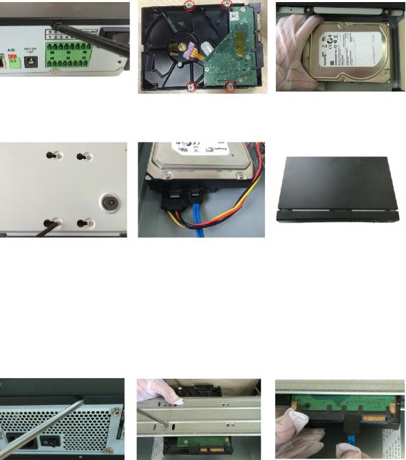
1.Remove the screws to take off the cover.
2.Fix the screws on the HDD but do not fasten them.
3.Match the screws with the holes on the DVR to place the HDD.
4. Turn the DVR upside down |
5. Use the HDD cable and |
6. Put back the cover and |
to see the screws and then |
power cable to connect HDD |
fasten the screws. |
fasten them. |
and mainboard. |
|
Getting Started 4

2.2.2 DH-XVR7104E-4KL-X/DH-XVR7108E-4KL-X/DH-XVR7104E-
4KL-B-X/ DH-XVR7108E-4KL-B-X
2.2.2.1 Installing Battery
The battery is only provided with some models.
1.Put the battery cable through the hole. 2. Connect to the cable into the port.
2.2.2.2Installing HDD
Skip step 6 if the battery is not equipped with the model you purchased.
1.Remove the screws to take off the cover.
4.Match the holes on the bracket with the screw holes on HDD.
2.Remove the screws to take off the bracket.
5.Use screws to fix the HDD onto the bracket.
3.Put the HDD onto the bracket.
6.(Optional) Put the battery cable through the hole to connect into the cable port.
Getting Started 5

7. Use the HDD cable and |
8. Install the bracket back and |
9. Put back the cover and |
power cable to connect |
then fasten the screws. |
fasten the screws. |
HDD and mainboard. |
|
|
2.2.3 DH-XVR4116HS-X/DH-XVR5108HS-X/DH-XVR5116HS-X/DH -XVR5104HS-4KL-X/DH-XVR5108HS-4KL-X/ DH-XVR5108H-X/DH-XVR5116H-X/DH-XVR5104H-4KL-X/DH-XVR 5108H-4KL-X/DH-XVR5116H-4KL-X/DH-XVR5108HE-X/DH-XVR51 16HE-X/DH-XVR7104HE-4KL-X/DH-XVR7108HE-4KL-X/DH-XVR7 116HE-4KL-X/DH-XVR7108HE-4K-X/DH-XVR5104HS-X/ DH-XVR4104HS-X/DH-XVR5104H-X/DH-XVR5104HE-X/DH-XVR4 108HS-X
1.Remove the screws on the rear panel.
4.Turn the device to see the back side of it. Aim the screws of the HDD at the holes on the back of the
2. Fix the screws on the HDD |
3. Place the HDD onto the |
but do not be fastened. |
Device. |
5. Use the HDD cable and |
6. Put back the cover and |
power cable to connect |
fix the screws. |
HDD and mainboard. |
|
Getting Started 6
device and fix the screws.
2.2.4 DH-XVR4216AN-X/DH-XVR4232AN-X/DH-XVR5216AN-X/D H-XVR5232AN-X/DH-XVR5208AN-4KL-X/DH-XVR5216AN-4KL-X/ DH-XVR5216A-X/DH-XVR7208A-4KL-X/DH-XVR7216A-4KL-X/DH- XVR7208A-4K-X
1.Remove the screws on the cover.
4.Turn the device to see the back side of it. Aim the screws of the HDD at the holes on the back of the device, and then fix the screws.
2.Fix the screws onto the HDD, but do not be fastened.
5.Use the HDD cable and power cable to connect HDD and mainboard.
3.Put the HDD into the Device.
6.Put back the cover and fix the screws.
2.2.5 DH-XVR7416L-4KL-X/DH-XVR5432L-X
1.Remove the screws on cover.
2.Use the screws to fix the HDD onto the bracket.
3.Connect one end of HDD cable to the HDD.
Getting Started 7
4. Connect the other end of |
5. Use the power cable to |
6. Put back the cover and fix |
HDD cable to the |
connect HDD and |
the screws. |
mainboard. |
mainboard. |
|
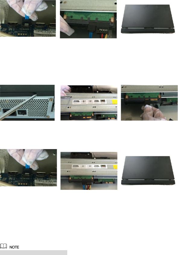
2.2.6 DH-XVR7816S-4KL-X/DH-XVR5832S-X
1.Loose the screws on the panel and remove the cover.
2.Fix the HDD(s) onto the bracket. Remove the top bracket if you want to install HDD to the bottom bracket.
3.Connect one end of HDD cable to the HDD.
4.Connect the other end of HDD cable to the mainboard
5.Use the power cable to connect HDD and mainboard.
6.Put back the cover and fix the screws.
2.3 Installing Device into Rack
Not all models support this function.
To install the DVR into Rack, do the following:
Step 1 Check if the in-house temperature is lower than 35 (95 ) and make sure the 15cm (6in.) spacing around the Device for ventilation.
Step 2 Use six screws to fix the DVR on each side. Step 3 Install from the bottom up.
Getting Started 8
If you want to install more accessories to the rack, take preventive measures to avoid power
socket overload.
Step 4 Install more accessories to the rack if needed.
Getting Started 9
3 The Grand Tour
This chapter introduces various components of the Device, remote control and mouse operations.
3.1 Front Panel
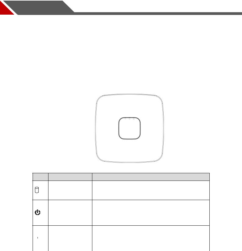
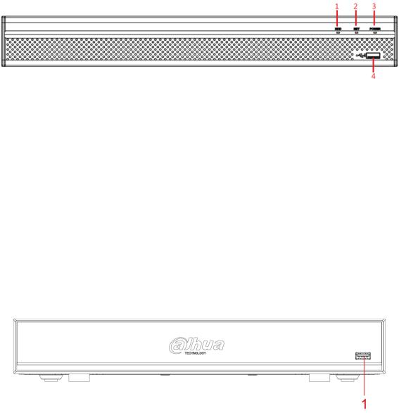
3.1.1 DH-XVR5108C-X/DH-XVR5104C-4KL-X/DH-XVR5104C-X/
DH-XVR4104C-X/DH-XVR4108C-X
Figure 3-1
Icon |
Name |
Function |
The indicator is off when the HDD is running normally.
HDD status indicator The indicator glows blue when the HDD is in malfunction.
The indicator is off when the power is connected
Power status |
abnormally. |
indicator |
The indicator glows blue when the power is connected |
|
normally. |
The indicator is off when the network connection is
|
|
|
|
|
|
Network status |
correct. |
|
|
|
|
||||
|
|
|
|
|
|
indicator |
The indicator glows blue when the network connection |
|
|
|
|
|
|
||
|
|
|
|
|
|
|
is abnormal. |
|
|
|
|
|
|
|
|
|
|
|
|
|
|
|
Table 3-1 |
The Grand Tour 10
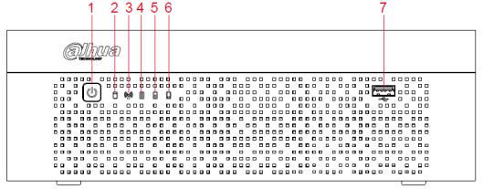
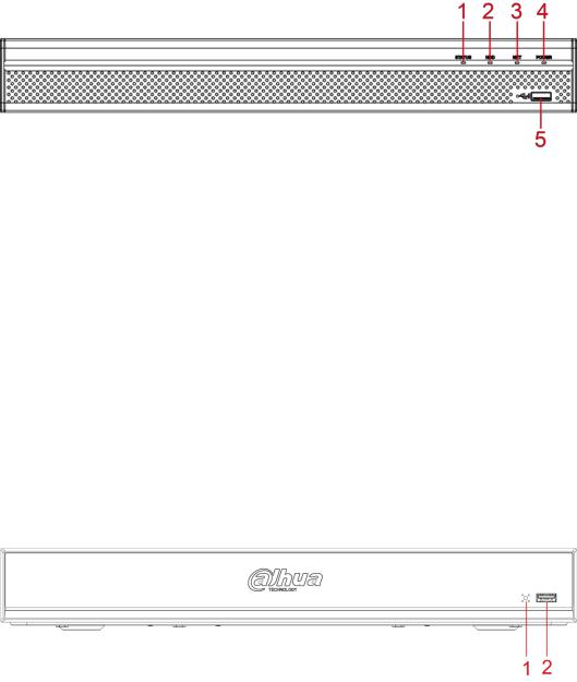
3.1.2 DH-XVR7104E-4KL-X/DH-XVR7108E-4KL-X/DH-XVR7104E-
4KL-B-X/ DH-XVR7108E-4KL-B-X
Figure 3-2
|
No. |
|
|
Button/Icon |
|
|
Function |
|
|
|
|
|
|
|
|||
|
|
|
|
|
|
|
|
|
1 |
|
|
POWER |
|
Turns on/off the DVR. The indicator glows blue when the DVR is |
|||
|
|
|
turned on. |
|||||
|
|
|
|
|
|
|
||
|
|
|
|
|
|
|
||
2 |
|
HDD status |
|
The indicator glows blue when the HDD is in malfunction. |
||||
|
indicator |
|
||||||
|
|
|
|
|
|
|||
|
|
|
|
|
|
|
||
3 |
|
|
Network status |
|
The indicator glows blue when the network connection is |
|||
|
|
indicator |
|
abnormal. |
||||
|
|
|
|
|
||||
|
|
|
|
|
|
|
|
|
|
|
|
|
|
|
|
When the battery remains full or no less than sixty percent, |
|
|
|
|
|
|
|
|
the No.4 indicator is on, and the No.5 and No.6 are out. |
|
|
|
|
|
|
|
|
When the battery remains between thirty percent and sixty |
|
|
|
|
|
Battery status |
|
percent, the No.5 indicator is on and the others are out. |
||
4,5,6 |
|
|
|
When the battery remains between one percent and thirty |
||||
|
|
indicator |
|
|||||
|
|
|
|
|
percent, the No.6 indicator is on and the others are out. |
|||
|
|
|
|
|
|
|
||
|
|
|
|
|
|
|
When the battery is exhausted, the DVR is turned off, or |
|
|
|
|
|
|
|
|
there is no battery attached to the DVR, all the three |
|
|
|
|
|
|
|
|
indicators are out. |
|
|
|
|
|
|
|
|
|
|
7 |
|
|
USB port |
|
Connects to external devices such as USB storage device, |
|||
|
|
|
keyboard and mouse. |
|||||
|
|
|
|
|
|
|
||
|
|
|
|
|
|
|
|
|
|
|
|
|
|
|
|
Table 3-2 |
|
The Grand Tour 11
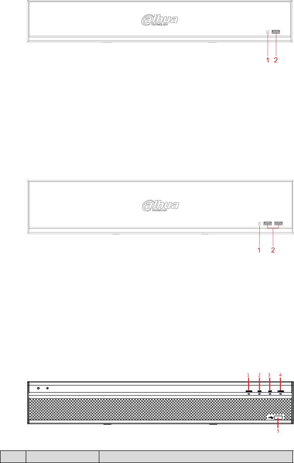
3.1.3 DH-XVR5108H-X/DH-XVR5116H-X/DH-XVR5104H-4KL-X/D H-XVR5108H-4KL-X/DH-XVR5116H-4KL-X/DH-XVR5108HE-X/DH- XVR5116HE-X/DH-XVR4116HS-X/DH-XVR5108HS-X/DH-XVR511 6HS-X/DH-XVR5104HS-4KL-X/DH-XVR5108HS-4KL-X/ DH-XVR5104HS-X/DH-XVR4104HS-X/DH-XVR4108HS-X/DH-XVR 5104H-X/DH-XVR5104HE-X
|
|
|
|
|
|
|
Figure 3-3 |
|
|
|
|
|
|
|
|
|
|
|
No. |
|
|
Port Name |
|
|
Function |
|
|
|
|
|
|
|
|
|
|
1 |
|
|
HDD |
Glows blue when HDD status is abnormal. |
||||
|
|
|
|
|
|
|||
2 |
|
|
NET |
|
Glows blue when network status is abnormal. |
|||
|
|
|
|
|
|
|||
3 |
|
|
POWER |
|
Glows blue when the power is connected properly. |
|||
|
|
|
|
|
|
|
|
|
4 |
|
|
USB port |
|
Connects to peripheral devices such as USB storage device, |
|||
|
|
|
keyboard and mouse. |
|||||
|
|
|
|
|
|
|
||
|
|
|
|
|
|
|
|
|
|
|
|
|
|
|
|
Table 3-3 |
|
3.1.4 DH-XVR7104HE-4KL-X/DH-XVR7108HE-4KL-X/DH-XVR711
6HE-4KL-X/DH-XVR7108HE-4K-X
Figure 3-4
|
No. |
|
|
Port Name |
|
|
Function |
|
|
|
|
|
|
|
|||
1 |
|
|
USB port |
|
Connects |
to peripheral devices such as USB storage device, |
||
|
|
|
keyboard and mouse. |
|||||
|
|
|
|
|
|
|
||
|
|
|
|
|
|
|
|
|
|
|
|
|
|
|
|
|
Table 3-4 |
The Grand Tour 12
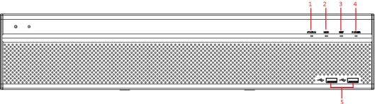
3.1.5 DH-XVR4216AN-X/DH-XVR4232AN-X/DH-XVR5216AN-X/D
H-XVR5232AN-X/DH-XVR5208AN-4KL-X/DH-XVR5216AN-4KL-X/
DH-XVR5216A-X
|
|
|
|
|
|
|
Figure 3-5 |
|
|
|
|
|
|
|
|
|
|
|
No. |
|
|
Port Name |
|
|
Function |
|
|
|
|
|
|
|
|
|
|
1 |
|
|
Status indicator light |
Glows blue when the device is working properly. |
||||
|
|
|
|
|
||||
2 |
|
|
HDD |
Glows blue when HDD status is abnormal. |
||||
|
|
|
|
|
|
|||
3 |
|
|
NET |
|
Glows blue when network status is abnormal. |
|||
|
|
|
|
|
|
|||
4 |
|
|
POWER |
|
Glows blue when the power is connected properly. |
|||
|
|
|
|
|
|
|
|
|
5 |
|
|
USB port |
|
Connects to the external devices such as keyboard, mouse, |
|||
|
|
|
and USB storage device. |
|||||
|
|
|
|
|
|
|
||
|
|
|
|
|
|
|
|
|
|
|
|
|
|
|
|
Table 3-5 |
|
3.1.6 DH-XVR7208A-4KL-X/DH-XVR7216A-4KL-X/DH-XVR7208A-
4K-X
|
|
|
|
|
|
|
Figure 3-6 |
|
|
|
|
|
|
|
|
|
|
|
No. |
|
|
Port Name |
|
|
Function |
|
|
|
|
|
|
|
|
|
|
1 |
|
|
Status indicator light |
Glows blue when the device is working properly. |
||||
|
|
|
|
|
|
|
|
|
2 |
|
|
USB port |
|
Connects to the external devices such as keyboard, mouse, |
|||
|
|
|
and USB storage device. |
|||||
|
|
|
|
|
|
|
||
|
|
|
|
|
|
|
|
|
|
|
|
|
|
|
|
Table 3-6 |
|
The Grand Tour 13
3.1.7 DH-XVR7416L-4KL-X
|
|
|
|
|
|
|
Figure 3-7 |
|
|
|
|
|
|
|
|
|
|
|
No. |
|
|
Port Name |
|
|
Function |
|
|
|
|
|
|
|
|
|
|
1 |
|
|
IR receiver |
Receives infrared signal from remote control. |
||||
|
|
|
|
|
|
|
|
|
2 |
|
|
USB port |
|
Connects to peripheral devices such as USB storage |
|||
|
|
|
device, keyboard and mouse. |
|||||
|
|
|
|
|
|
|
||
|
|
|
|
|
|
|
|
|
|
|
|
|
|
|
|
Table 3-7 |
|
3.1.8 DH-XVR7816S-4KL-X
|
|
|
|
|
|
|
Figure 3-8 |
|
|
|
|
|
|
|
|
|
|
|
No. |
|
|
Port Name |
|
|
Function |
|
|
|
|
|
|
|
|
|
|
1 |
|
|
IR receiver |
Receives infrared signal from remote control. |
||||
|
|
|
|
|
|
|
|
|
2 |
|
|
USB port |
|
Connects to peripheral devices such as USB storage |
|||
|
|
|
device, keyboard and mouse. |
|||||
|
|
|
|
|
|
|
||
|
|
|
|
|
|
|
|
|
|
|
|
|
|
|
|
Table 3-8 |
|
3.1.9 DH-XVR5432L-X
Figure 3-9
No. |
Port Name |
Function |
The Grand Tour 14
|
No. |
|
|
Port Name |
|
|
Function |
|
|
|
|
|
|
|
|||
|
|
|
|
|
|
|
|
|
1 |
|
|
Status indicator light |
Glows blue when the device is working properly. |
||||
|
|
|
|
|
||||
2 |
|
|
HDD |
Glows blue when HDD status is abnormal. |
||||
|
|
|
|
|
|
|||
3 |
|
|
NET |
|
Glows blue when network status is abnormal. |
|||
|
|
|
|
|
|
|||
4 |
|
|
POWER |
|
Glows blue when the power is connected properly. |
|||
|
|
|
|
|
|
|
|
|
5 |
|
|
USB port |
|
Connects to peripheral devices such as USB storage |
|||
|
|
|
device, keyboard and mouse. |
|||||
|
|
|
|
|
|
|
||
|
|
|
|
|
|
|
|
|
|
|
|
|
|
|
|
Table 3-9 |
|
3.1.10 DH-XVR5832S-X
|
|
|
|
|
|
|
Figure 3-10 |
|
|
|
|
|
|
|
|
|
|
|
No. |
|
|
Port Name |
|
|
Function |
|
|
|
|
|
|
|
|
|
|
1 |
|
|
Status indicator light |
Glows blue when the device is working properly. |
||||
|
|
|
|
|
||||
2 |
|
|
HDD |
Glows blue when HDD status is abnormal. |
||||
|
|
|
|
|
|
|||
3 |
|
|
NET |
|
Glows blue when network status is abnormal. |
|||
|
|
|
|
|
|
|||
4 |
|
|
POWER |
|
Glows blue when the power is connected properly. |
|||
|
|
|
|
|
|
|
|
|
5 |
|
|
USB port |
|
Connects to peripheral devices such as USB storage |
|||
|
|
|
device, keyboard and mouse. |
|||||
|
|
|
|
|
|
|
||
|
|
|
|
|
|
|
|
|
|
|
|
|
|
|
|
Table 3-10 |
|
The Grand Tour 15
3.2 Rear Panel
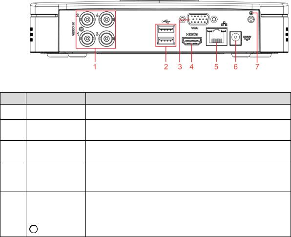
3.2.1 DH-XVR5108C-X/DH-XVR5104C-4KL-X/DH-XVR5104C-X/
DH-XVR4104C-X/DH-XVR4108C-X
|
|
Figure 3-11 |
No. |
Port Name |
Function |
1 |
Video input port |
Connects to analog camera to input video signal. |
2 USB port
Connects to external devices such as USB storage device, keyboard and mouse.
3 VGA port
Outputs analog video data to the connected display with VGA port.
High definition audio and video signal output port.
4 HDMI port The port outputs the uncompressed high definition video and multi-channel audio data to the connected display with HDMI port.
5 |
Network port |
Connects to Ethernet port. |
||||||
|
|
|
|
|
|
|
|
|
6 |
Power input port |
Inputs DC 12V power. |
||||||
|
|
|
|
|
|
|
|
|
7 |
|
|
|
|
|
|
|
Ground terminal. |
|
|
|
|
|
|
|
||
Table 3-11
The Grand Tour 16
3.2.2 DH-XVR7104E-4KL-X/DH-XVR7108E-4KL-X/DH-XVR7104E-
4KL-B-X/ DH-XVR7108E-4KL-B-X
Figure 3-12
|
|
|
|
|
|
|
Figure 3-13 |
|
|
|
|
|
|
|
|
|
|
|
No. |
|
|
Port Name |
|
|
Function |
|
|
|
|
|
|
|
|
|
|
1 |
|
|
Video input port |
|
Connects to analog camera to input video signal. |
|||
|
|
|
|
|
|
|
|
|
2 |
|
|
Audio input port |
|
Receives audio signal output from the devices such as |
|||
|
|
|
microphone. |
|||||
|
|
|
|
|
|
|
||
|
|
|
|
|
|
|||
3 |
|
|
Audio output port |
|
Outputs audio signal to the devices such as the sound box. |
|||
|
|
|
|
|
|
|
||
|
|
|
|
RS485 |
|
Connects to the control devices such as speed dome PTZ. |
||
4 |
|
|
communication |
|
RS485_A port is connected by the cable A and RS485_B is |
|||
|
|
|
|
port |
|
connected to the cable B. |
||
|
|
|
|
|
|
|
|
|
|
|
|
|
|
|
|
High definition audio and video signal output port. |
|
5 |
|
|
HDMI port |
|
The port outputs the uncompressed high definition video and |
|||
|
|
|
multi-channel audio data to the connected display with HDMI |
|||||
|
|
|
|
|
|
|
||
|
|
|
|
|
|
|
port. |
|
|
|
|
|
|
|
|
|
|
6 |
|
|
VGA port |
|
Outputs analog video data to the connected display with VGA |
|||
|
|
|
port. |
|||||
|
|
|
|
|
|
|
||
|
|
|
|
|
|
|
|
|
7, 8 |
|
|
USB port |
|
Connects to external devices such as USB storage device, |
|||
|
|
|
keyboard and mouse. |
|||||
|
|
|
|
|
|
|
||
|
|
|
|
|
|
|||
9 |
|
|
Network port |
|
Connects to Ethernet port. |
|||
|
|
|
|
|
|
|
|
|
The Grand Tour 17
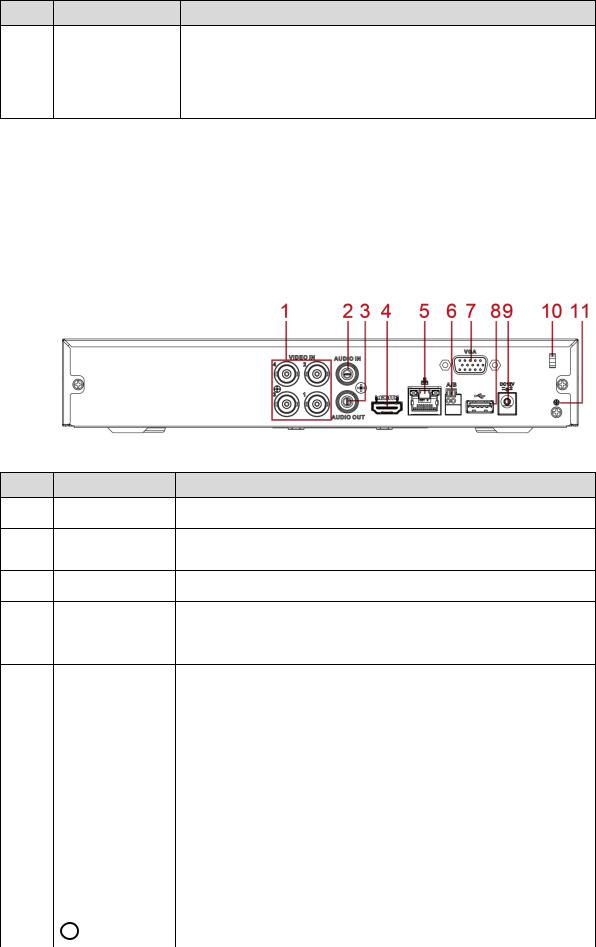
No. |
Port Name |
Function |
10 |
Power input port |
Inputs DC 12V power. |
|
|
|
11 |
Power output port |
Outputs DC 12V power. |
|
|
|
12 |
Ground |
Ground terminal. |
Table 3-12
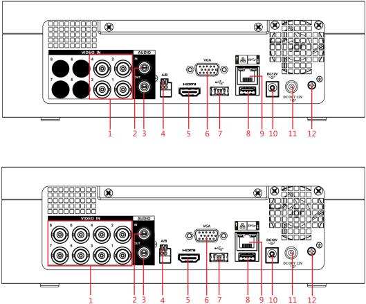
3.2.3 DH-XVR4116HS-X/DH-XVR5108HS-X/DH-XVR5116HS-X/DH -XVR5104HS-4KL-X/DH-XVR5108HS-4KL-X/DH-XVR5104HS-X/ DH-XVR4104HS-X/DH-XVR4108HS-X
|
|
Figure 3-14 |
No. |
Port Name |
Function |
1 |
Video input port |
Connects to analog camera to input video signal. |
2 Audio input port
Receives audio signal output from the devices such as microphone.
3 |
Audio output port Outputs audio signal to the devices such as the sound box. |
High definition audio and video signal output port.
4 HDMI port The port outputs the uncompressed high definition video and multi-channel audio data to the connected display with HDMI port.
5 |
Network port |
Connects to Ethernet port. |
||||||||
|
|
|
|
|
|
|
|
|
|
|
|
RS485 |
Connects to the control devices such as speed dome PTZ. |
||||||||
6 |
communication |
RS485_A port is connected by the cable A and RS485_B is |
||||||||
|
port |
connected to the cable B. |
||||||||
|
|
|
|
|
|
|
|
|
|
|
7 |
VGA port |
Outputs analog video data to the connected display with VGA |
||||||||
port. |
||||||||||
|
|
|
|
|
|
|
|
|
||
|
|
|
|
|
|
|
|
|
|
|
8 |
USB port |
Connects to external devices such as USB storage device, |
||||||||
keyboard and mouse. |
||||||||||
|
|
|
|
|
|
|
|
|
||
|
|
|
|
|
|
|
|
|
|
|
9 |
Power input port |
Inputs DC 12V power. |
||||||||
|
|
|
|
|
|
|
|
|
|
|
10 |
Power cable |
Use clamp to secure the power cable on the DVR in case there is |
||||||||
fastener |
any loss. |
|||||||||
|
||||||||||
|
|
|
|
|
|
|
|
|
|
|
11 |
|
|
|
|
|
|
|
|
Ground terminal. |
|
|
|
|
|
|
|
|
|
|||
|
|
|
|
|
|
|
|
|
|
|
|
|
|
|
|
|
|
|
|
Table 3-13 |
|
The Grand Tour 18
Loading...