


 Loading...
Digital VTH (Version 4.0)
User’s Manual
V1.0.1

Cybersecurity Recommendations
Mandatory actions to be taken towards cybersecurity
1. Change Passwords and Use Strong Passwords:
The number one reason systems get “hacked” is due to having weak or default passwords. It is recommended to change default passwords immediately and choose a strong password whenever possible. A strong password should be made up of at least 8 characters and a combination of special characters, numbers, and upper and lower case letters.
2. Update Firmware
As is standard procedure in the tech-industry, we recommend keeping NVR, DVR, and IP camera firmware up-to-date to ensure the system is current with the latest security patches and fixes.
“Nice to have” recommendations to improve your network security
1. Change Passwords Regularly
Regularly change the credentials to your devices to help ensure that only authorized users are able to access the system.
2. Change Default HTTP and TCP Ports:
● Change default HTTP and TCP ports for systems. These are the two ports used to communicate and to view video feeds remotely.
● These ports can be changed to any set of numbers between 1025-65535. Avoiding the default ports reduces the risk of outsiders being able to guess which ports you are using.
3. Enable HTTPS/SSL:
Set up an SSL Certificate to enable HTTPS. This will encrypt all communication between your devices and recorder.
4. Enable IP Filter:
Enabling your IP filter will prevent everyone, except those with specified IP addresses, from accessing the system.
5. Change ONVIF Password:
On older IP Camera firmware, the ONVIF password does not change when you change the system’s credentials. You will need to either update the camera’s firmware to the latest revision or manually change the ONVIF password.
6. Forward Only Ports You Need:
II
●Only forward the HTTP and TCP ports that you need to use. Do not forward a huge range of numbers to the device. Do not DMZ the device's IP address.
●You do not need to forward any ports for individual cameras if they are all connected to a recorder on site; just the NVR is needed.
7. Disable Auto-Login on SmartPSS:
Those using SmartPSS to view their system and on a computer that is used by multiple people should disable auto-login. This adds a layer of security to prevent users without the appropriate credentials from accessing the system.
8. Use a Different Username and Password for SmartPSS:
In the event that your social media, bank, email, etc. account is compromised, you would not want someone collecting those passwords and trying them out on your video surveillance system. Using a different username and password for your security system will make it more difficult for someone to guess their way into your system.
9. Limit Features of Guest Accounts:
If your system is set up for multiple users, ensure that each user only has rights to features and functions they need to use to perform their job.
10. UPnP:
●UPnP will automatically try to forward ports in your router or modem. Normally this would be a good thing. However, if your system automatically forwards the ports and you leave the credentials defaulted, you may end up with unwanted visitors.
●If you manually forwarded the HTTP and TCP ports in your router/modem, this feature should be turned off regardless. Disabling UPnP is recommended when the function is not used in real applications.
11. SNMP:
Disable SNMP if you are not using it. If you are using SNMP, you should do so only temporarily, for tracing and testing purposes only.
12. Multicast:
Multicast is used to share video streams between two recorders. Currently there are no known issues involving Multicast, but if you are not using this feature, deactivation can enhance your network security.
13. Check the Log:
If you suspect that someone has gained unauthorized access to your system, you can check the system log. The system log will show you which IP addresses were used to login to your system and what was accessed.
14. Physically Lock Down the Device:
III
Ideally, you want to prevent any unauthorized physical access to your system. The best way to achieve this is to install the recorder in a lockbox, locking server rack, or in a room that is behind a lock and key.
15. Connect IP Cameras to the PoE Ports on the Back of an NVR:
Cameras connected to the PoE ports on the back of an NVR are isolated from the outside world and cannot be accessed directly.
16. Isolate NVR and IP Camera Network
The network your NVR and IP camera resides on should not be the same network as your public computer network. This will prevent any visitors or unwanted guests from getting access to the same network the security system needs in order to function properly.
IV

Foreword
General
This document mainly introduces function, structure, network, installation process, debugging process of VTH products matched with Version 4.0 VT UI interface, together with operating instruction and technical parameter of UI interface.
Models
|
Type |
|
Model Series |
|
|
Specific Model |
|
|
|
|
VTH5221 series |
|
|
VTH5221DW, VTH5221D, VTH5221DW-C, VTH5221D-C, |
|
|
|
|
|
|
VTH5221D-CW, VTH5221DW-W, VTH5221DW-CW |
||
|
|
|
|
|
|
|
|
|
|
|
|
|
|
|
|
|
|
|
VTH5241 series |
|
|
VTH5241D, VTH5241DW, VTH5241DW-C, VTH5241D-C, |
|
|
|
|
|
|
VTH5241D-CW, VTH5241DW-W, VTH5241DW-CW |
||
|
|
|
|
|
|
|
|
|
|
|
|
|
|
|
|
|
Digital |
|
|
Type A |
|
|
VTH1510A, VTH1520A, VTH1520AS-H, VTH1510AH, |
|
VTH |
|
VTH15 |
|
|
VTH1520AH, VTH1520AS |
|
|
|
|
|
|
|||
|
|
|
|
|
|
|
|
|
|
|
series |
Type B |
|
|
VTH1550B, VTH1560B(W) |
|
|
|
|
|
|
|
|
|
|
|
|
Type CH |
|
|
VTH1510CH, VTH1520CH, VTH1550CH |
|
|
|
|
|
|
|
|
|
|
|
VTH16 series |
|
|
VTH1660CH |
|
|
|
|
|
|
|
|
|
|
|
|
VTH2X series |
|
|
VTH2221A |
|
|
|
|
|
|
|
|
|
|
2-wire VTH |
|
|
|
|
VTH5222H |
|
|
|
|
|
|
|
|
|
Device Upgrade
Please don’t cut off power supply during upgrade. Power can be cut only after the device completes upgrade and reboots.
Safety Instructions
The following categorized signal words with defined meaning might appear in the Manual.
Signal Words |
Meaning |
|
Indicates a high potential hazard which, if not avoided, will result |
|
in death or serious injury. |
|
|
|
Indicates a medium or low potential hazard which, if not avoided, |
|
could result in slight or moderate injury. |
|
|
|
Indicates a potential risk which, if not avoided, could result in |
|
property damage, data loss, lower performance, or unpredictable |
|
result. |
|
|
|
Provides methods to help you solve a problem or save you time. |
|
|
V

Provides additional information as the emphasis and supplement to the text.
Revision History
No. |
Version |
Revision Content |
Release Date |
1 |
V1.0.0 |
First release |
2017.11.1 |
|
|
|
|
2 |
V1.0.1 |
Add privacy protection notice |
2018.05.23 |
|
|
|
|
Privacy Protection Notice
As the device user or data controller, you might collect personal data of others' such as face, fingerprints, car plate number, Email address, phone number, GPS and so on. You need to be in compliance with the local privacy protection laws and regulations to protect the legitimate rights and interests of other people by implementing measures include but not limited to: providing clear and visible identification to inform data subject the existence of surveillance area and providing related contact.
About the Manual
The Manual is for reference only. If there is inconsistency between the Manual and the actual product, the actual product shall prevail.
We are not liable for any loss caused by the operations that do not comply with the Manual.
The Manual would be updated according to the latest laws and regulations of related regions. For detailed information, see the paper User's Manual, CD-ROM, QR code or our official website. If there is inconsistency between paper User's Manual and the electronic version, the electronic version shall prevail.
All the designs and software are subject to change without prior written notice. The product updates might cause some differences between the actual product and the Manual. Please contact the customer service for the latest program and supplementary documentation.
There still might be deviation in technical data, functions and operations description, or errors in print. If there is any doubt or dispute, please refer to our final explanation.
Upgrade the reader software or try other mainstream reader software if the Guide (in PDF format) cannot be opened.
All trademarks, registered trademarks and the company names in the Manual are the properties of their respective owners.
Please visit our website, contact the supplier or customer service if there is any problem occurred when using the device.
If there is any uncertainty or controversy, please refer to our final explanation.
VI

Important Safeguards and Warnings
The following description is the correct application method of the device. Please read the manual carefully before use, in order to prevent danger and property loss. Strictly conform to the manual during application and keep it properly after reading.
Operating Requirement
Please modify the default password after deployment, to avoid being stolen.
Please don’t place and install the device in an area exposed to direct sunlight or near heat generating device.
Please don’t install the device in a humid, dusty or fuliginous area.
Please keep its horizontal installation, or install it at stable places, and prevent it from falling.
Please don’t drip or splash liquids onto the device; don’t put on the device anything filled with liquids, in order to prevent liquids from flowing into the device.
Please install the device at well-ventilated places; don’t block its ventilation opening.
Use the device only within rated input and output range.
Please don’t dismantle the device arbitrarily.
Power Requirement
The product shall use electric wires (power wires) recommended by this area, which shall be used within its rated specification.
Please use power supply that meets SELV (safety extra low voltage) requirements, and supply power with rated voltage that conforms to Limited Power Source in IEC60950-1. For specific power supply requirements, please refer to device labels.
If power plug or appliance coupler is a disconnecting device, during normal use, please keep an angle that facilitates operation.
VII

|
|
|
Table of Contents |
|
|
|
|
|
Cybersecurity Recommendations................................................................................................................. |
II |
|
|
Foreword.............................................................................................................................................................. |
V |
|
|
Important Safeguards and Warnings......................................................................................................... |
VII |
|
1 |
Product Overview ........................................................................................................................................... |
1 |
|
|
1.1 |
Product Profile........................................................................................................................................... |
1 |
|
1.2 |
Product Function ....................................................................................................................................... |
1 |
2 |
Product Structure ........................................................................................................................................... |
3 |
|
|
2.1 |
Front Panel ................................................................................................................................................ |
3 |
|
|
2.1.1 VTH5221 Series /VTH5241 Series............................................................................................. |
3 |
|
|
2.1.2 VTH15 Series Type A/B ............................................................................................................... |
4 |
|
|
2.1.3 VTH15 Series Type CH/5222H ................................................................................................... |
6 |
|
|
2.1.4 VTH1660CH................................................................................................................................... |
7 |
|
|
2.1.5 VTH2221A...................................................................................................................................... |
7 |
|
2.2 |
Rear Panel Port......................................................................................................................................... |
9 |
|
|
2.2.1 VTH5221 Series/VTH5241 Series.............................................................................................. |
9 |
|
|
2.2.2 VTH15 Series Type A/ Type B/ Type CH ................................................................................... |
9 |
|
|
2.2.3 VTH5222CH/VTH1550CHW-2.................................................................................................. |
10 |
|
|
2.2.4 VTH1660CH.................................................................................................................................. |
11 |
|
|
2.2.5 VTH2221A.................................................................................................................................... |
12 |
3 |
Network Diagram .......................................................................................................................................... |
14 |
|
|
3.1 |
2-wire System.......................................................................................................................................... |
14 |
|
3.2 |
Digital System.......................................................................................................................................... |
15 |
4 Device Installation ........................................................................................................................................... |
17 |
||
|
4.1 |
Installation Flow Chart............................................................................................................................ |
17 |
|
4.2 |
Open-case Inspection ............................................................................................................................ |
17 |
|
4.3 |
Installation Requirement ........................................................................................................................ |
18 |
|
4.4 |
Device Installation................................................................................................................................... |
18 |
|
|
4.4.1 Surface Installation ..................................................................................................................... |
18 |
|
|
4.4.2 Installation with 86 Box............................................................................................................... |
19 |
5 |
Device Debugging ........................................................................................................................................ |
20 |
|
|
5.1 |
Debugging Settings ................................................................................................................................ |
20 |
|
|
5.1.1 VTO Settings................................................................................................................................ |
20 |
|
|
5.1.2 VTH Config................................................................................................................................... |
25 |
|
5.2 |
Debugging Verification ........................................................................................................................... |
30 |
|
|
5.2.1 VTO Calls VTH ............................................................................................................................ |
30 |
|
|
5.2.2 VTH Monitors VTO...................................................................................................................... |
30 |
6 |
Interface Operation....................................................................................................................................... |
32 |
|
|
6.1 |
Main Interface.......................................................................................................................................... |
32 |
|
6.2 |
Setting....................................................................................................................................................... |
33 |
|
|
6.2.1 Ring Settings................................................................................................................................ |
33 |
|
|
6.2.2 DND Settings ............................................................................................................................... |
37 |
VIII
6.2.3 Alarm Setting................................................................................................................................ |
38 |
6.2.4 Mode Setting................................................................................................................................ |
42 |
6.2.5 General Setting............................................................................................................................ |
43 |
6.2.6 Product Info.................................................................................................................................. |
49 |
6.3 Project Settings ....................................................................................................................................... |
50 |
6.3.1 Forget Password ......................................................................................................................... |
50 |
6.3.2 Network Settings ......................................................................................................................... |
51 |
6.3.3 VTH Config................................................................................................................................... |
54 |
6.3.4 VTO Config .................................................................................................................................. |
55 |
6.3.5 Search Device ............................................................................................................................. |
56 |
6.3.6 Default........................................................................................................................................... |
58 |
6.3.7 Reset MSG................................................................................................................................... |
59 |
6.4 Call ............................................................................................................................................................ |
59 |
6.4.1 Contact ......................................................................................................................................... |
59 |
6.4.2 Call User....................................................................................................................................... |
61 |
6.4.3 Call from User.............................................................................................................................. |
63 |
6.4.4 Call from VTO .............................................................................................................................. |
64 |
6.4.5 Call Log......................................................................................................................................... |
66 |
6.5 Monitor...................................................................................................................................................... |
66 |
6.5.1 Monitoring of VTO ....................................................................................................................... |
67 |
6.5.2 Monitoring of IPC ........................................................................................................................ |
69 |
6.5.3 Favorite......................................................................................................................................... |
72 |
6.6 SOS........................................................................................................................................................... |
72 |
6.7 Info ............................................................................................................................................................ |
73 |
6.7.1 Alarm ............................................................................................................................................. |
73 |
6.7.2 Guest Message ........................................................................................................................... |
74 |
6.7.3 Publish Info .................................................................................................................................. |
75 |
6.7.4 Video Pic ...................................................................................................................................... |
76 |
6.8 Unlock Function....................................................................................................................................... |
76 |
6.9 Arm and Disarm Function ...................................................................................................................... |
76 |
6.9.1 Arm ................................................................................................................................................ |
76 |
6.9.2 Disarm........................................................................................................................................... |
77 |
Appendix 1 Technical Parameters........................................................................................................................ |
79 |
Appendix 1.1 VTH5221D Series /VTH5241D Series .............................................................................. |
79 |
Appendix 1.2 VTH5222H Series................................................................................................................. |
79 |
Appendix 1.3 VTH15 Series Type A/B/CH ................................................................................................ |
80 |
Appendix 1.4 VTH16 Series ........................................................................................................................ |
81 |
Appendix 1.5 VTH2221A Series ................................................................................................................. |
81 |
IX

1 Product Overview
1.1 Product Profile
VTH series product is a digital video intercom home station for numerous homes, integrating monitoring, intercom and unlocking. With embedded technology, all IP network, SNMP (Simple Network Management Protocol) network management technology and network encryption technology, achieve more stable system operation, richer functional extension, more convenient system management and safer data transmission.
1.2 Product Function
Wi-Fi Networking
Realize Wi-Fi networking of devices.
Video Intercom
Call or connect VTO and VTH; realize talk.
Monitoring
Monitor fence station, VTO and IPC devices.
SOS
Press the key to call the Call Center in case of an emergency.
Auto Snapshot
Snapshot the call picture or monitoring picture, and store them in SD card or FTP.
DND (Do Not Disturb)
Avoid other’s incoming call interference.
Remote Unlock
Realize remote unlock.
1
Arm and Disarm
Provide 6/8-channel area setting, arm and disarm them.
Playback
Play back videos and pictures in SD card of this device.
Alarm
After 8/6-channel area triggers an alarm, pop up an alarm prompt interface, provide linkage alarm output and report to Call Center.
Record Inquiry
Inquire call records and alarm records.
Message Inquiry
Inquire guests’ message, videos, pictures and announcements issued by Property
Management Center.
2

2 Product Structure
2.1 Front Panel
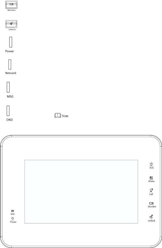
2.1.1 VTH5221 Series /VTH5241 Series
VTH5221D is a 7″ digital indoor monitor, and VTH5241D is a 10″ digital indoor monitor. Their front panels have the same size, as shown in Figure 2-1. Please refer to Table 2-1 for details.
|
|
|
|
|
Figure 2-1 |
|
|
|
|
|
|
|
|
No. |
|
Name |
|
|
Description |
|
1 |
|
Camera |
|
|
|
|
|
|
occlusion |
|
|
Slide it to occlude or open the camera. |
|
|
|
switch |
|
|
|
|
|
|
|
|
|
|
|
2 |
|
Camera |
|
|
Only VTH5221DW-C and VTH5241DW-C support front-facing |
|
|
|
|
|
camera. |
|
|
|
|
|
|
|
|
|
|
|
|
|
|
|
|
3 |
|
Microphone |
|
|
Voice input. |
|
|
|
|
|
|
|
|
4 |
|
Display screen |
|
|
7″ type D digital VTH owns a 7″ high-definition LCD. |
|
|
|
|
|
10″ type D digital VTH owns a 10″ high-definition LCD. |
|
|
|
|
|
|
|
|
3

No. |
|
Name |
|
|
Description |
|
5 |
|
Unlock |
|
|
Press this key during calling, talking, monitoring and speaking of |
|
|
|
|
|
VTO, so corresponding VTO will be unlocked. |
|
|
|
|
|
|
|
|
|
|
|
|
|
|
|
|
6 |
|
Monitor |
|
|
In standby mode, press this key to monitor the main VTO. |
|
|
|
|
|
During monitoring, press this key to exit monitoring. |
|
|
|
|
|
|
|
|
|
7 |
|
Menu |
|
|
Press this key to return to main menu. |
|
|
|
|
|
|
|
|
8 |
|
|
|
|
In case of incoming call, press this key to answer the call. |
|
|
|
|
|
|
During talk, press this key to hang up. |
|
|
|
Call |
|
|
During monitoring, press this key to speak to unit VTO, villa |
|
|
|
|
|
|
VTO and fence station. |
|
|
|
|
|
|
During speaking, press this key to exit speaking. |
|
9 |
|
SOS |
|
|
Press this key to call the Call Center in case of emergency. |
|
|
|
|
|
|
|
|
|
|
|
|
|
Table 2-1 |
|
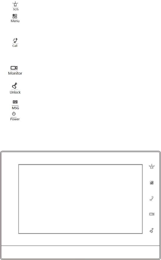
2.1.2 VTH15 Series Type A/B
In VTH15 series, different types of devices have different front panels.
|
|
|
Figure 2-2 VTH15 Series Type A |
|
||
|
|
|
|
|
|
|
Icon |
|
Name |
|
|
Description |
|
|
|
SOS |
|
|
Press this key to call the Call Center in case of |
|
|
|
|
|
emergency. |
|
|
|
|
|
|
|
|
|
|
|
|
|
|
|
|
|
|
Menu |
|
|
Press this key to return to main menu. |
|
|
|
|
|
|
|
|
|
|
|
|
|
In case of incoming call, press this key to answer |
|
|
|
Call |
|
|
the call. |
|
|
|
|
|
|
During talk, press this key to hang up. |
|
4
Icon |
Name |
|
Description |
|
|
|
|
During monitoring, press this key to speak to |
|
|
|
|
apartment VTO, villa VTO and fence station. |
|
|
|
|
During speaking, press this key to exit speaking. |
|
|
|
|
In standby mode, press this key to monitor the |
|
|
Monitor |
|
main VTO. |
|
|
|
|
During monitoring, press this key to exit monitoring. |
|
|
|
|
Press this key during calling, talking, monitoring and |
|
|
Unlock |
|
speaking of VTO, so corresponding VTO will be |
|
|
|
|
unlocked. |
|
|
|
|
|
|
|
Power |
|
If this indicator turns on in green, it represents normal |
|
|
indicator |
|
power supply. |
|
|
|
|
|
|
|
|
|
If this indicator turns on, it represents normal |
|
|
Network |
|
communication with VTO. |
|
|
indicator |
|
If this indicator turns off, it represents abnormal |
|
|
|
|
communication with VTO. |
|
|
|
|
|
|
|
Message |
|
If this indicator turns on, it represents that there are |
|
|
indicator |
|
unread messages. |
|
|
|
|
|
|
|
|
|
If this indicator turns on in green, it represents that DND |
|
|
DND |
|
function is enabled. |
|
|
indicator |
|
|
|
|
|
|
|
|
|
|
|
For DND settings, please refer to “6.2.2 DND Settings”. |
|
|
|
|
|
|
|
|
|
Table 2-2 |
|
Figure 2-3 VTH15 Series Type B
5
Icon |
|
Name |
|
|
Description |
|
|
SOS |
|
|
Press this key to call the Call Center in case of |
|
|
|
|
emergency. |
|
|
|
|
|
|
|
|
|
|
|
|
|
|
|
Menu |
|
|
Press this key to return to main menu. |
|
|
|
|
|
|
|
|
|
|
|
In case of incoming call, press this key to answer |
|
|
|
|
|
the call. |
|
|
Call |
|
|
During talk, press this key to hang up. |
|
|
|
|
During monitoring, press this key to speak to |
|
|
|
|
|
|
|
|
|
|
|
|
apartment VTO, villa VTO and fence station. |
|
|
|
|
|
During speaking, press this key to exit speaking. |
|
|
|
|
|
In standby mode, press this key to monitor the |
|
|
Monitor |
|
|
main VTO. |
|
|
|
|
|
During monitoring, press this key to exit monitoring. |
|
|
|
|
|
Press this key during calling, talking, monitoring and |
|
|
Unlock |
|
|
speaking of VTO, so corresponding VTO will be |
|
|
|
|
|
unlocked. |
|
|
|
|
|
|
|
|
Message |
|
|
If this indicator turns on, it represents that there are |
|
|
indicator |
|
|
unread messages. |
|
|
|
|
|
|
|
|
Power |
|
|
If this indicator turns on in green, it represents normal |
|
|
indicator |
|
|
power supply. |
|
|
|
|
|
|
|
|
|
|
|
Table 2-3 |
2.1.3 VTH15 Series Type CH/5222H
Figure 2-4
6

Icon |
|
Name |
|
|
Description |
|
|
|
SOS |
|
|
Press this key to call the Call Center in case of emergency. |
|
|
|
|
|
|
|
|
|
|
Menu |
|
|
Press this key to return to main menu. |
|
|
|
|
|
|
|
|
|
|
|
|
|
In case of incoming call, press this key to answer the |
|
|
|
|
|
|
call. |
|
|
|
Call |
|
|
During talk, press this key to hang up. |
|
|
|
|
|
During monitoring, press this key to speak to apartment |
|
|
|
|
|
|
|
|
|
|
|
|
|
|
VTO, villa VTO and fence station. |
|
|
|
|
|
|
During speaking, press this key to exit speaking. |
|
|
|
|
|
|
In standby mode, press this key to monitor the main |
|
|
|
Monitor |
|
|
VTO. |
|
|
|
|
|
|
During monitoring, press this key to exit monitoring. |
|
|
|
Unlock |
|
|
Press this key during calling, talking, monitoring and |
|
|
|
|
|
speaking of VTO, so corresponding VTO will be unlocked. |
|
|
|
|
|
|
|
|
|
|
|
|
|
|
|
|
|
|
|
|
|
Table 2-4 |
|
2.1.4 VTH1660CH
|
|
|
|
Figure 2-5 |
||
|
|
|
|
|
|
|
No. |
|
|
Name |
|
|
Description |
1 |
|
|
Power indicator |
|
|
If this indicator turns on in green, it represents |
|
|
|
|
normal power supply. |
||
|
|
|
|
|
|
|
|
|
|
|
|
|
|
2 |
|
|
Microphone |
|
|
Audio input. |
|
|
|
|
|
|
|
|
|
|
|
Table 2-5 |
||
2.1.5 VTH2221A
7

|
|
|
|
|
Figure 2-6 |
|
|
|
|
|
|
Icon |
|
Name |
|
|
Description |
|
|
SOS |
|
|
Press this key to call the Call Center in case of |
|
|
|
|
emergency. |
|
|
|
|
|
|
|
|
|
|
|
|
|
|
|
Menu |
|
|
Press this key to return to main menu. |
|
|
|
|
|
|
|
|
|
|
|
In case of incoming call, press this key to answer |
|
|
|
|
|
the call. |
|
|
Call |
|
|
During talk, press this key to hang up. |
|
|
|
|
During monitoring, press this key to speak to |
|
|
|
|
|
|
|
|
|
|
|
|
apartment VTO, villa VTO and fence station. |
|
|
|
|
|
During speaking, press this key to exit speaking. |
|
|
|
|
|
In standby mode, press this key to monitor the |
|
|
Monitor |
|
|
main VTO. |
|
|
|
|
|
During monitoring, press this key to exit monitoring. |
|
|
|
|
|
Press this key during calling, talking, monitoring and |
|
|
Unlock |
|
|
speaking of VTO, so corresponding VTO will be |
|
|
|
|
|
unlocked. |
|
|
|
|
|
|
|
|
Power |
|
|
If this indicator turns on in green, it represents normal |
|
|
indicator |
|
|
power supply. |
|
|
|
|
|
|
|
|
Message |
|
|
If this indicator turns on, it represents that there are |
|
|
indicator |
|
|
unread messages. |
|
|
|
|
|
|
|
|
|
|
|
Table 2-6 |
8

2.2 Rear Panel Port
2.2.1 VTH5221 Series/VTH5241 Series
Port positions are slightly different on the rear panel of VTH5221 series and VTH5241 series, but the same port owns the same function. Taking VTH5221 as an example, specific functions of ports are introduced, as shown in Figure 2-7.
Figure 2-7
2.2.2 VTH15 Series Type A/ Type B/ Type CH
In VTH15 series, different types of digital VTH have different port positions, but the same port owns the same function. Taking VTH1550CH as an example, specific functions of ports are introduced, as shown in Figure 2-8.
9
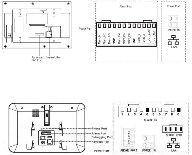
Figure 2-8
In VTH type A/type B series, different types of digital VTH have different port positions, but the same port provides the same function. Taking VTH1560B as an example, specific functions of ports are introduced, as shown in Figure 2-9.
Figure 2-9
2.2.3 VTH5222CH/VTH1550CHW-2
VTH5222CH 2-wire VTH provides 6 alarm input ports, 1 alarm output port, 1 RS485 port and 1 group of 2-wire port, as shown in Figure 2-10. VTH1550CHW-2 has 3 groups of 2-wire port.
10

Figure 2-10
2.2.4 VTH1660CH
VTH1660CH digital VTH provides 8 alarm input ports, 1 RS485 port, 1 debugging port, 1 network port and power port, as shown in Figure 2-11.
11
Figure 2-11
2.2.5 VTH2221A
VTH2221A digital VTH provides 8 alarm input ports, 1 network port and power port, as shown in Figure 2-12.
12
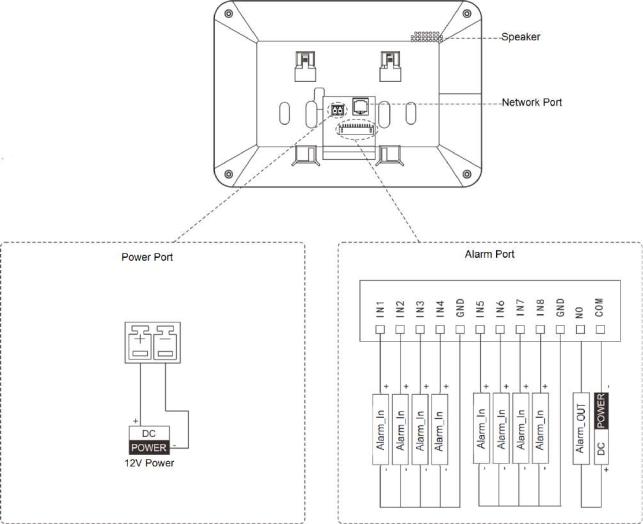
Figure 2-12
13

3 Network Diagram
3.1 2-wire System
Network diagram of 2-wire system is shown in Figure 3-1.
Figure 3-1
14
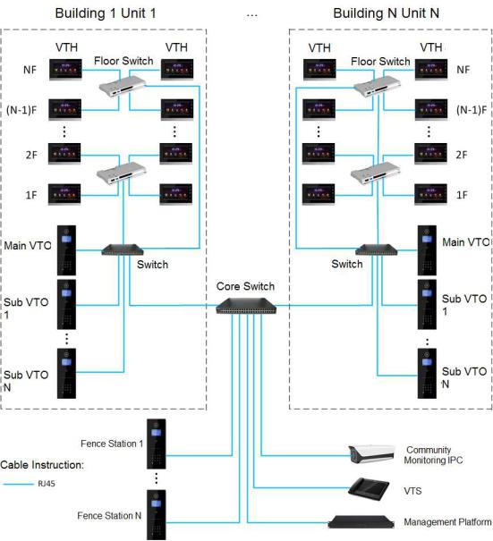
3.2 Digital System
Digital system network consist of two types:
VTH adopts PoE power supply from floor switch, as shown in Figure 3-2.
Figure 3-2
VTH adopts independent power supply from power supply device, as shown in Figure 3-3.
15
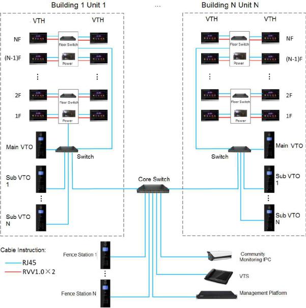
Figure 3-3
16

4 Device Installation
4.1 Installation Flow Chart
VTH installation flow chart is shown in Figure 4-1 Please install VTH in the following steps.
Figure 4-1
For cable connection, please refer to “2.2 Rear Panel Port”.
For device installation, please refer to “4.4 Device Installation”.
4.2Open-case Inspection
Please carry out open-case inspection when receiving the device. Please timely contact our
17

after-sales service personnel in case of any problems.
Sequence |
|
|
Item |
|
|
|
|
Content |
|
|
|
|
|
|
|
|
|
Appearance |
|
|
Inspect whether there are obvious damages. |
|
|||||
|
|
|
|
|
|
|
|
|
|
|
|
|
|
1 |
|
|
Overall |
Package |
|
|
|
Inspect |
whether |
there are |
accidental |
|
|
|
|
package |
|
|
|
impacts. |
|
|
|
|
|
||
|
|
|
|
|
|
|
|
|
|
|
|
||
|
|
|
|
|
|
|
|
|
|
|
|||
|
|
|
|
Fittings |
|
|
|
Inspect whether fittings are complete. |
|
||||
|
|
|
|
|
|
|
|
|
|
|
|
|
|
|
|
|
|
Device model |
|
|
Inspect |
whether it |
is consistent |
with order |
|
||
|
|
|
|
|
|
contract. |
|
|
|
|
|||
|
|
|
|
|
|
|
|
|
|
|
|
||
|
|
|
|
|
|
|
|
|
|
||||
|
|
|
|
|
|
|
|
Inspect whether it is torn or damaged. |
|
||||
2 |
|
|
Model |
|
|
|
|
|
|
|
|
|
|
|
|
|
|
|
|
|
|
|
|
|
|
||
|
|
and label |
Label |
on |
the |
|
|
|
|
|
|
|
|
|
|
|
Don’t tear or discard the label, otherwise |
|
|||||||||
|
|
|
|
|
|||||||||
|
|
|
|
device |
|
|
|
|
|
|
|||
|
|
|
|
|
|
|
warranty service won’t be provided. When |
|
|||||
|
|
|
|
|
|
|
|
|
|
|
|||
|
|
|
|
|
|
|
|
dialing our after-sales hotline, please provide |
|
||||
|
|
|
|
|
|
|
|
|
|
|
|||
|
|
|
|
|
|
|
|
serial number of the product. |
|
|
|
||
|
|
|
|
|
|
|
|
|
|||||
3 |
|
|
Device |
Appearance |
|
|
Inspect whether there are obvious damages. |
|
|||||
|
|
|
|
|
|
|
|
|
|
|
|
|
|
|
|
|
|
|
Table 4-1 |
|
|
|
|
|
|
||
4.3Installation Requirement
Don’t install VTH in bad environment, such as condensation, high temperature, stained, dusty, chemically corrosive and direct sunshine environment.
Engineering installation and debugging shall be done by professional teams. Please don’t dismantle or repair arbitrarily in case of device failure.
4.4Device Installation
It is suggested that installation height of device central point shall be 1.4cm 1.6cm above the ground.
4.4.1 Surface Installation
Directly install the device with a bracket onto a wall, which is suitable for all types of devices.
Take “VTH1550CH” for example.
Step 1 Drill holes in the wall according to hole positions of the bracket. Step 2 Fix installation bracket directly onto the wall with screws.
Step 3 Put the device into installation bracket from top down.
18
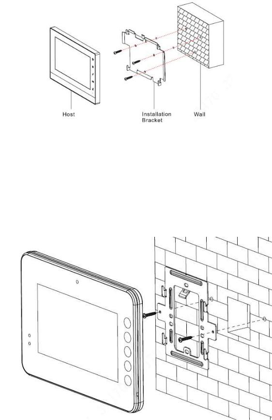
Figure 4-2
4.4.2 Installation with 86 Box
Install the device with 86 box, which is suitable for all types of devices. Take “1560B/BW” for example.
Step 1 Embed 86 box into a wall at a proper height. Step 2 Fix installation bracket onto 86 box with screws.
Step 3 Put the device into installation bracket from top down.
Figure 4-3
19
Loading...