

Page 1
GOULDS PUMPS
Installation, Operation
and
Maintenance Instruction
Volute Casing Pumps
Model:
ICP
ICPI
ICPH
ICPIH
Page 2

IMPORTANT SAFETY NOTICE
To: Our Valued Customers
User safety is a major focus in the design of our products. Following the precautions outlined in this
manual will minimize your risk of injury.
ITT Goulds pumps will provide safe, trouble-free service when properly installed, maintained, and
operated.
Safe installation, operation, and maintenance of ITT Goulds Pumps equipment are an essential end user
responsibility. This Pump Safety Manual identifies specific safety risks that must be considered at all
times during product life. Understanding and adhering to these safety warnings is mandatory to ensure
personnel, property, and/or the environment will not be harmed. Adherence to these warnings alone,
however, is not sufficient — it is anticipated that the end user will also comply with industry and corporate
safety standards. Identifying and eliminating unsafe installation, operating and maintenance practices is
the responsibility of all individuals involved in the installation, operation, and maintenance of industrial
equipment.
Please take the time to review and understand the safe installation, operation, and maintenance guidelines
outlined in this Pump Safety Manual and the Instruction, Operation, and Maintenance (IOM) manual.
Current manuals are available at
your nearest Goulds Pumps sales representative.
www.gouldspumps.com/literature_ioms.html or by contacting
These manuals must be read and understood before installation and star t-up.
For additional information, contact your nearest Goulds Pumps sales representative or visit our Web site at
www.gouldspumps.com.
S-1
Page 3
SAFETY WARNINGS
Specific to pumping equipment, significant risks bear reinforcement above and beyond normal safety precautions.
WARNING
A pump is a pressure vessel with rotating parts that can be hazard o us. An y press ure vessel can explode,
rupture, or discharge its contents if sufficiently ove r press u r i zed causi n g deat h, personal injury, property
damage, and/or damage to the environment. All necessary measures must be taken to ensure over
pressurization does not occur.
WARNING
Operation of any pumping system with a blocked suction and discharge must be avoided in all cases.
Operation, even for a brief period under these conditions, can cause superheating of enclosed pumpage and
result in a violent explosion. All necessary measures must be taken by the end user to ensure this condition is
avoided.
WARNING
The pump may handle hazardous and/or toxic fluids. Care must be taken to identify the contents of the pump
and eliminate the possibility of exposure, particularly if hazardous and/or toxic. Potential hazards include, but
are not limited to, high temperature, flammable, acidic, caustic, explosive, and other risks.
WARNING
Pumping equipment Instruction, Operation, and Maintenance manuals clearly identify accepted methods for
disassembling pumping units. These methods must be adhered to. Specifically, applying heat to impellers
and/or impeller retaining devices to aid in their removal is strictly forbidden. Trapped liquid can rapidly
expand and result in a violent explosion and injury.
ITT Goulds Pumps will not accept responsibility for physical injury, damage, or delays caused by a failure to
observe the instructions for installation, operation, and maintenance contained in this Pump Safety Manual or the
current IOM available at www.gouldspumps.com/literature.
S-2
Page 4
SAFETY
DEFINITIONS
Throughout this manual the words WARNING, CAUTION, ELECTRICAL, and ATEX are used to indicate
where special operator attention is required.
Observe all Cautions and Warnings highlighted in this Pump Safety Manual and the IOM provided with
your equipment.
WARNING
Indicates a hazardous situation which, if not avoided, could result in death or serious injury.
Example:
Pump shall never be operated without coupling guard installed correctly.
CAUTION
Indicates a hazardous situation which, if not avoi ded, could result in minor or moderate injury.
Example: Throttling flow from the suction side may cause cavitation and pump damage.
ELECTRICAL HAZARD
Indicates the possibility of electrical risks if directions are not followed.
Example: Lock out driver power to prevent electric shock, accidental start-up, and physical injury.
When installed in potentially explosive atmospheres, the instructions that follow the Ex symbol must be
followed. Personal injury and/or equipment damage may occur if these instructions are not followed. If there
is any question regarding these requirements or if the equipment is to be modified, please contact an ITT
Goulds Pumps representative before proceeding.
Example:
parts, resulting in a spark and heat generation.
Improper impeller adjustment could cause contact between the rotating and stationary
S-3
Page 5
GENERAL PRECAUTIONS
WARNING
A pump is a pressure vessel with rotating parts that can be hazardous. Hazardous fluids may be contained by the
pump including high temperature, flammable, acidic, caustic, explosive, and other risks. Operators and
maintenance personnel must realize this and follow safety measures. Personal injuries will result if procedures
outlined in this manual are not followed. ITT Goulds Pumps will not accept responsibility for physical injury,
damage or delays caused by a failure to observe the instructions in this manual and the IOM provided with your
equipment.
WARNING
WARNING
General Precautions
NEVER use heat to disassemble pump due to risk of explosion from tapped liquid.
NEVER APPLY HEAT TO REMOVE IMPELLER. It may explode due to
trapped liquid.
WARNING
WARNING
WARNING
WARNING
WARNING
WARNING
WARNING
WARNING
WARNING
NEVER operate pump without safety devices installed.
NEVER operate pump without coupling guard correctly installed.
NEVER run pump below recommended minimum flow when dry, or without
prime.
ALWAYS lock out power to the driver befo re per fo rming pump maintenance.
NEVER operate pump with discharge valve closed.
NEVER operate pump with suction valve closed.
DO NOT change service application without approval of an authorized ITT
Goulds Pumps representative.
Safety Apparel:
Insulated work gloves when handling hot bearings or using bearing heater
Heavy work gloves when handling parts with shar p ed ges, especially
impellers
Safety glasses (with side shields) for eye protection
Steel-toed shoes for foot protection when handling parts, heavy tools, etc.
Other personal protective equipment to protect against hazardous/toxic fluids
Receiving:
Assembled pumping units and their components are heavy. Failure to properly lift
and support equipment can result in serious physical injury and/or equipment
damage. Lift equipment only at specifically identified lifting points or as
instructed in the current IOM. Current manuals are available at
www.gouldspumps.com/literature_ioms.html or from your local ITT Goulds
Pumps sales representative. Note: Lifting devices (eyebolts, slings, spreaders, etc.)
must be rated, selected, and used for the entire load being lifted.
Alignment:
WARNING
Shaft alignment procedures must be followed to prevent catastrophic failure of
drive components or unintended contact of rotating parts. Follow coupling
manufacturer’s coupling installation and operation procedures.
S-4
Page 6

WARNING
CAUTION
General Precautions
Before beginning any alignment procedure, make sure driver power is locked out.
Failure to lock out driver power will result in serious physical injury.
Piping:
Never draw piping into place by forcing at the flan ged con necti on s of t he pump.
This may impose dangerous strains on the unit and cause misalignment between
pump and driver. Pipe strain will adversely effect the operation of the pump
resulting in physical injury and damage to the equipment.
WARNING
WARNING
WARNING
WARNING
WARNING
WARNING
WARNING
WARNING
WARNING
WARNING
WARNING
CAUTION
CAUTION
WARNING
Flanged Connections:
Use only fasteners of the proper size and material.
Replace all corroded fasteners.
Ensure all fasteners are properly tightened and there are no missing fasteners.
Startup and Operation:
When installing in a potentially explosive environment, please ensure that the
motor is properly certified.
Operating pump in reverse rotation may result in contact of metal parts, heat
generation, and breach of containment.
Lock out driver power to prevent accidental start-up and physical injury.
The impeller clearance setting procedure must be followed. Improperly setting
the clearance or not following any of the proper procedures can result in sparks,
unexpected heat generation and equipment damage.
If using a cartridge mechanical seal, the centering clips must be installed and set
screws loosened prior to setting impeller clearance. Failure to do so could result
in sparks, heat generation, and mechanical seal damage.
The coupling used in an ATEX classified environment must be properly certified
and must be constructed from a non-sparking material.
Never operate a pump without coupling guard properly installed. Personal injury
will occur if pump is run without coupling guard.
Make sure to properly lubricate the bearings. Failure to do so may result in excess
heat generation, sparks, and / or premature failure.
The mechanical seal used in an ATEX classified environment must be properly
certified. Prior to start up, ensure all points of potential leakage of process fluid to
the work environment are closed.
Never operate the pump without liquid supplied to mechanical seal. Running a
mechanical seal dry, even for a few seconds, can cause seal damage and must be
avoided. Physical injury can occur if mechanical seal fails.
Never attempt to replace packing until the driver is properly locked out and the
coupling spacer is removed.
WARNING
WARNING
S-5
Dynamic seals are not allowed in an ATEX classified environment.
DO NOT operate pump below minimum rated flows or with suction and/or
discharge valve closed. These conditions may create an explosive hazard due to
vaporization of pumpage and can quickly lead to pump failure and physical injury.
Page 7
WARNING
WARNING
WARNING
WARNING
WARNING
CAUTION
CAUTION
WARNING
CAUTION
CAUTION
General Precautions
Ensure pump is isolated from system and pressure is relieved before
disassembling pump, removing plu gs, ope ni n g vent or drain valves, or
disconnecting piping.
Shutdown, Disassembly, and Reassembly:
Pump components can be heavy. Proper methods of lifting must be employed to
avoid physical injury and/or equipment damage. Steel toed shoes must be worn at
all times.
The pump may handle hazardous and/or toxic fluids. Observe proper
decontamination procedures. Proper personal protective equipment should be
worn. Precautions must be taken to prevent physical injury. Pumpage must be
handled and disposed of in conformance with applicable environmental
regulations.
Operator must be aware of pumpage and safety precautions to prevent physical
injury.
Lock out driver power to prevent accidental startup and physical injury.
Allow all system and pump components to cool before handling them to prevent
physical injury.
If pump is a Model NM3171, NM3196, 3198, 3298, V3298, SP3298, 4150, 4550,
or 3107, there may be a risk of static electric discharge from plastic parts that are
not properly grounded. If pumped fluid is non-conductive, pump should be
drained and flushed with a conductive fluid under conditions that will not allow
for a spark to be released to the atmosphere.
Never apply heat to remove an impeller. The use of heat may cause an explosion
due to trapped fluid, resulting in severe physical injury and property damage.
Wear heavy work gloves when handling impellers as sharp edges may cause
physical injury.
Wear insulated gloves when using a bearing heater. Bearings will get hot and can
cause physical injury.
S-6
Page 8
ATEX CONSIDERATIONS and INTENDED USE
Special care must be taken in potentially explosive environments to ensure that the equipment is properly
maintained. This includes but is not limited to:
1. Monitoring the pump frame and liquid end temperature.
2. Maintaining proper bearing lubrication.
3. Ensuring that the pump is operated in the intended hydraulic range.
The ATEX conformance is only applicable when the pump unit is operated within its intended use. Operating,
installing or maintaining the pump unit in any way that is not covered in the Instruction, Operation, and
Maintenance manual (IOM) can cause serious personal injury or damage to the equipment. This includes any
modification to the equipment or use of parts not provided by ITT Goulds Pumps. If there is any question
regarding the intended use of the equipment, please contact an ITT Goulds represe ntative before proceeding.
Current IOMs are available at
Pumps Sales representative.
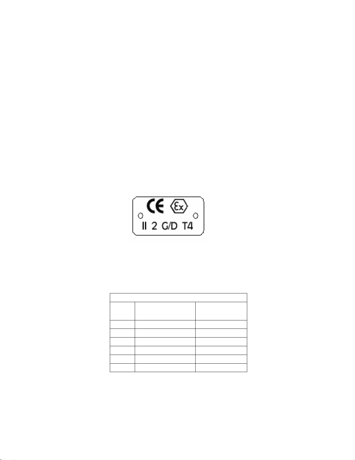
All pumping unit (pump, seal, coupling, motor and pump accessories) certified for use in an ATEX classified
environment, are identified by an ATEX tag secured to the pump or the baseplate on which it is mounted. A
typical tag would look like this:
www.gouldspumps.com/literature_ioms.html or from your local ITT Goulds
The CE and the Ex designate the ATEX compliance. The code directly below these symbols reads as follows:
II = Group 2
2 = Category 2
G/D = Gas and Dust present
T4 = Temperature class, can be T1 to T6 (see Table 1)
Table 1
Max permissible
surface temperature
Code
T1 842 (450) 700 (372)
T2 572 (300) 530 (277)
T3 392 (200) 350 (177)
T4 275 (135) 235 (113)
T5 212 (100) Option not available
T6 185 (85) Option not available
o
F (oC)
The code classification marked on the equipment must be in accordance with the specified area where the
equipment will be installed. If it is not, do not operate the equipment and contact your ITT Goulds Pumps sales
representative before proceeding.
Max permissible
liquid temperature
o
F (oC)
S-7
Page 9
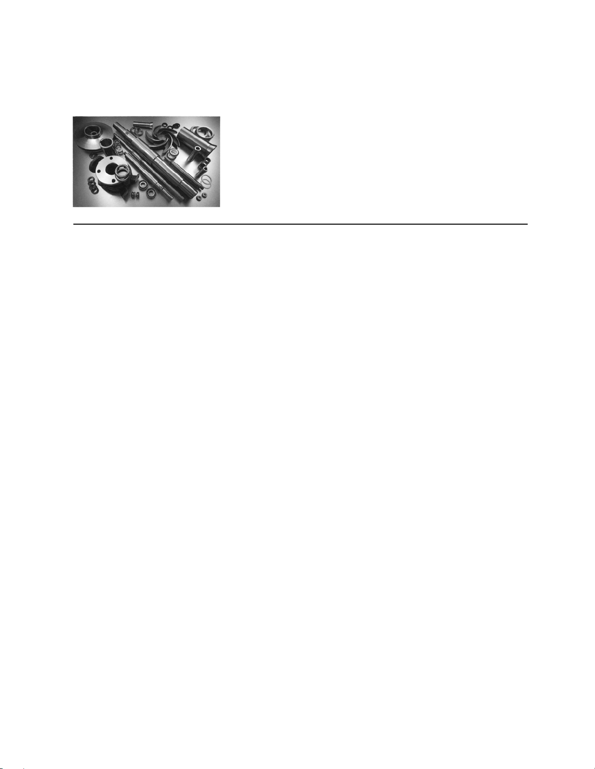
PARTS
The use of genuine Goulds parts will provide the safest and
most reliable operation of your pump. ITT Goulds Pumps ISO
certification and quality control procedures ensure the parts are
manufactured to the highest quality and safety levels.
Please contact your local Goulds representative for details on
genuine Goulds parts.
S-8
Page 10

Installation, Operating and Maintenance Instruction
TABLE of CONTENTS
Pump Name Plate .....................................................2
ATEX-Label (only for pumps in compliance with
EC directive 94/9/EC)................................................ 2
1. General ..................................................................3
1.1 Guarantee.........................................................3
2. Safety Regulations ............................................... 3
2.1 Marking of References in the Operating
Instructions..............................................................3
2.2 Dangers of non-observance of the Safety
Instructions..............................................................4
2.3 Safety Instructions for the Operator / Worker...4
2.4 Safety Instructions for Maintenance, Inspections
and Mounting Work.................................................4
2.5 Unauthorized Alteration and Spare Parts
Production............................................................... 4
2.6 Undue Operation............................................... 4
2.7 Explosion Protection......................................... 4
2.8 Use acc. to Regulations.................................... 6
3. Description............................................................ 6
3.1 Design............................................................... 6
3.2 Shaft Sealing..................................................... 6
3.3 Bearings............................................................ 7
3.4 Approximate Value for Sound Pressure Level.. 7
3.5 Permitted Nozzle Loads and Torques at the
Pump Nozzles ........................................................ 7
4. Transport, Handling, Storage.............................. 8
4.1 Transport, Handling ..........................................8
4.2 Storage / Conservation.....................................9
5. Mounting / Installation ......................................... 9
5.1 Mounting of Pump / Unit ...................................9
5.2 Connection of Pipings to the Pump ................10
5.3 Coupling.......................................................... 10
ICP 100-English page 1
Article No 24264412
5.4 Drive................................................................12
5.5 Electric Connection .........................................12
5.6 Final Control....................................................12
6. Start-up, Operation, Shut down.........................12
6.1 Initial start-up...................................................12
6.2 Switch on drive................................................12
6.3 Restarting........................................................13
6.4 Limits of Operation ..........................................13
6.5 Lubrication of Bearings....................................13
6.6 Monitoring........................................................14
6.7 Shutting down..................................................14
6.8 Storage / longer periods of non-operation.......14
7. Servicing, Maintenance......................................15
7.1 General remarks..............................................15
7.2 Mechanical seals.............................................15
7.3 Stuffing boxes..................................................15
7.4 Lubrication and Change of Lubricant..............15
7.5 Coupling ..........................................................15
7.6 Cleaning of pump ............................................16
8. Dismantling and repair of pump........................16
8.1 General remarks..............................................16
8.2 General............................................................16
8.3 Disassembly of Back Pull Out Assembly ........16
8.4 Removal of Impeller ........................................17
8.5 Removal of Shaft Sealing................................17
8.6 Removal of Bearing.........................................17
8.7 Reconditioning.................................................18
8.8 Mounting..........................................................18
9. Recommended Spare Parts, Spare Pumps......19
9.1 Spare Parts......................................................19
9.2 Stand-by pumps ..............................................20
10. Faults - Causes and Solutions.........................20
Model ICP
Revision 00
Issue 05/2006
Page 11

Installation, Operating and Maintenance Instruction
Pump Name Plate
Model ICP
TYPE *) Type and size of pump
S/N *) Serial number
YEAR Year of construction
Q Rated capacity at the operating point
P Rated power at the operating point
H Head (Energy head) at the operating point
N Speed
P
Max. permitted casing-operation-pressure
all w C
(=highest discharge pressure at the rated
operating temperature to which the pump
casing can be used).
TEMP Rated operating temperature of pumped
liquid
ITEM NO Customer equipment number
*) All details of design and materials are defined with
this information. They must be stated on all inquiries
to the manufacturer resp. orders of spare.
MATL Material of construction
ATEX-Label (only for pumps in compliance with EC directive 94/9/EC)
CE Marking of compliance with the EC directive
94/9/EC
Ex specific marking for explosion protection
II Symbol for the appliance group
2G Symbol for the category (2), explosive atmos-
phere due to gases, vapors or mist (G)
c Symbol for used ignition protection (construc-
tual safety "c")
T1-T. Symbol for classification of the theoretically
available range of the temperature classes -
data for temperature class refer to chapter
2.7.5; Data for maximum permitted tempera-
ture of pumped liquid refer to pump name
plate, data sheet and / or order confirmation.
ICP 100-English page 2
Article No 24264412
The conformity with the EC directive 94/9/EC "
Equipment and Protective Systems for Use in Potentially Explosive Atmospheres " is declared by the issue of the EC-Declaration of Conformity and the attachment of the ATEX-label at the pump (bearing
bracket). The ATEX-label is attached additionally to
the pump name plate.
Revision 00
Issue 05/2006
Page 12

Installation, Operating and Maintenance Instruction
1. General
Model ICP
This product corresponds with the requirements of the
Machine directive 98/37/EG (former 89/392/EWG).
The staff employed on installation, operation,
inspection and maintenance must be able to
prove that they know about the relevant accident prevention regulations and that they are
suitably qualified for this work. If the staff does
not have the relevant knowledge, they should
be provided with suitable instruction.
The operation safety of the delivered pump resp. unit
(= pump with motor) can only be guaranteed on designated use according to the attached data sheet and
/ or order confirmation resp. chapter 6 "Start-up, Operation, Shut down".
The operator is responsible for following the instructions and complying with the safety requirements
given in these Operating Instructions.
Smooth operation of the pump or pump unit can only
be achieved if installation and maintenance are carried out carefully in accordance with the rules generally applied in the field of engineering and electrical
engineering.
If not all the information can be found in these Operating Instructions, please contact us.
The manufacturer takes no responsibility for the pump
or pump unit if the Operating Instructions are not followed.
These Operating Instructions should be kept in a safe
place for future use.
If this pump or pump unit is handed on to any third
party, it is essential that these Operating Instructions
and the operating conditions and working limits given
in the Confirmation of Order are also passed on in full.
These Operating Instructions do not take into account
all design details and variants nor all the possible
chance occurrences and events which might happen
during installation, operation and maintenance.
We retain all copyright in these Operating Instructions;
they are intended only for personal use by the owner
of the pump or the pump unit. The Operating Instructions contain technical instructions and drawings
which may not, as a whole or in part, be reproduced,
distributed or used in any unauthorised way for competitive purposes or passed on to others.
1.1 Guarantee
The guarantee is given in accordance with our Conditions of Delivery and/or the confirmation of order.
Repair work during the guarantee period may only be
carried out by us, or subject to our written approval.
Otherwise the guarantee ceases to apply.
Longer-term guarantees basically only cover correct
handling and use of the specified material. The guarantee shall not cover natural wear and tear and all
parts subject to wear, such as impellers, shaft sealings, shafts, shaft sleeves, bearings, wear rings etc.
or damage caused by transport or improper handling.
In order for the guarantee to apply, it is essential that
the pump or pump unit is used in accordance with the
operating conditions given on the name plate, confirmation of order and in the data sheet. This applies
particularly for the endurance of the materials and
smooth running of the pump and shaft sealing.
If one or more aspects of the actual operating conditions are different, we should be asked to confirm in
writing that the pump is suitable.
2. Safety Regulations
These Operating Instructions contain important instructions which must be followed when the pump is
assembled and commissioned and during operating
and maintenance. For this reason, these Operating
Instructions must be read by the skilled staff responsible and/or by the operator of the plant before it is
installed and commissioned, and they must be left
permanently available at the place where the pump or
pump unit is in use.
These Operating Instructions do not refer to the
General Regulations on Accident Prevention or
local safety and/or operating regulations. The operator is responsible for complying with these (if
necessary by calling in additional installation
staff).
Equally, instructions and safety devices regarding
handling and disposal of the pumped media and/or
auxilliary media for flushing, lubrication a.s.o., especially if they are explosive, toxical, hot a.s.o., are not
part of this operating instruction.
ICP 100-English page 3
Article No 24264412
For the competent and prescribed handling only the
operator is responsible.
2.1 Marking of References in the Operating Instructions
The safety regulations contained in these Operating
Instructions are specially marked with safety signs acc.
to nach DIN 4844:
Safety reference!
Non-observance can impair the pump and its
function.
EC-Ex Marking
Products intended for use in explosive atmospheres must be marked.
General Symbol for Danger!
Persons can be endangered.
Warning of electric voltage!
Revision 00
Issue 05/2006
Page 13

Installation, Operating and Maintenance Instruction
f
Safety instructions attached directly to the pump resp.
unit must be followed under any circumstances. Further they must be kept in good readable condition.
In the same way, as these Operating Instructions
of the pump, all possibly attached Operating Instructions of accessories (e.g. motor) must be
noticed and kept available.
2.2 Dangers of non-observance of the
Safety Instructions
Non-observance of the Safety Instructions can
lead to loss of any claim for damages.
Further, non-observance can lead to following risks:
Failure of important functions of the machine or
facility.
Failure of electronic appliances and measuring
instruments by magnetic fields.
Endangering of persons and their personal prop-
erty by magnetic fields.
Endangering of persons by electric, mechanic and
chemical influences.
Endangering of environment through leakage of
dangerous substances.
On application of the unit in areas endangered
to explosion special attention must be paid to
sections marked with Ex.
2.3 Safety Instructions for the Operator /
Worker
Depending on the operating conditions, wear and
tear, corrosion or age will limit the working life of
the pump/pump unit, and its specified characteristics. The operator must ensure that regular inspection and maintenance are carried out so that
all parts are replaced in good time, which would
otherwise endanger the safe operation of the system. If abnormal operation or any damage are observed, the pump must cease operation immediately.
If the breakdown or failure of any system or unit
could lead to people being hurt or property being
damaged, such system or unit must be provided
with alarm devices and/or spare modules, and
they should be tested regularly to ensure that they
function properly.
If there is any risk of injury from hot or cold ma-
chine parts, these parts must be protected against
contact by the user, or suitable warning signs
must be affixed.
Contact protection on moving parts (e.g. coupling
guards) must not be removed from systems that
are in operation.
If the sound level of a pump or pump unit is above
85 dB(A) an ear protection has to be used when
staying near the pump for some time.
If dangerous media (e.g. explosive, toxic, hot)
leak out (e.g. from shaft seals), these must be directed away so that there is no danger to people
or the environment. The provisions of the law
must be observed.
ICP 100-English page 4
Article No 24264412
Measures should be taken to exclude any danger
from electricity (e.g. by complying with the local
regulations on electrical equipment). If work is
carried out on live electrical components, they
should be unplugged from the mains or the main
switch turned off and fuse unscrewed. A motor
protection switch is to be provided.
Model ICP
2.4 Safety Instructions for Maintenance,
Inspections and Mounting Work
The operator is responsible that any maintenance,
inspections and mounting work is made by authorized competent personnel, which must be informed by havingng read the Operating Instructions.
Basically, all work on the pump or pump unit
should only be carried out when the pump is stationary and not under pressure. All parts must be
allowed to return to ambient temperature. Make
sure that no-one can start the motor during such
work. It is essential that the procedure for stopping the system described in the Operating Instructions is observed. Pumps or pump systems
that carry media that are dangerous to health
must be decontaminated before being taken apart.
Safety Data Sheets for the various liquids handled.
Immediately after finishing work, all safety and
protective devices must be replaced or restarted.
2.5 Unauthorized Alteration and Spare
Parts Production
Alteration or changes of the machine are permitted
after agreement with the manufacturer.
Original spare parts and accessory authorized by the
manufacturer are serving the safety.
The use of other parts can lead to loss of liability for
therefrom resulting consequences.
2.6 Undue Operation
The operating safety of the delivered machine can
only be guaranteed by designated use acc. to the
following chapters of the Operating Instructions. The
limits stated in the data sheet and / or order confirmation must not be exceeded under any circumstances.
2.7 Explosion Protection
On application of units in areas endangered to explosion measures and references in the chapters 2.7.1 to
2.7.6 must be observed, so that explosion protection
is guaranteed.
2.7.1 Filling of unit
During operation of the pump the system of the
suction and pressure pipe and the pump itsel
must permanently be filled with the pumped
liquid. Thus, no explosive atmosphere can develop and the danger of dry-run is avoided.
Revision 00
Issue 05/2006
Page 14

Installation, Operating and Maintenance Instruction
f
f
r
f
r
If the operator can´t guarantee that, according
monitoring measures must be provided.
Equally all seal casings, auxiliary systems o
the shaft sealing, as well as heating and cooling
systems must be filled carefully.
2.7.2 Marking
The marking of the pump refers to the pump
itself. For coupling and motor resp. further additions a separate Declaration of Conformity, as
well as a corresponding marking must be available.
Example of of marking at pump:
CE Ex II 2 G c T... .
The marking shows the theoretically applicable range
of temperature classes. The different temperatures,
permitted acc. to pump design, result as shown in
chapter 2.7.5. The same is valid for the drive.
For a whole unit (pump, coupling, motor) with different
temperature classes the lowest is valid.
2.7.3 Rotation Control
Carry out rotation control with speparated coupling halves only! Refer to chapter 5.5 and 6.1
as well.
If danger of explosion is also existing during
installation, the rotation control must not be
carried out by short start-up of the empty pump,
to avoid undue temperature increase in case o
contact of rotating and stationary parts.
2.7.4 Operation of pump
The pump must only be started up with fully opened
suction side and slightly opened pressure side valve.
The start-up against closed non-return valve, however,
is possible. Immediately after the start-up the discharge side valve must be adjusted to the operating
point.
Refer to chapter 6.2, as well.
Operation with closed valve in suction and / or
discharge pipe is not permitted!
There´s a danger, that high surface temperatures are developing at the pump casing afte
relatively short time, through fast heating of the
liquid inside the pump.
Fast pressure increase inside the pump can
lead to overload and, thus, the pump can burst.
In chapter 6.4.1 the minimum flow is stated. Longer
operating phases with these flows and the named
liquids don´t cause additional increase of surface
temperature at the pump.
Furthermore the references in chapter 6 of these operating Instructions must be taken into consideration.
ICP 100-English page 5
Article No 24264412
Model ICP
On pumps with mech. seals the permitted temperature limits can be exceeded due to dry-run.
Dry run not only can occur on insufficiently
filled seal casing, but also because of too much
gas in the medium.
Operation of the pump out of the permitted operating range can lead to dry-run, as well.
2.7.5 Temperature Limits
Under normal operating conditions the highest
temperatures must be expected at the surface
of the pump casing and in the area of the bearings.
The surface temperature occurring at pump casing
corresponds with the temperature of the pumped liquid.
If the pump is heated (e. g. heating jacket), care
must be taken, that the temperature classes,
prescribed for the plant are observed.
In the area of the bearing bracket free contact from
surface to surrounding must be given.
During operation of the pump it must be secured that an overabundant sedimentation o
dust is avoided (regular cleaning), to prevent
heating of pump surface over the permitted
temperature.
The operator of the plant must secure that the
defined operating temperature is observed. The
max. allowed temperature of the pumped liquid at
suction depends on the particular temperature
class.
The following table shows the theoretical temperature
limits of the pumped liquid in consideration of the
temperature classes acc. to EN 13463-1.
Temperature class acc.
EN 13463-1
Temperature limit of
pumped liquid
T4 (135°C) 135°C
T3 (200°C) 180°C
T2 (300°C) 260°C
T1 (450°C) 260°C
The particular allowed operating temperature of
the pump is shown in the data sheet and / o
the order confirmation resp. the type plate at
the pump.
In the area of the bearings the temperature class T4 is
guaranteed, provided that the ambient temperature is
40°C and the appliance is duly operated and maintained.
2.7.6 Maintenance
For a secure and reliable operation it must be
secured by regular inspections, that the unit is
maintained competently and is kept in good
technical condition.
Revision 00
Issue 05/2006
Page 15

Installation, Operating and Maintenance Instruction
Example: Function of bearings. Operation and application conditions are essentially responsible for their
achievable life cycle.
By regular control of the lubricant and the running
sound the danger of occurring over temperatures by
bearings running hot or defect bearing seals is
avoided. Refer to chapter 6.6 and 7.4.
The function of the shaft sealing must be secured by
regular control.
If auxiliary systems (e.g. external flushing, cooling,
heating) are installiert, it must be checked, if monitoring devices are necessary to secure the function.
2.7.7 Electric switches and control device, Instrumentation and accessories
Electric switches and control devices, instrumentation and accessories like e.g. flush tanks,
a.s.o., must correspond with the valid safety
requirements and regulations for explosion
protection.
2.8 Use acc. to Regulations
2.8.1 Speed, Pressure, Temperature
Suitable safety measures must be taken at the
plant to ensure that the speed, pressure and
temperature of the pump and the shaft sealing
do not exceed the limit values given in the data
sheet and / or order confirmation. The given
admission pressures (system pressures) must
also be sufficiently high.
Further, pressure shocks, as can occur on too fast
shut down of the facility, must be kept away from the
pump (e.g. by non-return valve at pressure side, fly
wheel, airtanks). Quick temperature changes must be
avoided. They could cause a temperature shock and
lead to damage or impair the function of single components.
2.8.2 Permitted Nozzle Loads and Torques
Model ICP
Basically the suction and discharge piping must
be designed in such way, that as little forces as
possible are effective to the pump. If that is not
possible, the values shown in chapter 3.5 must
not be exceeded under any circumstances.
This is valid for the operation as well as for the
standstill of the pump and therefore for all possible pressures and temperatures of the unit.
2.8.3 NPSH
The pumped liquid must have a min. pressure
NPSH at the impeller inlet, so that cavitation
free work is secured resp. a "break off" of the
pump flow is prevented. This condition is fulfilled, when NPSH-value of the system
(NPSHA) lies above NPSH-value of the pump
(NPSHR) under all operating conditions.
Attentention must especially be piad to the NPSHvalue on pumping liquids near the vapour pressure. If
the NPSH-value of the pump remains under, this can
lead from damage of the material due to cavitation to
destruction by overheating.
The NPSH-value of the pump (NPSHR) is shown in
the curves of every pump type.
2.8.4 Sealing, Flushing, Cooling
Suitable provisions for the regulation and monitoring
of sealing, flushing or cooling are to be provided.
When handling dangerous liquids or if temperatures
are high, care should be taken to ensure that the
pump ceases operating if the sealing, flushing or cooling system fails.
Sealing, flushing and cooling systems must always be
operational before the pump is started up. They
should not be taken out of operation until the pump
has stopped, provided that the nature of the operation
allows this at all.
2.8.5 Back Flow
In systems where pumps are operating in closed circuits under pressure (gas cushions, steam pressure),
the pressure of the gas cushion must not be reduced
via the pump, since the back flow speed may be much
higher than the operating speed, which would destroy
the unit.
3. Description
3.1 Design
ICP-pumps are single-stage volute casing pumps in
process design. Hydraulic design and dimensions
comply with ISO 2858/ EN 22858, the technical design complies with ISO 5199/EN 25199. For pump
pressure up to 25 bar and volute casing with centerline feet.
ICPI-pumps as design ICP, except that they have an
inducer.
ICPH- and ICPIH-pumps pumps additionally possess
a cooling or heating of the casing cover and/or the
volute casing.
ICP 100-English page 6
Article No 24264412
The pumps are designed as modular systems and
can, therefore, be delivered in many variants (e.g.
different materials, shaft sealings, different kinds of
lubrication, cooling / heating, a.s.o.).
The permitted application conditions and design details of the delivered pump are shown in the attached
data sheet and / or order confirmation.
3.2 Shaft Sealing
Basically there are two kinds of shaft sealing: the
paccking and the mechanical seal, whereas, there
again are many variants of both kinds. At the data
Revision 00
Issue 05/2006
Page 16

Installation, Operating and Maintenance Instruction
f
f
sheet and / or the order confirmation the shaft sealing
type of your pump is shown.
An instruction for the packing of a stuffing box resp.
for the mounting and operation of mech. seals can be
found in the appendix of the particular "Mounting Instructions of the Shaft Sealing".
In areas endangered to explosion the use o
pumps with packings is forbidden!
Further details about packings and mech.
seals, as well as the therewith connected accidental dangers, you can find in chapter 6.6 and
in chapters 7.2 and 7.3.
3.3 Bearings
The pump shaft is guided by antifriction bearings. In
the data sheet and / or order confirmation you can see,
if your pump is designed for oil lubrication (standard
design) or grease lubrication (special design).
In areas endangered to explosion the use o
pumps with grease lubricated bearings is forbidden!
3.3.1 Used bearings
The size of the bearing bracket of your pump is shown
in the data sheet and / or order confirmation.
Bearing bracket
24 6307 - C3 3307A - C3
32 6309 - C3 3309A - C3
42 6311 - C3 3311A - C3
48 6313 - C3 3313A - C3
pump side drive side
Bearing type
3.3.2 Oil Sump Cooling
On temperatures of the pumped liquid over 160°C an
oil sump cooling is required.
For connection refer to list "Connections" in the annex.
For cooling use pure, non-aggressive water with a
maximum incomming temperature of 30°C.
Cooling water should be hand-warm at discharge.
The pressure in the cooling system must not ex-
ceed max. 6 bar.
Provide control devices for temperature and pres-
sure monitoring.
3.4 Approximate Value for Sound Pressure Level
Nominal
power
PN
in kW
0,55 50,5 49,5 49,0 58,0 52,0 51,5
0,75 52,0 51,0 50,5 59,0 54,0 53,0
1,1 54,0 53,0 52,5 60,0 55,5 54,5
1,5 55,5 55,0 54,5 63,5 57,0 56,0
2,2 58,0 57,0 56,5 64,5 59,0 58,5
3,0 59,5 58,5 58,0 68,5 61,0 62,0
4,0 61,0 60,0 59,5 69,0 63,0 63,0
5,5 63,0 62,0 61,5 70,0 65,0 65,0
7,5 64,5 63,5 63,0 70,5 67,0 67,0
11,0 66,5 65,5 65,0 72,0 69,0 68,5
15,0 68,0 67,0 66,5 72,5 70,0 70,5
2950
min-1
ICP 100-English page 7
Article No 24264412
Sound pressure level LpA in dB(A)
Pump alone Pump + Motor
1450
min-1
975
min-1
2950
min-1
1450
min
-1
975
min
-1
18,5 69,0 68,5 68,0 73,0 70,5 74,0
22,0 70,5 69,5 69,0 74,5 71,0 74,0
30,0 72,0 71,0 70,5 75,0 72,0 73,0
37,0 73,0 72,0 71,5 76,0 73,5 73,5
45,0 74,0 73,0 72,5 77,0 74,5 73,5
55,0 75,5 74,5 74,0 78,0 75,5 75,0
75,0 77,0 76,0 75,5 80,0 76,5 76,0
90,0 78,0 77,0 -- 80,5 77,5 -110,0 79,0 78,0 -- 82,5 78,5 -132,0 80,0 79,0 -- 83,0 79,5 -160,0 81,0 80,0 -- 83,5 80,5 --
Model ICP
Sound pressure level LpA measured in 1 m distance
from pump surface acc. to DIN 45635, part 1 and 24.
Room and foundation influences are not considered.
The tolerance for these values is ±3 dB(A).
Addition with 60 Hz-operation:
Pump alone: −
Pump with motor: +4 dB(A)
3.5 Permitted Nozzle Loads and Torques
at the Pump Nozzles ...
... following the Europump-Recommendation for
pump acc. to ISO 5199.
The data for forces and torques are only valid for
static piping loads.
The values given in the chart are valid for pump units
with standard-ICP-base frames (ungrouted).
All values for forces and torques refer to standard
materials EN-GJS400-18LT and 1.4408.
pic 1
Revision 00
Issue 05/2006
Page 17

Installation, Operating and Maintenance Instruction
Model ICP
Sizes
40-25-160 40 1250 1100 1000 1950 1300 900 1050 1900 25 750 700 850 1300 900 600 700 1300
40-25-200 40 1250 1100 1000 1950 1300 900 1050 1900 25 750 700 850 1300 900 600 700 1300
40-25-250 40 1250 1100 1000 1950 1300 900 1050 1900 25 750 700 850 1300 900 600 700 1300
50-32-160 50 1650 1500 1350 2600 1400 1000 1150 2050 32 900 850 1050 1650 1100 750 850 1600
50-32-200 50 1650 1500 1350 2600 1400 1000 1150 2050 32 900 850 1050 1650 1100 750 850 1600
50-32-250 50 1650 1500 1350 2600 1400 1000 1150 2050 32 900 850 1050 1650 1100 750 850 1600
50-32-315 50 1650 1500 1350 2600 1400 1000 1150 2050 32 900 850 1050 1650 1100 750 850 1600
65-40-160 65 2100 1850 1700 3300 1500 1100 1200 2200 40 1100 1000 1250 1950 1300 900 1050 1900
65-40-200 65 2100 1850 1700 3300 1500 1100 1200 2200 40 1100 1000 1250 1950 1300 900 1050 1900
65-40-250 65 2100 1850 1700 3300 1500 1100 1200 2200 40 1100 1000 1250 1950 1300 900 1050 1900
65-40-315 65 2100 1850 1700 3300 1500 1100 1200 2200 40 1100 1000 1250 1950 1300 900 1050 1900
80-50-160 80 2500 2250 2050 3950 1600 1150 1300 2350 50 1500 1350 1650 2600 1400 1000 1150 2050
80-50-200 80 2500 2250 2050 3950 1600 1150 1300 2350 50 1500 1350 1650 2600 1400 1000 1150 2050
80-50-250 80 2500 2250 2050 3950 1600 1150 1300 2350 50 1500 1350 1650 2600 1400 1000 1150 2050
80-50-315 80 2500 2250 2050 3950 1600 1150 1300 2350 50 1500 1350 1650 2600 1400 1000 1150 2050
100-65-160 100 3350 3000 2700 5250 1750 1250 1450 2600 65 1850 1700 2100 3300 1500 1100 1200 2200
100-65-200 100 3350 3000 2700 5250 1750 1250 1450 2600 65 1850 1700 2100 3300 1500 1100 1200 2200
100-65-250 100 3350 3000 2700 5250 1750 1250 1450 2600 65 1850 1700 2100 3300 1500 1100 1200 2200
100-65-315 100 3350 3000 2700 5250 1750 1250 1450 2600 65 1850 1700 2100 3300 1500 1100 1200 2200
125-80-160 125 3950 3550 3200 6200 2100 1500 1900 3050 80 2250 2050 2500 3950 1600 1150 1300 2350
125-80-200 125 3950 3550 3200 6200 2100 1500 1900 3050 80 2250 2050 2500 3950 1600 1150 1300 2350
125-80-250 125 3950 3550 3200 6200 2100 1500 1900 3050 80 2250 2050 2500 3950 1600 1150 1300 2350
125-80-315 125 3950 3550 3200 6200 2100 1500 1900 3050 80 2250 2050 2500 3950 1600 1150 1300 2350
125-80-400 125 3950 3550 3200 6200 2100 1500 1900 3050 80 2250 2050 2500 3950 1600 1150 1300 2350
125-100-200 125 3950 3550 3200 6200 2100 1500 1900 3050 100 3000 2700 3350 5250 1750 1250 1450 2600
125-100-250 125 3950 3550 3200 6200 2100 1500 1900 3050 100 3000 2700 3350 5250 1750 1250 1450 2600
125-100-315 125 3950 3550 3200 6200 2100 1500 1900 3050 100 3000 2700 3350 5250 1750 1250 1450 2600
125-100-400 125 3950 3550 3200 6200 2100 1500 1900 3050 100 3000 2700 3350 5250 1750 1250 1450 2600
150-125-250 150 5000 4500 4050 7850 2500 1750 2050 3650 125 3550 3200 3950 6200 2100 1500 1900 3050
150-125-315 150 5000 4500 4050 7850 2500 1750 2050 3650 125 3550 3200 3950 6200 2100 1500 1900 3050
150-125-400 150 5000 4500 4050 7850 2500 1750 2050 3650 125 3550 3200 3950 6200 2100 1500 1900 3050
200-150-250 200 6700 6000 5400 10450 3250 2300 2650 4800 150 4500 4050 5000 7850 2500 1750 2050 3650
200-150-315 200 6700 6000 5400 10450 3250 2300 2650 4800 150 4500 4050 5000 7850 2500 1750 2050 3650
200-150-400 200 6700 6000 5400 10450 3250 2300 2650 4800 150 4500 4050 5000 7850 2500 1750 2050 3650
∅DN
Forces in N Torques in Nm Forces in N Torques in Nm
Fx Fy Fz
Suction nozzle Discharge nozzle
Mx My Mz
∑F
∑M
∅DN
Fx Fy Fz
Mx My Mz
∑F
∑M
4. Transport, Handling, Storage
4.1 Transport, Handling
Check the pump / pump unit immediately upon
delivery / receipt of despatch for damage or missing parts.
The pump / pump unit must be transported care-
fully and by competent personnel. Avoid serious
impacts.
Keep the pump/pump unit in the same position in
which it was supplied from the factory. Take note
of the instructions on the packaging.
The suction and discharge side of the pump must
be closed with plugs during transport and storage.
Dispose of all packing materials in accordance
with local regulations.
Lifting devices (e.g. fork-lift truck, crane, crane
device, pulleys, sling ropes, etc.) must be sufficiently strong and must only be used by author-
ICP 100-English page 8
Article No 24264412
ized persons. The weight of the pump / pump unit
is given in the data sheet.
The pump / pump unit may only be lifted by solid
points such as the casing, flanges or frame. Picture 2 shows the correct method of carrying by
crane.
pic 2
Revision 00
Issue 05/2006
Page 18

Installation, Operating and Maintenance Instruction
Do not stand underneath suspended loads.
Take note of the general regulations on prevention of accidents.
The pump / pump unit must be secured against
tipping over and slipping until it has been fixed
in its final location.
Sling ropes must not be fixed to ends of shafts
or the ring loops of the motor.
Slipping out of the pump / pump unit of the
transport lifting device can cause damages to
persons and things.
5. Mounting / Installation
Model ICP
4.2 Storage / Conservation
Pumps or units, which are stored over a longer period
before start-up (max. 6 months), must be protected
from moisture, vibrations and dirt (e.g. by wrapping in
oil paper or plastic). Pumps must basically be stored
in a place where they are protected from the weather,
e.g. under dry cover. During this time, all suction and
discharge branches and all other intakes and outlets
must be closed with dummy flanges or plugs.
For longer periods of storage conservation measurements at machined surfaces and packing with moisture protection can be necessary!
5.1 Mounting of Pump / Unit
The pump and motor (= pump unit) must be provided
with a base frame made of steel or cast iron or a fabricated (welded) frame, where this does not exist already or if it is not included in the delivery. This base
frame must be placed on a foundation which can
withstand all loads that arise during operation (refer to
chapter 5.1.2).
When mounting the pump onto the base frame the
following must to be noticed:
The base frame must be solid, so that there won´t
occur any twists or vibrations during the operation.
The mounting surfaces of the pump feet and mo-
tor on the base frame must be flat (machining is
recommended). Bracing of the pump leads to
premature breakdown of the pump and to a loss
of warranty.
The drillings for the pump mounting must be in
such a way, that safe fastening is guaranteed.
Between pump and motor shaft an adequate
space must be left depending on the used coupling, refer to chapter 5.3.
5.1.1. Mounting the unit to a foundation
The place, where the pump is mounted must be prepared acc. to the dimensions of the dimensional drawings. The concrete foundations should have sufficient
firmness acc. to DIN 1045 or equal standard (min. BN
15), to ensure a secure, functional mounting.
The concrete foundation must have set, before the
unit is errected. Ist surface must be horizontal and
even.
Sufficient space must be provided for maintenance and repair work, especially for replacing
the drive motor or the complete pump unit. The
motor fan must be able to take in enough cool
air, and the intake grille must therefore be at
least 10 cm away from any wall, etc.
For the set of anchor bolts according recesses
must be provided. If that is not the case, concrete
expansion bolts resp. epoxy capsle anchor bolts
can be used.
ICP 100-English page 9
Article No 24264412
When mounting the pump on the foundation it
must be adjusted at the discharge nozzle by
means of a spirit-level (at discharge nozzle). The
permitted deviation is 0,2 mm/m. After inserting
the foundation bolts they must be cast in the
foundation with concrete. After setting of the grout
the coupling alignment must be checked according chapter 5.3.1 and possible misalignments
must be corrected by adjusting foundation frame
in the area of the drive motor. The smoothness of
the base frame must be 0,2 mm/m before it is
filled up resp. fastened. For adjustment leveling
shims or leveling screws (optional, not delivered
standardwise) can be used. Levelling shims must
be inserted next to the foundation anchors and
must lie plainly. After that fasten foundation bolts
symmetrically but only slightly. Fill in base frame
with non shrinking grout.
Notice:
Avoid air bubbles (e.g. by vibrating).
Check that the grout has properly set and hard-
ened.
Take care for the after-treatment of the concrete
acc. to DIN 1045.
After setting, tighten the foundation anchor evenly and
firmly. Check alignment of coupling acc. to chapter
5.3.1 and re-adjust, if necessary. Further, check that
all screws between pump / motor and the base frame
fit snugly.
Although the original ICP-base frames are designed
solidly, the filling in of the adjusted base frame up to
the rim is recommended.
If vibrations are transmitted to the foundation from
adjoining components, it must be guarded through
adequate vibration damping paddings (vibrations
from outside can impair the bearing).
To prevent vibrations being transmitted to adjoin-
ing components, the foundation should be laid on
a suitable insulating base.
The size of these insulating pads will vary, depending on circumstances, and should therefore be determined by an experienced specialist.
Revision 00
Issue 05/2006
Page 19

Installation, Operating and Maintenance Instruction
r
A
A
5.2 Connection of Pipings to the Pump
The pump must not be used as fixed point fo
the piping. The permitted piping loads must not
be exceeded, refer to chapter 3.5.
5.2.1 Suction and discharge pipe
The pipes must be of a size and design that liquid
can flow freely into the pump and that the pump
functions without problems. Particular attention is
to be paid to ensuring that suction pipes are airtight and that the NPSH values are observed. Under suction lift condition lay the suction pipe in the
horizontal section towards the pump so that it is
slightly inclined upwards so that no air traps occur.
Under positive suction head condition install the
suction pipe work slightly declined towards the
pump. Do not install fittings or elbows right before
the suction nozzle.
If the suction supply is under vacuum and en-
trained gas may be present in the liquid, it is recommended that a vent line be considered upstream of the pump suction with return to the suction supply, above the max liquid level.
An additional flushed piping - discharge branch-
vent line - makes it easier to de-aerate the pump
before start-up (pic 3).
pic 3
When laying the pipes, make sure that the pump
is accessible for maintenance, installation and
disassembly.
Notice "Permitted Forces on Flanges" (chapter
3.5).
If expansion joints are used in the pipes, they
have to be supported in such a way that the pump
is not loaded unduely high because of the pressure in the pipes.
Before connecting up to pump: remove protective
coverings from suction and discharge branches.
Before starting up, the pipe system, fittings and
equipment must be cleaned to remove weld spatter, scale etc. Any pollutants are to be completely
removed from pump units that are directly or indirectly connected to drinking water systems before
being installed and taken into use.
To protect the shaft sealing (especially mechani-
cal seals) against foreign impurities, it is recom-
ICP 100-English page 10
Article No 24264412
Model ICP
mended that a sieve, 800 micron, is installed in
the suction/intake pipe when the motor is being
started up.
If the pipe system is tested with the pump in-
stalled, do not exceed the maximum permitted
casing pressure of the pump and/or shaft sealing
(see data sheet).
When emptying the pipe after the pressure test,
make sure that the pump is treated properly (danger of rust and problems when starting up).
In the case of pumps with stuffing boxes, replace
packing after pressure test (packing may be overcompressed and thus no longer suitable for use).
5.2.2 Additional connections
Any required sealing, flushing or cooling pipe connections must be installed. Please consult the data sheet
to see which pipes, pressures and amounts are necessary. The position and size of connections to the
pump are given in the appendix, "Connections".
These connections are essential for the function!
It is recommended that a pipeline is installed to take
off any leakage from the shaft seal. For connection,
see appendix, "Connections".
5.3 Coupling
Make sure that nobody can start the motor during work on the coupling.
ccording to Accident Prevention Regulations,
the pump unit may only be operated when the
coupling guard is mounted.
On operation in zone 1 and 2 a coupling with
valid Atex-certification must be used.
The Operating Instructions of the manufacturer
must be followed.
5.3.1 Alignment of coupling
The alignment of the coupling must be carried
out with the utmost care and attention, so that
the unit will operate without failure. If you do not
pay attention to this hint you will lose your warranty!
Before starting installation, carefully clean shaft
ends and coupling components.
Before adjusting the coupling unfasten screws
(901.12) between bearing bracket (330) and casing foot (183) and only fasten again after the adjustment. Repeat measurement after fastening of
screws (901.12).
fter mounting onto the foundation and the
connection of the pipings the coupling must be
adjusted again, even, if the unit was delivered
completely mounted on the frame.
Revision 00
Issue 05/2006
Page 20

Installation, Operating and Maintenance Instruction
f
A
The unit is properly aligned, when a ruler, which is
laid axially over both coupling halves, has the
same distance to the particular shaft everywhere
on the circumference. Further, both coupling
halves must have the same distance to one another on every of the circumference. This must be
checked by means of a tracer, gauge or dial gage;
refer to pic. 4 and 5.
The permitted tolerances for your coupling is
shown in the operating instructions of the coupling.
For the exact characterization of your coupling refer to data sheet and / or order confirmation.
Model ICP
ruler
gauge
pic 4 - Alignment of coupling with gauge and ruler
ruler
pic 5 - Alignment of coupling with spacer
gauge
Control alignment of coupling again in operation warm condition and on system pressure (i
available) and correct, if necessary. Pay attention to chapter 6 beforehand! It must be possible to turn the unit easily and harmoniously by
hand.
Improper alignment of the unit can lead to damages at coupling and unit!
Mount coupling guard after alignment and before start-up.
5.3.2 Coupling Guard
cc. to accident prevention regulations the
pump must only be operated with coupling
guard.
Parts:
Care has to be taken, that the used coupling
guard consits of non-sparking material.
Assembly:
ICP 100-English page 11
Article No 24264412
Revision 00
Issue 05/2006
Page 21

Installation, Operating and Maintenance Instruction
5.4 Drive
On selecting the motor size care has to be taken, that
the requirements acc. to ISO 5199 are fulfilled. Note
the Operating Instructions of the motor
manufacturer.
On application in zone 1 and 2 a motor with
valid Atex-certification must be used.
5.5 Electric Connection
6. Start-up, Operation, Shut down
Model ICP
Electrical connection work may only be carried
out by an authorised professional. The rules
and regulations valid for electrical technology,
especially those concerned with safety measures, must be observed. The regulations of the
national power supply companies operating in
that area must also be observed.
Before starting work, check that the information on the
motor name plate is the same as the local mains network. The power supply cable of the coupled drive
motor must be connected up in accordance with the
wiring diagram produced by the motor manufacturer.
A protective motor switch must be provided.
In areas endangered to explosion IEC 6007914 must additionally be noticed for the electric
installation.
Care must be taken that the base frame (2x
M10-thread available for earthing screws) is
earthed by means of corresponding measures.
The direction of rotation must only be checked
when the pump is full. Dry running will cause
damage to the pump.
5.6 Final Control
Check alignment of coupling acc. to chapter 5.3.1
again. It must be possible to turn the unit easily by
hand at the coupling.
The plant may only be started up by people
who are familiar with the local safety regulations and with these Operating Instructions
(especially with the safety regulations and
safety instructions given here).
6.1 Initial start-up
Before starting up the pump, check, if the following
points were controlled and carried out:
If pump is oil lubricated, first open oil drain (GD)
and drain off any liquid that may have collected
(e.g. condensation). Close oil drain (GD) and fill
oil as described in chapter 6.5.1.
For pumps with grease lubrication, no further lu-
brication is needed before initial start-up.
Pump and suction pipe must be filled completely
with liquid when starting up.
Turn pump unit once again by hand and check
that it moves smoothly and evenly.
Check that coupling guard is installed and that all
safety devices are operational.
Switch on any sealing, flushing or cooling devices
that are provided. See data sheet for quantity and
pressure.
Open valve in suction /intake pipe.
Set discharge side valve to approx. 25% of rated
flow quantity. With pumps with a discharge branch
rated width less than 200, the valve can remain
closed when starting up.
Secure, that unit is electrically connected acc. to
all regulations and with all safety devices.
Check direction of rotation by switching on and off
briefly. It must be the same as the directional arrow on the bearing frame.
6.2 Switch on drive
Immediately (max. 10 seconds on 50 Hz resp.
max. 7 seconds on 60 Hz currency feed) after
reaching normal operating speed open discharge
valve adjust the required operating point. The
pumping data shown at the type plate resp. in the
data sheet and / or the order confirmation must be
met. Every change is only permitted after talking
with the manufacturer!
Operation with closed valve in the suction and /
or discharge piping is not permitted.
On starting-up without back-pressure, the backpressure must be produced through throttling at
the discharge side. After reaching full backpressure open valve
ICP 100-English page 12
Article No 24264412
Revision 00
Issue 05/2006
Page 22

Installation, Operating and Maintenance Instruction
r
f
r
In order that the shaft sealing can be monitored
and maintained unhindered, no protection cove
is provided in this area. Therefore special attention is required when pump is working (no long
hair, loose clothes, a.s.o.).
Packing:
Packings need leakage for troublefree function
(dropwise outlet of pumped medium). Adjust ample leakage in the beginning. Reduce that slowly
during the first operating hours by continuously
fastening of gland (see position "452" and
"920.31" in sectional drawing) when pump is running. Assume 30-100 drops / minute as approx.
value.
Dry running packings harden and destroy the
shaft sealing resp. the shaft.
If pump does not reach attended head or i
atypical sounds or vibrations do occur:
Switch off pump (see chapter 6.7) and seek fo
causes (see chapter 10).
6.3 Restarting
Basically, the same procedure should be followed as
for starting up for the first time. However, there is no
need to check the direction of rotation and the accessibility of the pump unit.
The pump should only be automatically restarted if it
has been made sure that the pump has remained
filled whilst stand by.
Be particularly careful not to touch hot machine
parts and when working in the unprotected
shaft seal area. Remember that automatically
controlled systems may switch themselves on
suddenly at any time. Suitable warning signs
should be affixed.
6.4 Limits of Operation
The operating limits of the pump / unit regarding
pressure, temperature, performance and speed
are shown in the data sheet and / or order confirmation and must be observed under any circumstances!
Do not exceed the output given on the motor
name plate.
Avoid sudden changes in temperature (tempera-
ture shocks).
The pump and motor should run evenly and with-
out vibrations; check at least once a week.
6.4.1 Flow min. / max.
If no other data are given in the curves or data sheets,
the following is valid:
Q
= 0,1 x Q
min
Q
= 0,3 x Q
min
Q
= 1,2 x Q
max
Q
= Flow in efficiency optimum
BEP
*) on condition that NPSH
ICP 100-English page 13
Article No 24264412
for for short time operation
BEP
for continuous operation
BEP
for continuous operation *)
BEP
facility
> (NPSH
+ 0,5 m)
pump
Model ICP
6.4.2 Abrasive Media
On pumping liquids with abrasive components
an increased wear at hydraulic and shaft sealing must be expected. The intervals of inspection should be reduced compared to the usual
times.
6.4.3 Permitted number of starts
The permitted number of starts of the pump must not
be exceeded, see diagram 6.
100,0
10,0
max. perm. starts/h
1,0
1 10 100 1000
Motor power [kW]
diagram 6
With electric motors, the permitted number of starts is
given in the attached motor operating instructions.
If two different figures are given, the lower figure is
valid.
6.5 Lubrication of Bearings
6.5.1 Oil lubrication
The bearing bracket must be filled up with oil.
For quality of oil refer to chapter 7.4.1.
For qantity of oil refer to chapter 7.4.1.
The pumps are delivered without oil filling!
Oil level sight glass (standard design)
Remove oil filling plug (637) and fill oil
into the connection opening (GF1).
Fill in oil up to the middle of the oil level
sight glass (642) (pic 7). Keep level exactly. Overfilling leads to increased bearing temperature and possibly oil leakage.
If oil level is too low this can cause shortcoming of lubrication.
Constant level oiler (special design)
Supplied loose.
Unscrew the reservoir from the main body (right
threaded) and set aside.
Seal the main body into the bearing bracket (330),
through a PTFE sealing tape, at connection for
constant level oiler (638). Tighten until threaded
boss is in vertical position (picture 8).
Remove the oil filling plug (637) (upper side of
bearing bracket) and fill in oil through the connection opening (GF1), until the oil level reaches al-
pic 7
Revision 00
Issue 05/2006
Page 23

Installation, Operating and Maintenance Instruction
A
r
most the middle of the oil level sight glass in the
main body.
Using a funnel, fill the reservoir (picture 8).
Make sure that o-ring is on reservoir spout.
Place thumb over reservoir spout, invert, and
insert the spout into the internal threaded boss on
the main body. Tighten reservoir (picture 8).
Now the oil is flowing from the reservoir into the
bearing chamber.
Repeat filling till the reservoir stays full to 2/3
Refill oil as soon as the oil level falls below 1/3
rd
.
rd
.
pic 8
6.5.2 Grease lubrication
For quality of grease refer to chapter 7.4.2.
For quantity of grease refer to chapter 7.4.2.
The bearings are already filled with lithium based
grease at the factory and are thus ready for use.
The grease provided is suitable for a temperature
range from -30° to +90°C (measured at surface of
bearing bracket).
Re-lubrication via the two grease nipples (636).
Bearing temperature (measured at bearing
bracket) should lie max. 50°C over ambient temperature and must not exceed 90°C, control
weekly at least. On grease lubrication the bearing
temperature can temporarily be higher by 5-10°C
after regreasing, till a possible surplus of grease
in the bearings is cut.
6.6 Monitoring
In areas endangered to explosion it is recommended to monitor the temperature of the bearings and the vibrations of the bearing bracket.
Regular monitoring and maintenance will extend the life of your pump or pump system.
Check oil level at least once a week and top up if
necessary.
Check pump for leaks at least once a week.
On packing, check quantity of leakage at least
once a week (see chapter 6.2 section "Packing").
Check the regulating and monitoring devices of
any sealing, flushing or cooling systems once a
week to ensure that they function properly. Outgoing cooling water should be handwarm.
With double mechanical seals, monitor pressure
and flow rate in mechanical seal area; check at
least once a week.
ICP 100-English page 14
Article No 24264412
Model ICP
Pumps which are exposed to corrosive chemicals
or to wear through abrasion must be inspected
periodically for corrosion or wear and tear. The
first inspection should be carried out after six
months. All further inspection intervals should be
determined on the basis of the state of the pump.
6.7 Shutting down
Close the valve in discharge pipe right before
(max. 30 seconds) switching off the motor. This is
not necessary if there is a spring-loaded check
valve.
Switch off motor (make sure it runs down quietly).
Close the valve on suction side.
Close auxiliary systems. Do not shut down cooling
system until pump has cooled down.
If there is any risk of freezing, empty pump, cool-
ing areas and pipes completely.
If the pump also remains under operating condi-
tions (pressure and temperature) when stationary,leave all sealing, flushing and cooling systems
switched on.
The shaft sealing must remain sealed if there is a
risk of air being sucked in (in the event of supply
from vacuum systems or parallel operation with
shared suction pipe).
6.8 Storage / longer periods of nonoperation
6.8.1 Storage of new pumps
If the putting into operation shall happen a longer
period after the delivery, we recommend the following
measures for the storage of the pump:
Store pump at a dry place.
Rotate pump by hand at least once a month.
6.8.2 Measures for longer putting out of operation
Pump remains installed and in ready for operation:
Test runs of 5 min. duration must be made in
regular intervals. The span between the test runs
is depending on the plant. However, it should be
made once a week, at least.
6.8.3 Longer periods of non-operation
fter long stationary periods, packings may
have hardened; these must be replaced before
start-up.
When starting up, follow the instructions fo
starting up for the first time (see chapter 6)!
a) Filled pumps
Switch stand-by pumps on and immediately off
again once a week. Possibly use as main pump.
If the stand-by pump is at operating pressure and
temperature, leave all sealing, flushing and cooling systems switched on.
Replace oil or grease after 2 years.
Stuffing box must be adjusted to maintain lubrica-
tion of the packing (e.g. do not over tighten).
Revision 00
Issue 05/2006
Page 24

Installation, Operating and Maintenance Instruction
r
b) Drained pumps
7. Servicing, Maintenance
Model ICP
Turn shaft at least 1x week (do not switch on be-
cause of dry running).
Replace oil or grease after 2 years.
7.1 General remarks
Work should only be carried out on the pump o
pump unit when it is not in operation. You must
observe chapter 2.
Maintenance and servicing work must only be
carried out by trained, experienced staff who
are familiar with the contents of these Operating Instructions, or by the Manufacturer's own
service staff.
7.2 Mechanical seals
Before opening the pump, it is essential that
you note chapter 2 and chapter 8.
If the liquid being handled leaks out at the mechanical
seal, it is damaged and must be replaced.
Replacement of the mech. seal according to accompanying "Mounting Instructions for Shaft sealing".
7.3 Stuffing boxes
Stuffing boxes require constant maintenance, see
chapter 6.2 section "Stuffing box". If the leakage rate
can no longer be set correctly, the packing is worn out
and must be replaced in good time (increased wear
on shaft sleeve). Replacement of stuffing boxes acc.
to attached "Mounting Instructions for Shaft Sealing".
Because of the risk of accidents, addition of
packing to pumps during operation or at operating pressure or temperature is strictly forbidden!
7.4 Lubrication and Change of Lubricant
7.4.1 Oil lubrication
All further oil
changes
after ..... operat-
ing hours
Temperature at
bearing
First oil change
after ..... operat-
ing hours
up to 60°C 300 8760 *)
60°C - 80°C 300 4000 *)
80°C - 100°C 200 3000 *)
*) at least 1x year
In plants endangered to explosion the oil
changeing intervals must be kept under any
circumstances!
Oil changing
After the first ....... operating hours, drain oil (oil
drain "GD" with drain plug 903.51) and flush with
fresh oil. Clean oil drain plug and close oil drain
again.
Fill in new oil according to chapter 6.5.
If the pump is left idle for a longer time, the oil
should be changed after two years.
Old oil must be disposed of in accordance with
the valid national environmental regulations.
Oil quality
Lubricating oil
Name
CLP46
DIN 51517 or
HD 20W/20 SAE
Symbol acc. DIN 51502
Kinematic viscosity at 40°C
Flash point (acc. to Cleveland)
Setting point (Pourpoint)
Application temperature *)
46 ±4 mm
+175°C
higher than permit-
-15°C
2
/s
ted bearing tem-
*) For ambient temperatures under -10°C an other suitable type of
lubrication oil must be used.
Request required.
perature
Oil quantity
Bearing bracket Oil quantity in l
24 0,5
32 1,1
42 1,4
48 1,7
7.4.2 Grease lubrication
Re-greasing
Grease lubricated bearings with the possibility of
re-greasing must be re-lubricated all 4000 operating hours, but at least 1x year. Clean lubricating
nipples (636) first.
Quality of grease lubricant ...
... corresponding to NLGI GRADE 2
Quantity of re-greasing (approx. value)
Bearing bracket
bearing at pump
side
bearing at drive
side
24 9g / 10cm3 14g / 16cm3
32 13g / 15cm3 20g / 22cm3
42 18g / 20cm3 33g / 35cm3
48 23g / 26cm3 42g / 46cm3
If the pump is left non-operational for a longer
time, the grease in the bearings should be
changed after 2 years.
7.5 Coupling
Check the clearance in the coupling components
regularly approx. every 1000 operating hours, but at
ICP 100-English page 15
Article No 24264412
Revision 00
Issue 05/2006
Page 25

Installation, Operating and Maintenance Instruction
r
f
r
least 1x year, the radial clearance in the coupling
parts must be checked.
For couplings with rubber pads the following applies:
Unless a clearance in the couplings is necessary, the
coupling pads may wear out to approximately ¼ of
their usual thickness, before they have to be changed.
To measure the clearance in the coupling place a
mark on the O.D. of each coupling hub (see following
pic). Then fixing one hub, turn the opposite hub as far
as possible. Then measure the distance (∆S
tween the marks of the coupling. If this measure exceeds the value given in the chart, the packings must
be replaced. They must be replaced in sets.
Size 80 95 110 125 140 160 180 200 225 250 280 315 350 400
∆Sv [mm]
5,0 6,0 7,0 8,0 8,5 8,0 8,0 8,5 9,0 10,0 11,5 10,5 11,5 13,0
If wear is heavy, it must be assumed that the
motor is not properly aligned with the pump o
) be-
V
Model ICP
that the distance between the coupling sections
has changed. Replace worn elements and reinstall or adjust coupling, as described in chapter 5.3.
7.6 Cleaning of pump
The pump must not be cleaned with pressurised water - water will get into the bearings.
Dirt on the outside of the pump has an adverse
effect on transmission of heat. The pump should
therefore be cleaned with water at regular intervals (depending on the degree of dirt).
Radial-Shaft sealings (421.41 and 421.51) are not
completely free from leakage. Impurities could
cause leakage at the shaft sealing area of the
frame. Therefore wipe off impurities with a rag
from time to time.
Replace dirty oil level sight glass (642).
8. Dismantling and repair of pump
8.1 General remarks
Repair to the pump or pump system may only
be carried out by authorised skilled personnel
or by the manufacturer´s specialist staff.
When disassembling the pump pay attention to
chapter 2 and chapter 4.1.
For mounting and repair you can order specialized
personnel if you want.
If dangerous liquids are pumped the appropriate disposal of the handled liquid is necessary
before the disassembly of the pump. Pay attention to the fact, that even in drained pumps
there are remainders of the handled liquid. I
necessary the pump must be flushed or decontaminated. Laws must be observed, otherwise
danger to health is existing!
Before the disassembly the pump has to be se-
cured in such a way, that it can´t be started.
The pump casing must be drained and without
pressure.
All locking devices in the suction- and discharge-
pipe must be closed.
All parts must have taken on the temperature of
the environment.
Secure disassembled pumps, units or single
parts against tipping over or rolling off.
While disassembling the pump use of an open
flame (blowlamp, etc.) only, when there is no
danger of setting fire, cause an explosion o
cause injurious vapours.
Never apply heat to remove the impeller nut.
Use of heat may result in severe physical injury
and property damage.
Use original spare parts only. Pay attention to
the right materials and the matching design.
8.2 General
Works, which require shocks (hammer), must
only be performed outside the explosive atmosphere or only non-sparking tools must be
used.
Carry out disassembly and mounting according to the
appropriate sectional drawing.
You will only need common tools.
Before disassembly check if required parts are ready.
Disassemble the pump only so far, as required for the
replacement of the repair part.
8.3 Disassembly of Back Pull Out Assembly
The Back Pull Out Assembly includes all parts of the
pump except the volute casing (102V). As the pumps
are constructed for process design the volute casing
(102V) can stay on the base frame and in the pipes,
unless the volute casing itself must be repaired.
Drain volute casing (102V) through the drain plug
(912.11).
ICP 100-English page 16
Article No 24264412
Revision 00
Issue 05/2006
Page 26

Installation, Operating and Maintenance Instruction
Unscrew pipe unions of all flush- and cooling-
water-pipes and drain lubrication oil from bearing
bracket (330) via the screwed plug (903.51).
Remove coupling guard.
Remove spacer of the spacer type coupling.
Loosen screws for support foot (183) from the
base frame.
Hang the Back Pull Out Assembly onto a lifting
device, so that it won´t sink down or press into the
volute casing during the dismounting. Example
see picture 9 for lifting recommendations.
Model ICP
pic 9
Loosen hexagen head bolt (901.11) from the cas-
ing.
Using the jack screws provided (901.42), sepa-
rate the Back Pull Out Assembly from the casing.
8.4 Removal of Impeller
Note attached "Mounting Instruction for Shaft
Sealing".
If the impeller has back vanes check the axial
clearance "a" between the impeller (230) and casing cover (161) before you continue the dismounting. Refer to sect. 8.7.1.
Loosen impeller nut (922) (right threaded) by fix-
ing the rotor at the coupling end.
Draw off the impeller (230) with two screw drivers
or pry bars (picture 10). Remove key (940.31).
pic 10
Be sure to locate pry bars under impeller vanes
to prevent damage to the impeller.
For further dismounting the Back Pull Out Assem-
bly should be placed in the vertical position (with
vertical shaft, see picture 11). Attention: Precautions should be taken to prevent the Back Pull Out
Assembly from tipping!
pic 11
8.5 Removal of Shaft Sealing
Before you remove casing cover notice "Mounting
Instructions for Shaft Sealing".
Unfasten hexagonal nut (902.32) (not available on
all pump sizes) and take casing cover (161) out of
bearing bracket (344).
8.6 Removal of Bearing
Remove coupling with a coupling puller (picture
12), remove coupling key (940.52).
pic 12
Remove the flinger
(507) axially by using 2 screw drivers (see pic 13).
ICP 100-English page 17
Article No 24264412
Revision 00
Issue 05/2006
Page 27

Installation, Operating and Maintenance Instruction
Model ICP
pic 13
Loosen hexagen head bolt (901.41). Remove the
bearing bracket lantern from bearing bracket
(330).
Dismount circlip (932.51). Therefore you need a
snap ring plier acc. to DIN 5256-C.
Bearing
bracket
required snap ring
plier
length i (min.) of
snap ring plier
24 size 94/C 40 200mm
32, 42 size 94/C 85 250mm
48 Größe 94/C 85 300mm
Remove shaft (210) including anti-friction bearing
(320.51 and 320.52) and bearing nut (923.51)
from the bearing bracket (330).
Remove the bearing nut (923.51). The bearing nut
is right hand threaded and self locking. It can be
reused 5 times if it is handled appropriately.
Remove the anti-friction bearing (320.51 and
320.52) from the shaft (210) using a hydraulic
press or a bearing puller.
8.7 Reconditioning
After disassembly all parts must be cleaned and
checked for wear carefully. Worn or damaged parts
must be replaced by new parts (spare parts).
When reassembling the pump it is recommended to
replace all seals.
All PTFE-sealing elements and graphite sealings are intended for being used only once.
In most cases it make sense, if damaged absolutely
necessary, to renew the mechanical seal and the
bearings.
Deposits on the impeller (230), in the volute casing
(102V) or on the casing cover must be removed.
8.7.1 Clearance at impeller
Suction side of impeller Back vanes of impeller
ICP 100-English page 18
Article No 24264412
Drive side of impeller
Only for pump sizes
100-65-315
125-80-315
125-80-400
125-100-315
125-100-400
150-125-315
150-125-400
200-150-315
200-150-400
Nominal diameter D (mm)
Radial
clearance s
(mm)
clearance a
(mm)
85
100
120
135
60
68
new
wear limits 0,78 0,85 0,90 1,05 1,15
new 0,8 - 1,2 Axial
wear limits max. 1,7
min. 0,15 0,17 0,20 0,22 0,25
max. 0,19 0,22 0,24 0,27 0,30
When the wear limits has been reached or exceeded, the worn parts must be replaced.
For volute casings (102V) with a wear ring (502.11)
and cover casings (161) with a wear ring (502.31)
there are the following possibilities to restore the correct clearance:
a) Renew impeller (230) and wear ring. Then the
original measures are restored.
b) A customized wear ring (bored to fit) can be sup-
plied to avoid replacement of the impeller. Please
contact factory for details.
When volute casing (102V) or casing cover (161)
without wear ring must be repaired, a wear ring can
be installed to renew pump performance. Remachining of the volute casing and /or casing cover is required. Please contact the factory for details and assistance.
8.8 Mounting
Re-assemble the pumps using the reverse order of
steps as completed for pump disassembly. However
the following observations should be considered:
Pay attention to the utmost cleanliness when re-
assembling the pump.
For tight tolerances, e.g. between shaft sleeve
(433) and shaft (210) or impeller (230) and shaft
(210), as well as thread, use a suitable anti-galling
compound (e.g. Molykote/Never-Seeze), so that
the assembly and the next disassembly will be
easier.
Anti-galling compound must be compatible with
the pumpage.
155
220
175
Revision 00
Issue 05/2006
Page 28

Installation, Operating and Maintenance Instruction
r
Screws should be tightened, with the following
torque:
Location
Casing screws
All other screws
Screw
Size
M12 35 50
M16 105 150
M20 210 305
M10 35 50
M12 60 90
M16 150 220
Before mounting the second bearing on the shaft
push in the circlip (932.51) between the two bearings.
Before mounting new bearings, warm them up to
80°C in an oil bath or using a bearing heater. If
necessary use a tube to force the inner ring onto
the shaft by gentle taps with a hammer. Hold the
outer ring to avoid vibrations of the balls.
When bolting together the bearing bracket (330)
with the bearing bracket lantern (344) and the
bearing bracket lantern with the volute casing
(102V), screws should be positioned in the centre
of the drilled holes. Failure to do so could result in
improper oil setting.
Push the flinger (507) onto the shaft (210) till it
rests axially against the shoulder of the shaft. Between flinger (507) and Bearing bracket lantern
(344) there must remain a clearance of at least
0,7 mm.
If necessary you can use a driver for mounting
(see picture 14).
Screw torque in Nm
Lubricated
threads
Dry threads
Drive
pic 14
Model ICP
Do not use excessive force.
For mounting of the shaft sealing (packing or me-
chanical sealing) see separate description
"Mounting Instruction of Shaft Sealing" and chapter 8.5.
For impellers with back vanes the axial clearance
between the back vanes and the casing cover
(161) should be checked after mounting the impeller (230) and tightening the impeller nut (922)
(see chapter 8.7.1).
After the mounting of the back pull out assembly,
and its assembly into the volute casing, turn the
shaft and control the free moving of the pump in
this way. The shaft sealings will cause slightly resistance when turning, but there must not be any
contact between metal parts.
Before starting the pump check alignment of the
coupling. This can be dropped on pumps with
spacer coupling, if pump casing and motor were
not disassembled.
Before starting the pump do not forget to fill in
oil!
9. Recommended Spare Parts, Spare Pumps
9.1 Spare Parts
Spare parts should be selected to last for two-years
continuous operation. If no other guidelines are applicable, we recommend that you stock the number of
parts listed below (in accordance with DIN 24296).
Number of pumps
2 3 4 5 6/7 8/9 10/+
Spare Parts Number of Spare Parts
Impeller 1 1 1 2 2 2 20%
Wear ring 2 2 2 3 3 4 50%
Shaft with key and nuts 1 1 1 2 2 2 20%
Ball Bearing set 1 1 2 2 2 3 25%
Shaft sleeve 2 2 2 3 3 4 50%
Lantern ring 1 1 2 2 2 3 30%
Packing ring 16 16 24 24 24 32 100%
Joints for pump casing
sets
other joints sets 4 6 8 8 9 10 100%
Mech. Seals set 1 1 2 2 2 3 25%
Bearing (lantern with
bearing bracket, complete with shaft, bearings, aso.)
4 6 8 8 9 12 150%
ICP 100-English page 19
Article No 24264412
(incl. stand-by pumps)
- - - - - - 2
Spare Parts Order
When ordering spare parts, please supply the following information:
Type:
S/N (Order No.):
Part name:
Sectional Drawing
All the information is given in the data sheet and the
relevant sectional drawing.
Before starting the pump do not forget to install
and connect all security devices.
To ensure optimum availability, we recommend
that suitable quantities of spare parts are held
in stock, especially if these are made from special materials and in the case of mechanical
seals, because of the longer delivery times.
______________________________________________________________________
___________________________________________________
_
_____________________________________________________________
__________________________________________________
Store spare parts in dry and clean rooms!
Issue 05/2006
Revision 00
Page 29

Installation, Operating and Maintenance Instruction
9.2 Stand-by pumps
It is essential that a sufficient number of standby pumps are kept ready for use in plants
where failure of a pump could endanger human
life or cause damage to property or high costs.
Regular checks should be carried out to ensure
that such pumps are always ready for use (see
chapter 6.8).
10. Faults - Causes and Solutions
The following notes on causes of faults and how to
repair them are intended as an aid to recognising the
problem. The manufacturer's Customer Service Department is available to help repair faults that the operator cannot or does not want to repair. If the operator repairs or changes the pump, the design data on
the Data Sheet and chapter 2 of these Operating Instructions should be particularly taken into account. If
necessary, the written agreement of the manufacturer
must be obtained.
Model ICP
Store stand-by pumps according to chapter 6.8.
ICP 100-English page 20
Article No 24264412
Revision 00
Issue 05/2006
Page 30

Installation, Operating and Maintenance Instruction
Model ICP
Discharge too low
Discharge stops after a time
Head too low
Head too high
Drive mechanism overloaded
Pump not running quietly
Temperature in pump too high
■
Back-pressure too high
■
■ ■
■ ■
■ Flow too big reduce flow (throttle discharge valve)
■ ■
■ ■
■ ■ ■
■ ■
■ ■ ■
■ ■ ■
■ ■ ■
■ ■
■ ■
■ ■ ■
■ ■Stuffing box not straight tighten evenly
■ Stuffing box is fastened too tight resp. shaft sealing is
■ ■Lines and roughness on shaft or shaft sleeve replace parts
■ ■Unsuitable packing material use suitable material (check shaft or shaft sleeve for damage
■ ■Deposits on mechanical seal
■ ■Impeller out of balance
■ ■
■ ■ Coupling distance too small change
■ Too much, too little or the wrong type of lubricant change
■ Electricity supply not right (2-phase running) check voltage of all phases
■ Sealing insufficient tighten screws
■ ■ Bearing damaged replace
■ Relief fittings insufficient
■ System-related vibrations (resonance) seek assistance
■
■ Back-pressure too low, discharge too low throttle discharge valve
■ ■
Speed too high reduce speed
Speed too low increase speed (check available motor power)
■ ■
■ ■
Impeller diameter too big use smaller impeller
Impeller diameter too small use larger impeller (check available motor power)
■ ■
Pump or suction/intake pipe blocked clean
Air pocket in pipeline vent
■ ■
Air being sucked in increase liquid level
Air being sucked in through shaft sealing clean sealing pipe
Direction of rotation is wrong swap over two phases of power supply (to be done by an
■ ■ Inner components suffering from wear replace worn parts
Density and/or viscosity of liquid handled is too high seek assistance
■ ■
Temperature in shaft sealing too high
Flow too little increase min. flow (open discharge valve, bypass)
Pump and/or pipes not completely filled with liquid fill
Suction height too big / NPSH of system too small
■ ■ ■
Cause
Temperature at the bearing too high
Pump leaking
Leakage rate at shaft sealing too high
worn
■
Coupling not aligned align pump unit better
Forces in pipeline too high (pump unit under strain) change (support pipes, use compensators, etc.)
Solution
check facility for pollution, open discharge valve
reduce resistance in discharge pipe (e.g. clean filter if necessary)
use larger impeller (note available motor power)
compare speed of motor with specified pump speed (rating
plate)
when adjusting speed (frequency transformer) check refer-
ence value setting
compare speed of motor with specified pump speed (rating
plate)
when adjusting speed (frequency transformer) check reference value settings
vent
improve course of pipe
increase liquid level and admission pressure
reduce resistance in the intake/suction pipe (change course
and rated width, open shut-off valves, clean filters)
check if suction pipe is vacuum-tight
increase sealing pressure
replace shaft sealing
electrician)
loosen stuffing box
replace packing and/or mechanical seal
check sealing, flushing and cooling pipes (pressure)
avoid dry running
beforehand)
clean
replace mechanical seal if necessary
if necessary provide additional rinsing or quench
remove blocks/deposits
replace impeller if broken or unevenly worn
check shafts to ensure that they are running true
is foundation plate/frame properly cast in place?
check cable connections and fuses
replace sealing
check lubricant and bearing space for pollutants (rinse oil
area)
clean relief openings in impeller
replace worn parts (impeller, split rings)
adjust in line with the system pressure/intake pressure given
on ordering
ICP 100-English page 21
Article No 24264412
Revision 00
Issue 05/2006
Page 31

Keep for further use !
Pay attention to this operating instruction
before the installation, start-up and
operation!
© Copyright 2006 ITT-Goulds Pumps
 Loading...