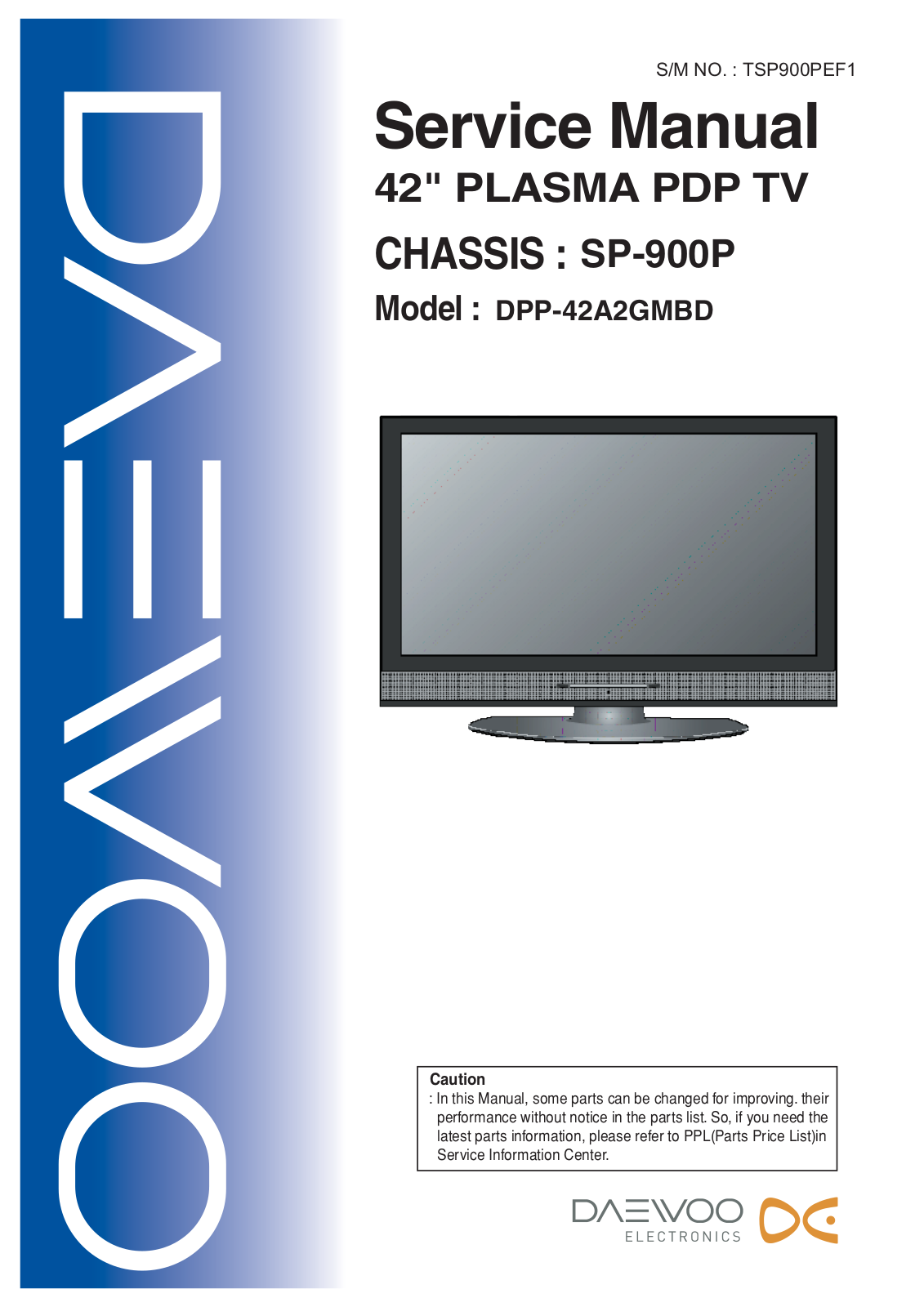
Daewoo SP-900P Service Manual

S/M NO. : TSP900PEF1

Service Manual

42" PLASMA PDP TV

CHASSIS : SP-900P

Model : DPP-42A2GMBD

Caution

:In this Manual, some parts can be changed for improving. their performance without notice in the parts list. So, if you need the latest parts information, please refer to PPL(Parts Price List)in Service Information Center.


Contents


I. Parts with the exception of MODULE


1.

Safety Precautions .................................................................................................................

3

2.

Product Specification .............................................................................................................

4


2-1. SPECIFICATION ............................................................................................................

4


2-2. Available Input Signal .....................................................................................................

6

3.

The Feature of Inside .............................................................................................................

7


3-1. Main PCB’s Connection Diagram ...................................................................................

7


3-2. Main PCB’s Block Diagram.............................................................................................

7


3-3. Power Specification ........................................................................................................

8

4.

Default Setting in User Menu OSD ......................................................................................

10

5.

Service Mode .......................................................................................................................

12

6.

Adjusting Method .................................................................................................................

15


6-1. MODULE POWER Adjustments and Test Point Locations...........................................

15


6-2. White Balance Adjustments..........................................................................................

15

7.

Noticeable Points While Assembling....................................................................................

17

8.

Software Upgrade Methord ..................................................................................................

19


8-1. Pic upgrade ..................................................................................................................

19


8-2. Flash Upgrade ..............................................................................................................

24

9.

Trouble Shooting ..................................................................................................................

30

10. Assembly List .....................................................................................................................

45

11. Structure of PDP SET ........................................................................................................

46

12. Exploded View ...................................................................................................................

51

II. Parts of MODULE


1. PDP MODULE SERVICE MANUAL


-2-

I. Parts with the exception of MODULE

1. Safety Precautions

(1)When moving or laying down a PDP Set, at least two people must work together. Avoid any impact towards the PDP Set.

(2)Do not leave a broken PDP Set on for a long time. To prevent any further damages, after checking the condition of the broken Set, make sure to turn the power (AC) off.

(3)When opening the BACK COVER, you must turn off power (AC) to prevent any electric shock. When PDP is operating, high voltage and high current inside the Set can cause electric shocks.

(4)When loosening screws, check the position and type of the screw. Sort out the screws and store them separately for reassembling. Because screws holding PCBs are working as electric circuit GROUNDING, make sure to check if any screw is missing when assembling/reassembling. Do not leave any screws inside the set.

(5)If you open the BACK COVER, you will see a

Panel Gas Exhaust Tube (Picture. 1-1) inside the bracket. If this part is damaged, the entire PDP PANEL must be replaced. Therefore, when working with the set, be careful not to damage this part.

(6) A PDP Set contains different kinds of connector cables. When connecting or disconnecting cables, check the direction and

position of the cable beforehand.

Picture.1-1 Panel Gas Exhaust Tube

(7)Connect/disconnect the connectors slowly with care especially FFC (film) cables and FPC cables. Do not connect or disconnect connectors instantaneously with force, and handle them carefully for reassembling.

(8)Connectors are designed so that if the number of pins or the direction does not match, connectors will not fit. When having problem in plugging the connectors, check their kind, position, and direction.

-3-

2. Product Specification

-4-

Daewoo SP-900P Service Manual

Product Specification

-5-

Product Specification

2-2. Available Input Singnal

1) PC&HDMI

-6-

3. The Feature of Inside

3-1. Main PCB’s Connection Diagram

Fig.1 Main PCBs Block Diagram

3-2. Main PCB’s Block Diagram

Fig.2 Signal Block Diagram : DPP-42A2

-7-

The Feature of Inside

3-3. Power Specification

-8-

The Feature of Inside

3) Connector

-9-

4. Default Setting in User Menu OSD

4-1. Picture

1) Mode

4-2. Sound

1) Mode

-10-

Default Setting in User Menu OSD

4-3. Screen

1) Mode

4-4. Feature

1) Mode

4-5. Time Setting

1) Mode

4-6. ISM

1) Mode

-11-

5. Service Mode

5-1. Default Value of PW338B_1 and PW338B_2

5-2. FrontEnd_1

-12-

Service Mode

5-3.

FrontEnd_2

5-4.

MGDI

5-5. Msp46XD

5-6. Misc

-13-

Service Mode

5-7.Panel

5-8. Reset

-14-

6. Adjusting Method

6-1. MODULE POWER Adjustments and Test Point Locations v Video pattern condition : 100 IRE Full White Pattern

v Adjust voltages (Vadd, Vsus) to the values that module maker labeled on the PDP panel. If there are some problems in picture after adjusting, you should classify that PDP module as a fault and contact to PDP module maker.

1)Vd (Vadd Voltage) : Data address voltage

-Measurement equipment: Digital Volt Meter (DC Volt mode)

-TP: P812 #3

-Adjusting Volume: VR901

-Adjusting Voltage: Voltage written in the Label, which is located in the upper middle side of PDP Module. (Typical Voltage: 55~66 V)

2)Vs (Vsus Voltage): Sustain voltage

-Measurement equipment: Digital Volt Meter (DC Volt mode)

-TP: P812 #9

-Adjusting Volume: VR951

-Adjusting Voltage: Voltage written in Label, which is located in the upper middle side of PDP Module. (Typical Voltage: 180 ~200 V)

6-2. White Balance Adjustments

1) Apply 5 Step Gray Scale pattern to Video input terminal

100%

80%

60%

40%

20%

0%


High Level Reference


Low Level Reference


2)Check initial data of User Menu (refer to 4-1.Picture(Dynamic))

3)To enter Service mode, press button “ VOL DOWN -> MUTE -> RECALL -> MUTE “on the remote control and select PW338_1, then check initial data of Service mode (refer to

5. Service Mode).

4)Attach a sensor of White Balance Meter (CA-100) to 80% of white level on the screen.

5)Adjust White Balance by varying Gain of R, G, B

· Gain of R, G, B should be adjusted to DP+ 10, if out of these range then classify as a fault.

-15-

Adjusting Method

·Set Color Coordinate to x=0.275 + 0.005, y=0.285 + 0.005 (Low: 0.295) and the Color Temperature should be over 10,000-degree K (standard R&D center equipment).

6)Attach a sensor of White Balance Meter to 40% of white level on the screen.

7)Adjust White Balance by varying the BIAS values of R, G, B

·BIAS Values of R,G,B should be adjusted to DP + 10 ,if out of these range then classify as a fault.

·Set the Color Coordinate to x=0.275 + 0.003, y=0.295 + 0.003 (standard R&D center equipment).

·Does not need to adjust if the deviation of color coordinate is within + 0.003.

8)Repeat No 4) to No 7) until getting the Color Coordinate is x=0.275 + 0.003, y=0.295 + 0.003 at 40% and x=0.275 + 0.005, y=0.285 + 0.005 at 80% white level. Then adjust Sub Contrast to over 140 Cd/m2 after attaching a sensor of White Balance Meter to 100% of white level on the screen.

9)To exit from Service mode, press Menu button on the remote control.

-16-

Loading...
+ 36 hidden pages