

Daewoo SP-120 Service Manual

This file is provided FREE OF CHARGE from the
electromaniacs.com community
You are free to distribute this file to other persons
who needs it , but without of charge
Also on
thousands of service manuals , schematics free of
charge
http://electromaniacs.com you can find
42” PLASMA PDP MONITOR
CHASSIS : SP-120
MODEL : PDS4250
NOV.2003

Contents
I. Parts with the exception of MODULE
1. Safety Precautions
3
2. Product Specification
2-1. SPECIFICATION 4
2-2. Available Input Signal 6
3. BLOCK DIAGRAM 8
4. Description Of Each BLOCK
4-1. A/V BLOCK 9
4-1-1. A/V BLOCK DIAGRAM 9
4-1-2. VIDEO PCB 10
4-1-3. JACK PCB 14
4-1-4. KEY PCB 15
4-1-5. LED PCB 15
4-2. POWER PCB 16
4-3. BASIC CONGIFURATION 17
5. SERVICE MODE
5-1. Entering SERVICE MODE 18
5-2. Default Values For SERVICE MODE Items 18
5-3. Description Of SERVICE MODE Items 19
6. Adjusting Method
6-1. Adjusting WHITE BALANCE 23
6-2. Adjusting POWER PCB 23
7. SOFTWARE UPGRADE Method 25
8. Main PCB Trouble Diagnosis 28
8-1. VIDEO & JACK PCB Trouble Diagnosis 28
8-2. POWER PCB Trouble Diagnosis 33
9. TROUBLE SHOOTING
9-1. Facts You Must Know When Diagnosing And Repairing 34
9-2. Representative Symptoms When Each PCB Breaks Down 34
9-3. Trouble Diagnosis And Repairing Method For Representative Symptoms 35
10. ASSEMBLY LIST 39
11. EXPLODED VIEW 42
II. Parts of MODULE
1. Safety Precautions
43
2. Formation and Specification of Module 46
3. Adjustment 47
4. Trouble Shooting 52
4-1 Checking for No Picture 52
4-2 Hitch Diagnosis Following Display Condition 54
-1-

4-2-1. 4/7 or 3/7 of the screen doesn’t be shown
54
4-2-2. Screen doesn’t be shown as Data COF 54
4-2-3. It is generated unusual pattern of Data COF IC unit 55
4-2-4. Regular Stripe is generated about the quantity of one Data COF IC or more 56
4-2-5. Screen doesn’t be shown at all as scan COF 56
4-2-6. Regular stripe is generated at regular internal on the whole screen 57
4-2-7. Data copy is generated to stripe direction 57
4-2-8. One or more stripe is generated on the screen 58
4-2-9. One or more horizontal line is generated on screen 58
4-2-10. Lightness of screen is wholly darken though there is input-signal-pattern 58
4-2-11. Different color is shown partially during full-white-screen or electric discharge is
generated during full-black-screen 59
4-2-12. Full-white pattern it happened that the lightness of middle is darken while full-white
pattern 59
4-2-13. Some lightness of some color doesn’t not generated well 59
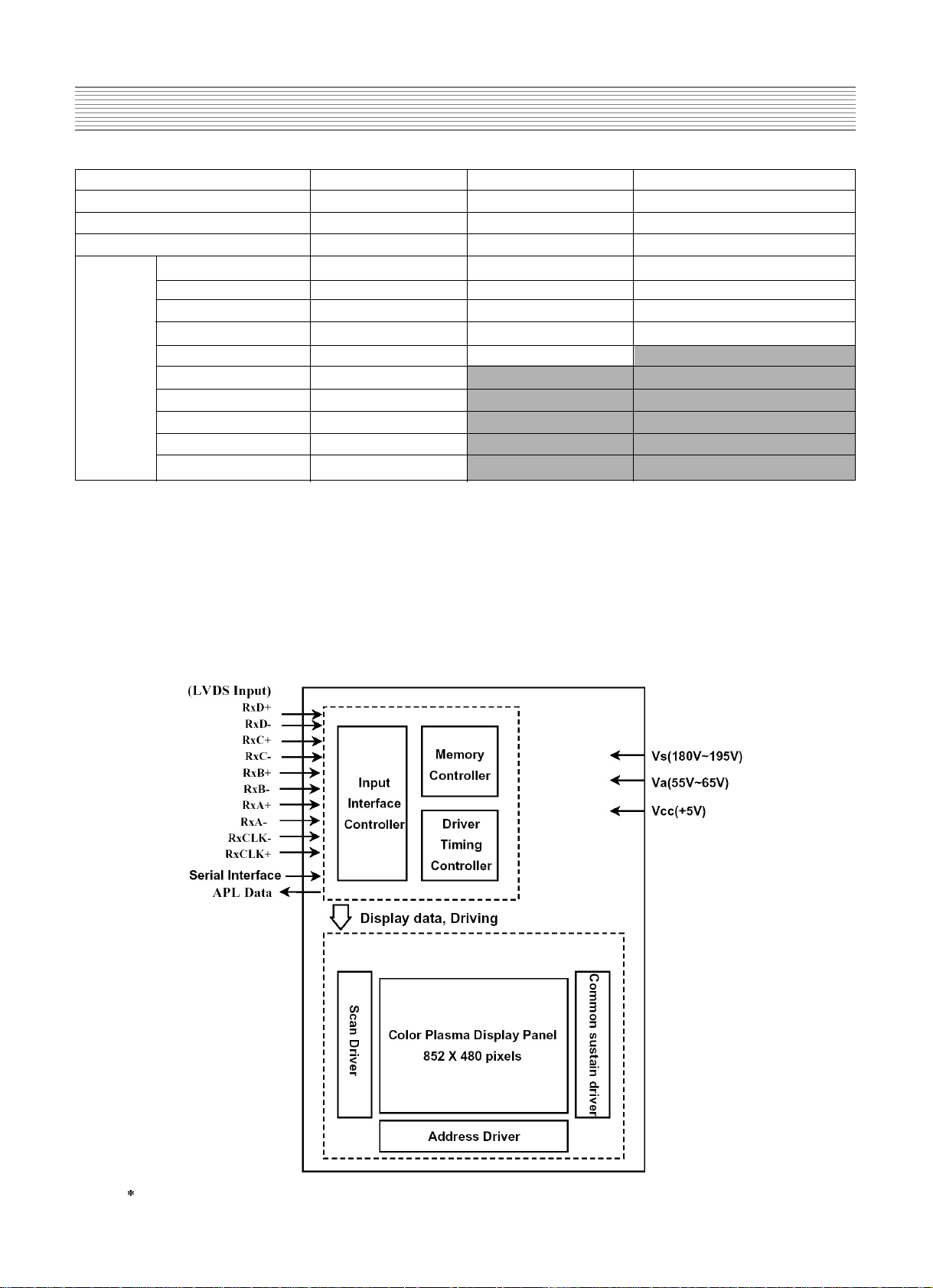
5. Block Diagram of Module 60
-2-
-3-
1. Safety Precautions
I. Parts with the exception of MODULE
1. Safety Precautions
(1) When moving or laying down a PDP Set, at least two people must work. Avoid any impact towards
the PDP Set.
(2) Do not leave the broken PDP Set on for a long time. To prevent any further damages, after check the
condition of the broken Set, make sure to turn the power (AC) off.
(3) When opening the BACK COVER, turn off the power (AC) to prevent electric shock. When a PDP
is on, high voltage and high current exist inside the Set.
(4) When loosening screws, check the connecting position and type of the screw. Sort out the screws
and store them separately. Because screws holding PCB are working as electric circuit
GROUNDING, make sure to check if any screw is missing when assembling.
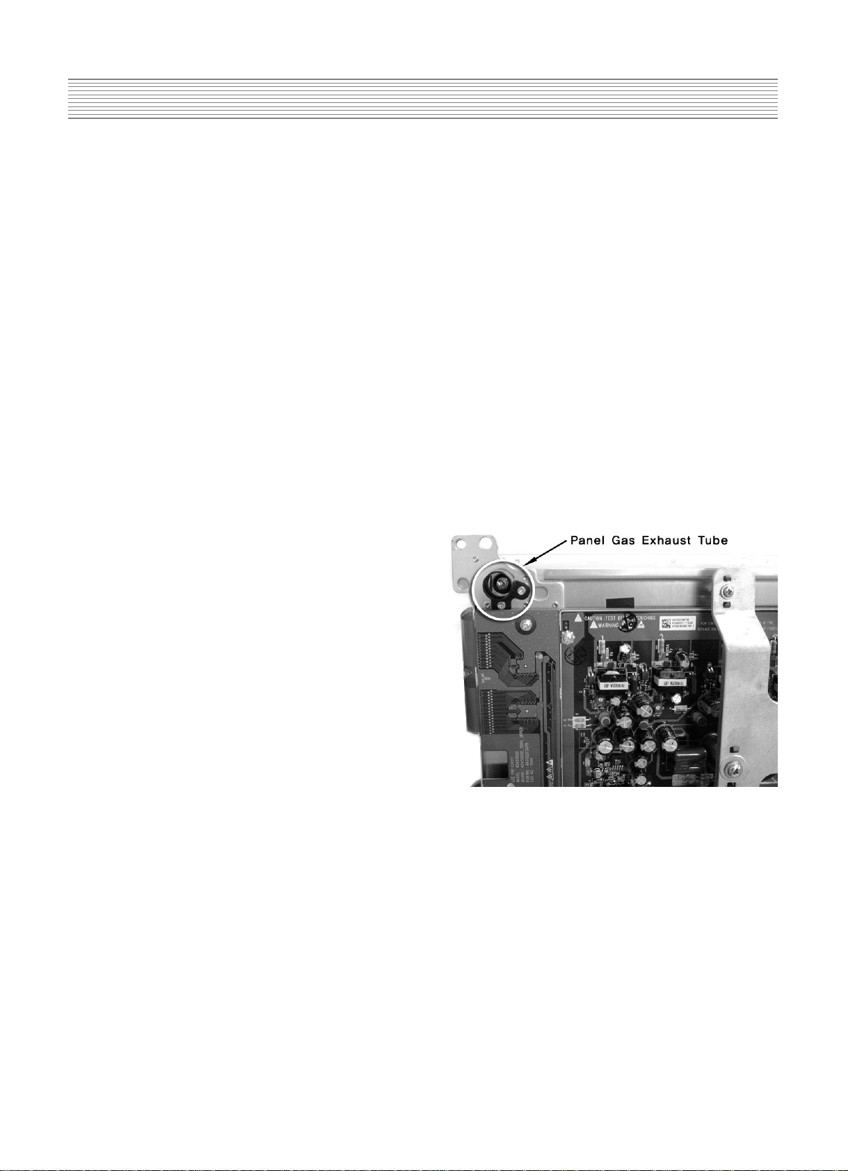
(5) If you open the BACK COVER, you will see a
Panel Gas Exhaust Tube (Fig. 1). If this part is
damaged, entire PDP PANEL must be replaced.
Therefore, when working, be careful not to
damage this part.
Fig 1. Panel Gas Exhaust Tube
(6) A PDP Set contains a different kind of connector cables. When connecting or disconnecting
connector cables, check the direction and position of the cable beforehand.
(7) When disconnecting connectors, unplug the connectors slowly with care. Especially when
connecting/disconnecting FFC (film) cables or FPC cables, do not unplug the connectors too much
instantaneously or strongly, and always handle the cables with care.
(8) Connectors are designed so that if the number of pins or the direction does not match, connectors
will not fit. When having problem in plugging the connectors, make sure to check their kind,
position, and direction.
-4-
2. Product Specification
I T E M S P E C I F I C A T I O N REMARK
1. GENERAL
1-1. MODEL NO DSP-4222LVS(G, W)
1-2. CHASSIS NO SP-120
1-3. SCREEN SIZE 42 (16:9)
1-4. COUNTRY Europe
1-5. RESOLUTION 852(H) X 480(V)
1-6. REMOCON TYPE R-V2A02
1-7. SAFETY STANDARD CE(CLASS B), CB
2. MECHANICAL
2-1. APPEARANCE
1) WITHOUT STAND
WxHxD=1,044 x 631 x 82.8 mm
2) WITH STAND
WxHxD=1,044 x 705.9 x 310 mm
3) CARTON BOX
WxHxD=1,256 x 800 x 327 mm
2-2. WEIGHT
1) WITHOUT STAND
28.2 Kg
2) WITH STAND
32.7 Kg
3. ELECTRICAL
3-1. VIDEO INPUT
COMPOSITE (NTSC, PAL, SECAM, PAL-M/N, NTSC4.43)
& S-VHS (50/60Hz Y/C) 1 PORTS SCART(CVBS/RGB) 2 PORTS
3-2. DTV/DVD INPUT 1080i, 720P, 480P , 480i
(Y, Pb/Cb, Pr/Cr, COMPONENT SIGNAL) 2 PORTS
3-3. PC INPUT
VGA ~ UXGA (15 PIN D-SUB) 1 PORT
3-4. DVI INPUT
DVI-D(DVI JACK) 1 PORT
3-5. SOUND INPUT
VIDEO 3 PORTS, DTV/DVD 2 PORTS,PC 1 PORT,DVI 1 PORT
3-6. SPEAKER OUTPUT 8W(R) + 8W(L)
3-7. POWER REQUIREMENT AC 100V~240V, 50/60Hz
3-8. POWER CONSUMPTION 320W
3-9. RS-232 CONTROL
COMMUNICATION (EXTERNAL UPGRADE)
3-10. FUNCTION
1) SCREEN MODE *PC: H/V SIZE AND POSITION ADJUSTMENT
*VIDEO : AUTO,16:9,PANORAMA,ENLARGE LB, ENLARGE LBS
*DTV/DVD : AUTO,16:9
2) ZOOM
20 STEP ZOOM
3) OSD
11 LANGUAGES (ENGLISH,KOREAN,GERMAN,ITALIAN,
DUTCH,PORTUGUESE,SPANISH,MEXICAN,RUSSIAN,
CHINESE,FRANCH)
4) OTHERS
STILL, SLEEP MODE , SOUND MODE
2-1. SPECIFICATION
-5-
Product Specification
I T E M S P E C I F I C A T I O N REMARK
4. OPTICAL
4-1. SCREEN SIZE 42 (106Cm) DIAGONAL
4-2. ASPECT RATIO 16:9
4-3. NUMBER OF PIXELS
852(H)X480(V)
4-4. DISPLAY COLOR
16,700,000 COLOR( EACH 8BITS FOR RGB )
4-5. CELL PITCH
1.08(H)X1.08(V)
4-6. PEAK LUMINANCE
300cd/㎡(WITH FILTER GLASS) MIK7253
4-7. CONTRAST RATIO
1000:1 (NO.8)
4-8. VIEWING ANGLE
160(VERTICAL/HORIZONTAL)
5. USERCONTROL & ACCESSORIES
5-1 CONTROL BUTTON(SET) AC POWER BUTTON(PUSH-PULL S/W)
MENU, SELECT, UP, DOWN, LEFT, RIGHT(SOFT S/W)
5-2. REMOTE CONTROL
POWER, INPUT SELECT, CONFIRM (or OK),
( R-V2A02 ) EXTENSION -, EXTENSION +, MENU, UP, DOWN,
VOLUME UP, VOLUME DOWN, SILENCE, PICTURE
MODE, PICTURE STILL, PICTURE SIZE, SOUND
MODE, TIMER SLEEP
5-3. ACCESSORIES
REMOTE CONTROLLER,BATTERY,INSTRUCTION MANUAL,
A/V CABLE, PC CABLE, POWER CORD
OPTION : STAND WALL HANGER, SPEAKER R/L
-6-
Product Specification
Resolution H Freq. (KHz) V Freq. (Hz) Remark Patt No.
640x350 31.469 70.1 IBM 203
37.861 85.1 VESA 11
640x400 24.823 56.4 NEC 15
30.48 60.0 PGA 871
31.469 70.1 IBM (DOS) 204
37.861 85.1 VESA 16
640x480 31.469 59.9 DOS 17
35 66.7 Macintosh 18
37.861 72.8 VESA 19
37.5 75.0 VESA 20
39.375 75.0 IBM 21
43.269 85.0 VESA 22
720x400 31.47 60.0 VGA 876
31.469 70.1 IBM 13
37.927 85.1 VESA 14
720X480 31.54 60.0 480P 953
720X576 15.63 25.0 PAL 950
800x600 35.156 56.3 VESA 23
35.16 57.2 VESA 24
37.879 60.3 VESA 24
48.077 72.2 VESA 25
46.875 75.0 VESA 26
53.674 85.1 VESA 27
832x624 49.726 74.0 Macintosh 28
1024x768 48.193(48.077) 59.3(59.8) Macintosh(OAK) 29
48.363 60.0 VESA 30
53.95 66.1 XGA 890
56.476 70.1 HP&VESA 31
60.241 74.9(74.6) Macintosh 32
60.023 75.0 VESA 33
68.677 85.0 VESA 34
80.66 100.0 Fujitsu 939
70.84 84.0 SUN 926
1152X864 54 60.0 VAX 936
63.851 70.0 VESA 35
67.5 75.0 VESA 36
77.094 85.0 VESA 37
1152x900 61.796 66.0 SUN 38
71.713 76.0 SUN 39
1280X720 45 60.0 720P 954
1280X960 60 60.0 VESA 40
75 75.0 VESA 41
85.938 85.0 VESA 42
2-2. Available Input Signal
(1) PC
-7-
Product Specification
Resolution H Freq. (KHz) V Freq. (Hz) Remark Patt No.
1280X1024 46.433 43.4 VESA 205
63.981 60.0 VESA 44
70.66 66.5 VAX 937
74.88 70.0 NEC 921
78.125 72.0 HP & HITA 206
78.855 74.1 Sony & NEC 46
79.976 75.0 VESA 47
81.13 76.1 SUN 927
91.146 85.0 VESA 48
1600X1200 62.5 48.0 VESA
75 60.0 VESA 50
81.25 65.0 VESA 862
87.5 70.0 VESA 863
93.75 75.0 VESA 864
100 80.0 VESA 865
(2) DTV
-1080i/ 60 Hz
-720P / 60 Hz
-480P / 60 Hz
(3) VIDEO
-PAL, PAL-M, PAL-N
-NTSC , NTSC4.43
- SECAM
-8-
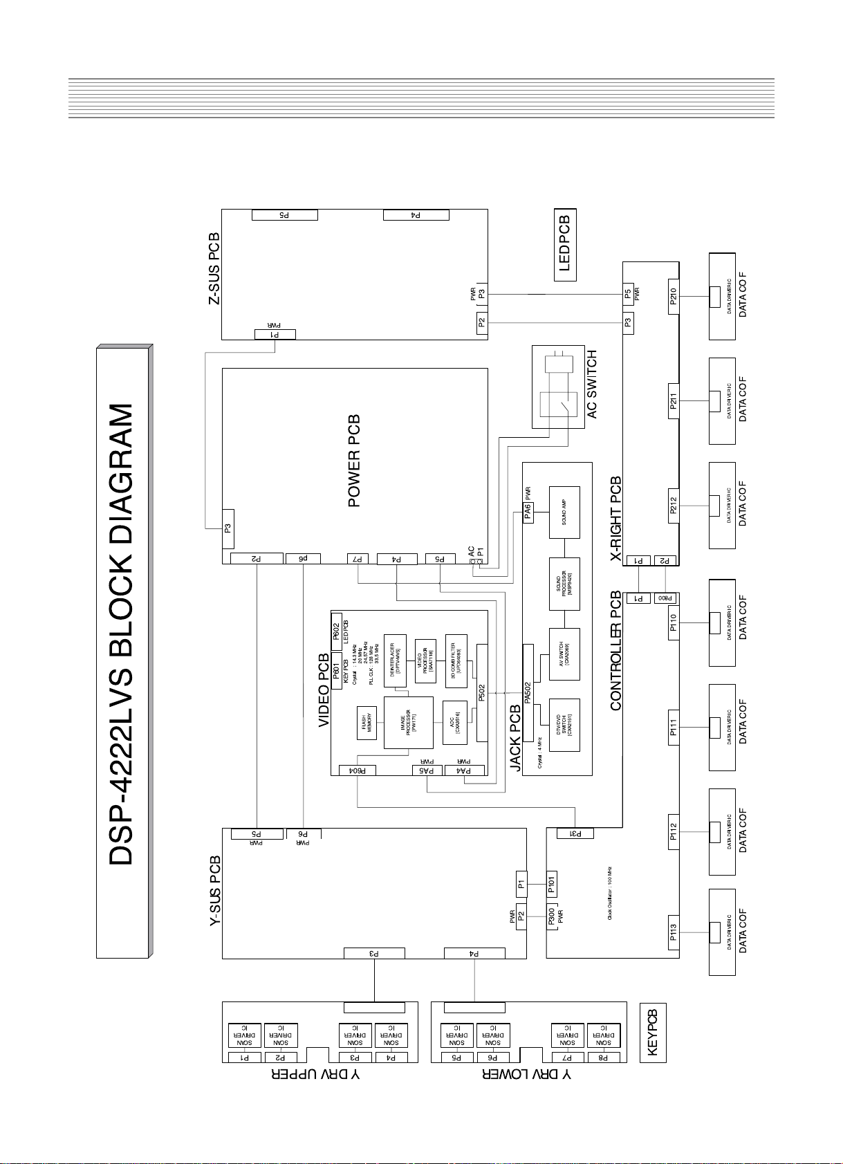
3. BLOCK DIAGRAM
-9-
4. Description Of Each BLOCK
4-1. A/V BLOCK
4-1-1. A/V BLOCK DIAGRAM
to PWR
to PWR
to PWR
to
DIGITAL
P602P601
P12V
P12V
GND
GND
GND
SCL
GND
TXD
RXD
GND
GND
GND
GND
GND
VIN
FB_SC
S_MUTE
MSP_RST
R_SC
G_SC
B_SC
SDA
SEL1
SEL2
SEL3
VPC
HPC
GND
BPC
RPC
GND
GND
B/PB
GND
R/PR
Y_DVDCBCRYOGND
GNDCOGND
GND
GND
GND
G/Y_DTV
GND
GPC
GND
P502
1
50
26
25
1
PA6
1
432
PA502
JACK
PCB
GND
VVS
VHS
VPEN1
GBLKSLP GPEN GSOG
GHSFOUT
DCLKB
DEN
S_RESET
V_MUTE
DVS
DHS
GCLK
GHS
GVS
GCOAST
VIN
R_OUT
L_OUT
RIGHT
LEFT
GREF
VPEN
DECOE
YCOMB
CCOMB
IR
LED_P
GND
GND
GND
E33V
STB5V
COLUM1
COLUM2
COLUM3
DATA1
DATA2
1
5
4
3
2
1
5
4
3
2
6
1
40
2
39
PA4
PA5
P603
1
6
7
8
9
5
3
4
2
NUL
P12V
P12V
GND
GND
P5V
GND
GND
LED_P
LED_P
POWER_CLT
GND
GND
GND
GND
GND
GND
RD2-
RD1+
RD1-
RD2-
RD2+
DISPEN
SCLK
GND
RC2-
RB2+
RC2+
RB1-
RB+
RA1-
RB2-
RA2-
RA1+
RC+
RC-
RA2+
RCLK2-
RCLK1+
RCLK2+
RCLK1-
STB5V
SLE
SDATA
STB5V
1
5
2
3
4
IC600
PW171
IC406
DPTV-MVS
IC401
SAA7118
IC400
u64083
IC500
CXA3516
PA602LED
1
5432 6
1
5432
PA601
KEY PCB
IC706
CXA2151
IC704
CXA2069
IC700
MSP3420
IC702
TDA7480
IC701
TDA7480
10
7
8
6 7 8
26
50
25
-10-
Description Of Each BLOCK
4-1-2.VIDEO PCB
- PROCESS Various Signal (PC, COMPONENT, COMPOSITE ) to produce 24BIT DIGITAL
output
(1) IC and TP
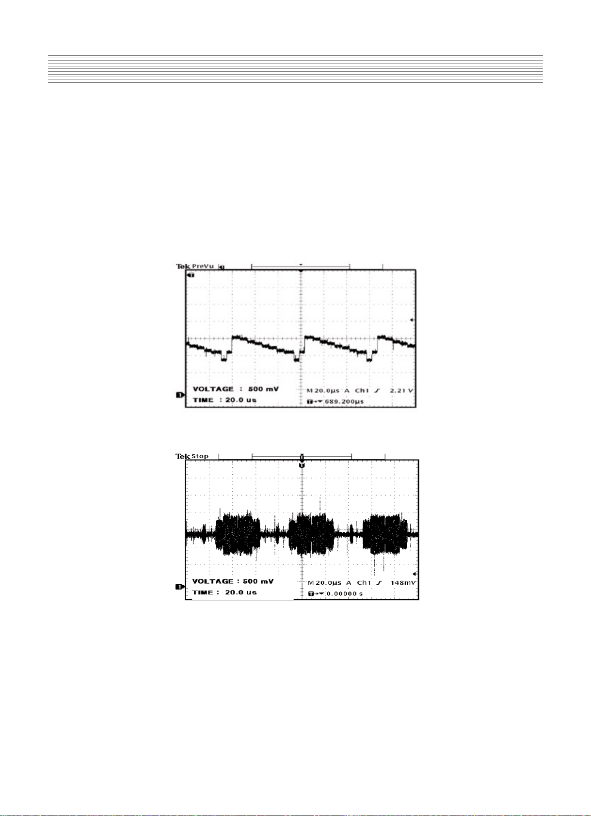
(1) IC400(UPD64083)
-Using 3D COMBFILTER to separate COMPOSITE signal to Brightness
Signal(Y) and Color Signal(C)
*TP ( Input : COLOR BAR PATTERN )
A. YCOMP : Brightness Signal(Y)
B. CCOMP : Color Signal (C)
(2) IC401 (SAA7118E)
-Receive NTSC, SECAM, PAL VIDEO by COMPOSITE(V) , S-VHS(Y.C)
COMPONENT (Y Cb Cr) and process signal
*TP
A. DECOE : CHIP ENABLE part. When signal process is done by IC401, DC 3.3V is
measured.
-11-
Description Of Each BLOCK
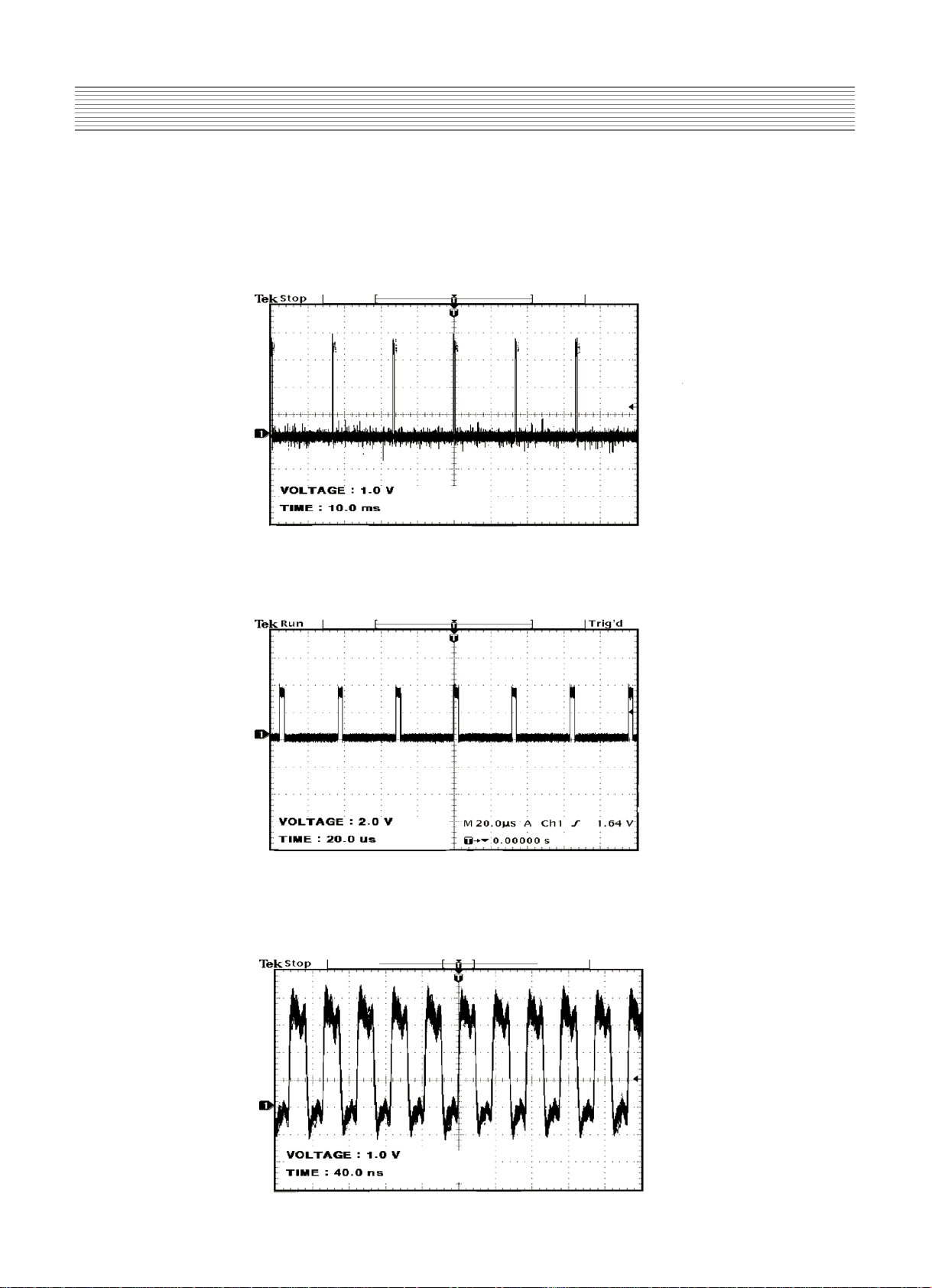
(3) IC406(DPTV-MVS)
-A Scan Rate Converter which converts Interlace signal into Progressive signal
*TP
A. VVS : VERTICAL SYNC (output of DPTV-MVS)
B. VHS : HORIZONTAL SYNC (output of DPTV-MVS)
C. VCLK : CLOCK (output of DPTV-MVS)
-12-
Description Of Each BLOCK
(4) IC500(CXA3516R)
-3-channel 8-bit 165MSPS A/D converter which process PC , DTV signal
* TP
A. GCOAST : COAST CONTOL Signal for PLL (input of CXA3516)
B .GHS : HORIZONTAL SYNC for GRAPHIC (output of CXA3516)
C. GCLK : CLOCK for GRAPHIC (output of CXA3516)
-13-
Description Of Each BLOCK
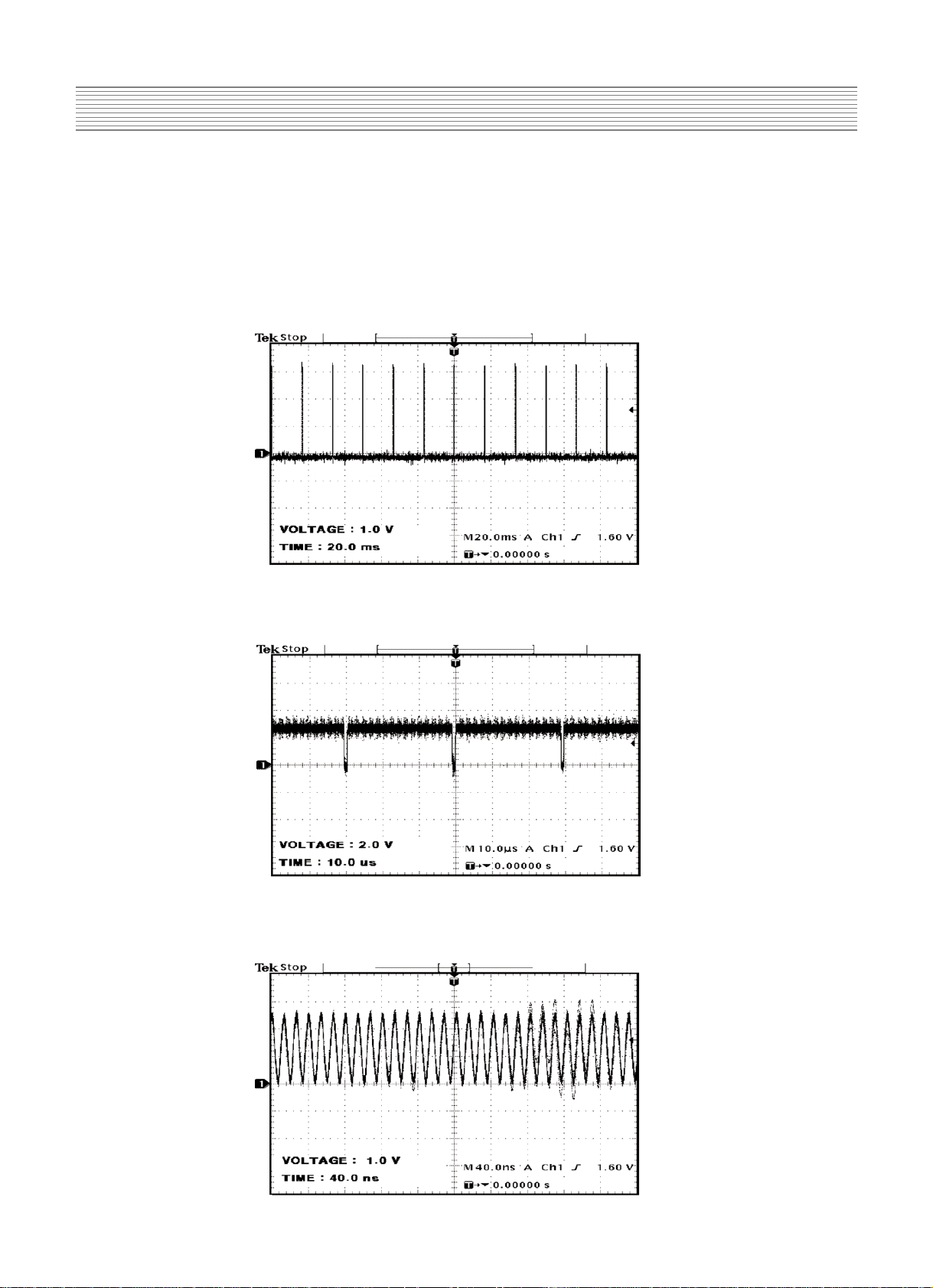
D. GFBK : SYNC for PLL
(5) IC600(PW171)
- Image processor IC
*TP
A. DEN : DATA ENABLE (output of PW171)
B. DHS : HORIZONTAL SYNC (output of PW171)
-14-
Description Of Each BLOCK
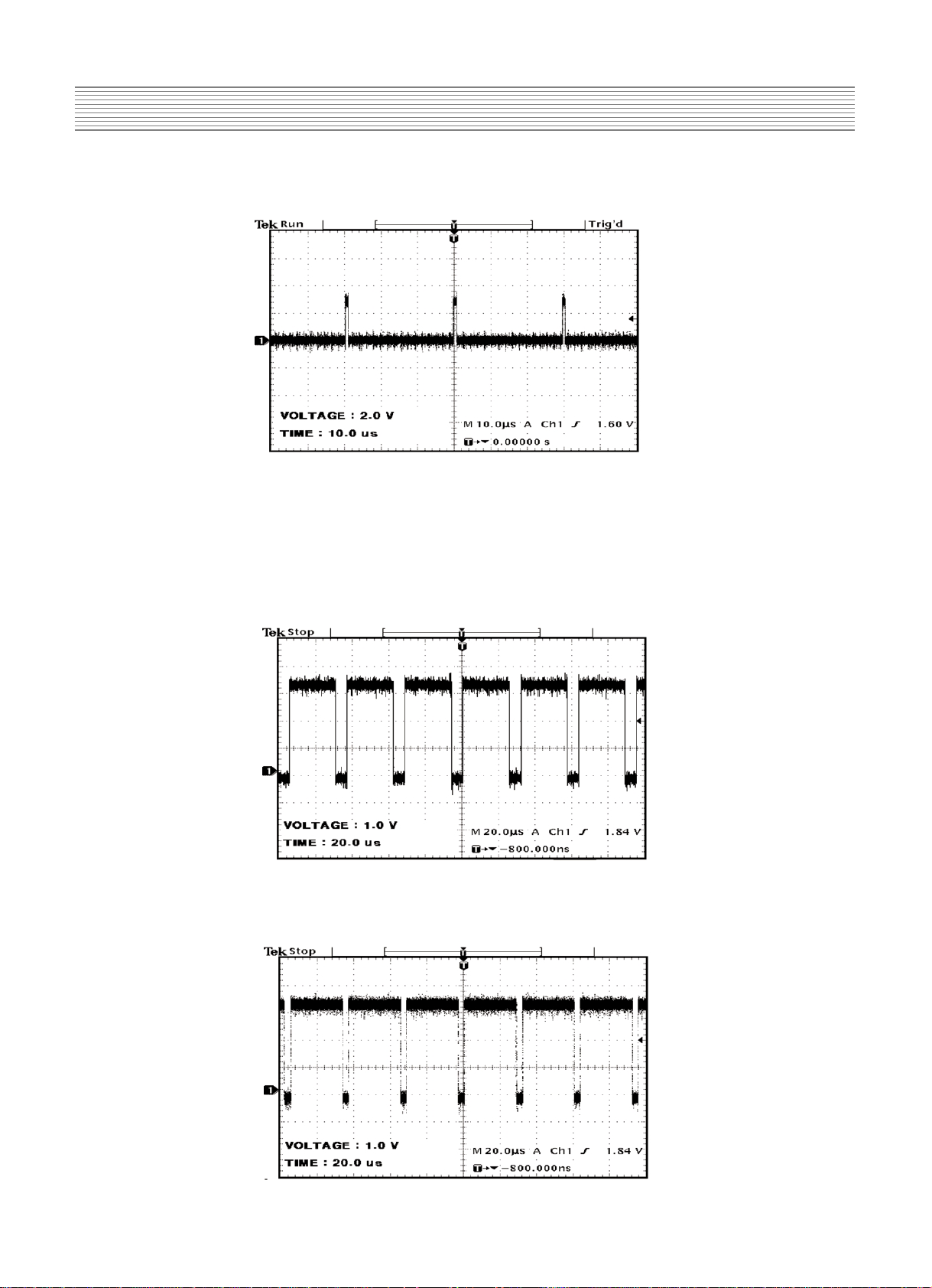
C.DVS : VERTICAL SYNC for DISPLAY (output of PW171)
D. DCLKB : CLOCK for DISPLAY (output of PW171)
4-1-3. JACK PCB
- Separate and process various VIDEO and AUDIO signal
(1) IC706 (VIDEO /SYNC SELECTOR)
- This chooses Y Cb/Pb Cr/Pr or RGB signal to output Y Cb/Pb Cr/Pr, to separate SYNC,
and to perform SYNC COUNTER.
(2) IC704 (AUDIO/VIDEO SWITCH)
- The IC perform AUDIO or VIDEO SWITCHING
(3) IC715 (DIGITAL CONTROLLER)
- DVI CONTROLLER
(4) IC721 (INPUT SELECTOR SWITCH)
- SCART (RGB) SELECTOR SWITCH
(5) IC700 (MULTI STANDARD SOUND PROCDSSOR)
-AUDIO SINGNAL VOLUME control, EQUALIZER control
-15-
Description Of Each BLOCK
*TP
R_OUT(L_OUT) : AUDIO SIGNAL that goes into MSP3420 before AUDIO
PROCESSING
(4) IC701 .IC700 (TDA 7480)
*TP
A. RIGHT(LEFT) :AMP input signal before 30dB amplification
4-1-4.KEY PCB
- Input PCB using KEY
4-1-5.LED PCB
- PCB for REMOCON CONTROL
-16-
Description Of Each BLOCK
4-2. POWER PCB
<Input requirements>
Nominal Input Voltage : AC100V to AC240V (Variation Range - AC85V to AC276V)
Single-Phase full wave
Regulation Method : Transistor Switching Method
Input Frequency : 50~60Hz (Variation range 45Hz to 66Hz)
Inrush Current : 50A zero-peak max at AC264V
Output Voltage is as follows.
No. Output Nominal Variable Voltage Nominal Load current Ripple/Noise
Name Voltage range accuracy current range (mVp-p)*2
(V) (V) *1 (A) (A)
1 Vsus 190 180-195 5V 1.3 0.1~1.3 1000/500
2 Vadd 60 50-80
2V 1 0.1~1 250/500
3 V1 5.1 -
5% 2.5 0.1~3 50/100
4V3 17 -
5% 1 0~1 50/100
(SOUND) -17 -
5% 1 0~1 50/100
5 V4 5.0 - 5% 1.5 0.1~1.5 50/100
6V5 12 -
5% 0.6 0~1 50/100
7 Vstb 5 -
5% 1.5 0~1.5 100/100
Connector number P2 P3 P6
Model name GP390-10P-TS 1-1123723-8 GP390-04P-TS
Maker LG Cable AMP LG Cable
The number of pins 10 8 4
1 Vsus 190V Vsus 190V G
2 Vsus 190V Vsus 190V G
3 Vsus 190V NC V1 5.1V
4 NC G V1 5.1V
5GG
6 G Vadd 60V
7GG
8 G V1 5.1V
9NC
10 NC
Connector
Pin
number
-17-
Description Of Each BLOCK
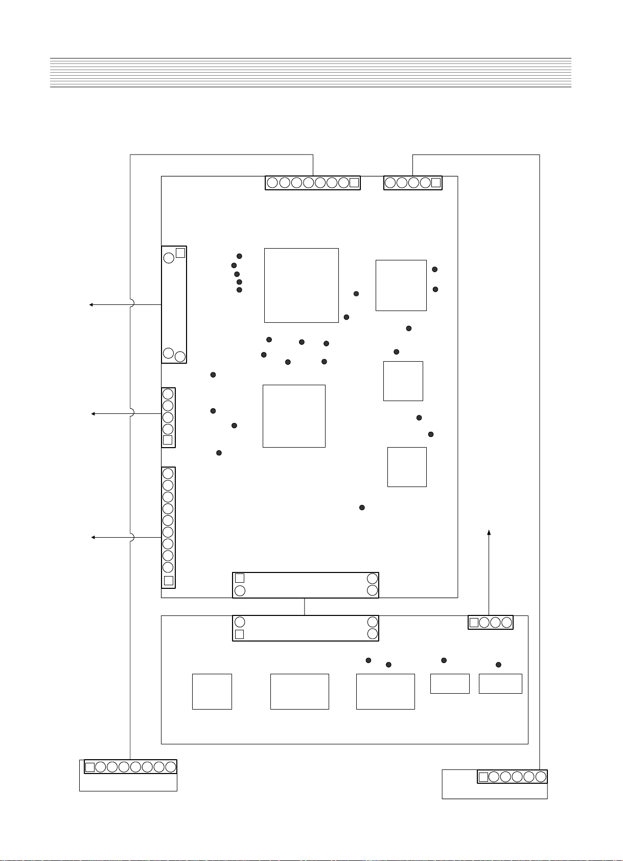
4-3. Basic Configuration
Connector number P4 P5 P7
Model name YMW025-10R YMW025-05R YMW025-04R
Maker YEONHO YEONHO YEONHO
The number of pins 10 5 4
1 NC POWER (ON/OFF) V3 -17V
2NCNCG
3 V5 12V NC G
4 G G V3 17V
5 G Vstb
6 V4 5V
7G
8G
9NC
10 NC
Pin
number
* P2 is connected to P5 of Y-SUS PCB.
P3 is connected to P1 of Z-SUS PCB.
P6 is connected to P6 of Y-SUS PCB.
P4 is connected to PA4 of VIDEO PCB.
P5 is connected to PA5 of VIDEO PCB.
P7 is connected to PA6 of JACK PCB.
Applied Voltage level is specified at the time, when full white pattern displayed on panel.
 Loading...