

Page 1

Service Manual
Chassis : SL-S00T/10T
Page 2

2
Contents
Model line-up using SL-S00T/10T chassis. ................................................................................... 4
1) Mechanical design of DAEWOO models. ............................................................................................................................. 4
2) Mechanical design of hanseatic models. .............................................................................................................................. 4
3) Buyer and Factory Model Names. ............................................................................................................................................ 4
1. Safety Precaution. .......................................................................................................................... 5
2. Preliminary Troubleshooting ....................................................................................................... 6
2-1) LCD TV does not response or remote controller does not work. ...................................................................... 6
2-2) Sound is discontinuous or broken sometimes. ............................................................................................................ 6
2-3) Picture of digital program is sometimes broken and sound is discontinuous. ........................................... 6
2-4) Picture of analog program is noisy. ................................................................................................................................... 6
2-5) Sound is not generated in HDMI mode. .......................................................................................................................... 6
2-6) In spite of 'Auto Adjust', picture size in the PC mode is not completely adapted to the screen. .... 6
2-7) In spite of 'Auto Adjust' in the PC mode, picture is not clear. ............................................................................ 6
3. Product Specifications. ................................................................................................................. 7
3-1) Standard. ........................................................................................................................................................................................... 7
3-2) Available Input Signal. ............................................................................................................................................................... 8
3-3) Available user remote controller. ......................................................................................................................................... 9
4. Block Diagram. ............................................................................................................................. 10
5. Software Update. ......................................................................................................................... 11
5-1) Update using RS-232C cable. .............................................................................................................................................. 11
5-1-1) Preparation. .................................................................................................................................................................... 11
5-1-2) System Configuration. ............................................................................................................................................... 11
5-1-3) Introduction. ................................................................................................................................................................... 11
5-1-4) Tool installation. ........................................................................................................................................................... 12
5-1-5) Procedure. ........................................................................................................................................................................ 12
5-2) Upgrade using USB Memory. ............................................................................................................................................. 14
6. Service mode. ................................................................................................................................ 14
6-1) Using the Service Remote controller. ............................................................................................................................. 14
6-2) Using the User Remote controller (S/N : 48B6360B01). ....................................................................................... 14
7. Hardware Trouble Shooting ...................................................................................................... 16
7-1) No picture or picture with poor quality. ...................................................................................................................... 16
7-1-1) Back-light does not turn on and no LVDS signal. ...................................................................................... 16
7-1-2) No Analog TV is displayed. .................................................................................................................................... 17
7-1-3) No picture in CVBS of AV1 mode. ...................................................................................................................... 18
7-1-4) No picture in RGB of AV1 mode. ........................................................................................................................ 19
7-1-5) No picture in CVBS of AV2 mode. ...................................................................................................................... 20
7-1-6) No picture in CVBS of AV3 mode. ...................................................................................................................... 21
7-1-7) No picture in PC Mode. ............................................................................................................................................ 21
Page 3

7-1-8) No picture in component mode. ......................................................................................................................... 23
7-1-9) No picture in S-video mode. ................................................................................................................................. 24
7-1-10) No picture at external TV connected with AV1(RF-Output). ............................................................. 25
7-1-11) No picture/Sound in HDMI mode. ................................................................................................................... 26
7-2) When no sound output from internal speaker. ........................................................................................................ 27
7-2-1) No sound of analog TV mode. ............................................................................................................................. 27
7-2-2) No sound of AV1 mode. .......................................................................................................................................... 28
7-2-3) No sound of AV2 mode. .......................................................................................................................................... 29
7-2-4) No sound of PC/DVI Sound mode. .................................................................................................................... 30
7-2-5) No sound of Component Sound mode. .......................................................................................................... 31
7-2-6) No sound of AV3/S-Video Sound mode. ........................................................................................................ 32
7-2-7) No sound of Digital TV/HDMI mode. ............................................................................................................... 33
7-2-8) No sound at external TV connected with AV1(RF-Output). .................................................................. 33
7-2-9) No Picture or No Sound In the Media(USB) Mode. .................................................................................. 34
7-2-10) Sound In/Output of AMP. .................................................................................................................................... 34
7-3. When supply voltage of SMPS is not good. ............................................................................................................... 35
3
7-3-1) 32, 37 inch Model (FEL-3237VN). ........................................................................................................................ 35
7-3-2) 42 inch Models (FEL-4247VN)............................................................................................................................... 36
8. Parts List. ....................................................................................................................................... 37
8-1. Main Board Part List. ............................................................................................................................................................... 37
8-2. Differential Part List. ................................................................................................................................................................ 48
8-2-1. Differential Part of Main Chassis depending on Panel Maker. ............................................................. 48
8-2-2. Differential Part of Main Chassis depending on Panel type. ................................................................ 48
8-3. Union Part List. ........................................................................................................................................................................... 48
8-4. Cable Lists. .................................................................................................................................................................................... 48
8-5. SMPS Part list. ............................................................................................................................................................................. 49
8-5-1) FEL-3237VN. ................................................................................................................................................................... 49
8-5-2) FEL-4247VN. ................................................................................................................................................................... 52
9. Mechanical Assembly Drawing. ................................................................................................ 55
9-1. Model : 32L1. ............................................................................................................................................................................... 55
9-2. Model : 32L2. ............................................................................................................................................................................... 56
9-3. Model : 37L1. ............................................................................................................................................................................... 57
9-4. Model : 37L2. ............................................................................................................................................................................... 58
9-5. Model : 42L1. ............................................................................................................................................................................... 59
9-6. Model : 42L2. ............................................................................................................................................................................... 60
10. Schematics. .................................................................................................................................. 61
****Caution
Some contents or parts in this manual may be changed for improving performanace without notice.
If the latest information is needed, please refer to Service Information Ceter.
Page 4
4
Model line-up using SL-S00T/10T chassis.
1) Mechanical design of DAEWOO models.
Brand
DAEWOO
2) Mechanical design of hanseatic models.
Brand L1 Cabinet
hanseatic Black 1 Tone LC32-260T LC37-260T LC42-260T
3) Buyer and Factory Model Names.
Brand Chassis BYR Model FCT Model
DAEWOO SL-S00T LT32L1 LT32L1B1LM
DAEWOO SL-S00T LT32L1 LT32L1B1SM
hanseatic SL-S00T LC32-260T LT32L1B1LM
hanseatic SL-S00T LC32-260T LT32L1B1SM
DAEWOO SL-S00T LT37L1 LT37L1B1LM
hanseatic SL-S00T LC37-260T LT37L1B1LM
DAEWOO SL-S00T LT42L1 LT42L1B1LM
hanseatic SL-S00T LC42-260T LT42L1B1LM
DAEWOO SL-S10T LT42L1FH LT42L1B1LF
hanseatic SL-S10T LC42-300FT LT42L1B1LF
DAEWOO SL-S00T LT32L2 LT32L2BSLM
DAEWOO SL-S00T LT32L2 LT32L2BSSM
DAEWOO SL-S00T LT32L2K LT32L2BKLM
DAEWOO SL-S00T LT32L2K LT32L2BKSM
DAEWOO SL-S00T LT32L2R LT32L2BRLM
DAEWOO SL-S00T LT32L2R LT32L2BRSM
DAEWOO SL-S00T LT32L2Z LT32L2BZLM
DAEWOO SL-S00T LT32L2Z LT32L2BZSM
DAEWOO SL-S00T LT37L2 LT37L2BSLM
DAEWOO SL-S00T LT37L2K LT37L2BKLM
DAEWOO SL-S00T LT37L2R LT37L2BRLM
DAEWOO SL-S00T LT37L2Z LT37L2BZLM
DAEWOO SL-S00T LT42L2 LT42L2BSLM
DAEWOO SL-S00T LT42L2K LT42L2BKLM
DAEWOO SL-S00T LT42L2R LT42L2BRLM
DAEWOO SL-S00T LT42L2Z LT42L2BZLM
DAEWOO SL-S10T LT42L2FH LT42L2BSLF
DAEWOO SL-S10T LT42L2KFH LT42L2BKLF
DAEWOO SL-S10T LT42L2RFH LT42L2BRLF
DAEWOO SL-S10T LT42L2ZFH LT42L2BZLF
L2 Cabinet
Black / Silver LT32L2 LT37L2 LT42L2 LT42L2FH
Black / Gold LT32L2K LT37L2K LT42L2K LT42L2KFH
Black / Red LT32L2R LT37L2R LT42L2R LT42L2RFH
Black / Blue LT32L2Z LT37L2Z LT42L2Z LT42L2ZFH
32 Inch
(SL-S00T)
32 Inch 37 Inch 42 Inch
(SL-S00T) (SL-S00T) (SL-S00T)
37 Inch
(SL-S00T)
42 Inch
(SL-S00T)
42 Inch FHD
(SL-S10T)
Page 5

1. Safety Precaution.
(1) When moving or laying down a LCD Set, please deal with care. Avoid any impact towards the LCD Set.
(2) Do not leave a broken LCD Set on for a long time. To prevent some damages, after check it, make sure to
turn the power (AC) off.
(3) When opening the BACK COVER, you must turn off power (AC) to prevent any electric shock.
(4) When loosening screws, check the connecting position and type of the screw.
Sort out the screws and store them separately, because screws holding PCBs are working as a ground level,
make sure to check if any screw is missing when assembling.
(5) A LCD Set contains different kinds of connector cables.
Before connecting or disconnecting connector cables, check the direction and position of the cable beforehand.
5
(6) When disconnecting connectors unplug the connectors slowly with care.
(7) Connectors are designed so that if the number of pins or the direction does not match, connectors will not
fit. When having problem in plugging the connectors, make sure to check their kind, position, and direction.
Page 6

6
2. Preliminary Troubleshooting
2-1) LCD TV does not response or remote controller does not work.
① Check the power cord to be plugged.
② Check the battery of the remote controller.
2-2) Sound is discontinuous or broken sometimes.
① Check [SOUND] -> [AVC] is [ON].
② Set the sound into 'Mono'.
③ Ask for the broadcasting station if the RF cable connection has no problem.
④ Ask for the broadcasting station to check signal strength of RF cable.
2-3) Picture of digital program is sometimes broken and sound is discontinuous.
① Digital program has a little problem because of signal receiving status.
② Check the RF cable connection.
③ Ask for the broadcasting station if the RF cable connection has no problem.
④ Ask for the broadcasting station to check signal strength of RF cable.
2-4) Picture of analog program is noisy.
① Check the RF cable connection.
② Check [Picture] -> [Noise Reduction] is ON.
③ Change the [Install] -> [Analog or Digital Manual Tuning] -> [Fine] value.
④ Ask for the broadcasting station to check signal strength of RF cable.
2-5) Sound is not generated in HDMI mode.
① Reconnect HDMI jack.
② DVI cable has no sound. Check the output signal of device to be connected to LCD TV.
③ If you want to use DVI-HDMI cable, to listen sound, stereo cable should be connected to PC audio jack.
2-6) In spite of 'Auto Adjust', picture size in the PC mode is not completely adapted to the screen.
① Check if the input signal is available.
② Ensure that the desktop has no black area.
③ Some errors (picture position problem) will be occurred according to certain video card.
In this case, you should adjust 'Frequency' control.
2-7) In spite of 'Auto Adjust' in the PC mode, picture is not clear.
① Adjust 'Phase' control.
Page 7
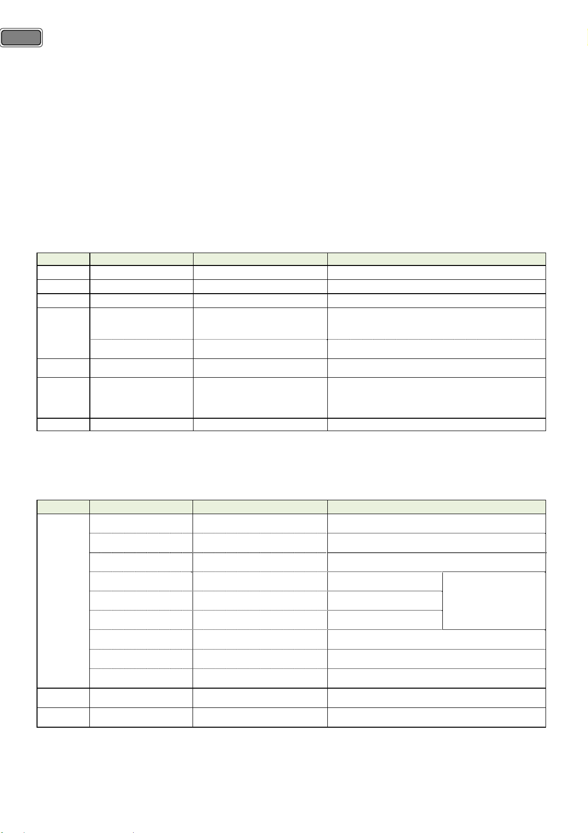
3. Product Specifications.
3-1) Standard.
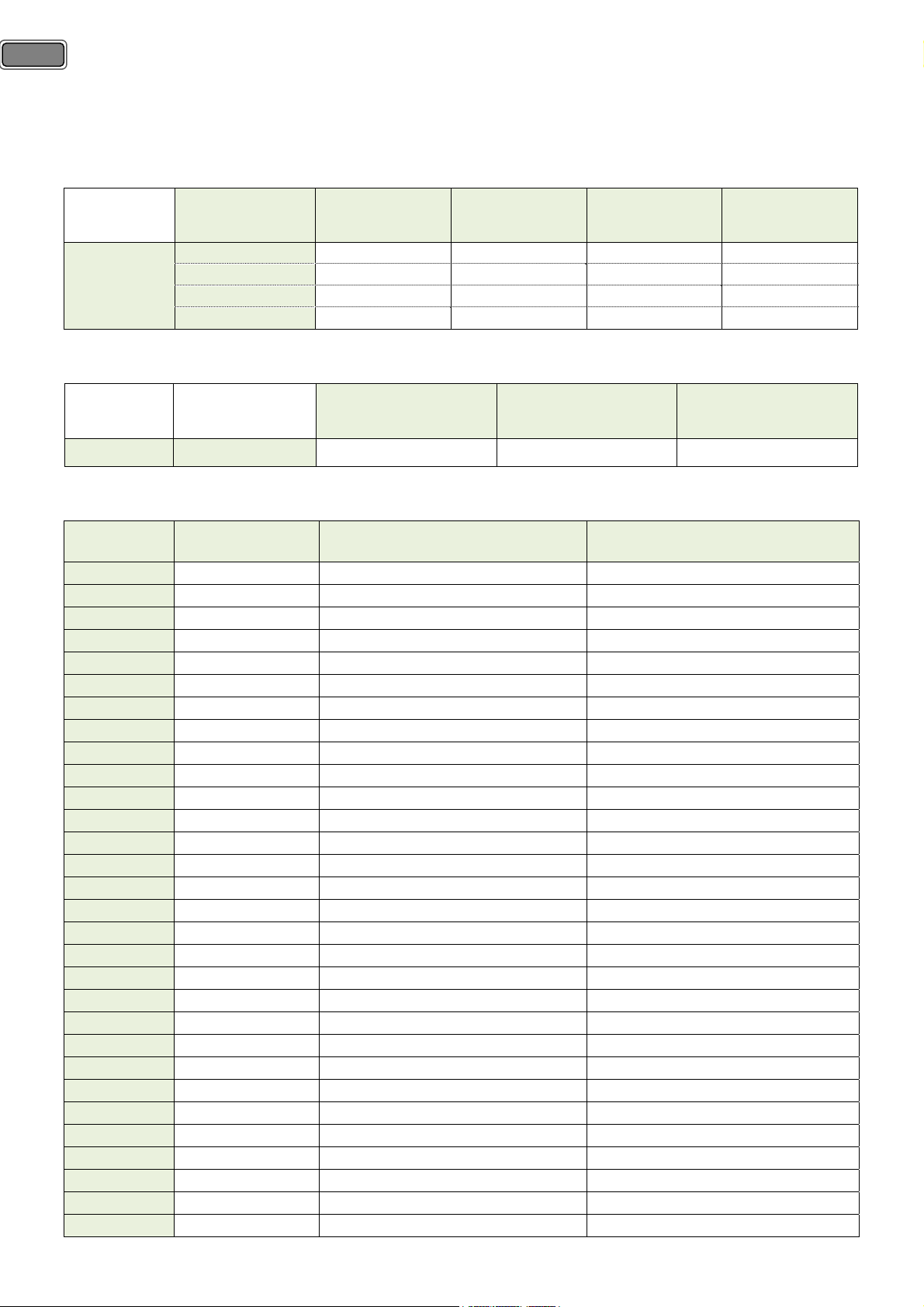
32 Inch HD Model 37 Inch HD Model 42 inch HD Model 42 inch Full HD Model
Screen Size 32” 37” 42” 42”
Aspect Ratio 16 : 9 16 : 9 16 : 9 16 : 9
7
LCD Panel
Dimension (W×H×D) 796X515.5(563)X87(244) 927X596(656)X98(320) 1033x655(714)x106(320) 1033x655(714)x106(320)
Max Power Consumption 115W 150W 170W 180W
TV System PAL-I, B / G, D/K, SECAM-B/G, D/K, L/L’, DVB-T
Power Source 220-240V, 50-60Hz
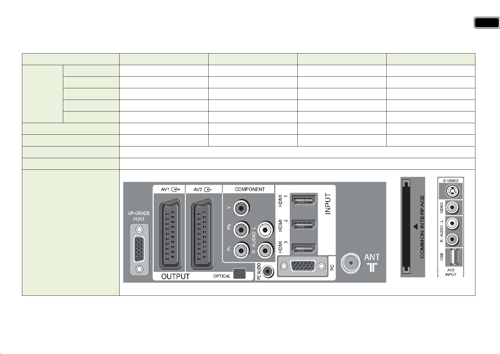
In/Output Jack
Resolution 1366 × 768 1366 × 768 1366 × 768 1920 × 1080
Pixel Pitch 0.42x0.42 0.51 × 0.51 0.6x0.6 0.484x0.484
Contrast Ratio 10,000:1 10,000:1 10,000:1 12,000:1
※ In Dimension, the size in the brackets is set dimension with stand. Owing to our policy of continuous improvement, specifications may change.
Page 8
8
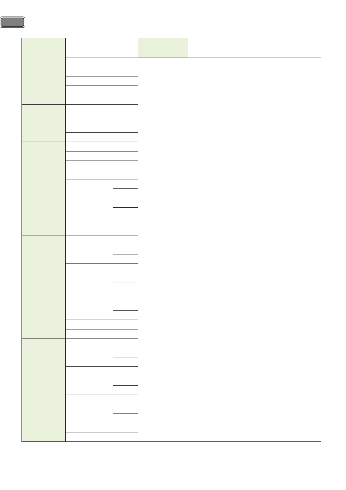
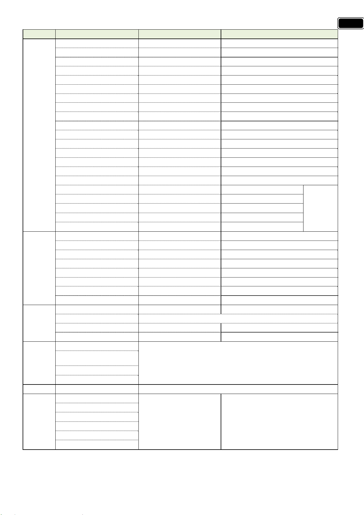
3-2) Available Input Signal.
Interface Source VF Interface Source VF
RF
Video
S-VIDEO
Component
PC
HDMI
PAL-B/G, B/H 50Hz
DVB-T 50Hz
PAL-B/G, B/H 50Hz
PAL-60 60Hz
NTSC-M 60Hz
NTSC-4.43 60Hz
PAL-B/G, B/H 50Hz
PAL-60 60Hz
NTSC-M 60Hz
NTSC-4.43 60Hz
480I 60Hz
576I 50Hz
480P 60Hz
576P 50Hz
50Hz
720P
60Hz
50Hz
1080I
60Hz
60Hz
1080P*
50Hz
60Hz
640 x 480
72Hz
75Hz
60Hz
800 x 600
72Hz
75Hz
60Hz
1024 x 768
70Hz
75Hz
1360 x 768 60Hz
1920 x 1080* 60Hz
60Hz
640 x 480
72Hz
75Hz
60Hz
800 x 600
72Hz
75Hz
60Hz
1024 x 768
70Hz
75Hz
1360 x 768 60Hz
1920 x 1080* 60Hz
Media USB Memory
Precautions when using the USB device
• Only a USB storage device is recognizable.
• If the USB storage device is connected through a USB hub, the
device is not recognizable.
• A USB storage device using an automatic recognition program
may not be recognized.
• A USB storage device which uses its own driver may not be
recognized.
• The recognition speed of a USB storage device may depend on
each device.
• Please do not turn off the TV or unplug the USB device when
the connected USB storage device is working. When such device
is suddenly separated or unplugged, the stored files or the USB
storage device may be damaged.
• Please do not connect the USB storage device which was
artificially maneuvered on the PC. The device may cause the
product to malfunction or fail to be played. Never forget to use
only a USB storage device which has normal music files or image
files.
• Please use only a USB storage device which was formatted as a
FAT or NTFS file system provided with the Windows operating
system. In case of a storage device formatted as a different utility
program which is not supported by Windows, it may not be
recognized.
• Please connect power to a USB storage device which requires
an external power supply. If not, the device may not be
recognized.
• Please connect a USB storage device with cable is offered by
USB maker. If connected with cable is not offered by USB maker
or an excessively long cable, the device may not be recognized.
• Some USB storage devices may not be supported or operated
smoothly.
• File alignment method of USB storage device is similar to
Window XP and filename can recognize up to 25 European
characters.
• Please backup important files because data on USB device may
be damaged. Data management is consumer’s responsibility and
as a result, the manufacturer does not cover data damage.
Supported format
1. Music : This TV supports only MP3 format which has sampling
rate of 44.1kHz.
2. Photo : This TV supports only JPEG format.
* :
Full HD Model Only
Page 9
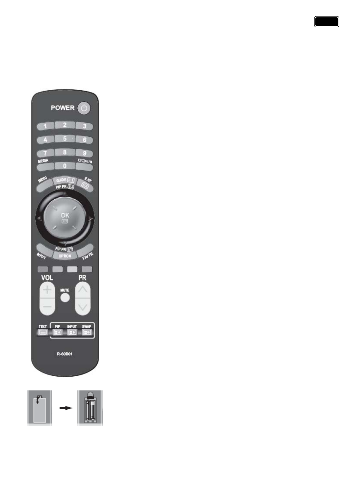
3-3) Available user remote controller.
1. POWER : TV on/off button in STANDBY mode.
2. NUMBER : Press the number buttons, you can select PR directly in TV
mode.
Note: When the current state is ST-BY, you can turn on the TV using the
digit key (0~9) and PR Up/Down buttons.
3. MEDIA : Enjoy Music and Photo when USB, including MP3 and JPG files, is
connected by TV.
4. You can select sound mode in Mono, Stereo, Dual1, Dual2, NICAM Stereo.
It works only in TV mode.
5. MENU : Displays MENU OSD
6. GUIDE : Access Electronic Program Guide (EPG).
7. EXIT : Exits from a MHEG.
8. ◀/▶ : Moves the cursor in the menu.
9. ▲/▼ : Moves the cursor in the menu or Page up/down in the Teletext.
10. OK : Selects and confirms the item. If you press this button in TV mode,
channel banner appear.
11. INPUT : You can change input .
12. OPTION : You can access Sound Effect, Channel Edit and Sleep timer
items directly.
13. FAV PR : You can change Favourite CH list as follows:
14. Red, Green, Yellow, and Blue : Special function keys.
15. +VOL - : Adjusts the volume.
16. ∧PR∨ : Changes the program on your TV .
17. MUTE : Speaker sound On/Off.
18. TEXT : Enter into Teletext, exit from Teletext .
Note : These TVs do not support Picture-in-Picture Function.
Inserting Batteries into the Remote Control Unit
To load the batteries, turn the remote control handset over and open the
battery compartment. Insert the batteries (Two 1.5v, type AAA).
Make sure that the polarity matches with the (+) and (-) marks inside of
the battery compartment.
Note : To avoid damage from possible battery leakage, remove the
batteries if you do not plan to use the remote control handset for an
extended period of time.
9
Page 10
10
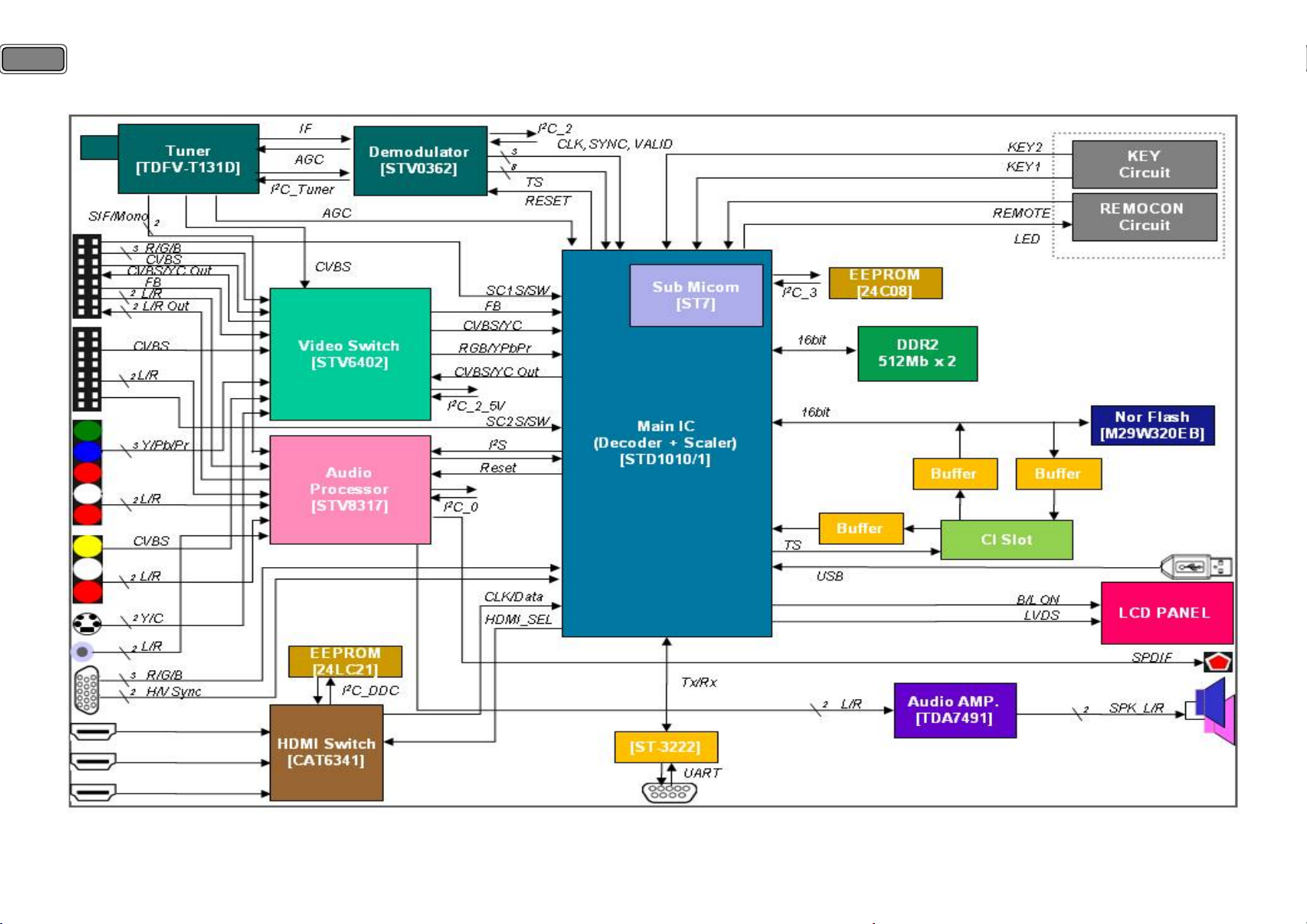
4. Block Diagram.
Page 11
5. Software Update.
5-1) Update using RS-232C cable.
5-1-1) Preparation.
① TV Set.
② Update Cable (RS-232C Cable).
③ IBM Compatible PC.
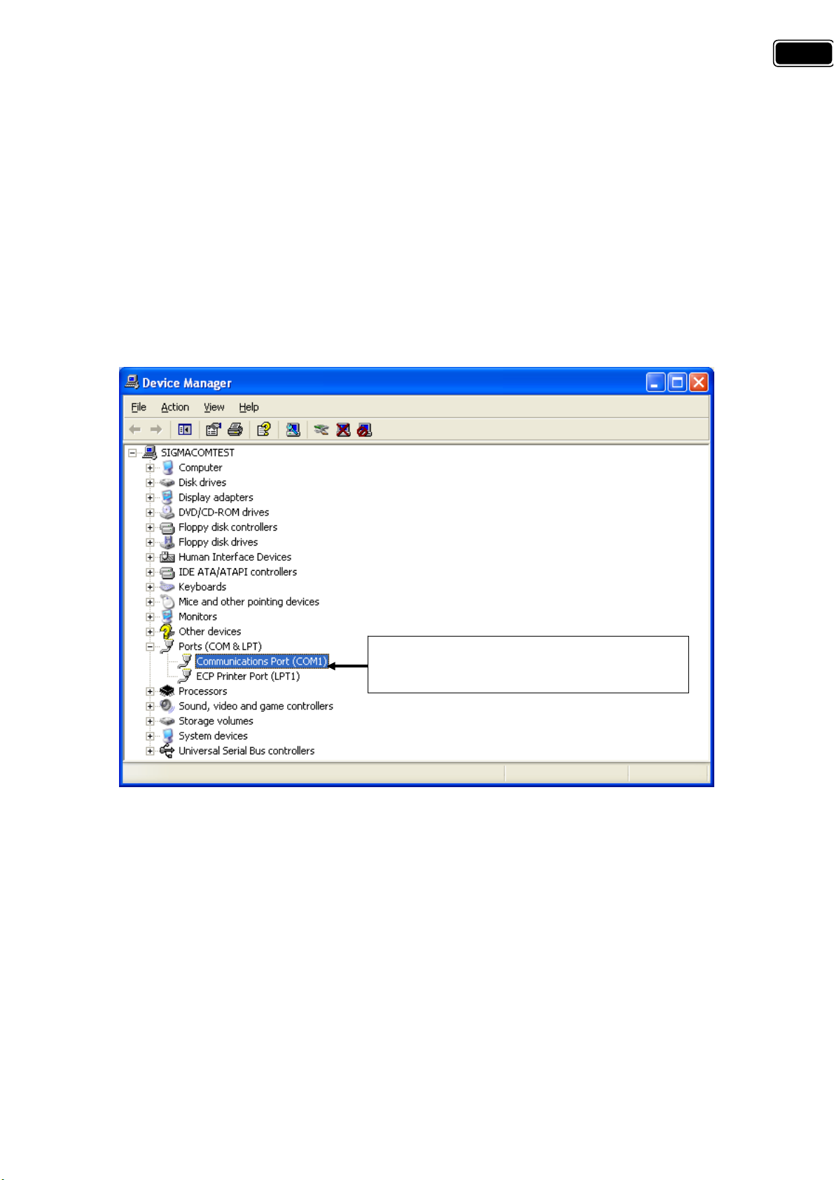
5-1-2) System Configuration.
PC Configuration.
All the configuration of Serial Port (COM1/COM2) should be done before proceed because the update requires
RS-232C port of PC.
11
Be sure Communication Port is installed
properly as seen on the figure.
If Communication (Serial) Port is not installed, check your CMOS (Computer System Menu) and activate Serial
Port in it.
5-1-3) Introduction.
A PC tool “Serial Flasher” is provided to update Magello software.
The PC tool must be started before starting up the board.
Page 12
12
5-1-4) Tool installation.
Uncompress the zip file provided in a working directory.
In this directory copy also the binary file (magello.bin) which will be used for the software update.
5-1-5) Procedure.
① Main power off the board.
② Connect a serial cable(RS-232C) between the board and the PC where the “Serial Flasher” is installed.
③ Check the new “magello.bin” is in the “Serial Flasher” directory.
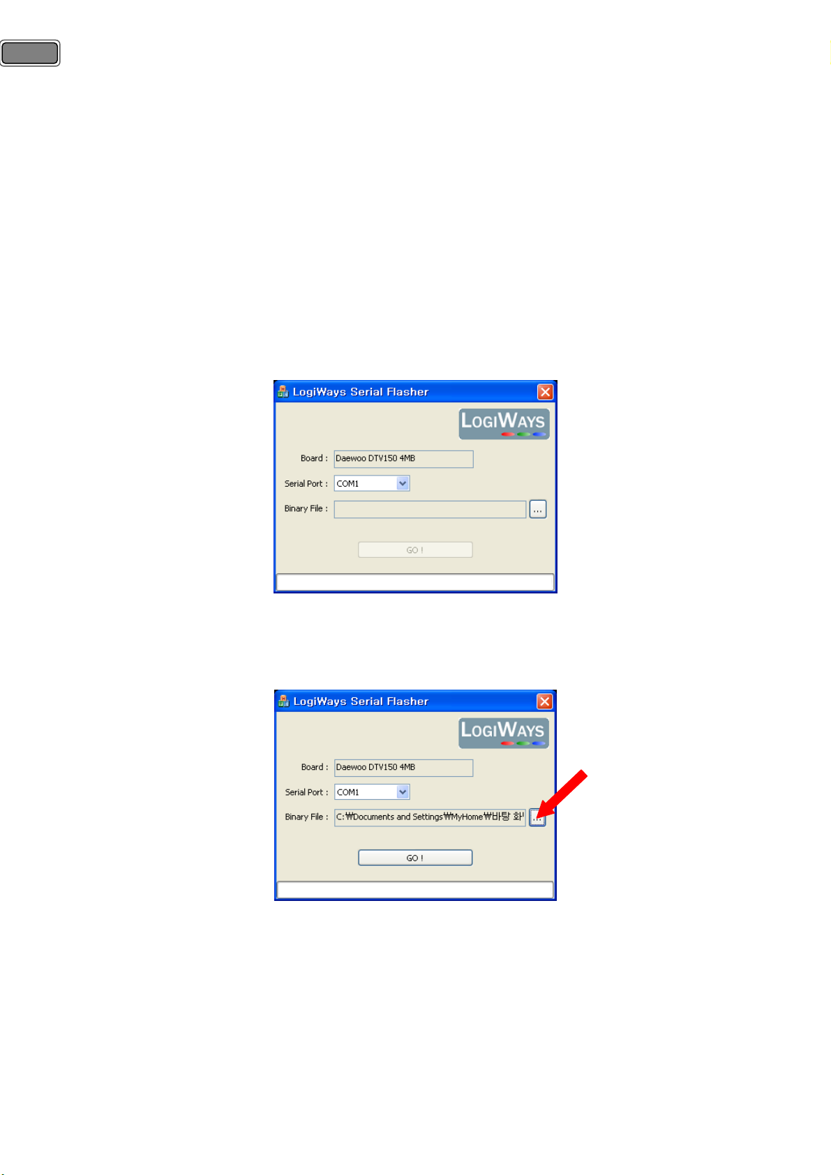
④ Start the PC Tool : LW Serial Flasher_Daewoo_IDTV.exe.
< Main screen of Serial flasher>
⑤ Use browse button “…” to select the new software for the upgrade (magello.bin).
<Serial flasher : New software selected>
⑥ Press “GO!” to start the connection process.
⑦ Power on the board.
⑧ Wait a few seconds for the connection process to start : The message : « Connecting board … » is displayed.
Page 13
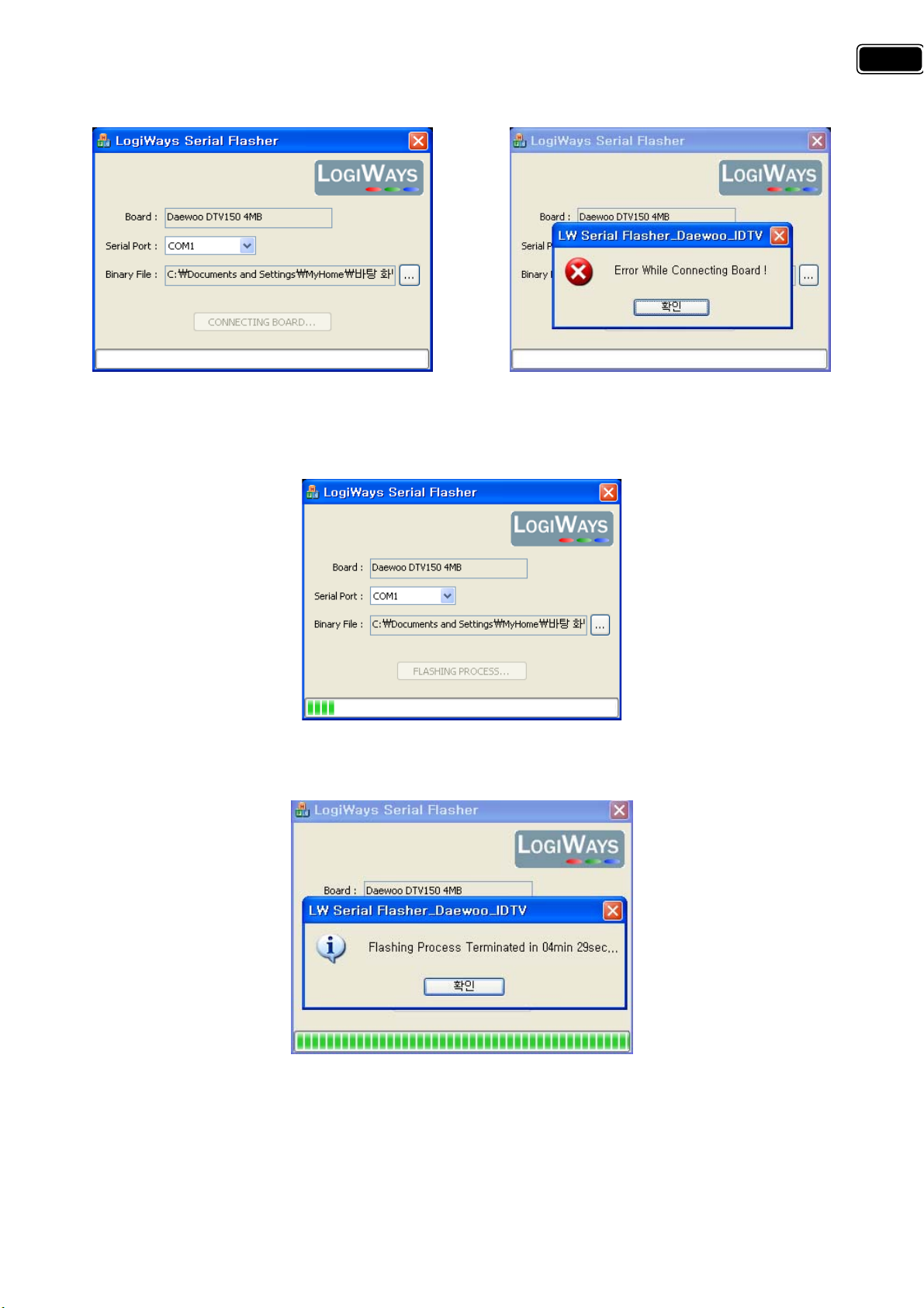
First of all, power of board should be turned on, as a normal operating mode, during update.
If error message is displayed, after turn off main power, check above ②. And then repeat from ① to ⑦.
<Connecting PC and Main Board> <When error message displayed>
13
<Processing Update>
<Update is completed>
⑨ After the main board is updated completely with the new software, turn off main power and then turn on.
⑩ After EEPROM reset in Factory mode(#6) should be done is ready to use.
Page 14
14
Key
Key
5-2) Upgrade using USB Memory.
1) Insert USB (contain xxx.bin file) and then USB Download Window appeared.
2) Select file to upgrade and press OK key.
3) TV set will turn off and upgrade automatically.
4) After about one minute, TV set will turn on automatically
6. Service mode.
6-1) Using the Service Remote controller.
: you can enter service mode directly and change default value using R-34SVC (S/N: 48B3034SVC) as a table.
Name Details Value
S1 Heat-Run
S2 Luma Chroma delay Default : 0 (For R&D engineer)
S3 Speaker Volume minimum->middle->maximum
S4
S5 Dot Pixel test BLACK Æ WHITE Æ RED Æ GREEN Æ BLUE
S6~S11
S12 Shipping Set up at shipping mode
6-2) Using the User Remote controller (S/N : 48B6360B01).
: you can also enter the factory mode by pressing Red, Green, and Menu Button continuously as a table.
Name Details Function
1
Inch Option
ST7 ESD For electric charge problem Default : On
Module Name DTV150EU
I2C Sleep Default : Off (For R&D engineer)
Color Temp Normal Æ Cold Æ Warm
R Drv Default : 50
G Drv Default : 52
Adjust white balance data
for each Panel
(Future Available)**
32 Æ 42 Æ Full 42 Æ 37 inch
(37”)
B Drv Default : 57
R Gain Default : 0
G Gain Default : 0
B Gain Default : 0
2 Same as S4
3 Source save Not used Default : Off (For R&D engineer)
Page 15
Key Name Details Function
g
Brightness Min Fix -128
Brightness Mid Fix 0
Brightness Max Fix 127
Contrast Min Fix 40
Contrast Mid Fix 111
Contrast Max Fix 182
Color Min Fix 0
Color Mid Fix 256
Color Max Fix 507
Sharpness Min Fix 0
4
Sharpness Mid Fix 18
Sharpness Max Fix 36
Tint Min Fix -32
Tint Mid Fix 0
Tint Max Fix 31
Picture Mode Fix CinemaÆNormalÆFavourite ÆDynamic
Brightness Fix 32
Color Fix 32
Sharpness Fix 32
Contrast Fix 58
Tint Fix 0
Level Prescale AM Fix 9
Nicam Prescale Fix 20
FM Prescale Fix 6
5
SCART Prescale Fix -1
Level Prescale I2S0 Fix -10
Level Prescale I2S1 Fix 8
Level Prescale I2S2 Fix 8
Level Prescale I2S3 Fix 8
Field Mode detection Picture quality (For R&D engineer)
6
EEPROM Reset Press OK key, EEPROM data erased and TV set reboot automatically
ST7 FW ST7 upgrade.
EDID Reset For update EDID data
White balance
Initial gamma correction &
7
Color Warpin
tuning
R.G.B & Gamma Testing item
Gamma correction check
RGB compliance check
8 Advanced setting Advanced Picture setting (For R&D engineer)
Hotel mode
Initial Input
9
Max Vol Level
Max PR.
Not ready. (For special purpose)
Local Key Lock
Remote Lock
15
(Normal)
Page 16
16
7. Hardware Trouble Shooting
7-1) No picture or picture with poor quality.
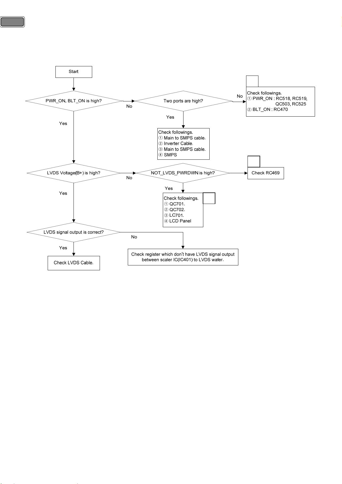
7-1-1) Back-light does not turn on and no LVDS signal.
A
B
C
A. Check RC470.
: RC470 is only one path from main chip(IC401) to SMPS. During power on, both sides of RC470 should be
high. If it is high and back light of LCD does not turn on, check as ‘Check followings’. If cables are no problem,
finally check SMPS. (see the page 36)
B. Check RC469
: RC469 is located between main chip(IC401) and transistor(QC701) for switch LCD panel power. During power
on, both sides of RC469 should be high. If it is high and LCD power is low, check as ‘Check followings’. If
QC701, QC702, LC701 are no problem, check LCD panel.
C. Details of Check followings.
-. QC701 : Transistor for switching LCD panel power.
-. QC702 : FET for driving LCD panel power.
-. LC701 : Coil for rectifying LCD panel power.
-. Registers between scaler IC(IC401) and LVDS wafer
① Only signal path : RC723 ~ RC743.
② Panel options. Æ see the page 49.
Page 17
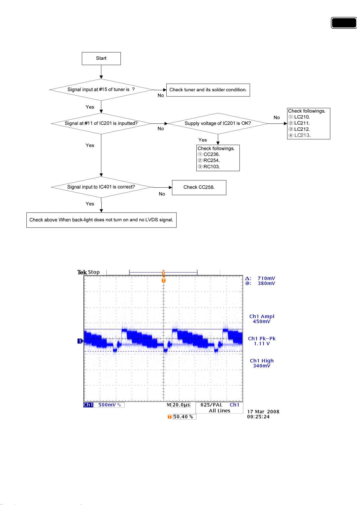
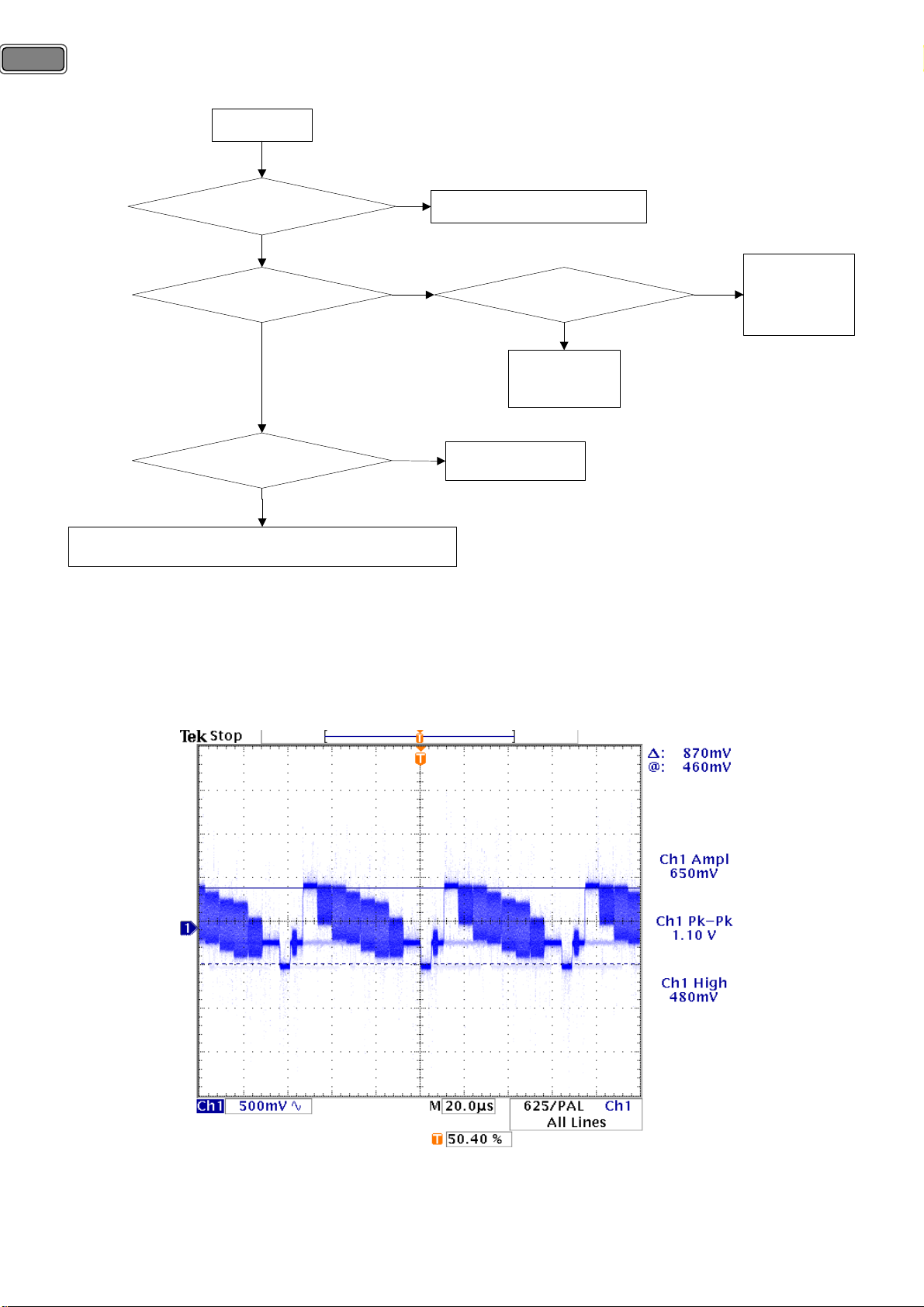
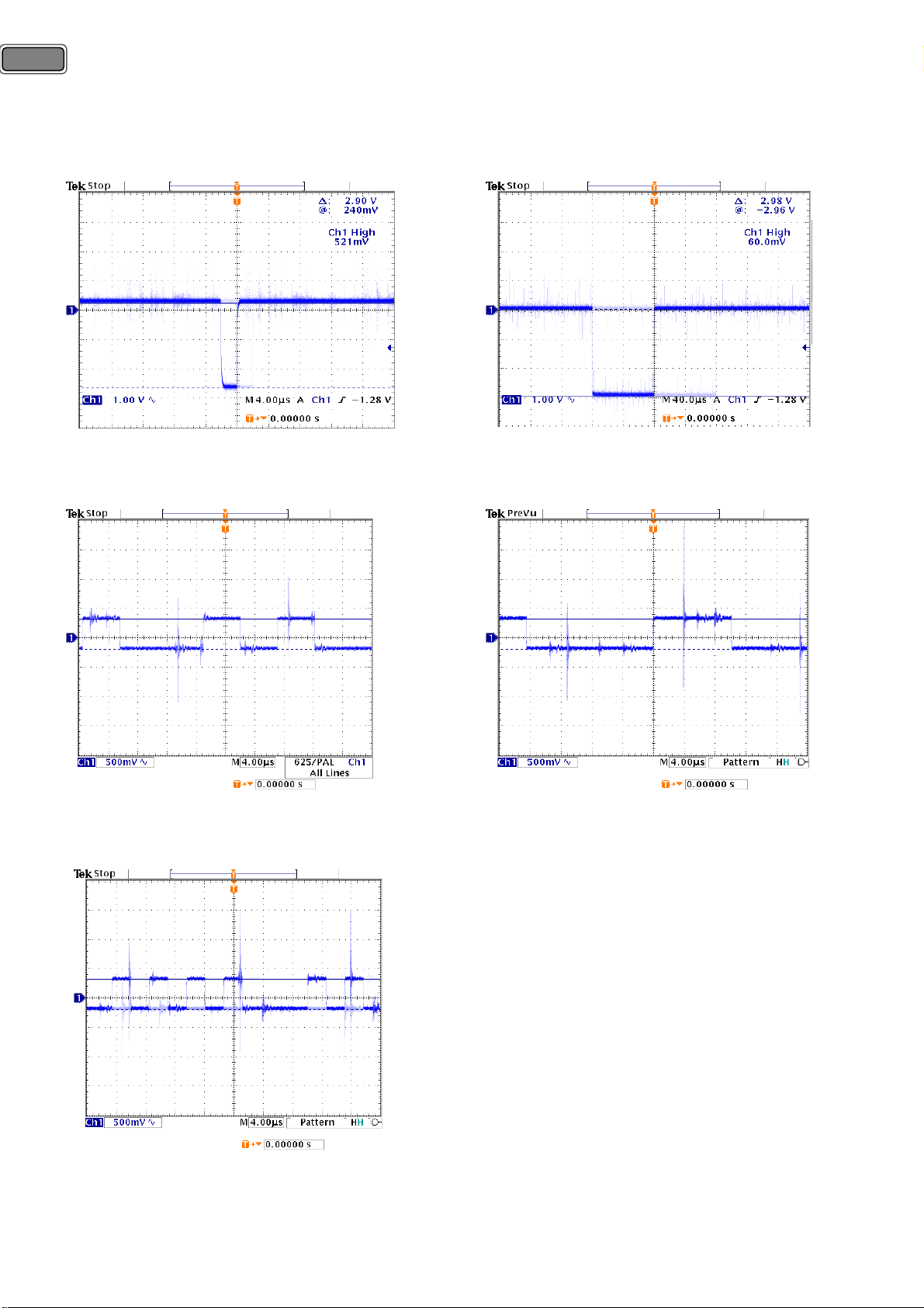
7-1-2) No Analog TV is displayed.
17
<Normal signal waveform>
Æ Mode : Analog TV, Pattern : Color Bar.
Page 18
18
7-1-3) No picture in CVBS of AV1 mode.
Start
Signal input at #20 of JK201 is ?
No
Yes
Signal at #63 of IC201 is inputted?
No
Yes
Signal input to IC401 is correct?
No
Yes
Check above When back-light does not turn on and no LVDS signal.
<Normal signal waveform>
Check JK201 and its solder condition.
Supply voltage of IC201 is OK?
Yes
Check followings.
① CC257.
② RC201.
Check CC258.
Check followings.
① LC210.
No
② LC211.
③ LC212.
④ LC213.
Æ Mode : AV1-CVBS, Pattern : COL_100/Fluke 54200.
Page 19
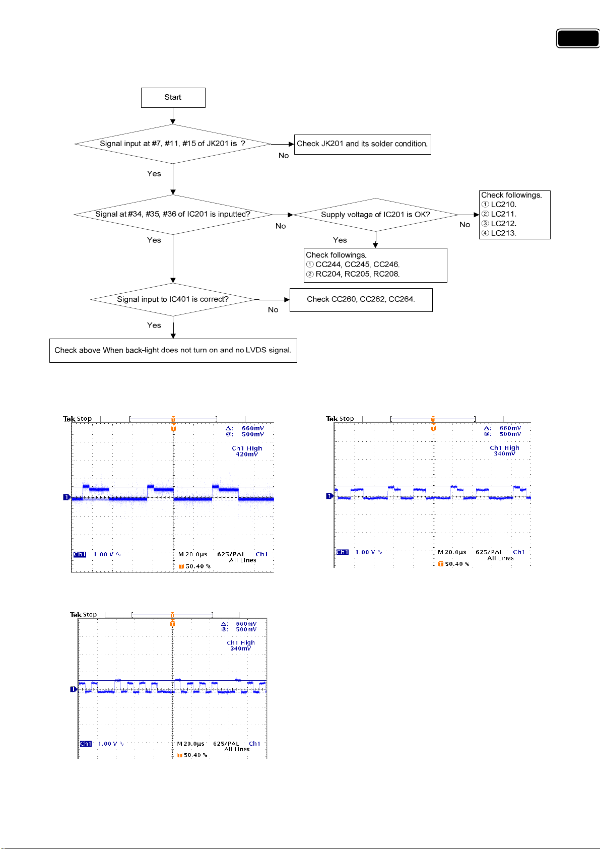
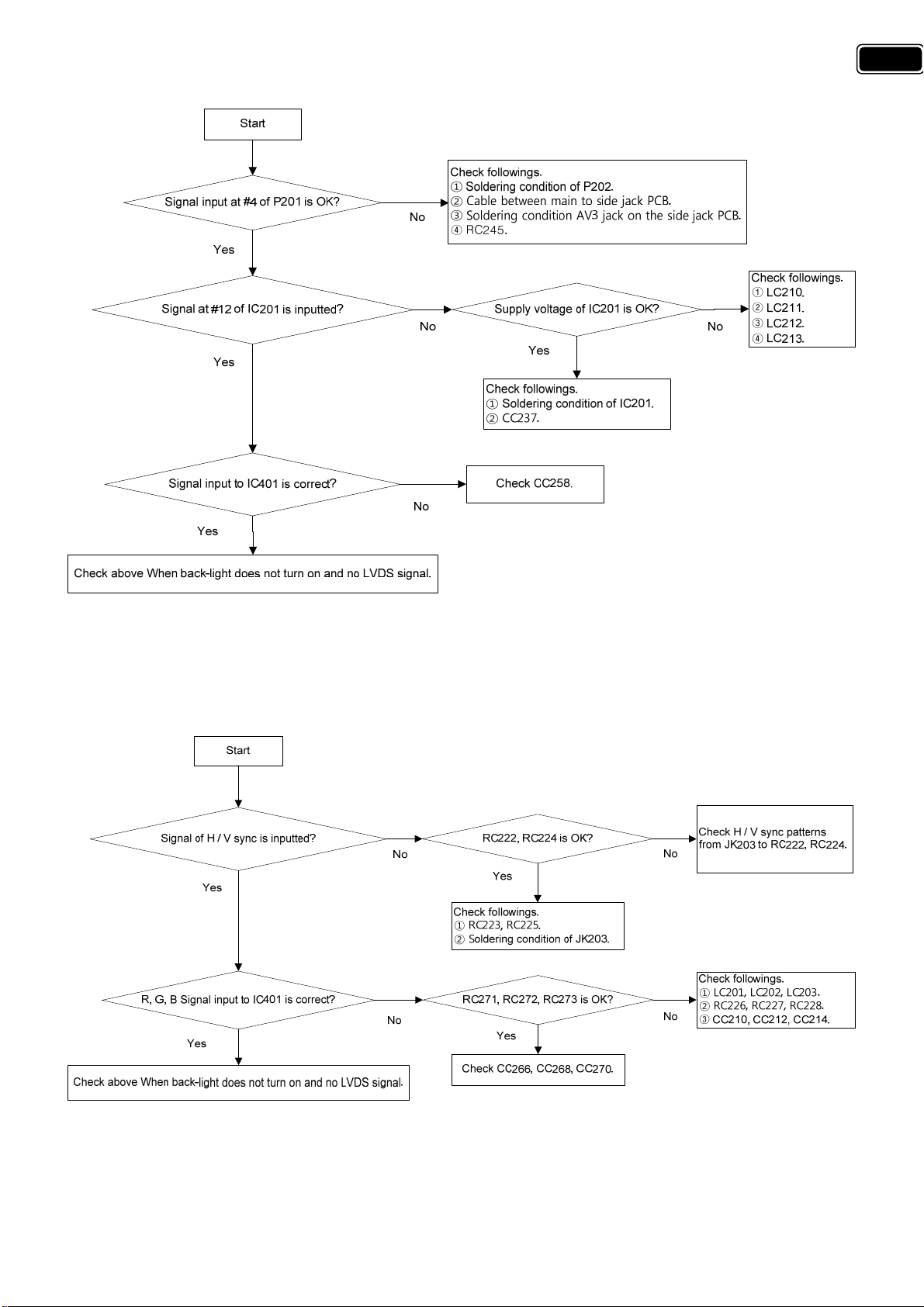
7-1-4) No picture in RGB of AV1 mode.
19
<Normal signal waveform>
Æ Mode : AV1-RGB, Pattern : COL_100/Fluke 54200.
SCART1 R SCART1 G
SCART1 B
Page 20
20
7-1-5) No picture in CVBS of AV2 mode.
Start
Signal input at #20 of JK202 is ?
Yes
Signal at #2 of IC201 is inputted?
Yes
Signal input to IC401 is correct?
Yes
Check above When back-light does not turn on and no LVDS signal.
Check JK202 and its solder condition.
No
No
No
<Normal signal waveform>
Æ Mode : AV2-CVBS, Pattern : COL_100/Fluke 54200.
Supply voltage of IC201 is OK?
Yes
Check followings.
① CC230.
② RC215.
Check CC258.
Check followings.
① LC210.
No
② LC211.
③ LC212.
④ LC213.
Page 21
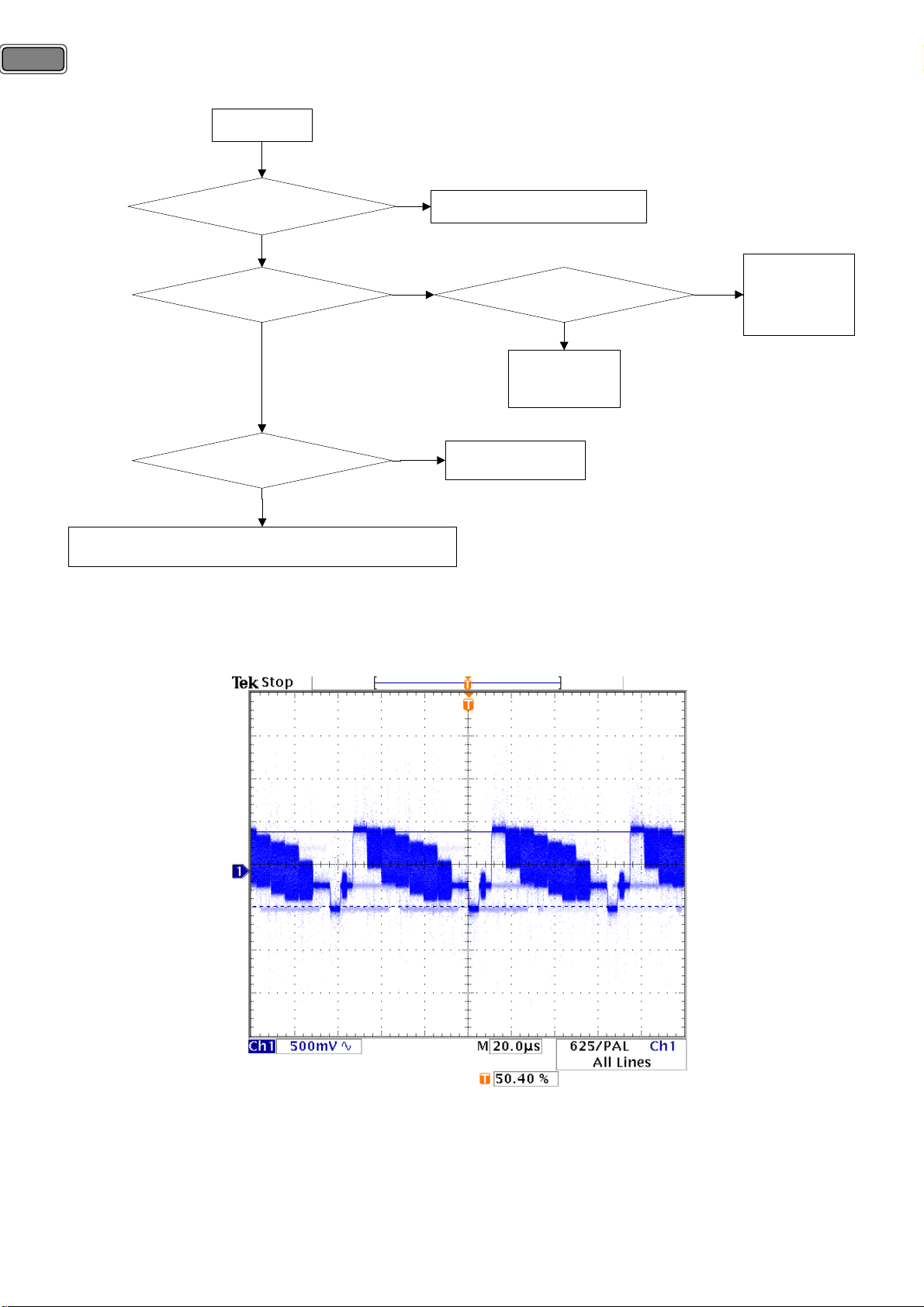
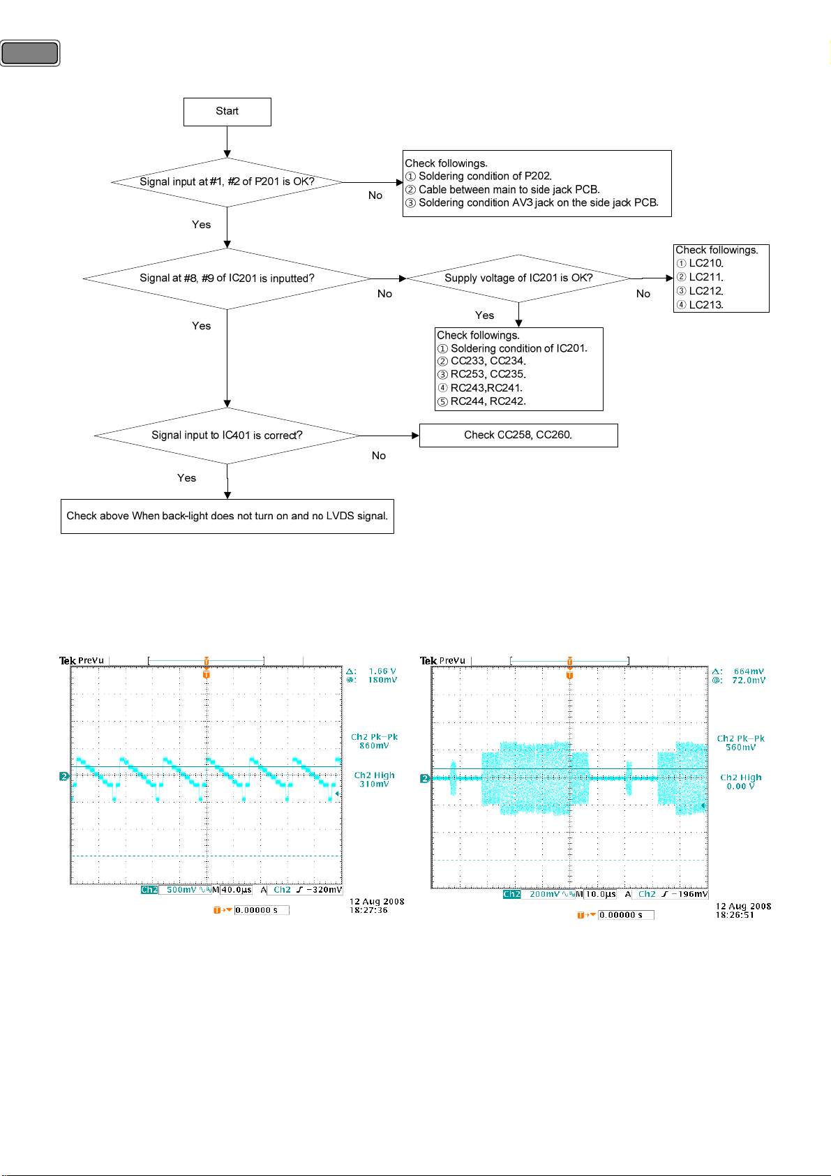
7-1-6) No picture in CVBS of AV3 mode.
21
Normal signal waveform is equal to CVBS of AV1 or AV2
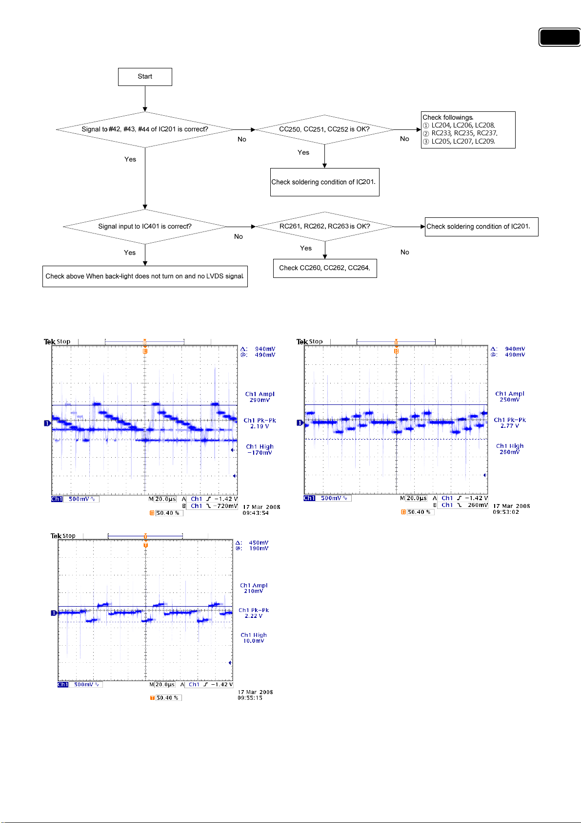
7-1-7) No picture in PC Mode.
Page 22
22
<Normal signal waveform>
Æ Mode : PC, Pattern : Color Bar / Pattern Generator.
PC_H Sync PC_V Sync
PC R
PC B
PC G
Page 23
7-1-8) No picture in component mode.
<Normal signal waveform>
Æ Mode : Component, Pattern : Full White/Fluke 54200.
23
COMPONENT Y COMPONENT P
COMPONENT Pr
b
Page 24
24
7-1-9) No picture in S-video mode.
<Normal signal waveform>
Æ Mode : S-Video, Pattern : Full White/Fluke 54200.
S-Video Y S-Video C
Page 25

7-1-10) No picture at external TV connected with AV1(RF-Output).
: Video switching IC(IC201) using internal channel-switching outputs RF output signal from AV1 in this TV to
external TV. So trouble shooting for RF output is very simple as a followings.
25
<Notes concerned with RF output>
① During watching TV in the HDMI mode, No digital TV sound to external TV is outputted. Because each
sound-port of HDMI and digital TV uses I
2
S. If one mode of digital TV or HDMI is selected, the other mode’s
sound does not output to external TV using RF output/TV OUT.
② This TV does not support RF output of digital radio channel.
③ This TV does not support RF output of Media mode.
<Normal signal waveform>
Æ Mode : RF Output, Pattern : Color Bar / Analog TV
Page 26

26
7-1-11) No picture/Sound in HDMI mode.
This TV has a high-performance 3-port-to-1-port HDMI active switch. A current one-port HDMI Sink system
could be easily upgraded to three-port by adding a switch, as a following. Source selection is done by
controlling the pins S1, S2 and S3. The selected HDMI input port is activated and the associated signals are
routed to the output port.
Page 27

7-2) When no sound output from internal speaker.
7-2-1) No sound of analog TV mode.
27
1) A. Check soldering condition of SIF pin.
: If power and solder-condition of tuner are no problem, signal of tuner should be outputted at a channel.
Check soldering condition of SIF pin.
2) Check followings.
① Re-solder CC634, CC635 : Capacitors for decoupling and noise reduction.
3) Check followings.
① LC608 : Coil for noise reduction
② RC620 : Register for divide
③ Supply voltage of IC602 : Check LC611, LC612 for 1.8V, LC613, LC614 for 3.3V, LC615 for 8V .
4) Re-solder LC609, LC610 : Coil for noise reduction
5) Check CC665, CC666 : Capacitors for noise reduction.
Page 28

28
7-2-2) No sound of AV1 mode.
1) Check soldering condition of JK201, AV1.
2) Check followings.
① RC211, RC214 : Registers are located between JK201 and CC644, CC645.
② ZA202, ZA204 : ESD protectors are located between resisters above ‘① RC211, RC214’ and CC644, CC645.
③ RC209, RC213 : Registers for dividing.
3) The rests is the same as above 1) No sound of analog TV mode.
Page 29

7-2-3) No sound of AV2 mode.
29
1) Check soldering condition of JK202, AV2.
2) Check followings.
① RC219, RC221 : Registers are located between JK201 and CC644, CC645.
② ZA205, ZA206 : ESD protectors are located between resisters above ‘① RC219, RC221’ and CC644, CC645.
③ RC218, RC220 : Registers for dividing.
3) The rest is the same as above 1) No sound of analog TV mode.
Page 30

30
7-2-4) No sound of PC/DVI Sound mode.
Start
Sound input is OK?
( #2, #4 of JK204)
Yes
Input to #19, #20 of IC602 is OK?
Yes
Output from #34, #36 of IC602 is OK?
Yes
See the page of Sound In/Output of AMP
No
No
No
Check soldering condition of JK204.
CC654, CC655 is OK?
Yes
Check followings.
① Soldering condition of IC602.
② Power of IC602.
LC609, LC610 is OK?
Yes
Check CC665, CC666.
No
No
Check followings.
① ZA207, ZA208.
② RC229, RC230.
Re-solder LC609, LC610.
1) Check soldering condition of JK204.
2) Check followings.
① ZA205, ZA206 : ESD protectors are located from JK204 to each of CC644, CC645.
② RC218, RC220 : Registers for dividing.
3) The rest is the same as above 1) No sound of analog TV mode.
Page 31

7-2-5) No sound of Component Sound mode.
Start
31
Sound input is OK?
( #11, #14 of JK205-B)
Yes
Input to #99, #100 of IC602 is OK?
Yes
Output from #34, #36 of IC602 is OK?
Yes
See the page of Sound In/Output of AMP
No
No
No
Check soldering condition of JK205-B.
CC636, CC637 is OK?
Yes
Check followings.
① Soldering condition of IC602.
② Power of IC602.
LC609, LC610 is OK?
Yes
Check CC665, CC666.
No
No
Check followings.
① ZA209, ZA210.
② RC231, RC232.
Re-solder LC609, LC610.
1) Check soldering condition of JK205-B.
2) Check followings.
① ZA209, ZA210 : ESD protectors are located from JK204 to each of CC644, CC645.
② RC231, RC232 : Registers for dividing.
3) The rest is the same as above 1) No sound of analog TV mode.
Page 32

32
7-2-6) No sound of AV3/S-Video Sound mode.
Start
Check followings.
Sound input is OK?
( #6, #8 of P202)
Yes
Input to #28, #29 of IC602 is OK?
Yes
① Soldering condition of P202.
② Cable between main to side jack PCB.
③ Soldering condition S-video and AV3 jack on the side jack PCB.
No
④ RC908, RC909.
No
CC659, CC660 is OK?
Yes
Check followings.
① Soldering condition of IC602.
② Power of IC602.
No
Check followings.
① RC247, RC249.
② ZA211, ZA212.
③ RC248, RC250.
Output from #99, #100 of IC602 is OK?
No
Yes
See the page of Sound In/Output of AMP
LC609, LC610 is OK?
No
Yes
Check CC665, CC666.
1) Check followings.
① Soldering condition of P202. : Connector wafer for connecting side jack PCB(Union).
② Cable between main to side jack PCB.
③ Soldering condition S-video and AV3 jack on the side jack PCB.
④ RC908, RC909.
2) Check followings.
① RC247, RC249.
② ZA211, ZA212. : ESD protectors are located from JK204 to each of CC644, CC645.
Re-solder LC609, LC610.
③ RC248, RC250. : Registers for dividing.
3) The rest is the same as above 1) No sound of analog TV mode.
Page 33

7-2-7) No sound of Digital TV/HDMI mode.
2
: The sound of Digital TV and HDMI mode use I
Start
Input to #76~#81 of IC602 is OK?
No
S. I2S ports are consisting of Data, Clock lines.
RC126~RC131 are OK?
Yes
Check followings.
No
① Re-solder registers which have problems.
② IC401 revolving.
33
Yes
Output from #99, #100 of IC602 is OK?
No
Yes
See the page of Sound In/Output of AMP
Check followings.
① Soldering condition of IC602.
②Supply voltage of IC602.
LC609, LC610 is OK?
Yes
Check CC665, CC666.
Re-solder LC609, LC610.
No
1) Check followings.
① Re-solder registers which has a problem. : Data, Clock lines.
② IC401 revolving. : If soldering condition of registers is OK, no signal from IC401 is outputted.
2) The rest is the same as above 1) No sound of analog TV mode.
7-2-8) No sound at external TV connected with AV1(RF-Output).
Page 34

34
7-2-9) No Picture or No Sound In the Media(USB) Mode.
Start
Signal at LC311 is inputted?
Yes
Signal input of JK304 is OK?
Yes
No
No
Check followings.
① Soldering condition of JK304, JK903.
② 4-pin cable between main to side jack PCB.
Supply voltage is OK?
Yes
Check followings.
① Soldering condition of IC304.
② Transistors QC306 QC307.
No
Check followings.
① RC338, RC343, LC310 for 3.3V.
② LC309 for 2.5V.
③ LC314 for 5V.
④LC213.
Signal input to IC401 is correct?
Yes
Check above When back-light does not turn on and no LVDS signal
and
See the page of Sound In/Output of AMP.
7-2-10) Sound In/Output of AMP.
Start
Hardware reset is OK?
Yes
Supply voltage of IC601 is OK?
Yes
No
No
No
Check CC258, CC260.
Check followings.
① #2 of IC603 for 3.3V
② RC601of Mute control port.
③ Switching transistor QC601.
Check followings.
① RC603, RC608, RC672 for 3.3V
② #6, #7, #12, #13 of IC601 for 15V.
Signals at #22, #32 of IC601 are inputted ?
Yes
Signal to P601, P602 is outputted?
Yes
Check Speaker Assembly
And Speaker Cable.
Check followings.
① Sound output depending on mode, refer to above.
② CC601, CC602, CC607, CC608.
No
Check followings.
① PWM Signal : Sound output of #2, #3, #6, #7, #8, #9,
#10, #11, #12, #13, #16, #17 of IC601.
No
② Wave : P601, P602
Page 35

7-3. When supply voltage of SMPS is not good.
7-3-1) 32, 37 inch Model (FEL-3237VN).
1 . Stand-by 5V is working out.
A. Can you check In-put voltage(DC390V) of the capacitor(Location No. :C9)?
A. Can you check that Vcc voltage of IC1 was supplied from DC13V to DC16V?
YES 1.1 Checking open and short of Out-put side wire cable.
YES
NO
NO
2. MAIN Out-put voltage is working out but Stand-by 5V is working.
A. Is Power On signal(1V) supplied to Base of CQ6?
B. Can you check the CQ6's condition(open and short)?
NO
YES
NO 2.7. Checking open and short of MAIN BORD.
3. 5V's Out-put voltage is measured too high or low.
A. Checking open and short of IC5.
B. Checking open and short of CR30,CR31.
C. Checking open and short of IC3.
4. 5V's Out-put voltage is work with intermittent mode.
A. Is R7's condition good from open and short?
YES: changing R7. NO: Checking 1.3 and 1.4 items.
(Checking open and short of MAIN BORD if that 1,3 and 1.4 items are no problem.)
5. Out-put voltage(DC12V,15V,24V) is measured too high.
A. Checking open and short of CR38,CR39,CR40,CR41,CR42.
B. Checking open and short of IC2
6. Out-put voltage(DC12V,15V, 24V) is measured too low.
A. Checking open and short of CR38,CR39,CR40,CR41,CR42.
B. Checking open and short of IC2
YES 2.4. changing CQ6.
C. Can you check that Vcc voltage of IC2's No.15pin was supplied from DC12V to DC16V?
NO
YES 2.6. Checking open and short of MAIN BORD.
1.2. Checking open and short of the around parts that was connected IC1(CM6807).
(Location No. :Q5,R7,CQ1,CQ2,CQ3,CQ4,CQ9,Q1,CD2,CD3,IC4,R4,D2)
1.3. Checking open and short of IC1's each pins.
1.4. Checking open and short of 5V's Out-put diode.
1.5. Can you check the Fuse(F1) condition(open and short)?
YES : Checking 1.2 item after changing FUSE. NO : Checking 1.6 item
1.6. Checking open and short of BD1.
YES: Changing BD1.
NO: Checking open and short of Z1,LF1,LF2 ,C1,C2 ,R1
2.1. Can you check the CQ5's condition(open and short)?
YES: Changing CQ5. NO: Checking 2.2 item.
2.2. Can you check the IC4's condition(open and short)?
YES: Changing IC4. NO: Checking 2.3 item.
2.3. Can check the voltage(DC 390V) of AC rectifying side C9?
YES: Checking 2.5 item.
NO: Checking 1.2 item.
2.5. Can you see the square wave(400mV, 50kH) of CQ16's GATE(A,B) side when DC 18V
was supplied to D4's No.(-)pin from DC POWER SUPPLY?
(CAUTION : Test do it after AC Power Off)
YES: Checking 2.1 item after checking diode's condition(open and short) of Main
Out-put side. (Location No. :D6,D7,D9)
NO: Checking open and short of the around parts that was connected IC2.
(Location No. :CQ15,CQ16,CQ11,CQ12,CQ13,CQ14,CD4,CD5,CD6,Q4,Q3,IC2)
35
Page 36

36
7-3-2) 42 inch Models (FEL-4247VN).
1 . Stand-by 5V is working out.
A. Can you check In-put voltage(DC390V) of the capacitor(Location No. :C9)?
A. Can you check that Vcc voltage of IC1 was supplied from DC13V to DC16V?
YES 1.1 Checking open and short of Out-put side wire cable.
YES
NO
2. MAIN Out-put voltage is working out but Stand-by 5V is working.
A. Is Power On signal(1V) supplied to Base of CQ6?
B. Can you check the CQ6's condition(open and short)?
YES
3. 5V's Out-put voltage is measured too high or low.
A. Checking open and short of IC5.
B. Checking open and short of CR30,CR31.
C. Checking open and short of IC3.
4. 5V's Out-put voltage is work with intermittent mode.
A. Is R7's condition good from open and short?
YES: changing R7. NO: Checking 1.3 and 1.4 items.
(Checking open and short of MAIN BORD if that 1,3 and 1.4 items are no problem.)
5. Out-put voltage(DC12V,15V,24V) is measured too high.
A. Checking open and short of CR38,CR39,CR40,CR41,CR42.
B. Checking open and short of IC2
6. Out-put voltage(DC12V, 15V, 24V) is measured too low.
A. Checking open and short of CR38,CR39,CR40,CR41,CR42.
B. Checking open and short of IC2
C. Can you check that Vcc voltage of IC2's No.15pin was supplied from DC12V to DC16V?
NO 2.7. Checking open and short of MAIN BORD.
1.2. Checking open and short of the around parts that was connected IC1(CM6807).
(Location No. :Q5,R7,CQ1,CQ2,CQ3,CQ4,CQ9,Q1,CD2,CD3,IC4,R4,D2)
NO
1.3. Checking open and short of IC1's each pins.
1.4. Checking open and short of 5V's Out-put diode.
1.5. Can you check the Fuse(F1) condition(open and short)?
YES : Checking 1.2 item after changing FUSE. NO:Checking 1.6 item
1.6. Checking open and short of BD1.
YES: Changing BD1.
NO: Checking open and short of Z1,LF1,LF2 ,C1,C2,R1
2.1. Can you check the CQ5's condition(open and short)?
YES: Changing CQ5. NO: Checking 2.2 item.
2.2. Can you check the IC4's condition(open and short)?
YES: Changing IC4. NO: Checking 2.3 item.
NO
2.3. Can check the voltage(DC 390V) of AC rectifying side C9?
YES: Checking 2.5 item.
NO: Checking 1.2 item.
YES 2.4. changing CQ6.
2.5. Can you see the square wave(400mV, 50kH) of CQ16's GATE(A,B) side when DC 18V
was supplied to D4's No.(-)pin from DC POWER SUPPLY?
(CAUTION : Test do it after AC Power Off)
YES: Checking 2.1 item after checking FET's condition(open and short) of Main
NO
Out-put side. (Location No. :Q6,CQ16,CQ17)
NO: Checking open and short of the around parts that was connected IC2.
(Location No. :CQ15,CQ16,CQ17,CQ11,CQ7,CQ8,CQ9,CQ10,CQ11,
CQ12,CQ13,CQ14,CD4,CD5,CD6,Q4,,Q6,Q3,IC2)
YES 2.6. Checking open and short of MAIN BORD.
Page 37

8. Parts List.
8-1. Main Board Part List.
Loc. Part Name Part Description Loc. Part Name Part Description
A001 PCB MAIN 234X189 K4V CC151 C CHIP 50V Y5V 0.1MF Z 1608
CC1 C CHIP 50V Y5V 0.1MF Z 1608 CC152 C CHIP 50V Y5V 0.1MF Z 1608
CC101 C CHIP 50V CH 100PF J 1608 CC153 C CHIP 50V Y5V 0.1MF Z 1608
CC102 C CHIP 50V Y5V 0.1MF Z 1608 CC154 C CHIP 50V Y5V 0.1MF Z 1608
CC103 C CHIP 50V CH 100PF J 1608 CC2 C CHIP 50V X7R 0.01MF K 1608
CC104 C CHIP 50V CH 100PF J 1608 CC200 C CHIP 50V Y5V 0.1MF Z 1608
CC105 C CHIP 50V Y5V 0.1MF Z 1608 CC201 C CHIP 50V X7R 1500PF K 1608
CC106 C CHIP 50V CH 100PF J 1608 CC202 C CHIP 50V X7R 6800PF K 1608
CC107 C CHIP 50V CH 100PF J 1608 CC203 C CHIP 50V X7R 6800PF K 1608
CC108 C CHIP 50V Y5V 0.1MF Z 1608 CC204 C CHIP 50V X7R 1500PF K 1608
CC109 C CHIP 50V CH 100PF J 1608 CC205 C CHIP 50V Y5V 0.1MF Z 1608
CC110 C CHIP 50V Y5V 0.1MF Z 1608 CC206 C CHIP 50V X7R 1500PF K 1608
CC111 C CHIP 50V CH 100PF J 1608 CC207 C CHIP 50V X7R 1500PF K 1608
CC112 C CHIP 50V Y5V 0.1MF Z 1608 CC211 C CHIP 50V CH 10PF J 1608
CC113 C CHIP 50V Y5V 0.1MF Z 1608 CC213 C CHIP 50V CH 10PF J 1608
CC114 C CHIP 50V CH 330PF J 1608 CC215 C CHIP 50V CH 10PF J 1608
CC115 C CHIP 50V CH 100PF J 1608 CC216 C CHIP 50V X7R 1500PF K 1608
CC116 C CHIP 50V Y5V 0.1MF Z 1608 CC217 C CHIP 50V X7R 1500PF K 1608
CC117 C CHIP 50V CH 100PF J 1608 CC218 C CHIP 50V X7R 1500PF K 1608
CC118 C CHIP 50V Y5V 0.1MF Z 1608 CC219 C CHIP 50V X7R 1500PF K 1608
CC119 C CHIP 50V CH 100PF J 1608 CC224 C CHIP 50V CH 1000PF J 1608
CC120 C CHIP 50V CH 100PF J 1608 CC225 C CHIP 50V CH 1000PF J 1608
CC121 C CHIP 50V CH 100PF J 1608 CC230 C CHIP 10V X7R 1MF K 1608
CC122 C CHIP 50V Y5V 0.1MF Z 1608 CC231 C CHIP 50V X7R 0.047MF K 1608
CC123 C CHIP 50V CH 100PF J 1608 CC232 C CHIP 50V X7R 0.047MF K 1608
CC124 C CHIP 50V CH 100PF J 1608 CC233 C CHIP 10V X7R 1MF K 1608
CC125 C CHIP 50V Y5V 0.1MF Z 1608 CC234 C CHIP 50V X7R 0.047MF K 1608
CC126 C CHIP Y5V 10V 1MF Z 1608 CC235 C CHIP 50V Y5V 0.1MF Z 1608
CC127 C CHIP Y5V 10V 1MF Z 1608 CC236 C CHIP 10V X7R 1MF K 1608
CC128 C CHIP 50V Y5V 0.1MF Z 1608 CC237 C CHIP 10V X7R 1MF K 1608
CC129 C CHIP 50V Y5V 0.1MF Z 1608 CC238 C CHIP 10V X7R 1MF K 1608
CC130 C CHIP 50V CH 100PF J 1608 CC239 C CHIP 50V CH 100PF J 1608
CC131 C CHIP 50V CH 100PF J 1608 CC240 C CHIP 50V CH 100PF J 1608
CC132 C CHIP 50V CH 15PF J 1608 CC241 C CHIP 50V Y5V 0.1MF Z 1608
CC133 C CHIP 50V CH 15PF J 1608 CC242 C CHIP 50V Y5V 0.1MF Z 1608
CC134 C CHIP 50V Y5V 0.1MF Z 1608 CC243 C CHIP 50V Y5V 0.1MF Z 1608
CC135 C CHIP 50V Y5V 0.1MF Z 1608 CC244 C CHIP 10V X7R 1MF K 1608
CC138 C CHIP 50V Y5V 0.1MF Z 1608 CC245 C CHIP 10V X7R 1MF K 1608
CC246 C CHIP 10V X7R 1MF K 1608 CC403 C CHIP 50V Y5V 0.1MF Z 1608
CC250 C CHIP 10V X7R 1MF K 1608 CC404 C CHIP 50V Y5V 0.1MF Z 1608
CC251 C CHIP 6.3V Y5V 4.7MF Z 1608 CC405 C CHIP 50V Y5V 0.1MF Z 1608
CC252 C CHIP 6.3V Y5V 4.7MF Z 1608 CC408 C CHIP 50V CH 22PF J 1608
CC253 C CHIP 50V Y5V 0.1MF Z 1608 CC409 C CHIP 50V CH 22PF J 1608
37
Page 38

38
Loc. Part Name Part Description Loc. Part Name Part Description
CC254 C CHIP 50V Y5V 0.1MF Z 1608 CC410 C CHIP 50V Y5V 0.1MF Z 1608
CC255 C CHIP 50V Y5V 0.1MF Z 1608 CC411 C CHIP Y5V 16V 0.47MF Z 1608
CC256 C CHIP 50V Y5V 0.1MF Z 1608 CC412 C CHIP 50V CH 1000PF J 1608
CC257 C CHIP 10V X7R 1MF K 1608 CC413 C CHIP 50V Y5V 0.1MF Z 1608
CC258 C CHIP 50V X7R 0.022MF K 1608 CC414 C CHIP 50V CH 1000PF J 1608
CC259 C CHIP 50V X7R 0.022MF K 1608 CC415 C CHIP Y5V 16V 0.47MF Z 1608
CC260 C CHIP 50V Y5V 0.1MF Z 1608 CC416 C CHIP 50V Y5V 0.1MF Z 1608
CC261 C CHIP 50V Y5V 0.1MF Z 1608 CC417 C CHIP Y5V 16V 0.47MF Z 1608
CC262 C CHIP 50V Y5V 0.1MF Z 1608 CC418 C CHIP Y5V 16V 0.47MF Z 1608
CC263 C CHIP 50V Y5V 0.1MF Z 1608 CC419 C CHIP 50V CH 1000PF J 1608
CC264 C CHIP 50V Y5V 0.1MF Z 1608 CC420 C CHIP 50V Y5V 0.1MF Z 1608
CC265 C CHIP 50V Y5V 0.1MF Z 1608 CC421 C CHIP Y5V 16V 0.47MF Z 1608
CC266 C CHIP 50V Y5V 0.1MF Z 1608 CC422 C CHIP 50V CH 330PF J 1608
CC267 C CHIP 50V Y5V 0.1MF Z 1608 CC423 C CHIP 50V Y5V 0.1MF Z 1608
CC268 C CHIP 50V Y5V 0.1MF Z 1608 CC424 C CHIP 50V CH 330PF J 1608
CC269 C CHIP 50V Y5V 0.1MF Z 1608 CC429 C CHIP Y5V 16V 0.47MF Z 1608
CC270 C CHIP 50V Y5V 0.1MF Z 1608 CC430 C CHIP 50V CH 1000PF J 1608
CC271 C CHIP 50V Y5V 0.1MF Z 1608 CC431 C CHIP 50V Y5V 0.1MF Z 1608
CC3 C CHIP 50V Y5V 0.1MF Z 1608 CC434 C CHIP 50V Y5V 0.1MF Z 1608
CC303 C CHIP 50V Y5V 0.1MF Z 1608 CC435 C CHIP Y5V 16V 0.47MF Z 1608
CC304 C CHIP 50V Y5V 0.1MF Z 1608 CC436 C CHIP 50V CH 1000PF J 1608
CC305 C CHIP 50V CH 330PF J 1608 CC439 C CHIP Y5V 16V 0.47MF Z 1608
CC306 C CHIP 50V Y5V 0.1MF Z 1608 CC440 C CHIP 50V CH 1000PF J 1608
CC307 C CHIP 50V CH 330PF J 1608 CC445 C CHIP 50V X7R 0.01MF K 1608
CC310 C CHIP 50V Y5V 0.1MF Z 1608 CC450 C CHIP 50V Y5V 0.1MF Z 1608
CC312 C CHIP 50V Y5V 0.1MF Z 1608 CC451 C CHIP 50V Y5V 0.1MF Z 1608
CC313 C CHIP 50V Y5V 0.1MF Z 1608 CC452 C CHIP 50V Y5V 0.1MF Z 1608
CC316 C CHIP 50V Y5V 0.1MF Z 1608 CC453 C CHIP 50V Y5V 0.1MF Z 1608
CC319 C CHIP 50V Y5V 0.1MF Z 1608 CC454 C CHIP 50V Y5V 0.1MF Z 1608
CC322 C CHIP 50V Y5V 0.1MF Z 1608 CC455 C CHIP 50V CH 100PF J 1608
CC325 C CHIP 50V Y5V 0.1MF Z 1608 CC456 C CHIP 50V Y5V 0.1MF Z 1608
CC328 C CHIP 50V Y5V 0.1MF Z 1608 CC457 C CHIP 50V Y5V 0.1MF Z 1608
CC331 C CHIP 50V Y5V 0.1MF Z 1608 CC5 C CHIP 50V Y5V 0.1MF Z 1608
CC334 C CHIP 50V Y5V 0.1MF Z 1608 CC501 C CHIP 50V CH 18PF J 1608
CC337 C CHIP 50V Y5V 0.1MF Z 1608 CC502 C CHIP 50V CH 18PF J 1608
CC340 C CHIP 50V Y5V 0.1MF Z 1608 CC503 C CHIP 50V Y5V 0.1MF Z 1608
CC341 C CHIP 50V Y5V 0.1MF Z 1608 CC504 C CHIP 50V Y5V 0.1MF Z 1608
CC4 C CHIP 50V Y5V 0.1MF Z 1608 CC550 C CHIP 50V Y5V 0.1MF Z 1608
CC401 C CHIP 50V Y5V 0.1MF Z 1608 CC551 C CHIP 50V Y5V 0.1MF Z 1608
CC402 C CHIP 50V Y5V 0.1MF Z 1608 CC552 C CHIP 50V CH 330PF J 1608
CC553 C CHIP 50V Y5V 0.1MF Z 1608 CC613 C CHIP 50V Y5V 0.1MF Z 1608
CC554 C CHIP 50V CH 330PF J 1608 CC614 C CHIP 50V CH 330PF J 1608
CC555 C CHIP 50V Y5V 0.1MF Z 1608 CC615 C CHIP Y5V 16V 0.47MF Z 1608
CC556 C CHIP 50V CH 330PF J 1608 CC616 C CHIP 50V Y5V 0.1MF Z 1608
CC557 C CHIP 50V Y5V 0.1MF Z 1608 CC617 C CHIP 50V Y5V 0.1MF Z 1608
CC558 C CHIP 50V CH 330PF J 1608 CC618 C CHIP 50V Y5V 0.1MF Z 1608
Page 39

Loc. Part Name Part Description Loc. Part Name Part Description
CC559 C CHIP 50V Y5V 0.1MF Z 1608 CC619 C CHIP 50V CH 330PF J 1608
CC560 C CHIP 50V CH 330PF J 1608 CC620 C CHIP Y5V 16V 0.47MF Z 1608
CC561 C CHIP 50V Y5V 0.1MF Z 1608 CC621 C CHIP 50V Y5V 0.1MF Z 1608
CC562 C CHIP 50V CH 330PF J 1608 CC622 C CHIP 50V Y5V 0.1MF Z 1608
CC563 C CHIP 50V Y5V 0.1MF Z 1608 CC624 C CHIP 50V Y5V 0.1MF Z 1608
CC564 C CHIP 50V CH 330PF J 1608 CC625 C CHIP 50V Y5V 0.1MF Z 1608
CC565 C CHIP 50V Y5V 0.1MF Z 1608 CC626 C CHIP 50V Y5V 0.1MF Z 1608
CC566 C CHIP 50V CH 330PF J 1608 CC627 C CHIP 50V Y5V 0.1MF Z 1608
CC567 C CHIP 50V Y5V 0.1MF Z 1608 CC628 C CHIP 50V Y5V 0.1MF Z 1608
CC568 C CHIP 50V CH 330PF J 1608 CC629 C CHIP 50V Y5V 0.1MF Z 1608
CC569 C CHIP 50V Y5V 0.1MF Z 1608 CC630 C CHIP 50V Y5V 0.1MF Z 1608
CC570 C CHIP 50V CH 330PF J 1608 CC631 C CHIP 50V Y5V 0.1MF Z 1608
CC571 C CHIP 50V Y5V 0.1MF Z 1608 CC632 C CHIP 16V X7R 0.22MF K 1608
CC572 C CHIP 50V CH 330PF J 1608 CC633 C CHIP 50V Y5V 0.1MF Z 1608
CC573 C CHIP 50V Y5V 0.1MF Z 1608 CC634 C CHIP 50V X7R 0.022MF K 1608
CC574 C CHIP 50V CH 330PF J 1608 CC635 C CHIP 50V CH 33PF J 1608
CC575 C CHIP 50V Y5V 0.1MF Z 1608 CC636 C CHIP Y5V 10V 1MF Z 1608
CC576 C CHIP 50V CH 330PF J 1608 CC637 C CHIP Y5V 10V 1MF Z 1608
CC577 C CHIP 50V Y5V 0.1MF Z 1608 CC638 C CHIP 50V Y5V 0.1MF Z 1608
CC578 C CHIP 50V CH 330PF J 1608 CC642 C CHIP 50V Y5V 0.1MF Z 1608
CC579 C CHIP 50V Y5V 0.1MF Z 1608 CC643 C CHIP 50V Y5V 0.1MF Z 1608
CC580 C CHIP 50V CH 330PF J 1608 CC644 C CHIP Y5V 10V 1MF Z 1608
CC581 C CHIP 50V Y5V 0.1MF Z 1608 CC645 C CHIP Y5V 10V 1MF Z 1608
CC582 C CHIP 50V CH 330PF J 1608 CC648 C CHIP 50V Y5V 0.1MF Z 1608
CC583 C CHIP 50V Y5V 0.1MF Z 1608 CC649 C CHIP 50V Y5V 0.1MF Z 1608
CC584 C CHIP 50V CH 330PF J 1608 CC650 C CHIP Y5V 10V 1MF Z 1608
CC585 C CHIP 50V Y5V 0.1MF Z 1608 CC651 C CHIP Y5V 10V 1MF Z 1608
CC601 C CHIP Y5V 16V 0.47MF Z 1608 CC654 C CHIP Y5V 10V 1MF Z 1608
CC602 C CHIP Y5V 16V 0.47MF Z 1608 CC655 C CHIP Y5V 10V 1MF Z 1608
CC603 C CHIP 50V CH 1000PF J 1608 CC658 C CHIP 50V Y5V 0.1MF Z 1608
CC604 C CHIP Y5V 16V 0.47MF Z 1608 CC659 C CHIP Y5V 10V 1MF Z 1608
CC605 C CHIP 50V Y5V 0.1MF Z 1608 CC660 C CHIP Y5V 10V 1MF Z 1608
CC606 C CHIP 50V Y5V 0.1MF Z 1608 CC661 C CHIP 50V Y5V 0.1MF Z 1608
CC607 C CHIP Y5V 16V 0.47MF Z 1608 CC662 C CHIP 50V Y5V 0.1MF Z 1608
CC608 C CHIP Y5V 16V 0.47MF Z 1608 CC663 C CHIP 50V X7R 0.033MF K 1608
CC609 C CHIP 50V CH 1000PF J 1608 CC664 C CHIP 50V X7R 0.033MF K 1608
CC610 C CHIP Y5V 16V 0.47MF Z 1608 CC665 C CHIP 50V X7R 0.033MF K 1608
CC611 C CHIP 50V Y5V 0.1MF Z 1608 CC666 C CHIP 50V X7R 0.033MF K 1608
CC612 C CHIP 50V Y5V 0.1MF Z 1608 CC667 C CHIP 50V Y5V 0.1MF Z 1608
CC668 C CHIP 50V Y5V 0.1MF Z 1608 CE152 C. ELECTRO 6.3V 100MF LV 5055
CC669 C CHIP 50V Y5V 0.1MF Z 1608 CE201 C. ELECTRO 6.3V 47MF CS 5053
CC683 C CHIP 50V CH 15PF J 1608 CE202 C. ELECTRO 6.3V 47MF CS 5053
CC684 C CHIP 50V CH 15PF J 1608 CE203 C. ELECTRO 6.3V 47MF CS 5053
CC701 C CHIP 50V Y5V 0.1MF Z 1608 CE204 C. ELECTRO 6.3V 47MF CS 5053
CC808 C CHIP 50V Y5V 0.1MF Z 1608 CE205 C. ELECTRO 6.3V 47MF CS 5053
CC809 C CHIP 50V CH 1000PF J 1608 CE301 C. ELECTRO 6.3V 47MF CS 5053
39
Page 40

40
Loc. Part Name Part Description Loc. Part Name Part Description
CC810 C CHIP 50V Y5V 0.1MF Z 1608 CE302 C. ELECTRO 6.3V 47MF CS 5053
CC811 C CHIP 50V X7R 0.01MF K 1608 CE303 C. ELECTRO 6.3V 100MF LV 5055
CC812 C CHIP 50V X7R 0.01MF K 1608 CE304 C. ELECTRO 6.3V 47MF CS 5053
CC814 C CHIP 50V X7R 3300PF K 1608 CE305 C. ELECTRO 16V 10MF MV 4052
CC815 C CHIP 50V Y5V 0.1MF Z 1608 CE401 C. ELECTRO 16V 10MF MV 4052
CC816 C CHIP 50V CH 1000PF J 1608 CE403 C. ELECTRO 6.3V 100MF LV 5055
CC817 C CHIP 50V Y5V 0.1MF Z 1608 CE404 C. ELECTRO 6.3V 1000MF LV 1010
CC818 C CHIP 50V X7R 0.01MF K 1608 CE406 C. ELECTRO 6.3V 1000MF LV 1010
CC819 C CHIP 50V X7R 0.01MF K 1608 CE407 C. ELECTRO 6.3V 100MF LV 5055
CC821 C CHIP 50V X7R 3300PF K 1608 CE408 C. ELECTRO 6.3V 47MF CS 5053
CC822 C CHIP 50V Y5V 0.1MF Z 1608 CE409 C. ELECTRO 6.3V 47MF CS 5053
CC823 C CHIP 50V CH 1000PF J 1608 CE410 C. ELECTRO 6.3V 100MF LV 5055
CC824 C CHIP 50V Y5V 0.1MF Z 1608 CE420 C. ELECTRO 16V 10MF MV 4052
CC825 C CHIP 50V X7R 0.01MF K 1608 CE421 C. ELECTRO 16V 10MF MV 4052
CC826 C CHIP 50V X7R 0.01MF K 1608 CE550 C. ELECTRO 6.3V 47MF CS 5053
CC828 C CHIP 50V X7R 3300PF K 1608 CE551 C. ELECTRO 6.3V 100MF LV 5055
CC829 C CHIP 50V Y5V 0.1MF Z 1608 CE552 C. ELECTRO 6.3V 100MF LV 5055
CC830 C CHIP 50V Y5V 0.1MF Z 1608 CE601 C. ELECTRO 16V 10MF MV 4052
CC831 C CHIP 50V Y5V 0.1MF Z 1608 CE602 C. ELECTRO 16V 10MF MV 4052
CC832 C CHIP 50V Y5V 0.1MF Z 1608 CE603 C. ELECTRO 16V 10MF MV 4052
CC833 C CHIP 50V Y5V 0.1MF Z 1608 CE604 C. ELECTRO 16V 10MF MV 4052
CC834 C CHIP 50V Y5V 0.1MF Z 1608 CE605 C. ELECTRO 16V 10MF MV 4052
CC835 C CHIP 50V CH 1000PF J 1608 CE606 C. ELECTRO 16V 10MF MV 4052
CC836 C CHIP 50V CH 1000PF J 1608 CE607 C. ELECTRO 16V 10MF MV 4052
CC837 C CHIP 50V CH 1000PF J 1608 CE608 C. ELECTRO 16V 10MF MV 4052
CC838 C CHIP 50V CH 1000PF J 1608 CE609 C. ELECTRO 16V 10MF MV 4052
CC839 C CHIP 50V CH 1000PF J 1608 CE610 C. ELECTRO 6.3V 47MF CS 5053
CC840 C CHIP 50V Y5V 0.1MF Z 1608 CE611 C. ELECTRO 16V 10MF MV 4052
CC841 C CHIP 50V Y5V 0.1MF Z 1608 CE612 C. ELECTRO 6.3V 47MF CS 5053
CE101 C. ELECTRO 6.3V 100MF LV 5055 CE613 C. ELECTRO 6.3V 47MF CS 5053
CE102 C. ELECTRO 6.3V 47MF CS 5053 CE614 C. ELECTRO 16V 10MF MV 4052
CE103 C. ELECTRO 6.3V 47MF CS 5053 CE615 C. ELECTRO 6.3V 47MF CS 5053
CE104 C. ELECTRO 6.3V 100MF LV 5055 CE616 C. ELECTRO 25V 330MF LV 1010
CE105 C. ELECTRO 6.3V 100MF LV 5055 CE701 C. ELECTRO 25V 330MF LV 1010
CE107 C. ELECTRO 16V 10MF MV 4052 CE702 C. ELECTRO 25V 330MF LV 1010
CE108 C. ELECTRO 16V 10MF MV 4052 CE703 C. ELECTRO 16V 10MF MV 4052
CE109 C. ELECTRO 16V 10MF MV 4052 CE802 C. ELECTRO 16V 470MF LV 8010
CE151 C. ELECTRO 6.3V 100MF LV 5055 CE803 C. ELECTRO 16V 470MF LV 8010
CE804 C. ELECTRO 16V 470MF LV 8010 JK203 Conn D-SUB SHF-015-B111-22
CE805 C. ELECTRO 6.3V 100MF LV 5055 JK204 JACK PHONE SPJ-358H
CE806 C. ELECTRO 6.3V 100MF LV 5055 JK205 JACK PIN DPSE-0375S
CE807 C. ELECTRO 6.3V 100MF LV 5055 JK301 Conn HDMI WF050-21UBR STR.
CE808 C. ELECTRO 6.3V 100MF LV 5055 JK302 Conn HDMI WF050-21UBR STR.
CE809 C. ELECTRO 6.3V 100MF LV 5055 JK303 Conn HDMI WF050-21UBR STR.
CE810 C. ELECTRO 6.3V 100MF LV 5055 JK304 Conn WAFER 20017WR-04A
CE811 C. ELECTRO 16V 470MF LV 8010 JK401 Conn D-SUB 9P SHRA0209011
Page 41

Loc. Part Name Part Description Loc. Part Name Part Description
CE812 C. ELECTRO 16V 470MF LV 8010 JK601 Conn OPTICAL OJ107A-T050-SHS
CE813 C. ELECTRO 16V 470MF LV 8010 L601 L CHIP COIL 33UH K 1280
CE814 C. ELECTRO 16V 470MF LV 8010 L602 L CHIP COIL 33UH K 1280
CE815 C. ELECTRO 25V 330MF LV 1010 L603 L CHIP COIL 33UH K 1280
CE816 C. ELECTRO 16V 470MF LV 8010 L604 L CHIP COIL 33UH K 1280
DC301 DIODE CHIP BAV70 LC1 FERRITE CHIP 1000 OHM PBY 1608
DC302 DIODE CHIP BAV70 LC101 FERRITE CHIP 1000 OHM PBY 1608
DC403 DIODE CHIP BAV70 LC102 FERRITE CHIP 1000 OHM PBY 1608
DZ806 CHIP ZENER BZX84C8V2 LC103 FERRITE CHIP HH-1M3216-501J
IC101 IC CHIP STV0362 LC104 FERRITE CHIP 1000 OHM PBY 1608
IC151 IC CHIP 74LVC245APW LC105 FERRITE CHIP HH-1M3216-501J
IC152 IC BUFFER 74LVC16244 LC106 FERRITE CHIP 1000 OHM PBY 1608
IC153 IC BUFFER 74LVC16244 LC151 FERRITE CHIP HH-1M3216-501J
IC201 IC SWITCH STV6402AD LC152 FERRITE CHIP HH-1M3216-501J
IC304 IC CHIP ST2042BDR LC201 FERRITE CHIP 30 OHM UPB 1608
IC305 IC CHIP CAT6341CQ LC202 FERRITE CHIP 30 OHM UPB 1608
IC306 IC EEPROM M24C02-WMN6T LC203 FERRITE CHIP 30 OHM UPB 1608
IC401 IC CHIP STI1012BUA LC204 FERRITE CHIP 30 OHM UPB 1608
IC402 IC DRIVER ST3222ECTR LC205 FERRITE CHIP 30 OHM UPB 1608
IC404 IC EEPROM M24C08WRN6 LC206 FERRITE CHIP 30 OHM UPB 1608
IC410 IC OP AMP KIA358F DUAL OP AMP LC207 FERRITE CHIP 30 OHM UPB 1608
IC411 IC RESET KIA7027AT 2.7V LC208 FERRITE CHIP 30 OHM UPB 1608
IC503 IC RESET KIA7027AT 2.7V LC209 FERRITE CHIP 30 OHM UPB 1608
IC550 IC FLASH MEMORY M29W320EB70N16E LC210 FERRITE CHIP 1000 OHM PBY 1608
IC551 IC DDR SDRAM EDE5116AJBG-6E-E LC211 FERRITE CHIP 1000 OHM PBY 1608
IC552 IC DDR SDRAM EDE5116AJBG-6E-E LC212 FERRITE CHIP 1000 OHM PBY 1608
IC601 IC AUDIO AMP TDA7491P LC213 FERRITE CHIP 1000 OHM PBY 1608
IC602 IC CHIP STV8317F LC214 L CHIP COIL 15UH K CL201212
IC603 IC CHIP RESET KIA7027AT 2.7V LC309 FERRITE CHIP HH-1M3216-501J
IC802 IC CHIP MP2305DS LC310 FERRITE CHIP HH-1M3216-501J
IC803 IC CHIP MP2305DS LC311 F CHIP EMI 90 OHM CML 201212
IC804 IC CHIP MP2305DS LC312 FERRITE CHIP HH-1M3216-501J
IC805 IC REGULATOR AZ1117H-2.5TREI 2.5V LC313 FERRITE CHIP HH-1M3216-501J
IC806 IC REGULATOR AZ1117H-3.3TREI 3.3V LC314 FERRITE CHIP HH-1M3216-501J
IC807 IC REGULATOR AZ1117H-3.3TREI 3.3V LC315 FERRITE CHIP 1000 OHM PBY 1608
JK201 JACK SCART DSSM-0378 STR LC401 FERRITE CHIP HH-1M3216-501J
JK202 JACK SCART DSSM-0378 STR LC402 FERRITE CHIP HH-1M3216-501J
LC403 FERRITE CHIP HH-1M3216-501J QC303 TR CHIP 2SA1037AKT146-R
LC404 FERRITE CHIP HH-1M3216-501J QC304 TR CHIP 2SC2412K-T146-BR
LC405 FERRITE CHIP HH-1M3216-501J QC305 TR CHIP BSS138
LC406 FERRITE CHIP HH-1M3216-501J QC306 TR CHIP 2SC2412K-T146-BR
LC407 FERRITE CHIP 1000 OHM PBY 1608 QC307 TR CHIP 2SC2412K-T146-BR
LC408 FERRITE CHIP 1000 OHM PBY 1608 QC308 TR CHIP BSS138
LC501 FERRITE CHIP 1000 OHM PBY 1608 QC309 TR CHIP BSS138
LC550 FERRITE CHIP 1000 OHM PBY 1608 QC310 TR CHIP 2SC2412K-T146-BR
LC551 FERRITE CHIP HH-1M3216-501J QC311 TR CHIP BSS138
41
Page 42

42
Loc. Part Name Part Description Loc. Part Name Part Description
LC552 FERRITE CHIP HH-1M3216-501J QC4 TR CHIP BSS138
LC607 FERRITE CHIP 1000 OHM PBY 1608 QC401 TR CHIP BSS138
LC608 L CHIP COIL 47UH K NLS3225 QC402 TR CHIP 2SC2412K-T146-BR
LC609 L CHIP COIL 100UH K NLC3225 QC405 TR CHIP BSS138
LC610 L CHIP COIL 100UH K NLC3225 QC406 TR CHIP BSS138
LC611 FERRITE CHIP HH-1M3216-501J QC407 TR CHIP 2SC2412K-T146-BR
LC612 FERRITE CHIP 1000 OHM PBY 1608 QC408 TR CHIP 2SC2412K-T146-BR
LC613 FERRITE CHIP 1000 OHM PBY 1608 QC412 TR CHIP BSS138
LC614 FERRITE CHIP 1000 OHM PBY 1608 QC413 TR CHIP BSS138
LC615 FERRITE CHIP 1000 OHM PBY 1608 QC501 TR CHIP 2SC2412K-T146-BR
LC616 FERRITE CHIP 1000 OHM PBY 1608 QC503 TR CHIP 2SC2412K-T146-BR
LC701 L CHIP COIL 4.7UH M SLF6028 QC601 TR CHIP 2SC2412K-T146-BR
LC803 L CHIP COIL 33UH K 1280 QC608 TR CHIP 2SC2412K-T146-BR
LC805 L CHIP COIL 33UH K 1280 QC701 TR CHIP 2SC2412K-T146-BR
LC806 L CHIP COIL 4.7UH K NLC5650T QC702 FET CHIP TSM2311
LC807 L CHIP COIL 33UH K 1280 RA101 R CHIP Array 1/16 8P 56 OHM 3216
LC808 FERRITE CHIP HH-1M3216-501J RA102 R CHIP Array 1/16 8P 56 OHM 3216
LC809 FERRITE CHIP 1000 OHM PBY 1608 RA103 R CHIP Array 1/16 8P 56 OHM 3216
LC810 FERRITE CHIP 1000 OHM PBY 1608 RA151 R CHIP Array 1/16 8P 33 OHM J 3216
LC811 FERRITE CHIP 1000 OHM PBY 1608 RA152 R CHIP Array 1/16 8P 33 OHM J 3216
LC812 COIL BEAD HC-3550R RA153 R CHIP Array 1/16 8P 33 OHM J 3216
P151 Conn PCMCIA PC68PRA8013XZ-H-CN RC1 R CHIP 1/10 0 OHM J 1608
P201 Conn WAFER 12505WR-08P RC10 R CHIP 1/10 100 OHM J 1608
P301 Conn WAFER 4602-04MV2-60-1 RC101 R CHIP 1/10 100 OHM J 1608
P401 Conn WAFER 12505WR-04P RC102 R CHIP 1/10 100 OHM J 1608
P402 Conn WAFER 12505WR-05P RC103 R CHIP 1/10 0 OHM J 1608
P502 Conn WAFER 4602-02MV2-60-1 RC104 R CHIP 1/10 470 OHM F 1608
P601 Conn WAFER SMAW250-03 RC105 R CHIP 1/10 470 OHM F 1608
P602 Conn WAFER SMAW250-02 RC107 R CHIP 1/10 180 OHM J 1608
P701 Conn WAFER
P801 Conn WAFER SMW250-15 RC11 R CHIP 1/10 100 OHM J 1608
QC1 TR CHIP BSS138 RC110 R CHIP 1/10 100 OHM J 1608
QC2 TR CHIP BSS138 RC111 R CHIP 1/10 100 OHM J 1608
QC3 TR CHIP BSS138 RC112 R CHIP 1/10 10K OHM J 1608
QC301 TR CHIP 2SC2412K-T146-BR RC113 R CHIP 1/10 10K OHM J 1608
QC302 TR CHIP 2SC2412K-T146-BR RC114 R CHIP 1/10 10K OHM J 1608
RC115 R CHIP 1/10 1K OHM J 1608 RC213 R CHIP 1/10 10K OHM J 1608
RC116 R CHIP 1/10 0 OHM J 1608 RC214 R CHIP 1/10 100 OHM J 1608
RC117 R CHIP 1/10 10K OHM J 1608 RC215 R CHIP 1/10 75 OHM J 1608
RC12 R CHIP 1/10 100 OHM J 1608 RC216 R CHIP 1/10 10K OHM J 1608
RC120 R CHIP 1/10 4.7K OHM J 1608 RC217 R CHIP 1/10 2.7K OHM J 1608
RC121 R CHIP 1/10 4.7K OHM J 1608 RC218 R CHIP 1/10 10K OHM J 1608
RC122 R CHIP 1/10 100 OHM J 1608 RC219 R CHIP 1/10 100 OHM J 1608
RC126 R CHIP 1/10 10 OHM J 1608 RC220 R CHIP 1/10 10K OHM J 1608
RC127 R CHIP 1/10 10 OHM J 1608 RC221 R CHIP 1/10 100 OHM J 1608
RC128 R CHIP 1/10 10 OHM J 1608 RC222 R CHIP 1/10 3.3K OHM J 1608
**2
SMW200-30C RC109 R CHIP 1/10 10K OHM J 1608
Page 43

Loc. Part Name Part Description Loc. Part Name Part Description
RC129 R CHIP 1/10 10 OHM J 1608 RC223 R CHIP 1/10 6.8K OHM J 1608
RC130 R CHIP 1/10 10 OHM J 1608 RC224 R CHIP 1/10 3.3K OHM J 1608
RC131 R CHIP 1/10 10 OHM J 1608 RC225 R CHIP 1/10 6.8K OHM J 1608
RC133 R CHIP 1/10 100 OHM J 1608 RC226 R CHIP 1/10 75 OHM J 1608
RC134 R CHIP 1/10 100 OHM J 1608 RC227 R CHIP 1/10 75 OHM J 1608
RC15 R CHIP 1/10 0 OHM J 1608 RC228 R CHIP 1/10 75 OHM J 1608
RC151 R CHIP 1/10 10K OHM J 1608 RC229 R CHIP 1/10 10K OHM J 1608
RC152 R CHIP 1/10 10K OHM J 1608 RC23 R CHIP 1/10 0 OHM J 1608
RC153 R CHIP 1/10 10K OHM J 1608 RC230 R CHIP 1/10 10K OHM J 1608
RC154 R CHIP 1/10 10K OHM J 1608 RC231 R CHIP 1/10 10K OHM J 1608
RC155 R CHIP 1/10 10K OHM J 1608 RC232 R CHIP 1/10 10K OHM J 1608
RC156 R CHIP 1/10 10K OHM J 1608 RC233 R CHIP 1/10 75 OHM J 1608
RC158 R CHIP 1/10 10K OHM J 1608 RC234 R CHIP 1/10 0 OHM J 1608
RC159 R CHIP 1/10 10K OHM J 1608 RC235 R CHIP 1/10 75 OHM J 1608
RC160 R CHIP 1/10 10K OHM J 1608 RC236 R CHIP 1/10 0 OHM J 1608
RC161 R CHIP 1/10 10K OHM J 1608 RC237 R CHIP 1/10 75 OHM J 1608
RC162 R CHIP 1/10 10K OHM J 1608 RC238 R CHIP 1/10 0 OHM J 1608
RC163 R CHIP 1/10 10K OHM J 1608 RC24 R CHIP 1/10 0 OHM J 1608
RC164 R CHIP 1/10 10K OHM J 1608 RC241 R CHIP 1/10 0 OHM J 1608
RC165 R CHIP 1/10 10K OHM J 1608 RC242 R CHIP 1/10 75 OHM J 1608
RC17 R CHIP 1/10 0 OHM J 1608 RC243 R CHIP 1/10 0 OHM J 1608
RC18 R CHIP 1/10 100K OHM J 1608 RC244 R CHIP 1/10 75 OHM J 1608
RC19 R CHIP 1/10 100K OHM J 1608 RC245 R CHIP 1/10 0 OHM J 1608
RC201 R CHIP 1/10 75 OHM J 1608 RC246 R CHIP 1/10 75 OHM J 1608
RC202 R CHIP 1/10 0 OHM J 1608 RC247 R CHIP 1/10 100 OHM J 1608
RC203 R CHIP 1/10 75 OHM J 1608 RC248 R CHIP 1/10 10K OHM J 1608
RC204 R CHIP 1/10 75 OHM J 1608 RC249 R CHIP 1/10 100 OHM J 1608
RC205 R CHIP 1/10 75 OHM J 1608 RC25 R CHIP 1/10 0 OHM J 1608
RC206 R CHIP 1/10 10K OHM J 1608 RC250 R CHIP 1/10 10K OHM J 1608
RC207 R CHIP 1/10 2.7K OHM J 1608 RC252 R CHIP 1/10 10K OHM J 1608
RC208 R CHIP 1/10 75 OHM J 1608 RC253 R CHIP 1/10 10K OHM J 1608
RC209 R CHIP 1/10 10K OHM J 1608 RC254 R CHIP 1/10 75 OHM J 1608
RC210 R CHIP 1/10 100 OHM J 1608 RC257 R CHIP 1/10 270 OHM J 1608
RC211 R CHIP 1/10 100 OHM J 1608 RC258 R CHIP 1/10 270 OHM J 1608
RC212 R CHIP 1/10 100 OHM J 1608 RC259 R CHIP 1/10 1K OHM J 1608
RC260 R CHIP 1/10 1.2K OHM J 1608 RC336 R CHIP 1/10 10K OHM J 1608
RC261 R CHIP 1/10 2.2K OHM J 1608 RC338 R CHIP 1/10 10K OHM J 1608
RC262 R CHIP 1/10 2.2K OHM J 1608 RC339 R CHIP 1/10 10K OHM J 1608
RC263 R CHIP 1/10 2.2K OHM J 1608 RC340 R CHIP 1/10 10K OHM J 1608
RC264 R CHIP 1/10 2.2K OHM J 1608 RC342 R CHIP 1/10 10K OHM J 1608
RC265 R CHIP 1/10 2.2K OHM J 1608 RC343 R CHIP 1/10 10K OHM J 1608
RC266 R CHIP 1/10 2.2K OHM J 1608 RC345 R CHIP 1/10 1.5K OHM F 1608
RC267 R CHIP 1/10 4.7K OHM J 1608 RC347 R CHIP 1/10 10K OHM J 1608
RC268 R CHIP 1/10 100 OHM J 1608 RC348 R CHIP 1/10 1.5K OHM F 1608
RC269 R CHIP 1/10 100 OHM J 1608 RC349 R CHIP 1/10 1K OHM J 1608
RC270 R CHIP 1/10 75 OHM J 1608 RC351 R CHIP 1/10 10K OHM J 1608
43
Page 44

44
Loc. Part Name Part Description Loc. Part Name Part Description
RC271 R CHIP 1/10 0 OHM J 1608 RC352 R CHIP 1/10 3.3K OHM J 1608
RC272 R CHIP 1/10 0 OHM J 1608 RC354 R CHIP 1/10 0 OHM J 1608
RC273 R CHIP 1/10 0 OHM J 1608 RC355 R CHIP 1/10 0 OHM J 1608
RC274 R CHIP 1/10 7.87K OHM F 1608 RC356 R CHIP 1/10 0 OHM J 1608
RC3 R CHIP 1/10 100 OHM J 1608 RC357 R CHIP 1/10 0 OHM J 1608
RC301 R CHIP 1/10 1K OHM J 1608 RC358 R CHIP 1/10 0 OHM J 1608
RC302 R CHIP 1/10 0 OHM J 1608 RC361 R CHIP 1/10 10K OHM J 1608
RC303 R CHIP 1/10 0 OHM J 1608 RC367 R CHIP 1/10 470K OHM J 1608
RC304 R CHIP 1/10 100 OHM J 1608 RC368 R CHIP 1/10 470K OHM J 1608
RC305 R CHIP 1/10 1K OHM J 1608 RC369 R CHIP 1/10 5.1K OHM J 1608
RC306 R CHIP 1/10 0 OHM J 1608 RC370 R CHIP 1/10 5.1K OHM J 1608
RC307 R CHIP 1/10 0 OHM J 1608 RC372 R CHIP 1/10 10K OHM J 1608
RC308 R CHIP 1/10 100 OHM J 1608 RC373 R CHIP 1/10 0 OHM J 1608
RC309 R CHIP 1/10 10K OHM J 1608 RC374 R CHIP 1/10 10K OHM J 1608
RC310 R CHIP 1/10 10K OHM J 1608 RC377 R CHIP 1/10 1K OHM J 1608
RC311 R CHIP 1/10 0 OHM J 1608 RC378 R CHIP 1/10 0 OHM J 1608
RC312 R CHIP 1/10 10K OHM J 1608 RC379 R CHIP 1/10 0 OHM J 1608
RC313 R CHIP 1/10 10K OHM J 1608 RC380 R CHIP 1/10 100 OHM J 1608
RC314 R CHIP 1/10 0 OHM J 1608 RC381 R CHIP 1/10 0 OHM J 1608
RC321 R CHIP 1/10 100K OHM J 1608 RC401 R CHIP 1/10 100 OHM J 1608
RC322 R CHIP 1/10 2.2K OHM J 1608 RC402 R CHIP 1/10 100 OHM J 1608
RC323 R CHIP 1/10 6.8K OHM J 1608 RC403 R CHIP 1/10 100 OHM J 1608
RC324 R CHIP 1/10 10K OHM J 1608 RC404 R CHIP 1/10 100 OHM J 1608
RC325 R CHIP 1/10 10K OHM J 1608 RC405 R CHIP 1/10 100 OHM J 1608
RC326 R CHIP 1/10 10K OHM J 1608 RC406 R CHIP 1/10 100 OHM J 1608
RC327 R CHIP 1/10 47K OHM J 1608 RC407 R CHIP 1/10 8.2K OHM J 1608
RC328 R CHIP 1/10 0 OHM J 1608 RC408 R CHIP 1/10 8.2K OHM J 1608
RC329 R CHIP 1/10 0 OHM J 1608 RC409 R CHIP 1/10 10K OHM J 1608
RC330 R CHIP 1/10 68K OHM J 1608 RC410 R CHIP 1/10 10K OHM J 1608
RC331 R CHIP 1/10 10K OHM J 1608 RC411 R CHIP 1/10 22K OHM J 1608
RC332 R CHIP 1/10 0 OHM J 1608 RC412 R CHIP 1/10 3.6K OHM J 1608
RC333 R CHIP 1/10 0 OHM J 1608 RC413 R CHIP 1/10 22K OHM J 1608
RC334 R CHIP 1/10 2K OHM F 1608 RC414 R CHIP 1/10 1K OHM J 1608
RC335 R CHIP 1/10 510 OHM F 1608 RC415 R CHIP 1/10 47 OHM J 1608
RC416 R CHIP 1/10 47 OHM J 1608 RC478 R CHIP 1/10 100 OHM J 1608
RC417 R CHIP 1/10 10K OHM J 1608 RC479 R CHIP 1/10 10K OHM J 1608
RC422 R CHIP 1/10 47 OHM J 1608 RC480 R CHIP 1/10 100 OHM J 1608
RC423 R CHIP 1/10 47 OHM J 1608 RC481 R CHIP 1/10 100 OHM J 1608
RC424 R CHIP 1/10 2.2K OHM J 1608 RC482 R CHIP 1/10 100 OHM J 1608
RC425 R CHIP 1/10 2.2K OHM J 1608 RC484 R CHIP 1/10 100 OHM J 1608
RC426 R CHIP 1/10 2.2K OHM J 1608 RC487 R CHIP 1/10 100 OHM J 1608
RC427 R CHIP 1/10 2.2K OHM J 1608 RC488 R CHIP 1/10 100 OHM J 1608
RC428 R CHIP 1/10 10K OHM J 1608 RC489 R CHIP 1/10 1.1K OHM J 1608
RC429 R CHIP 1/10 10K OHM J 1608 RC490 R CHIP 1/10 100 OHM J 1608
RC430 R CHIP 1/10 10K OHM J 1608 RC491 R CHIP 1/10 100 OHM J 1608
RC431 R CHIP 1/10 10K OHM J 1608 RC492 R CHIP 1/10 100 OHM J 1608
Page 45

Loc. Part Name Part Description Loc. Part Name Part Description
RC432 R CHIP 1/10 10K OHM J 1608 RC493 R CHIP 1/10 100 OHM J 1608
RC433 R CHIP 1/10 10K OHM J 1608 RC494 R CHIP 1/10 100 OHM J 1608
RC434 R CHIP 1/10 10K OHM J 1608 RC495 R CHIP 1/10 10K OHM J 1608
RC435 R CHIP 1/10 10K OHM J 1608 RC496 R CHIP 1/10 0 OHM J 1608
RC436 R CHIP 1/10 10K OHM J 1608 RC497 R CHIP 1/10 10K OHM J 1608
RC437 R CHIP 1/10 10K OHM J 1608 RC498 R CHIP 1/10 1K OHM J 1608
RC438 R CHIP 1/10 100 OHM J 1608 RC499 R CHIP 1/10 10K OHM J 1608
RC439 R CHIP 1/10 33 OHM J 1608 RC5 R CHIP 1/10 0 OHM J 1608
RC445 R CHIP 1/10 10K OHM J 1608 RC500 R CHIP 1/10 10K OHM J 1608
RC446 R CHIP 1/10 100 OHM J 1608 RC501 R CHIP 1/10 100 OHM J 1608
RC449 R CHIP 1/10 4.7K OHM J 1608 RC504 R CHIP 1/10 10K OHM J 1608
RC450 R CHIP 1/10 4.7K OHM J 1608 RC505 R CHIP 1/10 100 OHM J 1608
RC452 R CHIP 1/10 10K OHM J 1608 RC507 R CHIP 1/10 100 OHM J 1608
RC453 R CHIP 1/10 100 OHM J 1608 RC508 R CHIP 1/10 100 OHM J 1608
RC454 R CHIP 1/10 100 OHM J 1608 RC509 R CHIP 1/10 100 OHM J 1608
RC455 R CHIP 1/10 100 OHM J 1608 RC511 R CHIP 1/10 100 OHM J 1608
RC456 R CHIP 1/10 100 OHM J 1608 RC512 R CHIP 1/10 3.3K OHM J 1608
RC457 R CHIP 1/10 10K OHM J 1608 RC513 R CHIP 1/10 100 OHM J 1608
RC458 R CHIP 1/10 100 OHM J 1608 RC514 R CHIP 1/10 33 OHM J 1608
RC459 R CHIP 1/10 4.7K OHM J 1608 RC517 R CHIP 1/10 18K OHM J 1608
RC460 R CHIP 1/10 4.7K OHM J 1608 RC518 R CHIP 1/10 10K OHM J 1608
RC462 R CHIP 1/10 100 OHM J 1608 RC519 R CHIP 1/10 4.7K OHM J 1608
RC463 R CHIP 1/10 100 OHM J 1608 RC520 R CHIP 1/10 100 OHM J 1608
RC464 R CHIP 1/10 2.2K OHM J 1608 RC521 R CHIP 1/10 3.3K OHM J 1608
RC466 R CHIP 1/10 2.2K OHM J 1608 RC522 R CHIP 1/10 100 OHM J 1608
RC468 R CHIP 1/10 0 OHM J 1608 RC523 R CHIP 1/10 2.2K OHM J 1608
RC469 R CHIP 1/10 100 OHM J 1608 RC525 R CHIP 1/10 10K OHM J 1608
RC470 R CHIP 1/10 100 OHM J 1608 RC531 R CHIP 1/10 4.7K OHM J 1608
RC471 R CHIP 1/10 100 OHM J 1608 RC534 R CHIP 1/10 3.3K OHM J 1608
RC472 R CHIP 1/10 100 OHM J 1608 RC535 R CHIP 1/10 10K OHM J 1608
RC475 R CHIP 1/10 100 OHM J 1608 RC536 R CHIP 1/10 2K OHM J 1608
RC476 R CHIP 1/10 0 OHM J 1608 RC537 R CHIP 1/10 3.3K OHM J 1608
RC477 R CHIP 1/10 100 OHM J 1608 RC538 R CHIP 1/10 3.3K OHM J 1608
RC539 R CHIP 1/10 100 OHM J 1608 RC701 R CHIP 1/10 0 OHM J 1608
RC542 R CHIP 1/10 100 OHM J 1608 RC707 R CHIP
RC543 R CHIP 1/10 100 OHM J 1608 RC709 R CHIP 1/10 0 OHM J 1608
RC550 R CHIP 1/10 4.7K OHM J 1608 RC710 R CHIP 1/10 3.3K OHM J 1608
RC551 R CHIP 1/10 4.7K OHM J 1608 RC711 R CHIP 1/10 2.7K OHM J 1608
RC552 R CHIP 1/10 220 OHM J 1608 RC712 R CHIP 1/10 3.3K OHM J 1608
RC553 R CHIP 1/10 220 OHM J 1608 RC723 R CHIP 1/10 0 OHM J 1608
RC554 R CHIP 1/10 10K OHM F 1608 RC724 R CHIP 1/10 0 OHM J 1608
RC555 R CHIP 1/10 10K OHM F 1608 RC725 R CHIP 1/10 0 OHM J 1608
RC556 R CHIP 1/10 120K OHM F 1608 RC726 R CHIP 1/10 0 OHM J 1608
RC561 R CHIP 1/10 4.7K OHM J 1608 RC727 R CHIP 1/10 0 OHM J 1608
RC601 R CHIP 1/10 100 OHM J 1608 RC728 R CHIP 1/10 0 OHM J 1608
RC602 R CHIP 1/10 1.8K OHM J 1608 RC729 R CHIP 1/10 0 OHM J 1608
**1
1/10 0 OHM J 1608
45
Page 46

46
Loc. Part Name Part Description Loc. Part Name Part Description
RC603 R CHIP 1/10 10K OHM J 1608 RC730 R CHIP 1/10 0 OHM J 1608
RC604 R CHIP 1/10 22 OHM J 1608 RC731 R CHIP 1/10 0 OHM J 1608
RC605 R CHIP 1/10 10K OHM J 1608 RC732 R CHIP 1/10 0 OHM J 1608
RC606 R CHIP 1/10 33K OHM J 1608 RC733 R CHIP 1/10 0 OHM J 1608
RC607 R CHIP 1/10 47K OHM J 1608 RC734 R CHIP 1/10 0 OHM J 1608
RC608 R CHIP 1/10 0 OHM J 1608 RC735 R CHIP 1/10 0 OHM J 1608
RC610 R CHIP 1/10 10K OHM J 1608 RC736 R CHIP 1/10 0 OHM J 1608
RC611 R CHIP 1/10 0 OHM J 1608 RC737 R CHIP 1/10 0 OHM J 1608
RC613 R CHIP 1/10 22 OHM J 1608 RC738 R CHIP 1/10 0 OHM J 1608
RC614 R CHIP 1/10 22 OHM J 1608 RC739 R CHIP 1/10 0 OHM J 1608
RC615 R CHIP 1/10 33 OHM J 1608 RC740 R CHIP 1/10 0 OHM J 1608
RC616 R CHIP 1/10 100 OHM J 1608 RC741 R CHIP 1/10 0 OHM J 1608
RC617 R CHIP 1/10 100 OHM J 1608 RC742 R CHIP 1/10 0 OHM J 1608
RC618 R CHIP 1/10 1K OHM J 1608 RC743 R CHIP 1/10 0 OHM J 1608
RC619 R CHIP 1/10 33 OHM J 1608 RC744 R CHIP 1/10 0 OHM J 1608
RC620 R CHIP 1/10 1K OHM J 1608 RC745 R CHIP 1/10 0 OHM J 1608
RC623 R CHIP 1/10 220 OHM J 1608 RC746 R CHIP 1/10 0 OHM J 1608
RC624 R CHIP 1/10 220 OHM J 1608 RC8 R CHIP 1/10 100 OHM J 1608
RC627 R CHIP 1/10 10 OHM J 1608 RC801 R CHIP 1/10 100K OHM J 1608
RC628 R CHIP 1/10 1K OHM J 1608 RC802 R CHIP 1/10 100K OHM J 1608
RC630 R CHIP 1/10 1K OHM J 1608 RC803 R CHIP 1/10 100K OHM J 1608
RC631 R CHIP 1/10 130 OHM J 1608 RC806 R CHIP 1/10 43K OHM J 1608
RC635 R CHIP 1/10 0 OHM J 1608 RC807 R CHIP 1/10 2.2K OHM J 1608
RC636 R CHIP 1/10 10K OHM J 1608 RC808 R CHIP 1/10 10 OHM J 1608
RC638 R CHIP 1/10 1K OHM J 1608 RC809 R CHIP 1/10 10K OHM F 1608
RC640 R CHIP 1/10 0 OHM J 1608 RC810 R CHIP 1/10 2.2K OHM J 1608
RC642 R CHIP 1/10 3.3K OHM J 1608 RC811 R CHIP 1/10 10K OHM F 1608
RC645 R CHIP 1/10 0 OHM J 1608 RC812 R CHIP 1/10 0 OHM J 1608
RC646 R CHIP 1/10 220 OHM J 1608 RC813 R CHIP 1/10 10 OHM J 1608
RC647 R CHIP 1/10 220 OHM J 1608 RC814 R CHIP 1/10 10K OHM F 1608
RC672 R CHIP 1/10 47 OHM J 1608 RC815 R CHIP 1/10 2.2K OHM J 1608
RC7 R CHIP 1/10 100 OHM J 1608 RC816 R CHIP 1/10 1.5K OHM F 1608
RC817 R CHIP 1/10 0 OHM J 1608 VA301 VARISTOR ADUC10S031R1
RC818 R CHIP 1/10 10 OHM J 1608 VA302 VARISTOR ADUC10S031R1
RC819 R CHIP 1/10 10K OHM F 1608 VA303 VARISTOR ADUC10S031R1
RC820 R CHIP 1/10 2.2K OHM J 1608 VA304 VARISTOR ADUC10S031R1
RC822 R CHIP 1/10 0 OHM J 1608 VA305 VARISTOR ADUC10S031R1
RC824 R CHIP 1/10 0 OHM J 1608 VA306 VARISTOR ADUC10S031R1
RC826 R CHIP 1/10 0 OHM J 1608 VA307 VARISTOR ADUC10S031R1
RC827 R CHIP 1/10 180 OHM J 1608 VA308 VARISTOR ADUC10S031R1
RC829 R CHIP 1/10 0 OHM J 1608 VA309 VARISTOR AVLC18S03015
RC831 R CHIP 1/10 0 OHM J 1608 VA310 VARISTOR ADUC10S031R1
RC9 R CHIP 1/10 100 OHM J 1608 VA311 VARISTOR ADUC10S031R1
S401 SW TACT THVV502GDA VA312 VARISTOR AVLC18S03015
TU101 TUNER TDFV-T131D VA313 VARISTOR AVLC18S03015
VA201 VARISTOR AVLC18S03015 VA314 VARISTOR AVLC18S03015
Page 47

Loc. Part Name Part Description Loc. Part Name Part Description
VA202 VARISTOR AVLC18S03015 ZA203 F CHIP EMI ACF321825 47P
VA203 VARISTOR AVLC18S03015 ZA204 F CHIP EMI ACF321825 47P
VA204 VARISTOR AVLC18S03015 ZA205 F CHIP EMI ACF321825 47P
VA205 VARISTOR AVLC18S03015 ZA206 F CHIP EMI ACF321825 47P
VA206 VARISTOR AVLC18S03015 ZA207 F CHIP EMI ACF321825 47P
VA207 VARISTOR AVLC18S03015 ZA208 F CHIP EMI ACF321825 47P
VA208 VARISTOR AVLC18S03015 ZA209 F CHIP EMI ACF321825 47P
VA209 VARISTOR AVLC18S03015 ZA210 F CHIP EMI ACF321825 47P
VA210 VARISTOR AVLC18S03015 ZA211 F CHIP EMI ACF321825 47P
VA211 VARISTOR AVLC18S03015 ZA212 F CHIP EMI ACF321825 47P
VA212 VARISTOR AVLC18S03015 VA315 VARISTOR ADUC10S031R1
VA213 VARISTOR AVLC18S03015 VA316 VARISTOR ADUC10S031R1
VA214 VARISTOR AVLC18S03015 VA317 VARISTOR ADUC10S031R1
VA215 VARISTOR AVLC18S03015 VA318 VARISTOR ADUC10S031R1
VA216 VARISTOR AVLC18S03015 VA319 VARISTOR ADUC10S031R1
VA217 VARISTOR AVLC18S03015 VA320 VARISTOR ADUC10S031R1
VA218 VARISTOR AVLC18S03015 VA321 VARISTOR ADUC10S031R1
VA219 VARISTOR AVLC18S03015 VA322 VARISTOR ADUC10S031R1
VA220 VARISTOR AVLC18S03015 VA323 VARISTOR AVLC18S03015
VA221 VARISTOR AVLC18S03015 VA324 VARISTOR ADUC10S031R1
VA222 VARISTOR AVLC18S03015 VA325 VARISTOR ADUC10S031R1
VA223 VARISTOR AVLC18S03015 VA326 VARISTOR AVLC18S03015
VA224 VARISTOR AVLC18S03015 VA327 VARISTOR AVLC18S03015
VA225 VARISTOR AVLC18S03015 VA328 VARISTOR AVLC18S03015
VA226 VARISTOR AVLC18S03015 VA329 VARISTOR AVLC18S03015
VA227 VARISTOR AVLC18S03015 VA330 VARISTOR AVLC18S03015
VA229 VARISTOR AVLC18S03015 VA331 VARISTOR ADUC10S031R1
VA230 VARISTOR AVLC18S03015 VA332 VARISTOR ADUC10S031R1
VA231 VARISTOR AVLC18S03015 VA333 VARISTOR ADUC10S031R1
VA232 VARISTOR AVLC18S03015 VA334 VARISTOR ADUC10S031R1
VA233 VARISTOR AVLC18S03015 VA335 VARISTOR ADUC10S031R1
VA404 VARISTOR AVLC18S03015 VA336 VARISTOR ADUC10S031R1
VA405 VARISTOR AVLC18S03015 VA337 VARISTOR ADUC10S031R1
VA406 VARISTOR AVLC18S03015 VA338 VARISTOR ADUC10S031R1
VA407 VARISTOR AVLC18S03015 VA339 VARISTOR AVLC18S03015
VA408 VARISTOR AVLC18S03015 VA340 VARISTOR ADUC10S031R1
VA410 VARISTOR AVLC18S03015 VA341 VARISTOR ADUC10S031R1
VA411 VARISTOR AVLC18S03015 VA342 VARISTOR AVLC18S03015
VA412 VARISTOR AVLC18S03015 VA401 VARISTOR AVLC18S03015
VA413 VARISTOR AVLC18S03015 VA402 VARISTOR AVLC18S03015
X101 CRYSTAL 27MHZ 15PF 20PPM VA403 VARISTOR AVLC18S03015
X402 CRYSTAL 24MHZ 22PF 30PPM
X501 CRYSTAL 16MHZ 18PF 30PPM
X601 CRYSTAL 27MHZ 15PF 20PPM
ZA201 F CHIP EMI ACF321825 47P
ZA202 F CHIP EMI ACF321825 47P
47
Page 48

48
8-2. Differential Part List.
8-2-1. Differential Part of Main Chassis depending on Panel Maker.
LG Panel SAMSUNG Panel
RC707 : 100ohm, RC706 : not used RC707 : not used, RC706 : 100ohm.
8-2-2. Differential Part of Main Chassis depending on Panel type.
HD Panel Full HD Panel
P701 : used, P702 : not used. P701 : not used, P702 : used.
Note : RC706, RC707, P701, P702 were marked **1, **2 in the 7-1. Main Board Part List table.
8-3. Union Part List.
Loc. Part Name Part Description Loc. Part Name Part Description
A002 PCB UNION 330X246 D1B RC906 R CHIP 1/10 3.3K OHM J 1608
CC902 C CHIP CERA 50V Y5V 0.1MF Z 1608 RC907 R CHIP 1/10 0 OHM J 1608
CT902 C CHIP TANTAL 16V 22MF M 3528 RC908 R CHIP 1/10 0 OHM J 1608
IR902 IC PREAMP R24FC6B RC909 R CHIP 1/10 0 OHM J 1608
JK901 JACK PIN RCA-346P 3P ANGLE SW901 SW TACT THVV502GDA
JK902 JACK S-VHS SHAMD-1402-040B4 SW902 SW TACT THVV502GDA
JK903 CONN USB USAF-041N-WR64 SW903 SW TACT THVV502GDA
LD902 LED LAMP W47B3311M (SINGLE BLUE) SW904 SW TACT THVV502GDA
P901 CONN WAFER 20017WR-08A SW905 SW TACT THVV502GDA
P902 CONN WAFER 20017WR-04A SW906 SW TACT THVV502GDA
P903 CONN WAFER 20017WR-04A SW907 SW TACT THVV502GDA
P905 CONN WAFER 20017WR-05A VA901 VARISTOR CHIP ADUC10S031R1
RC901 R CHIP 1/10 18K OHM J 1608 VA902 VARISTOR CHIP ADUC10S031R1
RC902 R CHIP 1/10 7.5K OHM J 1608 VA903 VARISTOR CHIP ADUC10S031R1
RC903 R CHIP 1/10 3.3K OHM J 1608 VA904 VARISTOR CHIP ADUC10S031R1
RC904 R CHIP 1/10 0 OHM J 1608 VA905 VARISTOR CHIP ADUC10S031R1
RC905 R CHIP 1/10 7.5K OHM J 1608 VA908 VARISTOR CHIP ADUC10S031R1
8-4. Cable Lists.
No Part Code Part Name Part Description Specification
1 4850714S07 CONNECTOR Power to Inverter 20022HS-14+20022HS-14+ULW=300
2 4859008160 CABLE LVDS CABLE LVDS for HD LG : SMH200-30C+10030HS-30L2B+SLS00=300
3 4859008260 CABLE LVDS LVDS for Full HD 12530HS-51L2+05030HS-51L+SLS00T=300
4 4850715S06 CONNECTOR POWER to Main SMH250-15+SMH250-15+ULW=200
5 4850708S32 CONNECTOR AV to Main 20017HR-08+12505HS-08+2385=400
6 4859008360 CABLE USB USB to Main 51004-0400+51004-0400+CORE+SLS00=450
7 4850704N48 CONNECTOR KEY to Main 20017HS-04+12505HS-04+USW=800
8 4850705N50 CONNECTOR IR to Main 20017HS-05+12505HS-05+USW=400
4859008560 CABLE LVDS CABLE LVDS for HD
9
SAMSUNG:SMH200-30C+FH10002-30+SLS00T=300
Page 49

8-5. SMPS Part list.
8-5-1) FEL-3237VN.
Loc. Part Name Part Description Loc. Part Name Part Description
A PCB 246x165mm CEM-1 C31 C CERA OPEN
J1~J43 JUMP WRIE 0.65mm SOLDER COATED IC5 SHUNT IC TL431CTA/KA431LZTA
R1 R C COMPOSITION 1/2W 0.47M OHM J 5%) L3 CHOCK COIL L-22(22uH)
R23 R C COMPOSITION 1/2W 10M OHM J (5%) L4 CHOCK COIL L-22(22uH)
R4 R M OXIDE 2W 0.33 ohm J (5%) F1A FUSE CLIP 51F
R5 R M OXIDE OPEN F1B FUSE CLIP 51F
R12 R M OXIDE 1W 120K OHM J (5%) CR1 R CHIP 3216 1/4W 2M ohm J (5%)
R18 R M OXIDE 1W 470 OHM J (5%) CR2 R CHIP 3217 1/4W 2M ohm J (5%)
R19 R M OXIDE 1W 1K OHM J (5%) CR3 R CHIP 3218 1/4W 62K ohm J (5%)
R20 R M OXIDE 1W 3K OHM J (5%) CR20 R CHIP 3219 1/4W 2.2M ohm J (5%)
R21 R M OXIDE 1W 3K OHM J (5%) CR21 R CHIP 3220 1/4W 2.2M ohm J (5%)
R2 R CARBON FILM 1/4W 62K ohm J (5%) CR22 R CHIP 3221 1/4W 100K ohm J (5%)
R3 R CARBON FILM 1/4W 62K ohm J (5%) CR4 R CHIP 2012 1/6W 22 ohm J (5%)
R6 R CARBON FILM 1/4W 1.5K ohm J (5%) CR5 R CHIP 2013 1/6W 24K ohm J (5%)
R7 R CARBON FILM 1/2W 6.8 ohm J (5%) CR6 R CHIP 2014 1/6W 8.2K ohm J (5%)
R8 R CARBON FILM OPEN CR7 R CHIP 2015 1/6W 22K ohm J (5%)
R9 R CARBON FILM OPEN CR8 R CHIP 2016 1/6W 10 ohm J (5%)
R11 R CARBON FILM 1/4W 22 ohm J (5%) CR9 R CHIP 2017 1/6W 1K ohm J (5%)
R14 R CARBON FILM 1/4W 470K ohm J (5%) CR10 R CHIP 2018 OPEN
R15 R CARBON FILM 1/4W 4.7 ohm J (5%) CR11 R CHIP 2019 1/6W 100K ohm J (5%)
R16 R CARBON FILM 1/4W 4.7 ohm J (5%) CR12 R CHIP 2020 1/6W 1K ohm J (5%)
R17 R CARBON FILM 1/4W 10K ohm J (5%) CR13 R CHIP 2021 OPEN
R22 R CARBON FILM 1/4W 470 ohm J (5%) CR14 R CHIP 2022 1/6W 1K ohm J (5%)
R24 R CARBON FILM 1/6W 33 ohm J (5%) CR15 R CHIP 2023 1/6W 4.7K ohm J (5%)
R25 R CARBON FILM 1/4W 470K ohm J (5%) CR16 R CHIP 2024 1/6W 110K ohm J (5%)
D1 DIODE 1N4148 CR17 R CHIP 2025 1/6W 22K ohm J (5%)
D4 DIODE 1N4937 CR18 R CHIP 2026 1/6W 22K ohm J (5%)
D5 DIODE UF4007 CR19 R CHIP 2027 1/6W 10 ohm J (5%)
D8 DIODE 1N4937 CR23 R CHIP 2028 1/6W 1.5K ohm J (5%)
D10 DIODE 1N4937 CR24 R CHIP 2029 1/6W 330 ohm J (5%)
C7 C-ELECTRO 25V 100uF (6.3*11) 105℃ CR25 R CHIP 2030 1/6W 330 ohm J (5%)
C8 C-ELECTRO 50V 22uF (5*11) 105℃ CR26 R CHIP 2031 1/6W 47K ohm J (5%)
C12 C-ELECTRO 50V 47uF (6.3*11) 105℃ CR27 R CHIP 2032 1/6W 47K ohm J (5%)
C13 C-ELECTRO 50V 47uF (6.3*11) 105℃ CR28 R CHIP 2033 1/6W 620 ohm J (5%)
C15 C-ELECTRO 25V 470uF (10*12.5)105도 CR29 R CHIP 2034 1/6W 680 ohm J (5%)
C16 C-ELECTRO 25V 1000uF (10*20)105도 CR30 R CHIP 2035 1/6W 10K ohm F (1%)
C17 C-ELECTRO 25V 470uF (10*12.5)105도 CR31 R CHIP 2036 1/6W 10K ohm F (1%)
C20 C-ELECTRO 25V 1000uF (10*20)105도 CR32 R CHIP 2037 1/6W 10 ohm J (5%)
C21 C-ELECTRO 10V 470uF (6.3*11) 105℃ CR33 R CHIP 2038 1/6W 10K ohm J (5%)
C24 C-ELECTRO 35V 470uF (10*16) 105℃ CR34 R CHIP 2039 1/6W 1K ohm J (5%)
C26 C-ELECTRO OPEN CR35 R CHIP 2040 1/6W 1K ohm J (5%)
CS4 C-ELECTRO 50V 1uF (5*11) 105℃ CR36 R CHIP 2041 1/6W 1K ohm J (5%)
49
Page 50

50
Loc. Part Name Part Description Loc. Part Name Part Description
C30 C CERA OPEN CR37 R CHIP 2042 1/6W 4.7K ohm J (5%)
C25 C CERA OPEN CR38 R CHIP 2043 1/6W 6.8K ohm J (5%)
CR39 R CHIP 2044 1/6W 200 ohm J (5%) BD1 BR DIODE PBS 406G /SBR406K4
CR40 R CHIP 2045 1/6W 910 ohm F (1%) Q1 FET HFS8N60S / STPS6NK60ZFP
CR41 R CHIP 2046 1/6W 15K ohm J (5%) Q1B SCREW 3*10 NI
CR42 R CHIP 2047 1/6W 620 ohm J (5%) Q2 FET OPEN
CR43 R CHIP 2012 1/6W 30K ohm J (5%) D2 DIODE SFAF808G /FSU10B60
CR44 R CHIP 2013 1/6W 100K ohm J (5%) D2A SCREW 3*10 NI
CR45 R CHIP 2014 1/6W 5.6K ohm J (5%)
CR46 R CHIP 2015 1/6W 5.6K ohm J (5%) Q3 FET HFS8N60S
CR47 R CHIP 2016 1/6W 300K ohm J (5%) Q3A SCREW 3*10 NI
CR48 R CHIP 2017 1/6W 300K ohm J (5%) Q4 FET HFS8N60S
CR49 R CHIP 2018 1/6W 100K ohm J (5%) Q4A SCREW 3*10 NI
CR50 R CHIP 2019 1/6W 47K ohm J (5%) Q3,Q4 HEAT SINK HS-32V2(H25mm)
CR51 R CHIP 2020 1/6W 10K ohm J (5%) Q5 FET HFS2N65S (2A 650V)
CR52 R CHIP 2021 1/6W 30K ohm J (5%) C1 LINE ACROSS PCX2 337 224K AC275V
CR53 R CHIP 2022 1/6W 27K ohm J (5%) C1 LINE ACROSS 436D 224K AC275V
CR55 R CHIP 2023 1/6W 47K ohm J (5%) C2 LINE ACROSS MPX 224K AC275V
CJ** R CHIP 2024 1/6W 0 ohm J (5%) C2 LINE ACROSS CBB62 224K AC275V
CD1 CHIP DIODE OPEN C3 LINE ACROSS OPEN
CD2 CHIP DIODE 1N5239(9.1V 0.5W) C6 LINE ACROSS PCX2 337 474K AC275V
CD3 CHIP DIODE 1N5245(15V 0.5W) C6 LINE ACROSS 436D 474K AC275V
CD4 CHIP DIODE 1N5246(16V 0.5W) C6 LINE ACROSS MPX 474K AC275V
CD5 CHIP DIODE 1N4148 C11 C-MYLAR (PSU/SP) 800V 303J
CD6 CHIP DIODE 1N4148 C10 C-MYLAR (TNU/MT) 630V 223J
CD7 CHIP DIODE OPEN IC3 PHOTO PC-17K1 DB/ EL817(B)
CD8 CHIP DIODE BAV99 IC4 COUPLER PC-17K1 DB/ EL817(B)
CD9 CHIP DIODE BAV99 LF1 LINE FILTER LF-2424H (0.4Φ, 30mH)
CC1 CHIP CERA 50V 104J LF2 LINE FILTER LF-2424H (0.4Φ, 30mH)
CC2 CHIP CERA 50V 105J Z1 VARISTOR CNR10D471K/INR10D471
CC3 CHIP CERA 50V 104J Z1 VARISTOR SVC471D10A
CC4 CHIP CERA 50V 102J C4 C-CERA HCYE 2G 221M AD (-B 10)
CC5 CHIP CERA OPEN C5 C-CERA SD E 2G 221M 10BK1
CC6 CHIP CERA 50V 102J C28 C-CERA CD E 2G 221M 10BK1
CC7 CHIP CERA 50V 223J C29 C-CERA CD E 2G 221M 10BK1
CC8 CHIP CERA 50V 102J C27 C-CERA OPEN
CC9 CHIP CERA 50V 105J C22 C-CERA HCYE 2G 102M AD (-B 10)
CC10 CHIP CERA 50V 104J C22 C-CERA SD E 2G 102M 10BK1/
CC11 CHIP CERA 50V 105J C23 C-CERA CD E 2G 102M 10BK1
CC13 CHIP CERA 16V 334J T1 TRANS FEL-32LP(EER3124)
CC14 CHIP CERA 50V 102J T2 TRANS FEL-32VM(EER3942)
CC15 CHIP CERA 50V 105J T3 TRANS FEL-25LS(EE2525)
CC16 CHIP CERA 50V 471J T4 TRANS FEL-16LC(EE1625)
Q1A,
D2B
HEAT SINK HS-32V1(H25mm)
Page 51

Loc. Part Name Part Description Loc. Part Name Part Description
CC17 CHIP CERA 50V 104J T5 TRANS FEL-17LD(EE1625)
CC18 CHIP CERA 50V 105J RTH1 THERMISTOR (DSC/NTC)3D-15
CC19 CHIP CERA 50V 104J F1 FUSE SVBR (50CT/55T) 5AH 250V
IC1 IC PFC CM6807G CN1 AC INLET SS-7B
IC2 IC RESONANT CM6900G CN2 WAFER SMW250-15
CQ1 CHIP TR KST42MTF CN5 WAFER 20010WS-12P / SW0500-12P
CQ2 CHIP TR BC817-25 CN6 WAFER 20010WS-12P / SW0500-12P
CQ4 CHIP TR BC817-25 CN7 WAFER 20010WS-14P / SW0500-14P
CQ5 CHIP TR BC817-25 CN8 WAFER 20010WS-14P / SW0500-14P
CQ6 CHIP TR BC817-25 D6 DIODE MBRF20100CT/STPS20H100CFP
CQ7 CHIP TR OPEN D6 DIODE FCH20U10
CQ11 CHIP TR BC817-25 D6A SCREW 3*10 NI
CQ13 CHIP TR BC817-25 D11 DIODE MBRF20100CT/STPS20H100CFP
CQ15 CHIP TR BC817-25 D11 DIODE FCH20U10
CQ3 CHIP TR BC807-25 D11A SCREW 3*10 NI
CQ8 CHIP TR OPEN
CQ9 CHIP TR BC807-25 D3 DIODE 31DQ10
CQ12 CHIP TR BC807-25 D7 DIODE SF34
CQ14 CHIP TR BC807-25 D9 DIODE SF34
CQ16 CHIP FET APM9946KC-TRL PS1 RETA PCB 4853748800(PST-6-01):9.5mm
C9 C-ELECTRO 450V 150uF C14 C-ELECTRO 25V 1000uF (10*20)
C10 C-ELECTRO 450V 150uF C18 C-ELECTRO 35V 1000uF (12.5*20)
C11 C-ELECTRO 450V 150uF C19 C-ELECTRO 35V 1000uF (12.5*20)
C12 C-ELECTRO 450V 150uF A SOLDER BAR SOLDER, Sn:99.29%,
D6,D1
1
HEAT SINK HS-32V1(H25mm)
51
Page 52

52
8-5-2) FEL-4247VN.
Loc. Part Name Part Description Loc. Part Name Part Description
A PCB 246x185mm CEM-1 C25 C-CERA OPEN
J1~J48 JUMP WRIE 0.65mm SOLDER COATED C32 C-CERA OPEN
J5* JUMP WRIE 0.65mm SOLDER COATED C33 C-CERA OPEN
J49 BEAD COIL SAT-3550L/BFS3550 L3 CHOCK COIL L-22(22uH)
LB1 BEAD COIL SAT-3550L/BFS3550 L4 CHOCK COIL L-22(22uH)
R1 R C COMPOSITION 1/2W 470K OHM J F1A FUSE CLIP 51F
R23 R C COMPOSITION 1/2W 10M OHM J F1B FUSE CLIP 51F
R4 R M OXIDE 2W 0.33 ohm J CR1 R CHIP 3216 1/4W 2M ohm J
R5 R M OXIDE OPEN CR2 R CHIP 3216 1/4W 2M ohm J
R12 R M OXIDE 1W 120K OHM J CR3 R CHIP 3216 1/4W 62K ohm J
R18 R M OXIDE 1W 470 OHM J CR4 R CHIP 3216 1/4W 62K ohm J
R19 R M OXIDE 1W 1K OHM J CR7 R CHIP 3216 1/4W 62K ohm J
R21 R M OXIDE 1W 3K OHM J CR20 R CHIP 3216 1/4W 2.2M ohm J
R3 R CARBON FILM 1/4W 470K ohm J CR21 R CHIP 3216 1/4W 2.2M ohm J
R9 R CARBON FILM 1/4W 1K ohm J CR22 R CHIP 3216 1/4W 100K ohm J
R10 R CARBON FILM 1/4W 470K ohm J CR9 R CHIP 2012 1/6W 110K ohm J
R11 R CARBON FILM 1/4W 22 ohm J CR11 R CHIP 2012 1/6W 100K ohm J
R6 R CARBON FILM 1/4W 1.5K ohm J CR23 R CHIP 2012 1/6W 1.5K ohm J
R7 R CARBON FILM 1/2W 6.8 ohm J CR53 R CHIP 2012 1/6W 27K ohm J
R13 R CARBON FILM 1/4W 10 ohm J CR18 R CHIP 2012 1/6W 22K ohm J
R8 R CARBON FILM OPEN CR12 R CHIP 2012 1/6W 1K ohm J
R14 R CARBON FILM 1/6W 1K ohm J CR15 R CHIP 2012 1/6W 4.7K ohm J
R15 R CARBON FILM 1/4W 4.7 ohm J CR28 R CHIP 2012 1/6W 620 ohm J
R16 R CARBON FILM 1/4W 4.7 ohm J CR29 R CHIP 2012 1/6W 680 ohm J
R24 R CARBON FILM 1/6W 33 ohm J CR30 R CHIP 2012 1/6W 10K ohm F (1%)
R20 R CARBON FILM 1/4W 22 ohm J CR31 R CHIP 2012 1/6W 10K ohm F (1%)
R22 R CARBON FILM 1/4W 470 ohm J CR34 R CHIP 2012 1/6W 1K ohm J
R2 R CARBON FILM 1/4W 47 ohm J CR33 R CHIP 2012 1/6W 10K ohm J
D1 DIODE 1N4937 CR37 R CHIP 2012 1/6W 4.7K ohm J
D4 DIODE 1N4937 CR24 R CHIP 2012 1/6W 330 ohm J
D5 DIODE UF4007 CR25 R CHIP 2012 1/6W 330 ohm J
D8 DIODE 1N4937 CR26 R CHIP 2012 1/6W 47K ohm J
C7 C-ELECTRO 25V 100uF (6.3*11) CR27 R CHIP 2012 1/6W 47K ohm J
C8 C-ELECTRO 50V 22uF (5*11) CR52 R CHIP 2012 1/6W 30K ohm J
C12 C-ELECTRO 50V 47uF (6.3*11) CR10 R CHIP 2012 OPEN
C15 C-ELECTRO 25V 470uF (10*12.5) CR35 R CHIP 2012 1/6W 1K ohm J
C17 C-ELECTRO 25V 470uF (10*12.5) CR36 R CHIP 2012 1/6W 1K ohm J
C27 C-ELECTRO 50V 1uF (5*11) CR5 R CHIP 2012 1/6W 24K ohm J
C24 C-ELECTRO 35V 470uF (10*16) CR6 R CHIP 2012 1/6W 8.2K ohm J
C20 C-ELECTRO 25V 1000uF(10*20) CR51 R CHIP 2012 1/6W 10K ohm J
C13 C-ELECTRO 50V 47uF (6.3*11) CR45 R CHIP 2012 1/6W 5.6K ohm J
C21 C-ELECTRO 10V 470uF (6.3*11) CR43 R CHIP 2012 1/6W 30K ohm J
IC5 SHUNT IC TL431CTA/KA431LZTA CR44 R CHIP 2012 1/6W 100K ohm J
Page 53

Loc. Part Name Part Description Loc. Part Name Part Description
CR40 R CHIP 2012 1/6W 910 ohm F (1%) CC12 CHIP CERA 50V 105J
CR46 R CHIP 2012 1/6W 5.6K ohm J CC13 CHIP CERA 16V 334J
CR47 R CHIP 2012 1/6W 300K ohm J CC18 CHIP CERA 50V 104J
CR48 R CHIP 2012 1/6W 300K ohm J CC22 CHIP CERA 50V 105J
CR42 R CHIP 2012 1/6W 620 ohm J CC20 CHIP CERA 50V 104J
CR54 R CHIP 2012 1/6W 10 ohm J CC15 CHIP CERA OPEN
CR49 R CHIP 2012 1/6W 100K ohm J CC19 CHIP CERA 50V 104J
CR38 R CHIP 2012 1/6W 6.8K ohm J CC11 CHIP CERA 50V 105J
CR39 R CHIP 2012 1/6W 200 ohm J CC21 CHIP CERA 50V 104J
CR41 R CHIP 2012 1/6W 15K ohm J IC1 IC PFC CM6807
CR55 R CHIP 2012 1/6W 22K ohm J IC2 IC RESONANT CM6900G
CR8 R CHIP 2012 1/6W 47 ohm J CQ1 CHIP TR KST42MTF
CR56 R CHIP 2012 OPEN CQ2 CHIP TR BC817-25
CR57 R CHIP 2012 OPEN CQ3 CHIP TR BC807-25
CR58 R CHIP 2012 1/6W 47K ohm J CQ4 CHIP TR BC817-25
CR59 R CHIP 2012 1/6W 47K ohm J CQ6 CHIP TR BC817-25
CR60 R CHIP 2012 1/6W 10K ohm J CQ15 CHIP TR BC817-25
CR32 R CHIP 2012 1/6W 10 ohm J CQ5 CHIP TR BC817-25
CR61 R CHIP 2012 1/6W 22K ohm J CQ11 CHIP TR BC817-25
CJ1~5 R CHIP 2012 1/6W 0 ohm J CQ12 CHIP TR BC807-25
CD5 CHIP DIODE 1N4148 CQ13 CHIP TR BC817-25
CD6 CHIP DIODE 1N4148 CQ14 CHIP TR BC807-25
CD7 CHIP DIODE 1N4148 CQ7 CHIP TR BC807-25
CD11 CHIP DIODE OPEN CQ8 CHIP TR BC817-25
CD9 CHIP DIODE OPEN CQ9 CHIP TR BC817-25
CD10 CHIP DIODE OPEN CQ10 CHIP TR BC807-25
CD2 CHIP DIODE 1N5239(9.1V 0.5W) CQ20 CHIP TR BC807-25
CD3 CHIP DIODE 1N5245(15V 0.5W) CQ18 CHIP TR OPEN
CD4 CHIP DIODE 1N5246(16V 0.5W) CQ19 CHIP TR OPEN
CD8 CHIP DIODE BAV99 CQ16 CHIP FET APM9946KC-TRL
CD12 CHIP DIODE BAV99 CQ17 CHIP FET APM9946KC-TRL
CC1 CHIP CERA 50V 104J BD1 BR DIODE PBS 606G / SBR606K6
CC2 CHIP CERA 16V 105J BD1-A HEAT SINK HS-46F2(H35mm)
CC3 CHIP CERA 50V 104J BD1-B SCREW 3*10 NI
CC4 CHIP CERA 50V 102J Q1 FET HFS12N60S
CC6 CHIP CERA 50V 102J Q1A SCREW 3*10 NI
CC16 CHIP CERA 50V 471J Q2 FET OPEN
CC17 CHIP CERA 50V 104J D2 DIODE SFAF808G /FSU10B60
CC5 CHIP CERA OPEN D2A SCREW 3*10 NI
CC14 CHIP CERA 50V 102J Q1,D2 HEAT SINK HS-42V1(H35mm)
CC9 CHIP CERA 50V 105J Q3 FET HFS12N60S/SPTS13NK60ZFP
CC7 CHIP CERA 50V 223J Q3A SCREW 3*10 NI
CC8 CHIP CERA 50V 102J Q4 FET HFS12N60S/SPTS13NK60ZFP
53
Page 54

54
Loc. Part Name Part Description Loc. Part Name Part Description
CC10 CHIP CERA 50V 104J Q4A SCREW 3*10 NI
Q3,Q4 HEAT SINK HS-42F1(H35mm) C5 C-CERA OPEN
Q5 FET HFS2N65S (2A 650V) C31 C-CERA OPEN
Q6 FET IPP26CN10NG/CEP60N10 C23 C-CERA HCYE 2G 102M AD (-B 10)/
Q6A SCREW 3*10 NI C26 C-CERA
Q6B IN-SHEET TO - 220 (13*18*0.45T) T1 TRANS FEL-32LP(EER3124)
Q6C
Q7 FET IPP26CN10NG/CEP60N10 T3 TRANS FEL-25LS(EE2525)
Q7A SCREW 3*10 NI T4 TRANS FEL-16LC(EE1625)
Q7B IN-SHEET TO - 220 (13*18*0.45T) T5 TRANS FEL-17LD(EE1625)
Q7C
Q6,Q7 HEAT SINK HS-42F1(H35mm) RTH2 THERMISTOR OPEN
C1 LINE ACROSS
C6 LINE ACROSS PCX2 337 105K AC275V/ CN1 AC INLET SS-7B
LINE ACROSS 436D 105K AC275V/ CN2 WAFER SMW250-15
LINE ACROSS MPX 105K AC275V/ CN3 WAFER 20010WS-14P / SW0500-14P
C11 C-MYLAR (PSU/SP) 800V 303J CN4 WAFER 20010WS-12P / SW0500-12P
C10 C-MYLAR (TNU/MT) 630V 223J D3 DIODE 31DQ10
IC3
IC4 PC17K1-DB/ EL817(B) C19 C ELECTRO 35V 1000uF(12.5*20)
LF1 LINE FILTER B62-FTR2022 (0.7Φ 22mH) C22 C ELECTRO 35V 1000uF (12.5*20)
LF2 B62-FTR2022 (0.7Φ 22mH) C14 C ELECTRO 25V 1000uF (10*20)
C9 C-ELECTRO 450V 180uF (35*25/30) C16 C ELECTRO 25V 1000uF (10*20)
Z1 VARISTOR
C4 C-CERA
F PARTITION ASS'Y PARTITION ASS'Y B FLUX SV-PBF-304P / ILF-714
G PAKING TAPE 3M C SILCON GREASE CSL850/HC300/LY-TCG 010
T2 EL6,EL7,EL8,EL9 2.3φ D BOX 1 BOX / 10 pcs
C9 EL1,EL2 2.3φ E PAD PAD
INSULATION
BUSHING
INSULATION
BUSHING
PHOTO
COUPLER
INSULATION BUSHING(3¢) T2 TRANS FEL-42LM(EER4950)
INSULATION BUSHING(3¢) RTH1 THERMISTOR (DSC/NTC)3D-15
PCX2 337 224K AC275V/
436D 224K AC275V/
MPX 224K AC275V/
PC17K1-DB/ EL817(B) PS1 RETA PCB OPEN
CNR10D471K/INR10D471/
SVC471D10A
HCYE 2G 471M AD (-B 10)/
SD E 2G 471M 10BK1 /
CD E 2G 471M 10BK1
F1 FUSE SVBR (50CT/55T) 6.3AH 250V
C18 C ELECTRO 35V 2200uF (16*25)
SD E 2G 102M 10BK1/
CD E 2G 102M 10BK1
AR SOLDER, Sn:99.29%,
Cu:0.7%, P:0.01%
Page 55

9. Mechanical Assembly Drawing.
S
B
G
W
D
S
K
D
B
K
E
=
D
1
9-1. Model : 32L1.
55
igitally signed by
EO BYUNG WOO
EO
N: CN = SEO
YUNG WOOK, C =
R, O = DAEWOO
YUN
LECTRONICS, OU
DISPLAY R&D 7
ate: 2008.08.01
OOK
0:20:26 +09'00'
Page 56

56
S
B
G
W
D
S
K
D
B
K
E
=
D
1
9-2. Model : 32L2.
igitally signed by
EO BYUNG WOO
EO
N: CN = SEO
YUNG WOOK, C =
R, O = DAEWOO
YUN
LECTRONICS, OU
DISPLAY R&D 7
ate: 2008.07.09
OOK
5:33:37 +09'00'
Page 57

9-3. Model : 37L1.
S
B
W
D
B
D
W
D
E
D
D
1
57
igitally signed by SEO
YUNG WOOK
EO
N: CN = SEO BYUNG
OOK, C = KR, O =
AEWOO
YUNG
LECTRONICS, OU =
ISPLAY R&D 7
ate: 2008.07.09
OOK
4:59:46 +09'00'
Page 58

58
S
B
G
W
D
S
K
D
B
K
E
=
D
1
9-4. Model : 37L2.
igitally signed by
EO BYUNG WOO
EO
N: CN = SEO
YUNG WOOK, C =
R, O = DAEWOO
YUN
LECTRONICS, OU
DISPLAY R&D 7
ate: 2008.07.09
OOK
5:37:20 +09'00'
Page 59

9-5. Model : 42L1.
S
B
G
W
D
S
D
B
K
E
=
D
D
1
59
igitally signed by
EO BYUNG WOOK
EO
N: CN = SEO
YUNG WOOK, C =
R, O = DAEWOO
YUN
LECTRONICS, OU
ISPLAY R&D 7
ate: 2008.07.09
OOK
5:06:26 +09'00'
Page 60

60
S
B
G
W
D
S
K
D
B
=
K
E
=
D
1
9-6. Model : 42L2.
igitally signed by
EO BYUNG WOO
EO
N: CN = SEO
YUNG WOOK, C
R, O = DAEWOO
YUN
LECTRONICS, OU
DISPLAY R&D 7
ate: 2008.07.09
OOK
5:39:28 +09'00'
Page 61

1
23456
TP39
TP5TP6
CC102
CC108
VDD1V0_STV0362_AS
IC101
STV0362
W:0X38
R:0X39
VDD3V3_STV0362_AS
VDD1V0_STV0362_AS
CC103
100pF
0.1uF
CC109
100pF
0.1uF
56
VDD_3V355VDD_1V0
TP38
10K
10K
RC113
RC112
TP7
54
GPIO653GPIO752GPIO8
TP36
TP37
10K
RC114
VCC2V5_STV0362_AS
CC105
CC104
100pF
0.1uF
VDD3V3_STV0362_AS
CC110
CC111
100pF
0.1uF
RC117
VDD3V3_STV0362_AS
10K
51
VDD_1V050VDD_3V3
TP35
TP34
100
100
RC134
RC133
[5,10]
[5,10]
SCL2_3V3
SDA2_3V3
VDD1V0_STV0362_AS
CC106
100pF
CC112
0.1uF
TP102
0
RC116
49
GPIO1
ERROR
D_NOTP
STR_OUT
VDD_1V0
CLK_OUT
D7
D6
VDD_3V3
D5
D4
VDD_1V0
D3
D2
D1
VDD_3V3
D0
0.1uF
48
47
46
45
VDD1V0_STV0362_AS
44
43
42
41
VDD3V3_STV0362_AS
40
39
38
VDD1V0_STV0362_AS
37
36
35
34
VDD3V3_STV0362_AS
33
TP33
RC115
1K
TP8
TP9
TS_VALID
1
1
3
TS_SYNC
TS_CLK_OUT
TP11
TP12
TS_DATA7
TS_DATA6
TS_DATA5
TS_DATA4
TP18
TP19
TS_DATA3
TS_DATA2
TS_DATA1
TS_DATA0
TP20
TP13
TP21
5
7
TP10
1
3
5
7
1
3
5
7
RA103
TP17
RA101
RA102
3
5
788
1
3
5
788
1
3
5
788
TP22
TP23
TP24
TS_VAL
2
2
TS_STRT
4
4
6
6
TS_CLK
56R
TP26
TP25
TP28
TP27
56R
TS_D7
2
2
TS_D6
4
4
TS_D5
6
6
TS_D4
TP30
TP29
TP31
TP32
TS_D3
2
2
TS_D2
4
4
TS_D1
6
6
TS_D0
56R
CC138
[7,10,12]
NOT_RESETOUT
COMPANY:
DAEWOO Electronics
TITLE:
A_FRONT_END
SIZE: REV:
PROJECT:
SL-S00T(ST SOLUTION)
2008-08-12
DATE: SHEET: OF
AM32
AH28
AL32
AK31
AK32
AJ30
AJ32
AJ31
AH29
AH31
AH30
171
61
IC401-F
TS_DIN[7]
TS_DIN[6]
TS_DIN[5]
TS_DIN[4]
TS_DIN[3]
TS_DIN[2]
TS_DIN[1]
TS_DIN[0]
TS_VAL
TS_STRT
TS_CLK
1.0A3
A
B
C
D
65
1
2
3
4
5
6
7
8
9
10
11
12
13
14
15
16
2.5V_SW
3.3V_SW
VDD3V3_STV0362_AS
64
63
61
EP
TEST
RF_LEVEL
VDDA_2V5
QP
QM
VDDA_IS0
VDDA_2V5
REFP
REFM
INCM
IM
IP
VDDA_1V0
VDDA_2V5
XTAL_O
XTAL_I
VDDA_2V5
AGC_IF18AGC_RF19VDD_1V020SCLT21SDAT22VDD_3V323AUX_CLK24VDD_1V025CS026CS127GPIO028VDD_3V329SDA30SCL31VDD_1V032NOT_RES
17
VDD3V3_STV0362_AS
TP42
LC101
PBY1000
LC102
PBY1000
VDD_3V362VDD_1V0
TP43
RC120
4.7K
RC121
4.7K
CE103
47uF/6.3V
CE102
47uF/6.3V
GPIO960GPIO259GPIO358GPIO457GPIO5
TP40
100
100
RC110
RC111
VDD3V3_STV0362_AS
TP41
CC101
100pF
CC107
100pF
TU101
TU-TDFV-G131D
I2C: 0xC2/0xC3
Digital Tuner Part
5V_SW
ANT(5V)
BB(CTR)
GND
+B(5V)
RF_AGC
GND
SDA
I2C: 0x86/0x87
Analog Tuner Part
VIDEO
AUDIO
AGC
A
B
C
LC103
P1.0V
LC104
PBY1000
10uF/16V
D
P1.0V
LC105
10. Schematics.
1
2
3
4
5
NC
6
7
VT
8
NC
9
10
11
SCL
12
AIF
13
AIF
14
NC
2V
15
16
17
SIF
18
19
IF+
20
IF-
HH-1M3216-501J
CE104
100uF/6.3V
CE107
HH-1M3216-501J
CE105
RC122
RC101
RC102
RC103
CC115
CC117
100pF
100uF/6.3V
0
CC113
0.1uF
TP3
100pF
TP4
CE101
100
TP54
100
100
TP101
TP1
5V_TUNER_AS
CC118
0.1uF
5V_TUNER_AS
TP56
TUNER_AGC
[10]
TP55
SDA_TUNER
SCL_TUNER
TUNER_CVBS
[3]
RF_SIF
[7]
CC114
330pF
VCC1V0_STV0362_AS
CC116
0.1uF
CC120
CC119
100pF
100pF
[1]
[1]
TP50
RC104
RC105
10uF/16V
0.1uF
CC129
CE109
CC130
CC131
VCC2V5_STV0362_AS
LC106
RC106
0.1uF
Decoupling capacitor arrangment
Every 100p capacitor must be place
close to corresponding power supply
pins of STV0362
CC121
CC122
CC123
0.1uF
100pF
100pF
CC126
CC127
CC134
CC124
100pF
TP53
TP51
1uF
10uF/16V
1uF
470 1%
470 1%
100pF
100pF
PBY1000
NC
RC107
VDD1V0_STV0362_AS
CC125
0.1uF
5V_TUNER_AS
TP52
CE108
VCC1V0_STV0362_AS
VCC2V5_STV0362_AS
TP47
CC132
15pF
180
TP44
[1]
SCL_TUNER
[1]
SDA_TUNER
RC118
NC
RC119
NC
VCC2V5_STV0362_AS
CC128
0.1uF
INCM
TP48
TP49
TP45
TP46
X101
2
27MHz
CC135
0.1uF
1
CC133
15pF
VCC2V5_STV0362_AS
RC109
VDD1V0_STV0362_AS
VDD3V3_STV0362_AS
CC136
NC(33pF)
CC137
NC(33pF)
10K
100uF/6.3V
654321
Page 62

1
6800pF
75
CC205
RC202
100
1500pF
75
RC201
RC203
RC207
2.7K
ZA201
ACF321825 47P
RC209
10K
ZA202
ACF321825 47P
ZA203
ACF321825 47P
RC214
100
TP63
TP204
RC217
2.7K
ACF321825 47P
10K
RC218
ACF321825 47P
10K
RC220
ZA205
ZA206
75
RC212
RC208
TP61
TP62
RC204
RC205
75
SC2_V
[3]
S/SW2
[10]
GND
TP59
RC211
100
100
TP65
RC219
100
TP66
75
TP64
RC221
Vi
20
18
SCART1
16
FB
14
12
10
8
S/W
6
Li
4
Ri
2
JK201
21
Vo
19
17
R
15
13
G
11
9
B
7
5
Lo
3
Ro
1
62
A
B
AVLC18S03015
AVLC18S03015
RC213
10K
JK202
AVLC18S03015
VA210
VA211
CC204
1500pF
AVLC18S03015
VA203
AVLC18S03015
AVLC18S03015
VA205
AVLC18S03015
VA206
AVLC18S03015
AVLC18S03015
VA208
AVLC18S03015
VA209
ACF321825 47P
VA201
AVLC18S03015
VA204
RC206
VA207
CC202
6800pF
ZA204
VA202
10K
CC201
CC203
SCART2
C
D
21
20
Vi
19
18
17
16
15
14
13
12
11
10
9
8
S/W
7
6
Li
5
4
3
2
Ri
1
VA215
VA212
AVLC18S03015
RC216
VA213
AVLC18S03015
VA214
AVLC18S03015
AVLC18S03015
10K
1500pF
CC207
RC215
0.1uF
CC206
1500pF
23456
nc
CC208
nc
AVLC18S03015
AVLC18S03015
VA218
VA219
P201
123
45678
TP75
TP76
LC201
30 OHM UPB 1608
CC211
LC202
30 OHM UPB 1608
AVLC18S03015
VA220
10pF
10pF
CC213
LC203
30 OHM UPB 1608
10pF
CC215
PC_VSYNC
[3]
PC_HSYNC
[3]
PC_B
[3]
nc
75
CC210
RC226
TP208
PC_G
[3]
75
nc
RC227
CC212
TP210
PC_R
[3]
nc
75
CC214
RC228
TP212
SIDE WAFER
VA230
AVLC18S03015
VA229
AVLC18S03015
VA231
AVLC18S03015
VA232
AVLC18S03015
GND
VA233
AVLC18S03015
VA221
AVLC18S03015
CC216
1500pF
RC229
10k
ZA207
ACF321825 47P
TP77
RC243
0
75
RC244
GND
RC241
75
RC242
GND
RC245
75
RC246
GND
10K
CC224
RC248
ACF321825 47P
12
10K
RC250
GND
PC_DVI_AUDIO
RL
4
[7] PC_RIN
TP69
S_VHS_Y
[3]
TP68
0
TP70
AV3_V
0
TP71
ZA211
ACF321825 47P
1000pf
GND
ZA212
1000P
CC225
GND
COMPONENT_AUDIO
1513 14
[7] COMP_RIN
5V_SW
LR
JACK-COMP-1
VA224
AVLC18S03015
CC219
1500pF
RC232
10K
ACF321825 47P
[7] COMP_LIN
AVLC18S03015(nc)
JK205-B
ZA210
TP80
VA228
TP213
TP214
TP81
LC204
LC205
30 OHM UPB 1608
RC233
30 OHM UPB 1608
CC220
RC234
COMP_Y
[3]
RC239
RC240
75
nc
0
10K(nc)
10K(nc)
JK204
1
23
VA222
AVLC18S03015
CC217
1500pF
RC230
10k
ZA208
ACF321825 47P
TP78
[7] PC_LIN
S_VHS_C
[3]
[3]
TP72
RC247
100
TP74
TP73
RC249
100
AV3_LIN
AV3_RIN
COMPANY:
VA223
AVLC18S03015
CC218
1500pF
RC231
10K
ZA209
ACF321825 47P
TP79
[7]
[7]
12 1011
DAEWOO Electronics
TITLE:
B_AV_IN/OUT
SIZE: REV:
PROJECT:
SL-S00T(ST SOLUTION)
2008-08-12
DATE: SHEET: OF
Y
3
1264597
VA225
AVLC18S03015
LC206
TP215
LC207
TP216
TP82
CC223
0.1UF(NC)
TP217
30 OHM UPB 1608
RC235
30 OHM UPB 1608
CC221
NC
RC236
PB
S_VHS_ID
Pr(Cr)Pb(Cb)
AVLC18S03015
VA226
75
TP218
0
TP83
[3]
[10]
172
JACK-COMP-1
JK205-A
8
LC208
30 OHM UPB 1608
LC209
30 OHM UPB 1608
CC222
RC238
PR
1.0A3
VA227
RC237
75
NC
0
[3]
RC222
3.3K
6.8K
PC_IN
3
5
4
2
1
16
17
RC225
JK203
B
G
R
RC223
6.8K
CC209
C-CON/12505WR-08A
RC224
V.S
H.S
AVLC18S03015
AVLC18S03015
VA216
VA217
3.3K
15
10
14
9
13
8
12
7
11
6
SC1_V
[3]
RF_OUT1
CC200
0.1uF
RC210
TP205
TP58
TP67
TP60
100
TP201
TP202
[3]
SC1_FB
[3]
SC1_R
[3]
SC1_G
[3]
SC2_LIN
SC2_RIN
S/SW1
[10]
SC1_B
[3]
SC1_LIN
SC1_LOUT
SC1_ROUT
SC1_RIN
[7]
[7]
[7]
[7]
[7]
[7]
TP57
75
100
A
AVLC18S03015
B
C
D
654321
Page 63

1
23456
A
B
C
D
[2]
SC1_G
SC1_R
[2]
[2]
SC1_B
[2]
COMP_Y
PR
[2]
PB
[2]
INT_VIDEO
[10]
SDA2_5V
[10]
[10]
SCL2_5V
VDD5V_6402_SW
VCC5V_6402SD_SW
[2]
5V_SW
RF_OUT1
LC210
PBY1000
LC211
PBY1000
LC212
PBY1000
LC213
PBY1000
3.3V_SW
TP84
TP85
TP86
TP87
RC267
RC269
CE201
47uF/6.3V
CE202
47uF/6.3V
CE203
47uF/6.3V
CE204
47uF/6.3V
VCC5V_6402HD_SW
CC244
CC245
CC246
CC247
CC248
CC249
CC250
CC251
CC252
4K7
TP118
RC268
100
100
1u
1u
NC
NC
NC
1u
4.7uF
4.7uF
TP115
VCC5V_6402SD_SW
VCC5V_6402HD_SW
VCC5V_6402A_SW
VDD5V_6402_SW
1u
RC265
RC266
TP125
TP126
TP127
TP122
TP123
TP124
TP119
TP120
TP121
2K2
2K2
TP88
33
34
35
36
37
38
39
40
41
42
43
44
45
46
47
48
TP114
TP90
TP89
0.1u
CC243
32
GNDE
GNDE
CVBS_1B_Y_1B_G_1
PR_1_C_1B_R_1
PB_1_B_1
GNDE
CVBS_2B_Y_2B_G_2
PR_2_C_2B_R_2
PB_2_B_2
GNDE
CVBS_3B_Y_3B_G_3
PR_3_C_3B_R_3
PB_3_B_3
GNDE
AD0
FLG
SDA
TP117
31
C2_PR2
30
VCC1
VDD50SCL49GNDE
51
29
CVBS2_Y2
GNDD
52
CC253
2.2K
RC264
28
VCC5V_6402A_SW
26
27
VCCA
GNDE
CVBS1_Y1_PB2
STV6402
VCC2L
C_O253GNDE
55
54
0.1u
CC254
0.1u
0.1u
CC242
24
25
GNDA
IC201
W: 0x90h
R : 0x91h
CVBS_O2_Y_O2
57
56
TP116
2.2K
RC263
23
GNDE
R1_C1_PR1
CVBS_O3_C_O1
GNDM
58
0.1u
CC255
2.2K
RC262
21
22
VCC2
G1_Y'1_CVBS'1
VCC1L
59
TP113
75
CE205
RC270
2.2K
RC261
20
B1_PB1
VREF60CVBS_O1_Y_O1
62
61
TP112
47uF/6.3V
GNDB
GNDE
1.2K
RC260
17
18FB19
GNDE
Y_4_CVBS_4
Y_3_CVBS_3
Y_2_CVBS_2
C_1_FB1
Y_1_CVBS_1
64
63
0.1uF
CC256
1K
RC259
CVBS_5
GNDE
CVBS_7
CVBS_6
GNDE
GNDE
C_3_FB3
GNDE
C_2_FB2
GNDE
TP111
TP91
TP92
TP93
TP94
TP95
A
63
AL18
AFE_FB
AF11
[2]
PC_HSYNC
[2]
PC_VSYNC
TP96
0.1u
CC241
16
15
Y_5
14
C_5
13
12
11
10
9
C_4
TP104
8
TP105
7
6
5
TP108
4
TP109
3
2
1
CC257
1u
RC256
RC255
NC
TP103
TP107
TP97
TP110
CC238
NC
CC233
VCC5V_6402HD_SW
1u
270
RC257
TP100
CC237
CC236
RC254
75
CC234
1u
0.047uF
CC232
CC231
0.047uF
RC251
CC230
1u
TP98
1u
CC239
100p
0.047uF
RC252
LC214
15UH MLF 2012
1u
10K
NC
TP106
SC1_FB
SC1_V
TP99
100p
CC240
CC235
SC2_V
RC253
[2]
[2]
270
RC258
10K
0.1uF
[2]
[2]
AV3_V
TUNER_CVBS
[2]
S_VHS_C
S_VHS_Y
S_VHS_C_LEVEL
COMPANY:
CVBS_Y_IN
R_C_PR_IN
G_Y(COMP)_IN
[1]
[2]
[10]
PC_B
[2]
B_PB_IN
RC271
RC272
PC_G
[2]
RC273
PC_R
[2]
CC258
0.022uF
CC259
0.022uF
CC260
0.1uF
CC261
0.1uF
CC262
0.1uF
CC263
0.1uF
CC264
0.1uF
CC265
0.1uF
CC266
0
0.1uF
CC267
0.1uF
TP142
CC268
0
0.1uF
CC269
0.1uF
TP143
CC270
0
0.1uF
CC271
0.1uF
TP144
DAEWOO Electronics
TITLE:
AG12
TP128
TP141
TP140
TP139
AH20
TP138
AK21
TP137
AH21
TP136
TP135
TP134
AK24
TP133
TP132
AM25
TP131
TP130
TP129
AK26
AK18
AK17
AJ17
AK19
AL19
AJ20
AL22
AJ22
AJ24
AL25
AL26
PC_HCSYNC
PC_VSYNC
DENC_CVBS/OUT_B_U
DENC_Y/OUT_G_Y
DENC_C/OUT_R_V
DENC_MASS_QUIET
AFE_CVBS_P
AFE_CVBS_N
AFE_R_C_PR_P
AFE_R_C_PR_N
AFE_G_Y_P
AFE_G_Y_N
AFE_B_PB_P
AFE_B_PB_N
PC_BP/AHD_PBP
PC_BN/AHD_PBN
PC_GP/AHD_YP
PC_GN/AHD_YN
PC_RP/AHD_PRP
PC_RN/AHD_PRN
IC401-A
DENC_REXT
TP249
AG17
AE17
7.87K %1
RC274
B
C
D
C_VIDEO_SWITCH
SIZE: REV:
PROJECT:
1.0SL-S00T(ST SOLUTION)A3
2008-08-12
DATE: SHEET: OF
173
654321
Page 64

1
ADUC10S031R1
ADUC10S031R1
ADUC10S031R1
ADUC10S031R1
ADUC10S031R1
64
ADUC10S031R1
ADUC10S031R1
[4,5]
[5]
[4,5]
[4]
[5]
[5]
[5]
[5]
[5]
[5]
[5]
[4]
ADUC10S031R1
AVLC18S03015
ADUC10S031R1
ADUC10S031R1
AVLC18S03015
[5]
HDMI1_SDA
HDMI1_SCL
HDMI1_CEC
ACLOCK-
ACLOCK+
HDMI2_HPD
[5]
[4,5]
HDMI2_SDA
[4,5]
HDMI2_SCL
HDMI2_CEC
BCLOCK-
[5]
BCLOCK+
[5]
[5]
[5]
[5]
4
3
2
1
A
B
C
D
HDMI1_HPD
A0-
A0+
A1-
A1+
A2-
A2+
B0-
[5]
B0+
B1-
[5]
B1+
B2-
[5]
B2+
[4,5]
HDMI1_SCL
[4,5]
HDMI1_SDA
IC301
VSS5SDA
E2
E1
E0
NC(M24C02)
VA315
VA316
VA317
VA318
VA319
VA320
VA321
VA322
VA323
VA324
VA325
VA326
TP159
SCL
WC
VCC
TP161
TP163
TP160
TP162
TP164
TP166
TP165
TP192
TP193
TP194
LC305
LC306
LC307
LC308
TP185
TP183
TP187
TP184
TP186
TP188
TP190
TP191
TP189
5V_SW
DC303
NC(BAV70)
123
NC(5.1K)
RC315
RC316
6
RC317
7
8
CC301
NC(0.1uF)
NC(5.1K)
NC(3.3K)
4
3
2
1
TP263
TP264
ADUC10S031R1
VA301
ADUC10S031R1
VA302
ADUC10S031R1
VA303
ADUC10S031R1
VA304
ADUC10S031R1
VA305
ADUC10S031R1
VA306
ADUC10S031R1
VA307
ADUC10S031R1
VA308
AVLC18S03015
VA309
ADUC10S031R1
VA310
ADUC10S031R1
VA311
AVLC18S03015
VA312
TP171
TP172
TP173
TP170
RC302
RC303
TP174
RC304
LC301
23
LC302
23
LC303
23
LC304
23
VA327
23
23
23
23
[4,5]
HDMI2_SCL
[4,5]
HDMI2_SDA
HDMI1_5V
41
ACM2012D(NC)
41
ACM2012D(NC)
41
ACM2012D(NC)
41
ACM2012D(NC)
TP145
TP146
AVLC18S03015
RC306
RC307
RC308
41
ACM2012D(NC)
41
ACM2012D(NC)
41
ACM2012D(NC)
41
ACM2012D(NC)
TP175
TP147
TP176
5V_SW
IC302
VSS5SDA
E2
E1
E0
6
SCL
7
WC
8
VCC
NC(M24C02)
TP265
TP266
RC301
100
TP149
TP148
TP177
TP178
RC318
RC319
RC320
NC(0.1uF)
0
0
TP150
TP179
1K
RC305
0
0
100
TP180
CC302
AVLC18S03015
AVLC18S03015
VA313
VA314
TP158
TP157
TP198
1K
TP182
TP181
DC304
NC(BAV70)
NC(5.1K)
NC(5.1K)
NC(3.3K)
JK301
HDMI1 INPUT
TP169
TP168
TP167
19
18
17
16
15
14
13
12
ACLOCK-
11
10
ACLOCK+
9
A0-
8
7
A0+
6
A1-
5
4
A1+
3
A2-
2
1
23
22
21
20
JK302
HDMI2 INPUT
23
19
18
17
16
15
14
13
12
BCLOCK-
11
10
BCLOCK+
9
B0-
8
7
B0+
6
B1-
5
4
B1+
3
B2-
2
1
B2+
HDMI2_5V
22
21
20
TP197
TP196
TP195
123
RC309
10K
HDMI1_5V
[4]
RC312
10K
RC374
HDMI2_5V
[4]
HDMI3_5V
[4]
[4,5]
HDMI3_SCL
[4,5]
HDMI3_SDA
IC303
4
VSS5SDA
3
E2
2
E1
1
E0
NC(M24C02)
RC21
10K
RC20
10K(NC)
10K(NC)
RC22
10K(NC)
SCL
WC
VCC
TP199
2
TP200
2
TP759
2
5V_SW
QC301
SC2412K
TP203
13
RC311
0
10K
RC310
QC302
SC2412K
13
RC314
0
10K
RC313
TP206
QC310
SC2412K
13
RC373
0
10K
RC372
TP760
0(NC)
RC382
5V_SW
5V_SW
RC375
RC376
6
RC390
7
8
CC308
NC(0.1uF)
TP762
TP763
HDMI_HPD_5V
TP226
TP761
DC305
NC(BAV70)
NC(5.1K)
NC(5.1K)
NC(3.3K)
DC301
123
BAV70
HDMI_5V
HDMI2_CEC
HDMI1_CEC
HDMI3_CEC
123
[4]
[4]
[4]
[4,12]
HDMI_5V
TP227
TP228
HDMI3_5V
[4,12]
[5]
RC321
100K
EDID_5V
[4,5]
[4,5]
QC304
[5]
[4]
TP229
3.3V_SW
TP230
QC303
SA1037AK
2
RC324
10K
13
SC2412K
TP232
TP231
VCC3V3_HDMI_SW
DC302
BAV70
STB5V
ADUC10S031R1
ADUC10S031R1
ADUC10S031R1
ADUC10S031R1
ADUC10S031R1
ADUC10S031R1
ADUC10S031R1
ADUC10S031R1
AVLC18S03015
ADUC10S031R1
ADUC10S031R1
AVLC18S03015
HDMI3_HPD
HDMI3_SDA
HDMI3_SCL
HDMI3_CEC
CCLOCK-
[5]
CCLOCK+
[5]
C0-
[5]
C0+
[5]
C1-
[5]
C1+
[5]
C2-
[5]
C2+
[5]
13
RC325
TP743
10K
1
TP744
RC322
2
RC326
TP233
0
0
0
TP752
TP753
TP754
TP745
TP746
RC323
6.8K
2.2K
10K
TP307
QC305
BSS138
RC327
47K
RC328
HDMI_CEC_MAIN
RC329
RC381
QC5
23
BSS138(NC)
HDMI_CEC
[12]
VA331
VA332
VA333
VA334
VA335
VA336
VA337
VA338
VA339
VA340
VA341
VA342
TP747
TP748
TP750
TP751
TP749
COMPANY:
TITLE:
A3 SL-S00T(ST SOLUTION) 1.0
2008-08-12
1
TP234
23
1
RC330
68K
TP248
TP235
HDMI_DDCSCL_3V3
HDMI_DDCSDA_3V3
VA330
LC316 ACM2012D(NC)
23
LC317
23
LC318
23
LC319
23
DAEWOO Electronics
PROJECT:
P12V
TP306
QC311
BSS138
23
[5]
HDMI_RXCK_P
[5]
HDMI_RXCK_N
[5]
HDMI_RX0_P
[5]
HDMI_RX0_N
[5]
HDMI_RX1_P
[5]
HDMI_RX1_N
[5]
HDMI_RX2_P
[5]
HDMI_RX2_N
[5]
[5]
AVLC18S03015
41
41
41
41
VCC3V3_1000_AS
RC378
RC379
RC380
ACM2012D(NC)
ACM2012D(NC)
ACM2012D(NC)
TP207
TP209
HDMI_HPD_3V3
RC331
10K
RC333
RC332
RC334
2K 1%
RC335
510 1%
TP758
RC377
1K
0
0
100
TP211
TP612
TP611
TP613
TP742
TP614
D_HDMI_INPUT
65432
IC401-C
AG24
AK27
AK28
AJ28
AL29
AK29
AM30
AL30
AL31
AM31
TP244
AF25
0
AH25
0
TP245
TP246
JK303
19
18
17
16
15
14
13
12
CCLOCK-
11
10
CCLOCK+
9
C0-
8
7
C0+
6
C1-
5
4
C1+
3
C2-
2
1
C2+
417
SHEET: OFDATE:
AG26
AE24
AH23
STD1010
23
22
21
20
REV:SIZE:
TP247
HDMI3 INPUT
TP757
TP756
TP755
HDMI_HPD
HDMI_CEC
HDMI_RXCK_P
HDMI_RXCK_N
HDMI_RX0_P
HDMI_RX0_N
HDMI_RX1_P
HDMI_RX1_N
HDMI_RX2_P
HDMI_RX2_N
HDMI_EDPD
HDMI_DDCSCL
HDMI_DDCSDA
HDMI_BIAS
HDMI_TERM
A
B
C
D
1 23456
Page 65

1
3.3V_SW
VCC3V3_HDMI_SW
LC315
PBY1000
CE305
10uF/6.3V
TP268
A
VCC3V3_HDMI_SW
CC340
0.1uF
P12V
QC2
1
HDMI1_HPD
[4]
B
C
HDMI2_HPD
[4]
P12V
D
XLH
RC23
0
HDMI1_SDA
[4]
HDMI1_SCL
[4]
[4]
ACLOCK-
[4]
ACLOCK+
[4]
[4]
[4]
[4]
RC24
0
X
XH
HLL
LLL
[4]
[4]
BSS138
A0-
A0+
A1-
A1+
A2-
A2+
1
23
QC3
BSS138
DDC_SDA/SDA_1
DDC_SDA/SDA_2
DDC_SDA/SDA_3
NONE
23
CC319
0.1uF
CC310
0.1uF
CC313
0.1uF
CC316
0.1uF
TP267
HPDSCL/SDAS3S2S1
HPD2
HPD1
HPD3
RC346
L
60
61
VCC
62
HPD2
63
SDA2
64
SCL2
65
GND
66
GND
67
B21
68
A21
69
VCC
70
B22
71
A22
72
GND
73
B23
74
A23
75
VCC
76
B24
77
A24
78
GND
79
VCC
HPD1
80
NC
RC347
23456
[4]
[1,10]
P301
470K
RC367
TP284
[1,10]
SCL2_3V3
SDA2_3V3
HDMI_DDCSDA_3V3
HDMI_DDCSCL_3V3
65
[4]
[4]
NC
10K
59
GND
[4]
HDMI2_SDA
[4]
C2+
58
A34
[4]
HDMI2_SCL
CC312
0.1uF
[4]
[4]
[4]
[4]
[4]
[4]
[4]
CCLOCK-
CCLOCK+
C0-
C0+
C1-
C1+
C2-
47
48
49
50
51
52
53
54
55
56
57
GND
B32
A32
B34
B33
A33
VCC
B31
A31
VCC
GND
IC305
CAT6341
[4]
[4]
BCLOCK-
0.1uF
BCLOCK+
CC322
B0-
[4]
B1-
B0+
[4]
B1+
[4]
[4]
0.1uF
[4]
CC325
[4]
46
B2-
[4]
[4]
HDMI3_SDA
HDMI3_SCL
45
SCL3
SDA3
TP276
TP273
B2+
HDMI3_HPD
44
HPD3
VCC16GND15A1414B1413VCC12A1311B1310GND9A128B127VCC6A115B114GND3SCL12SDA11PC0
17
RC349
0
P12V
RC25
BSS138
QC4
1
23
CC337
0.1uF
TP277
41NC42
43
VCC
OE#
HPD_SINK
SDA_SINK
SCL_SINK
GND
GND
GND
GND
20
40
39
38
37
36
35
Z1
34
Y1
33
VCC
32
Z2
31
Y2
30
29
Z3
28
Y3
27
VCC
26
Z4
25
Y4
24
23
S3
22
S2
21
S1
PC119PRE18VSADJ
RC353
RC352
RC348
1.5K 1%
TP274
1K
TP275
NC
10K
RC350
RC351
TP278
NC
3.3K
TP279
RC362
NC
RC361
10K
TP280
TP269
RC358
0
RC357
RC356
TP270
0
0
5V_SW
RC360
CC334
CC331
0.1uF
RC354
CC328
0.1uF
0.1uF
EDID_5V
3.3K(NC)
RC359
4.7K(NC)
TP310
TP315
TP311
TP312
TP764
RC355
0
0
VCC3V3_HDMI_SW
5.1K
5.1K
CC341
0.1uF
4.7K(NC)
TP309
TP313
RC369
RC370
RC371
HDMI_HPD_5V
[4]
TP308
TP314
TP271
TP272
HDMI_RXCK_N
HDMI_RXCK_P
HDMI_RX0_N
HDMI_RX0_P
HDMI_RX1_N
HDMI_RX1_P
HDMI_RX2_N
HDMI_RX2_P
HDMI_SW3
HDMI_SW2
HDMI_SW1
TP283
5
6
7
8
[10]
[10]
[10]
IC306
M24C02
SDA
SCL
WC
VCC
TP281
TP282
[4]
[4]
[4]
[4]
[4]
[4]
[4]
[4]
VCC3V3_HDMI_SW
4
VSS
3
E2
2
E1
1
E0
470K
RC368
1
23
BSS138
COMPANY:
BSS138
QC309
QC308
1
23
TP285
DAEWOO Electronics
TITLE:
E_HDMI_SWITCH
SIZE: REV:
PROJECT:
1.0SL-S00T(ST SOLUTION)A3
2008-08-12
DATE: SHEET: OF
175
A
B
C
D
654321
Page 66

66
1
23456
A
5V_SW
TP286
TP610
3.3V_SW
CC607
0.47uF
TP321
RC605
10K
RC601
100
RC603
10K
[10,12]
S_MUTE1
B
[7]
LEFT
C
[7]
RIGHT
3.3V_SW
TP293
CC601 0.47UF
TP322
TP292
CC602
10uF/16V
RC610
10K
QC601
SC2412K
CE602
10uF/16V
0.47UF
CE604
CC608
0.47uF
TP300
2
CC603
1000pF
CC609
1000pF
13
TP291
TP294
TP295
RC609
RC602
1.8K
CC604
0.47UF
CC605
0.1uF
CC610
0.47uF
RC608
NC(0)
TP316
TP317
RC611
RC638
1K
CE601
10uF/16V
TP296
0
0
RC642
3.3K
TP288
33K
RC606
CC606
RC612
NC(0)
0.1uF
1
2
RC640
0
TP287
TP297
RC607
CE603
10uF/16V
CE605
10uF/16V
CC611
0.1uF
IC603
KIA7027P
3
CC670
(NC)1uF
RC604
22
TP298
TP299
47K
3.3V_SW
CC612
47
RC672
0.1uF
TP289
19
VVDDPW
20
STBY
21
MUTE
22
INPA
23
INNA
24
ROSC
25
SYNCLK
26
VDDS
27
SGND
28
DIAG
29
SVR
30
GAIN0
31
GAIN1
32
INPB
33
INNB
TP318
34
VREF
35
SVCC
36
VSS
37
GND
PGND
OUTPA
OUTPA
PGNDA
PGNDA
PVCCA
PVCCA
OUTNA
OUTNA
OUTNB
OUTNB
PVCCB
PVCCB
PGNDB
PGNDB
OUTPB
OUTPB
SUB_GND
TP290
18
17
16
15
14
13
12
11
P15V
10
9
8
7
6
5
4
3
2
1
TP325
CC613
0.1uF
CE616
330uF/25V
CC618
0.1uF
TP323
33uH
L601
CC614
330pF
RC613
22
TP326
CC619
330pF
RC614
TP324
22
L602
L603
L604
TP328
33uH
33uH
TP327
33uH
CC615
0.47uF
CC620
0.47uF
CC622
0.1uF
CC616
0.1uF
CC617
0.1uF
CC621
0.1uF
P601
3
12
P602
2
1
A
B
C
IC601
TP319
TP320
TDA7491P
COMPANY:
D
TITLE:
SIZE: REV:
A3
2008-08-12
DATE: SHEET: OF
DAEWOO Electronics
F_AUDIO_AMP
PROJECT:
SL-S00T(ST SOLUTION)
D
1.0
176
654321
Page 67

JK601
SPDIF_OUT
A
B
C
D
1
LC607
PBY1000
1
2
3
[1,10,12]
VDD3V3_SND_SW
NOT_RESETOUT
RC644
RC645
X601
27M
STV_83X7 : PAL, KOR_NT
STV_83X8 : ORIGINAL NTSC
STV_83X7
RECOMMAND VALUE
NC(0)
RC643
TP335
NC(10K)
0
[7]
SPDIF_INR
TP603
TP602
VCC1V8_SND_SW
1
2
CC683
15pF
15p 20ppm
CC684
15pF
I2SO_MCLK/I2SI_DEL_MCLK/I2SO_DWNMIX_CH
STD1010
SIF INPUT
NTSC
PAL
5V_SW
CC638
0.1uF
CC661
0.1uF
IC604
(NC)KIA7027P
TP334
1
3
2
RC618
TP601
VDD3V3_SND_SW
VDD1V8_SND_SW
CC626
0.1uF
CC627
0.1uF
SPDIF_OUT
I2SO_SCLK/I2SI_DEL_SCLK
I2SO_WSEL/I2SI_DEL_WSEL
I2SO_CH[0]/I2SI_DEL_CH
I2SO_CH[1]/I2SO_DEL_CH
I2SO_CH[2]
IC401-B
R(RC620)
560
560
3
1
TP329
[10]
SCL0_3V3
SDA0_3V3
TP336
1K
CC624
0.1uF
CC628
0.1uF
TP330
RC627
10
2
QC608
2SC2412K
RC631
130
RC616
RC617
[10]
TP619
TP620
TP621
TP622
TP623
VDD1V8_SND_SW
AL8
AK8
AJ7
AK7
AJ6
AK6
AH6
C(CC635)
150pF
100pF
RC628
1K
CC662
0.1uF
TP331
RC630
1K
TP332
RC615
TP333
TP337
100
100
VDD3V3_SND_SW
CC629
0.1uF
TP339
SPDIF_IN
I2S_DWNMIX_1000
I2S_SCLK_1000
I2S_LR_CLK_1000
I2S_DATA0_1000
I2S_DATA1_1000
I2S_DATA2_1000
TP346
L(LC608)
10uH
10uH
23456
CE613
47uF/6.3V
CC649
0.1uF
CE609
TP377
VDD3V3_SND_SW
CE612
47uF/6.3V
VCC3V3_SND_SW
TP375
CC648
0.1uF
CE608
10uF/16V
LC615
PBY1000
TP376
VCC8V_SND_SWP8V
CE614
10uF/16V
1uF
TP359
10uF/16V
10uF/16V
CC636
1uF
CC637
1uF
COMPANY:
DAEWOO Electronics
TITLE:
G_AUDIO_FRONT_END
SIZE: REV:
PROJECT:
AV3_RIN
AV3_LIN
PC_RIN
PC_LIN
SC2_RIN
SC2_LIN
SC1_RIN
SC1_LIN
SC1_ROUT
SC1_LOUT
COMP_RIN
COMP_LIN
67
[2]
[2]
[2]
[2]
[2]
[2]
[2]
[2]
[2]
[2]
[2]
[2]
A
B
C
D
33
TP338
CC625
0.1uF
RC619
33
TP347
VDD1V8_SND_SW
CC668
51
52
53
54
55
56
57
58
59
60
61
62
63
64
65
66
67
68
69
70
71
72
73
74
75
TP604
TP605
TP606
VDD3V3_SND_SW
0
N.C
RC635
RC650
0.1uF
SCL
SDA
RST
I2SD_DATA
I2S0_DATA1
I2S0_LR_CLK
I2S0_SCLK
I2S0_DATA0
SPDIF_BYPASS
SPDIF_OUT
VDD33_IO1
VSS33_IO1
CK_TST_CTRL
VSS18
VDD18
CLK_SEL
XTALIN_CLKXTP
XTALOUT_CLKXTM
VCC18_CLK1
GND18_CLK1
GND18_CLK2
VCC18_CLK2
VSS33_IO2
VDD33_IO2
I2S_PCM_CLK
SPDIF_INR
[7]
RC126
RC127
RC128
RC129
RC130
RC131
RC132
10(NC)
TP607
[6]
[6]
RIGHT
LEFT
VDD1V8_SND_SW
0.1uF
CC666
TP371
TP372
44NC43NC42
VSS18_CONV
41NC40
HP_LSS_L
HP_LSS_R
0.033uF
39NC38
TP373
CC667
50
49
48
47
46
45
VSS18
VDD18
HP_DET
ADR_SEL
VDD18_CONV
37NC36
LS_SUB
100uH
LC610
LS_R
LC609
35NC34
100uH
LS_L
CC665
TP617
33NC32
LS_C
IC602
STV8317
W:0x80h
R:0x81h
I2S_SCLK77I2S_LR_CLK78I2S_DATA079I2S_DATA180I2S_DATA281I2S_DATA382I2SA_SCLK83I2SA_LR_CLK84I2SA_DATA85VDD1886VSS1887BUS_EXP88IRQ89GND_PSUB90VDD18_ADC91VSS18_ADC92SIF_P93SIF_N94SIF2_P95GNDPW_IF96VCC18_IF97GND18_IF98MONO_IN99SC4_IN_L
76
10
10
10
10
10
10
TP340
TP341
TP342
TP343
TP344
TP345
CC630
0.1uF
VDD1V8_SND_SW
RC636
10K
VDD3V3_SND_SW
TP609
0.1uF
CC631
INT_AUDIO
[10]
TP348
CC632
0.22uF
TP369
TP370
0.033uF
31
30
29
28
27
SCL_FLT
SCR_FLT
SC3_IN_L
SC3_IN_R
TP349
VCC1V8_SNDIF_SW
CC633
0.1uF
TP608
CC634
0.022uF
RC620
1K
CC664
0.033uF
CC663
0.033uF
26
VSS33_CONV
VDD33_CONV
GND_SA
SC5_IN_R
SC5_IN_L
SC2_OUT_R
SC2_OUT_L
GND33_LS
VCC33_LS
SC2_IN_R
SC2_IN_L
SC1_IN_R
SC1_IN_L
GND33_SC
VCC33_SC
SC3_OUT_R
SC3_OUT_L
SC1_OUT_R
SC1_OUT_L
SC4_IN_R
100
CE615
47uF/6.3V
VREFA
GND_H
VCC_H
TP350
LC608
VBG
47uH
TP378
LC612
PBY1000
10uF/16V
TP367
VDD1V8_SND_SW
CE611
CE610
47uF/6.3V
VCC1V8_SND_SW
TP374
3.3V_SW
P1.8V
LC611
HH-1M3216-501J
CC660
CC659
VCC3V3_SND_SW
CC658
CC669
CC643
CC642
0.1uF
RC646
RC647
TP615
TP616
VCC3V3_SND_SW
0.1uF
0.1uF
25
NC
24
NC
23
22
NC
21
NC
20
19
18
17
16
15
14
13
12
11
10
9
8
7
6
5
4
3
2
1
220
220
TP363
TP364
0.1uF
TP366
TP368
CC655
CC654
TP365
TP361
VCC3V3_SND_SW
VCC8V_SND_SW
RC623
TP362
TP360
220
1uF
1uF
1uF
1uF
1uF
CC651
1uF
CC650
TP357
LC613
PBY1000
LC614
PBY1000
10uF/16V
CC645
CC644 1uF
TP358
CE606
CE607
RC624
220
TP353
CC635
33pF
LC616
PBY1000
TP354
P1.8V
RF_SIF
TP352
TP351
[1]
TP355
TP356
1.0SL-S00T(ST SOLUTION)A3
2008-08-12
DATE: SHEET: OF
177
654321
Page 68

1
68
A
3.3V_SW
Always Write
Enable
LC550
PBY1000
RC550
4.7K
23456
TP382
TP379
CE550
47uF/6.3V
CC551
0.1uF
CC550
0.1uF
GND
TP381
29
DQ0
DQ10
DQ11
DQ12
DQ13
DQ14
DQ15A-1
31
DQ1
33
DQ2
35
DQ3
38
DQ4
40
DQ5
42
DQ6
44
DQ7
30
DQ8
32
DQ9
34
36
39
41
43
45
TP397
TP398
37
VCC
TP380
14
VPP/WP
27
VSS
46
VSS
TP386
TP383
TP387
TP384
TP385
TP388
TP400
TP402
TP403
TP399
TP404
TP407
TP410
TP406
TP409
TP393
TP395
TP394
TP391
TP389
TP390
TP411
TP422
TP421
TP396
TP392
STD1010
EMI_DATA0
EMI_DATA1
EMI_DATA2
EMI_DATA3
EMI_DATA4
EMI_DATA5
EMI_DATA6
EMI_DATA7
EMI_DATA8
EMI_DATA9
EMI_DATA10
EMI_DATA11
EMI_DATA12
EMI_DATA13
EMI_DATA14
TP433
TP462
TP476
TP425
EMI_DATA15
TP479
TP477
TP478
TP480
N28
EMI_DATA[0]/POD_DATA[0]/CI_DATA[0]
M30
EMI_DATA[1]/POD_DATA[1]/CI_DATA[1]
L30
EMI_DATA[2]/POD_DATA[2]/CI_DATA[2]
L29
EMI_DATA[3]/POD_DATA[3]/CI_DATA[3]
K32
EMI_DATA[4]/POD_DATA[4]/CI_DATA[4]
J30
EMI_DATA[5]/POD_DATA[5]/CI_DATA[5]
H30
EMI_DATA[6]/POD_DATA[6]/CI_DATA[6]
H31
EMI_DATA[7]/POD_DATA[7]/CI_DATA[7]
M29
EMI_DATA[8]
M28
EMI_DATA[9]
L31
EMI_DATA[10]
K31
EMI_DATA[11]
K30
EMI_DATA[12]
J29
EMI_DATA[13]
H32
EMI_DATA[14]
G29
EMI_DATA[15]
A
IC550
RC551
4.7K
RC2
P31
EMI_ADDR[0]/POD_ADDR[0]/CI_ADDR[0]
A30
EMI_ADDR[1]/POD_ADDR[1]/CI_ADDR[1]
B30
EMI_ADDR[2]/POD_ADDR[2]/CI_ADDR[2]
A31
EMI_ADDR[3]/POD_ADDR[3]/CI_ADDR[3]
E28
EMI_ADDR[4]/POD_ADDR[4]/CI_ADDR[4]
A32
EMI_ADDR[5]/POD_ADDR[5]/CI_ADDR[5]
B31
EMI_ADDR[6]/POD_ADDR[6]/CI_ADDR[6]
B32
EMI_ADDR[7]/POD_ADDR[7]/CI_ADDR[7]
F28
EMI_ADDR[8]/CI_ADDR[8]
E30
EMI_ADDR[9]/CI_ADDR[9]
E29
EMI_ADDR[10]/POD_ADDR[10]/CI_ADDR[10]
F30
EMI_ADDR[11]/POD_ADDR[11]/CI_ADDR[11]
0
RC1
F29
EMI_ADDR[12]/POD_ADDR[12]/CI_ADDR[12]
G30
EMI_ADDR[13]/POD_ADDR[13]/CI_ADDR[13]
G27
EMI_ADDR[14]/CI_ADDR[14]
H26
EMI_ADDR[15]
G31
EMI_ADDR[16]/POD_REGN/CI_REGN
C30
EMI_ADDR[17]
C32
EMI_ADDR[18]
D30
EMI_ADDR[19]
D31
EMI_ADDR[20]
C31
EMI_ADDR[21]
J27
EMI_ADDR[22]
nc
TP550
P29
FLASH_CSN
N29
EMI_OEN
D29
EMI_RWN
K26
EMI_WAIT
K28
EMI_CSN[0]
J25
EMI_CSN[1]
H28
EMI_CSN[2]
P25
PIO10[5]/NAND_CEN
L27
PIO9[7]/INT5/NAND_WPN
L25
PIO10[7]/NAND_CL
M26
PIO10[6]/NAND_AL
R26
PIO10[3]/NAND_WEN
R28
PIO3[5]/INT7/NAND_RBN
P27
PIO10[4]/NAND_REN
B
C
25
A0
24
A1
23
A2
22
A3
21
A4
BYTE
20
A5
19
A6
18
A7
8
A8
7
A9
6
A10
5
A11
4
A12
3
A13
2
A14
1
A15
48
A16
17
A17
16
A18
9
A19
10
A20
13
A21
TP481
TP482
TP483
26
E
28
G
11
W
12
RP
RB
47
15
PIN47 H : X16 L : X8
3.3V_SW
B
M29W320EB
32M FLASH IC
C
EMI_ADDR0
EMI_ADDR1
EMI_ADDR2
EMI_ADDR3
EMI_ADDR4
EMI_ADDR5
EMI_ADDR6
EMI_ADDR7
EMI_ADDR8
EMI_ADDR9
EMI_ADDR10
EMI_ADDR11
EMI_ADDR12
EMI_ADDR13
EMI_ADDR14
EMI_ADDR15
EMI_ADDR16
EMI_ADDR17
EMI_ADDR18
EMI_ADDR19
EMI_ADDR20
EMI_ADDR21
FLASH_CSN
EMI_OEN
EMI_RWN
TP552
TP555
TP557
TP559
TP484
TP551
TP553
TP554
TP556
TP558
TP560
IC401-J
COMPANY:
D
TITLE:
SIZE: REV:
DAEWOO Electronics
H_EMI
PROJECT:
D
1.0SL-S00T(ST SOLUTION)A3
2008-08-12
DATE: SHEET: OF
178
654321
Page 69

1
23456
IC551
512M 16bit
512M 16bit
All those test points must
be placed as close as
possible from DDRII
memory chip 2
DDRII_CLKP
DDRII_CLKN
DDRII_DATA21
DDRII_DQSP2
DDRII_DQSN2
DDRII_ADDR11
J7
VSSDL
OPTION TABLE
HD LCD
FULL HD LCD
CAUTION :
220ohm
parallel
resistor
must be
DDRII_VREF
placed as
close as
possible
of DDRII
Clock balls
CC554
330pF
CC555
0.1uF
ALL DDR II IC & MAIN STD1010I IC
should be placed under the cover shield
CC584
CC585
0.1uF
330pF
A
0.1uF
CC582
CC583
0.1uF
CC581
330pF
A9
VDDQC1VDDQC3VDDQC7VDDQC9VDDQE9VDDQG1VDDQG3VDDQG7VDDQG9VDDQ
DQ0G2DQ1H7DQ2H3DQ3H1DQ4H9DQ5F1DQ6F9DQ7
G8
CC580
330pF
B
CC579
0.1uF
CC578
330pF
LDQS
F7
0.1uF
CC577
LDQS
E8
CC576
CC575
0.1uF
330pF
A1
VDDE1VDDJ9VDDM9VDDR1VDD
DQ8C2DQ9D7DQ10D3DQ11D1DQ12D9DQ13B1DQ14B9DQ15
LDM
F3
C8
CC574
330pF
J1
VDDL
CC572
CC573
0.1uF
330pF
VDD1V8_DDR2_AS
A2NCE2NCR3NCL1NCR7NCR8
NC
IC551
512M DDR2
UDQSB3UDMM8A0M3A1M7A2N2A3N8A4N3A5N7A6P2A7P8A8P3A9M2A10P7A11R2A12
UDQS
B7
A8
CE551
100uF/6.3V
LC551
HH-1M3216-501J
P1.8V
A7
VSSQB2VSSQB8VSSQD2VSSQD8VSSQE7VSSQF2VSSQF8VSSQH2VSSQH8VSSQ
CAS
CS
BA0L3BA1
RAS
WE
CKEJ8CKK8CK
L7
L8
L2
K7
K3
K2
A3
VSSE3VSSJ3VSSN1VSS
ODTJ2VREF
K9
J7
P9
VSS
VSSDL
RC552
220
0.1uF
CC570
CC571
CC569
330pF
A9
VDDQC1VDDQC3VDDQC7VDDQC9VDDQE9VDDQG1VDDQG3VDDQG7VDDQG9VDDQ
DQ0G2DQ1H7DQ2H3DQ3H1DQ4H9DQ5F1DQ6F9DQ7
G8
CC552
330pF
CC553
0.1uF
0.1uF
CC568
330pF
CC567
0.1uF
CC566
330pF
LDQS
F7
LDQS
E8
0.1uF
CC564
CC565
CC563
330pF
A1
VDDE1VDDJ9VDDM9VDDR1VDD
DQ8C2DQ9D7DQ10D3DQ11D1DQ12D9DQ13B1DQ14B9DQ15
LDM
F3
C8
0.1uF
J1
VDDL
CC562
330pF
CC560
0.1uF
CC559
0.1uF
330pF
A2NCE2NCR3NCL1NCR7NCR8
CC558
330pF
NC
CC561
IC552
512M DDR2
UDQSB3UDMM8A0M3A1M7A2N2A3N8A4N3A5N7A6P2A7P8A8P3A9M2A10P7A11R2A12
UDQS
B7
A8
CE552
100uF/6.3V
LC552
HH-1M3216-501J
A7
VSSQB2VSSQB8VSSQD2VSSQD8VSSQE7VSSQF2VSSQF8VSSQH2VSSQH8VSSQ
BA0L3BA1
RAS
L7
L2
K7
P1.8V
A3
P9
VSSE3VSSJ3VSSN1VSS
VSS
CAS
CS
L8
CKEJ8CKK8CK
K2
ODTJ2VREF
K9
RC553
220
WE
K3
TP562
TP563
TP564
TP565
TP566
TP567
IC552
N.C
512M 16bit
69
A
B
All those test points
must be placed as
close as possible to
C
CC556
VDD1V8_DDR2_AS
RC554
10K 1%
RC556
120K 1%
DDRII_DQM1
DDRII_DQSP1
DDRII_DQSN1
DDRII_DATA15
DDRII_DATA14
DDRII_DATA13
DDRII_DATA11
DDRII_DATA10
DDRII_DATA9
DDRII_DATA8
DDRII_DATA3
DDRII_DATA2
DDRII_DATA0
DDRII_DATA1
C17
A17
C24
A24
DDRII_DATA6
DDRII_DATA4
DDRII_DATA7
DDRII_DATA5
C16
B17
D23
B24
DDRII_DQM0
DDRII_DQSN0
DDRII_DQSP0
E20
C21
B21
DDRII_DATA12
C18
B18
D18
A22
D19
B22
C22
C23
DDRII_ADDR0
F14
E19
D20
D21
DDRII_ADDR1
DDRII_ADDR4
DDRII_ADDR3
DDRII_ADDR2
G15
E15
F23
H23
DDRII_ADDR6
DDRII_ADDR5
F16
E22
DDRII_ADDR10
DDRII_ADDR8
DDRII_ADDR9
DDRII_ADDR7
H16
F21
G22
E24
DDRII_ADDR12
DDRII_ADDR11
DDRII_BA1
DDRII_BA0
E17
H21
G24
F25
DDRII_CASN
DDRII_RASN
DDRII_CSN
DDRII_WEN
H11
G12
H14
H25
DDRII_CLKP
DDRII_CLKN
DDRII_CKE
H18
F18
G26
DDRII_DATA16
DDRII_DATA19
DDRII_DATA17
DDRII_DATA18
A8
C8
A15
C15
DDRII_DATA21
DDRII_DATA23
DDRII_DATA22
DDRII_DATA20
B8
D9
B15
D16
DDRII_DQSP2
C12
DDRII_DQM2
DDRII_DQSN2
E12
D12
DDRII_DATA25
DDRII_DATA24
A10
D14
DDRII_DATA29
DDRII_DATA28
DDRII_DATA27
DDRII_DATA26
C9
C10
B14
C14
DDRII_DATA31
DDRII_DATA30
DDRII_DQSP3
DDRII_DQSN3
B10
D11
B11
D13
DDRII_DQM3
DDRII_REXT
DDRII_ODT
G10
F11
E13
G17
B25
D25
D
DDRII_CKE
DDRII_DATA[2]
DDRII_DATA[0]
DDRII_DATA[1]
DDRII_DATA[3]
DDRII_DATA[4]
DDRII_DATA[5]
DDRII_DATA[7]
DDRII_DATA[6]
DDRII_DQSP[0]
DDRII_DQSN[0]
DDRII_DQM[0]
DDRII_DATA[8]
DDRII_DATA[9]
DDRII_DATA[13]
DDRII_DATA[10]
DDRII_DATA[11]
DDRII_DATA[12]
DDRII_DQM[1]
DDRII_DQSP[1]
DDRII_DQSN[1]
DDRII_DATA[15]
DDRII_DATA[14]
DDRII_ADDR[0]
DDRII_ADDR[2]
DDRII_ADDR[3]
DDRII_ADDR[1]
DDRII_ADDR[4]
DDRII_ADDR[6]
DDRII_ADDR[8]
DDRII_ADDR[7]
DDRII_ADDR[5]
DDRII_BA[0]
DDRII_ADDR[9]
DDRII_ADDR[11]
DDRII_ADDR[12]
DDRII_ADDR[10]
DDRII_CASN
DDRII_RASN
DDRII_BA[1]
DDRII_CSN
DDRII_WEN
DDRII_CLKP
DDRII_CLKN
DDRII_DATA[18]
DDRII_DATA[16]
DDRII_DATA[17]
DDRII_DATA[19]
DDRII_DATA[20]
DDRII_DQSP[2]
DDRII_DQSN[2]
DDRII_DATA[21]
DDRII_DATA[23]
DDRII_DATA[22]
DDRII_DQM[2]
DDRII_DATA[24]
DDRII_DATA[29]
DDRII_DATA[26]
DDRII_DATA[25]
DDRII_DATA[27]
DDRII_DATA[28]
DDRII_DATA[30]
DDRII_DQM[3]
DDRII_DQSP[3]
DDRII_DQSN[3]
DDRII_DATA[31]
DDRII_ODT
DDRII_REXT
DDRII_VREF
DDRII_DUMMY
DDRII_DUMMY2
330pF
0.1uF
CC557
RC555
10K 1%
DDRII_DUMMY
IC401-H
COMPANY:
TITLE:
TP561
Clock length should be 400mils longer than Addresses and controls signal
lengths.
Address trace length should be equalized.
DDRII LENGTH = DQS+CLK
Signals should be routed with no right angle, only 45 degrees turn with
smooth edges.
DAEWOO Electronics
I_MEMORY
SIZE: REV:
PROJECT:
DDRII_DATA21
DDRII_DQSP2
DDRII_DQSN2
TP568
TP569
TP570
STD1000 signal ends.
C
D
1.0SL-S00T(ST SOLUTION)A3
2008-08-12
DATE: SHEET: OF
179
654321
Page 70

1
IC401-E
PIO6[6]/SCL0
70
A
B
PIO8[7]/UART1_RTS/SSCG_SEL
C
RC14
P12V
ICC_CLK
RC15
[10]
0(NC)
3.3V_SW
0
[10]
D
ICC_DATA
[10]
PIO6[3]/SDA0
PIO6[5]/SCL1
PIO6[2]/SDA1
PIO6[4]/SCL2
PIO6[1]/SDA2
PIO9[3]/SCL3
PIO9[2]/SDA3
PIO7[0]/AD0
PIO7[1]/AD1
PIO7[2]/AD2
PIO7[3]/AD3
PIO7[4]/AD4
PIO7[5]/AD5
PIO7[6]/AD6
PIO7[7]/AD7
PIO8[0]/IR_IN
PIO8[3]/PWM0
PIO9[1]/IR_BLAST_OUT
PIO10[1]/PWM3/VCXO_CKI
PIO10[2]/PWM2
PIO9[5]/INT0
PIO9[4]/INT1
PIO6[7]/INT2
PIO9[6]/INT3
PIO10[0]/INT4
PIO8[4]/INT6
PIO9[0]/UART1_CTS
PIO8[6]/UART1_TXD
PIO8[5]/UART1_RXD
PIO5[6]/UART2_CTS
PIO5[5]/UART2_RTS
PIO6[0]/UART2_RXD
PIO5[7]/UART2_TXD
PIO8[2]/UART3_CTS
PIO8[1]/UART3_RTS
PIO3[4]/UART3_TXD
PIO5[4]/UART3_RXD
PIO2[2]/UART4_TXD
PIO2[0]/UART4_RTS
PIO2[3]/UART4_RXD
PIO3[6]/UART4_CTS
PIO5[2]/SCIF_SCLK/PWM1
PIO5[3]/SCIF_CTS
PIO5[1]/SCIF_RTS
PIO4[7]/SCIF_TXD
PIO5[0]/SCIF_RXD
STD1010
RC13
100(NC)
23
BSS138(NC)
RC18
100K
23
1
QC412
23
BSS138
1
QC413
BSS138
23
1
QC411
1
QC1
BSS138
AK15
AL15
R2
P4
AC27
AC25
AK16
AM16
AF23
AG22
AE22
AF21
AE19
AG19
AF18
AH18
AF26
AE27
AE25
AL16
AD26
AF16
AH16
U6
T5
AD28
T2
AA25
AA27
AB26
AB28
AM1
AL2
AH5
AM2
AH14
AJ13
AJ15
AJ14
CC456
Y26
V27
V25
U26
U3
V3
T3
T1
U4
0.1uF
RC449
4.7K
RC450
4.7K
TP487
TP497
RC482
RC481
RC448
CC5
TP488
TP489
TP498
TUNER_AGC
KEYBOARD_2
KEYBOARD_1
CC455
IR
RC484
RC453
RC454
RC490
RC491
RC492
RC493
RC494
RC475
RC477
RC478
TP444
0.1uF
RS232_TXD
RS232_RTS
RS232_RXD_R
RS232_CTS_R
TP460
RC469
RC470
RC471
STB3.3V
NC
TP490
RC473
TP414
RC438
RC446
RC480
100
100
TP491
RC487
100pF
RC472
RC19
TP492
RC488
100
100
100
RC455
100
100
100
100
100
100
100
100
100K
TP493
100(NC)
RC456
RC458
TP494
RC462
RC463
100
100
TP442
TP445
100
100
100
TP521
100
100
100
STB3.3V
ICCCLK
[12]
ICCDATA
[12]
RC401
RC402
RC403
RC404
RC405
RC406
100
CC453
100
TP417
TP419
TP423
STB3.3V
ST7PC4
100
100
100
100
100
100
100
100
S_VHS_C_LEVEL
S_VHS_ID
S/SW1
S/SW2
TP475
0.1uF
STANDBY_REQ_3V3
TP408
ICC_CLK
ICC_DATA
INT_VIDEO
100
TP415
100
TP418
TP420
TP446
TP447
RC451
DIMMING_PWM
RC16
0(NC)
RC17
[12]
23456
TP485
TP486
[3]
TP522
NC(4.7K)
TP424
0
TP495
TP496
[2]
[2]
[2]
TP500
3.3V_SW
[10]
[10]
RC415
RC416
TP461
ST7_DEBUG
[12]
RC479
TP2
[10]
[3]
TP405
10k
0.1uF
CC454
3
[12]
RC409
10K
10K
RC410
INT_AUDIO
HDMI_SW3
[6,12]
S_MUTE1
[5]
HDMI_SW1
ICC_RESETN
[5]
HDMI_SW2
47
47
3.3V_SW
NOT_LVDS_PWRDWN
[12,13]
ST7_RESETN
[12]
TP519
TP520
[12]
12V_DETECT
1
QC402
2
SC2412K
[7]
TP413
TP412
[10]
[7,10]
SCL0_3V3
[7,10]
SDA0_3V3
SCL1_3V3
[12]
SDA1_3V3
[12]
[1,5,10]
SCL2_3V3
[1,5,10]
SDA2_3V3
[11,12]
SCL3_3V3
[11,12]
SDA3_3V3
TP499
1
23
TP516
TP517
[5]
RC414
1K
BLT_ON
RC417
10K
TP448
TP449
47
RC422
47
RC423
P12V
TP401
TP450
RC407
8.2K
QC401
BSS138
RC412
3.6K
RC411
22K
NOT_RESETOUT
TP451
2.5V_SW
STB3.3V
RC408
8.2K
RC413
TP525
CC401
0.1uF
TP526
CC402
0.1uF
RS232_TXD_R
RS232_RTS_R
RS232_RXD
RS232_CTS
22K
[1,7,12]
BLT_ON
IC402
2
4
5
6
13
12
15
10
1
18
ST3222ECTR
C1+
C1-
C2+
C2-
T1IN
T2IN
R1OUT
R2OUT
EN
GND
TP436TP437
TP518
[10,11,12,14]
[14]
T1
T2
R1
R2
3.3V_SW
RC424
TP452
[1,5,10]
SDA2_3V3
RC426
TP453
[1,5,10]
P401
123
KEYBOARD_2
4
KEYBOARD1_STBY_2V5
KEYBOARD1_STBY_2V5
IR_STBY_3V3
TP438
STB3.3V
[12]
STB_LED
[12]
PWR_LED
TP439
TP440
[12]
[12]
12
GND
IR
345
STBY_3.3V
STBY_LED
PWR_LED
P402
DIMMING_VBR
[14]
CE401
3.3V_SW
10uF/16V
CC403
T1OUT
T2OUT
R1IN
R2IN
SHDN
0.1uF
NC
NC
VCC
V+
V-
11
14
19
3
17
8
16
9
20
7
CC405
0.1uF
AVLC18S03015
AVLC18S03015
AVLC18S03015
AVLC18S03015
JK401
VA413
VA410
VA411
3.3V_SW
VA412
1
6
2
7
3
8
4
9
5
CC404
0.1uF
TX
RT
RX
CT
RS-232
DIMMING_PWM
SCL2_3V3
3.3V_SW 5V_SW
TP454
[7,10]
SDA0_3V3
TP455
RC466
[7,10]
SCL0_3V3
12505WR-04(NC)
P404
1
2
3
4
FOR DEBUGGING
TP530
CE421
10uF/16V
RC474
NC
[10]
11
10
COMPANY:
TITLE:
SIZE: REV:
2008-08-12
DATE: SHEET: OF
PROJECT:
QC405
BSS138
2.2K
23
1
QC406
BSS138
2.2K
23
1
QC409
BSS138(NC)
RC464
2.2K
23
1
QC410
BSS138(NC)
2.2K
23
1
5V_SW
SDA0_5V
SCL0_5V
TP528
CC451
0.1uF
1.1K
RC489
RC497
RC499
10K
RC452
10K
CC450
0.1uF
DAEWOO Electronics
J_COMS
RC425
2.2K
RC427
2.2K
RC465
2.2K(NC)
RC467
2.2K(NC)
[10]
[10]
RC498
1K
TP527
5V_SW
TP456
TP457
TP458
TP459
12505WR-04(NC)
P405
1
2
3
4
TP529
IC410
1
10K
2
3
45
KIA358F
SDA2_5V
SCL2_5V
SDA0_5V
SCL0_5V
5V_SW
SDA2_5V
SCL2_5V
8
7
6
[3,10]
[3,10]
[10]
[10]
[3,10]
[3,10]
P12V
CC452
0.1uF
1.0SL-S00T(ST SOLUTION)A3
1710
A
B
C
D
654321
Page 71

1
3.3V_SW
TP441
RC431
10K
3
1
ASEBRKN_OUT
TMS
TCK
TDI
TDO
RESETN
TRSTN
AVLC18S03015
AVLC18S03015
AVLC18S03015
AVLC18S03015
AVLC18S03015
AVLC18S03015
AVLC18S03015
AVLC18S03015
RC432
10K
3
2
1
QC408
SC2412K
PLL1 usage are Functional
XTAL usage are Functional
TP416
RC429
10K
ASEBRKN_IN
RC430
10K
QC407
SC2412K
1
3
5
7
9
11
13
15
17
19
2
A
RC428
10K
JTAG CON
2
4
6
8
10
12
14
16
18
20
P403
B
C
JTAG
CONNECTOR
ASEBRKN_IN
ASEBRKN_OUT
TMS
TCK
TDI
TDO
RESETN
TRSTN
VA401
VA402
VA403
VA404
VA405
VA406
VA407
VA408
0.01$
23456
RC495
10K
71
A
B
C
RC433
10K
10K
RC434
3.3V_SW
10K
RC435
10K
RC436
10K
RC437
KIA7027P
1
CC445
0.01uF
2.5V_SW
IC411
3
RC11
STB3.3V
STB3.3V
2
100
RC444
NC(10K)
RC445
10K
CC457
RC439
RC476
22pF(NC)
0.1uF
CC7
TP14
RC496
0
33
RC440
RC441
RC442
RC443
DC403
BAV70
TP464
0
RC7
RC8
RC9
RC10
NC
NC
NC
TP465
TP466
TP467
TP468
TP469
CE420
CC2
TP427
NC
10uF/16V
100
100
100
100
RESET
TP426
TP428
TP429
SBAG_DATA0
RESET
S401
0.01uF
C28
B28
D28
B29
A29
C29
D26
C26
D27
C27
E27
C25
AB8
H8
K6
L5
J7
H6
G7
J5
STD1010
ASEBRKN
TMS
TCK
TDI
TDO
RESETN
TRSTN
ADBG_CLK
ADBG_DATA[0]
ADBG_DATA[1]
ADBG_DATA[2]
ADBG_DATA[3]
ADBG_SYNC
SBAG_DATA[0]/ADBG_DATA[4]
SBAG_DATA[1]/ADBG_DATA[5]
SBAG_DATA[2]/ADBG_DATA[6]
SBAG_DATA[3]/ADBG_DATA[7]
SBAG_VALN
SBAG_CLK
XTAL2IN
TCK_LVDS
TMS_LVDS
TRST_LVDS
TDI_LVDS
TDO_LVDS
L7
M6
M8
N7
R6
TCK_LVDS
TMS_LVDS
TRST_LVDS
TDI_LVDS
TDO_LVDS
TP470
TP471
TP472
TP473
TP474
22pF(NC)
CC6
SYSTEM
RC26
0(NC)
RC27
0(NC)
D
OVERLAP LAYOUT
EEPROM(DIP)
IC404
1
NC
2
NC
3
E2
4
VSS5SDA
SYSTEM
EEPROM(SMD)
1
NC
NC
E2
VSS5SDA
VCC
2
3
4
M24C08
8
VCC
7
WC
6
SCL
8
7
WC
6
SCL
3.3V_SW
RC468
0
4.7K
RC459
4.7K
RC460
STB3.3V
RC461
0(NC)
CC410
0.1uF
SCL3_3V3
SDA3_3V3
[10,12]
[10,12]
CC408 22pF
CC409
IC403 NC(M24C08)
W:0xA0h
22pF
TP15
TP16
RC457
TP432
12
TP430
TP431
10K
X402
24M
XTALOUT
XTALIN
TBSCAN
AM11
AL11
AL12
AK12
AE13
AK13
K8
XTALOUT
XTALIN
CLK_XT_P
CLK_XT_N
SSCG_CKI
SSCG_CKO
TBSCAN
IC401-G
TST_AFE0
TST_AFE1
TST_AFE2
TST_AFE3
AF_HV
TEST
AF14
AG14
AE20
AF20
AG27
N8
Becasue There is no connection
possibility for TST_AFE0,
TST_AFE1, TST_AFE2,
TST_AFE3, AF_HV, they have
been kept NC
Test mode control Disable
COMPANY:
DAEWOO Electronics
TITLE:
K_SYSTEM
SIZE: REV:
2008-08-12
DATE: SHEET: OF
PROJECT:
D
1.0SL-S00T(ST SOLUTION)A3
1711
654321
Page 72

1
STB3.3V
72
LC501
PBY1000
CC504
0.1uF
VCC3V3_ST7_P
A
P501
CON_HEADER_10MALE_VERT
STB3.3V
ST7_CLK
2
1
4
3
6
5
8
7
10
9
[10]
STB_LED
B
PWR_ON
[14]
ICCDATA
ICCCLK
ST7_RESETN
TP504
TP511
[10,12]
[10,12]
[10,12]
TP576
QC502
SC2412K(NC)
SC2412K
RC519
4.7K
QC503
C
VCC3V3_ST7_P
10uF/16V(NC)
ST7_RESETN
[10,12]
D
23456
[10]
[12]
CC501
18pF
12V_DETECT
ST7_PB7
[4]
TP506
[4]
RC541
TP531
HDMI_5V
HDMI_CEC
RC540
NC(100)
RC509
100
RC508
RC505
NC(100)
X501
16M
CC502
18pF
RC537
$$$24562
RC523
TP505
1
2
3.3K
3.3V_SW
RC539
TP546
100
100
TP545
TP510
[10]
ST7_DEBUG
[10]
RC548
RC521
3.3K
2.2K
RC507
100
VCC3V3_ST7_P
IR_STBY_3V3
P5V_EN
[14]
[10]
NC/4.7K
$$$20916
RC547
NC/4.7K
TP549
100
TP571
TP514
[12]
TP513
VCC3V3_ST7_P
[11]
RESET
[10,12]
ICCDATA
[10,12]
ICCCLK
RC542
RC561
4.7K
[1,7,10,12]
NOT_RESETOUT
BACKLIGHT_ON
KEYBOARD1_STBY_2V5
SDA1_3V3
RC526
RC527
10K(NC)
TP536
TP579
TP580
P5
M3
R8
T7
U8
V5
V7
W6
W8
F9
E6
C5
D5
C6
D6
C7
B7
F7
G8
B2
A2
C3
A3
B3
D4
B4
C4
E8
Y5
W2
R4
R3
V1
IC401-O
ST7PC5
ST7PC4/LTIC
ST7PC7/BREAK
ST7PC6/CEC
ST7PC0/AIN8
ST7PA6(HS)/I2CDATA
ST7PB7/AIN7
ST7PA7(HS)/I2CSCL
ST7PC1/AIN9
VDDST7
OSC1ST7
OSC2ST7
PA0ST7
PA1ST7
PA2ST7
PA3ST7
PA4ST7
PA5ICCDATAST7
PA6ICCCLKST7
PA7ST7
AIN6/PB6ST7
AIN5/PB5ST7
AIN4/PB4ST7
AIN3/PB3ST7
AIN2/PB2ST7
AIN1/PB1ST7
AIN0/PB0ST7
RESETNST7
SEL1_LVDS
SEL0_LVDS
SDA_LVDS
SCL_LVDS
RESET_N_LVDS
STD1010
CC4
0.1uF
ST7_PB7
RC500
TP501
TP508
SCL1_3V3
10K(NC)
COMPANY:
TP548
10K
RC510
100
RC544
RC545
RC503
[10]
RC506
RC522
RC502
RC501
[10]
RC543
RC549
RC511
100
100(NC)
RC520
NC/100
NC/100
NC(100)
NC(100)
4.7K(NC)
NC(100)
100
100
100
100
RC531
CC503
TP544
NOT_RESETOUT
4.7K(NC)
TP547
CC3
[1,7,10,12]
TP443
0.1uF
0.1uF
RC530
0(NC)
RC12
TP577
TP578
RC528
RC529
TP573
TP532
RC6
4.7K(NC)
TP572
TP515
TP540
TP539
TP538
TP537
TP534
TP535
100
100(NC)
100(NC)
TP581
DAEWOO Electronics
TITLE:
L_ST7_STANDBY
SIZE: REV:
PROJECT:
PC2ST7
PC3ST7
PA5ST7
STB5V
TP503
RC514
[10]
PWR_LED
TP574
RC515
2
13
VCC3V3_ST7_P
GND
1K(NC)
TP575
RC532
0(NC)
2
RC518
10K
13
TP533
RC504
10K
CE501
33
P12V
TP512
RC534
RC525
10K
RC535
10K
3.3K
RC536
2K
TP543
RC513
100
RC512
3.3K
2
QC501
13
SC2412K
P502
2
1
12V_DETECT
1
IC503
KIA7027P
RC538
3.3K
3
RC524
NC(10K)
2
TP542
[10,13]
TP502
STANDBY_REQ_3V3
[10]
TP541
ST7PC4
[10]
NOT_LVDS_PWRDWN
[10,11]
SDA3_3V3
[10,11]
SCL3_3V3
[6,10]
S_MUTE1
A
B
C
D
1.0SL-S00T(ST SOLUTION)A3
2008-08-12
DATE: SHEET: OF
1712
654321
Page 73

1
23456
IC401-P
DEVEN5_N
DEVEN5_P
A
B
DEVEN4_N
DEVEN4_P
DEVEN3_N
DEVEN3_P
DEVEN2_N
DEVEN2_P
DEVEN1_N
DEVEN1_P
DEVEN0_N
DEVEN0_P
DODD5_N
DODD5_P
DODD4_N
DODD4_P
DODD3_N
DODD3_P
DODD2_N
DODD2_P
DODD1_N
DODD1_P
DODD0_N
DODD0_P
STD1010
C
IC401-M
FPD_CLK_SINGLE
OUT_VSYNC
OUT_HSYNC
D
FPD_CK_LVDS
STD1010
RC723
AL1
RC724
AK3
RC725
AK2
RC726
AJ4
RC727
AJ3
RC728
AG5
RC729
AH4
RC730
AG3
RC731
AF3
RC732
AF2
RC733
AE2
RC734
AE1
RC735
AD4
RC736
AD3
RC737
AC1
RC738
AC2
RC739
AB2
RC740
AB3
RC741
AA3
RC742
AA4
RC743
Y4
RC744
W4
RC745
W3
RC746
V2
STi1000 register setting LVDS configuration
EVEN_SW=4
ODD_SW=4
LVDS transmitter I2C adr: 0x98/0x99
AM4
AK4
FPD_CLK1
AM3
FPD_CLK2
Y8
OUT_GFX
OUT_DE
FPD_REXT
M2
N4
N5
H9
AL3
OUT_DE
OUT_HSYNC
FPD_REXT
0
0
0
0
0
0
0
0
0
0
0
0
0
0
0
0
0
0
A_RXCLKN
0
A_RXCLKP
0
0
0
0
0
FPD_CLK_SINGLE
FPD_CLK1
FPD_CLK2
OUT_VSYNC
FPD_CK_LVDS
B_RX0N
B_RX0P
B_RX1N
B_RX1P
B_RX2N
B_RX2P
B_RXCLKN
B_RXCLKP
B_RX3N
B_RX3P
B_RX4N
B_RX4P
A_RX0N
A_RX0P
A_RX1N
A_RX1P
A_RX2N
A_RX2P
A_RX3N
A_RX3P
A_RX4N
A_RX4P
TP636
RC704
TP701
TP702
TP703
TP704
TP705
TP706
TP707
TP708
TP709
TP710
TP711
TP712
TP713
TP714
TP715
TP716
TP717
TP718
TP719
TP720
TP721
TP722
TP723
TP724
TP637
TP638
120K 1%(NC)
RC701
RC702
RC703
NOT_LVDS_PWRDWN
[10,12]
0
NC
FPD_CK_LVDS
NC
TP726
TP727
TP728
The FPD_REXT line is to be as short as
Because there is no connection possibility
OUT_GFX has been kept NC
P12V
CE703
10uF/6.3V
TP725
RC710
3.3K
RC711
3.3V_SW
2.7K
3.3V_SW
RC712
CE701
330uF/25V
18K
RC517
TP634
QC701
2
SC2412K
13
DISM:3V3/ LG:GND
LVDS_OPTION
RC706
NC
ENABLE:3.3V/
DISABLE:GND
DCR_OPTION
[13]
RC708
100(NC)
PANEL OPTION
QC702
TSM2311
2
SOURCE
1
TP632
IC701
1
S1
2
G1
0.1uF
CC701
RC516
0
RC707
A_RX0N
RC709
0
NC(0.1uF)
TP633
[13]
A_RX3N
A_RXCLKP
A_RX2N
A_RX1P
3
S2
4
G2 D2
FDS4953(NC)
LVDS_OPTION
DCR_OPTION
3.3K
3
DRAIN
GATE
D1
D1
D2
LVDS_B+
TP635
8
7
6
5
P701
1
34
56
78
910
11 12
13 14
15 16
17 18
19 20
21 22
23 24
25 26
27 28
29 30
SMW200-NNC/30
LC701
4.7uH
5650 SMD
2
CE702
330uF/25V
VBR_OUT
RC5
73
A
FULL HD LVDS CONNECTOR
LVDS_B+
[13]
LVDS_B+
B_RX4P
B_RX4N
B_RX3P
B_RX3N
B_RXCLKP
B_RXCLKN
B_RX2P
3.3V_SW
RC3
100
Bit Selection
[L] = 8bit
[H] = 10bit
[13]
DCR_OPTION
VBR
[13,14]
[13]
[13,14]
VBR
0
A_RX3P
A_RXCLKN
A_RX2P
A_RX1N
A_RX0P
COMPANY:
LVDS_OPTION
B_RX2N
B_RX1P
B_RX1N
B_RX0P
B_RX0N
A_RX4P
RC4
A_RX4N
0(NC)
A_RX3P
A_RX3N
A_RXCLKP
A_RXCLKN
A_RX2P
A_RX2N
A_RX1P
A_RX1N
A_RX0P
A_RX0N
100(NC)
RC714
RC713
NC(0)
TP640
TP641
DAEWOO Electronics
TITLE:
1
VDD
2
VDD
3
VDD
4
VDD
5
NC
6
GND
7
GND
8
GND
9
NC/GND
10
NC/GND
11
B_RX4+
12
B_RX4-
13
B_RX3+
14
B_RX3-
15
GND
16
B_RXCLK+
17
B_RXCLK-
18
GND
19
B_RX2+
20
B_RX2-
21
B_RX1+
22
B_RX1-
23
B_RX0+
24
B_RX0-
25
NC/GND
26
NC/GND
27
A_RX4+
28
A_RX4-
29
A_RX3+
30
A_RX3-
31
GND
32
A_RXCLK+
33
A_RXCLK-
34
GND
35
A_RX2+
36
A_RX2-
37
A_RX1+
38
A_RX1-
39
A_RX0+
40
A_RX0-
41
GND
42
DCR_ENABLE
43
VBR_OUT
44
VBR_EXT
45
LVDS_SEL
46
NC
47
NC
48
NC
49
NC
50
NC
51
GND
LVDS_CON51
P702
B
C
D
M_BACK_END
SIZE: REV:
2008-08-12
DATE: SHEET: OF
PROJECT:
SL-S00T(ST SOLUTION)
1.0A3
1713
654321
Page 74

1
74
A
23456
AZ1117H 2.5V
IC805
2.5V_SW
5V_SW
13
2
TP808
A
RC823
2
RC822
0
2
RC826
0
CE806
100uF/6.3V
CE808
100uF/6.3V
RC824
0
CE810
100uF/6.3V
TP811
CC841
0.1uF
P8V
CE805
100uF/6.3V
TP654
10
CC811
0.01uF
TP658
TP665
CC818
0.01uF
TP674
CC825
0.01uF
2.2K
10
TP667
TP676
0
0
10
TP651
IC802
1
BS
2
IN
3
SW
4
GND
MP2305
TP656
TP660
IC803
1
BS
2
IN
3
SW
4
GND
MP2305
TP664
TP669
IC804
1
BS
2
IN
3
SW
4
GND
MP2305
TP673
RC806
RC816
COMP
CC812
0.01uF
COMP
CC819
0.01uF
COMP
CC826
0.01uF
FB
EN
SS
RC811
FB
EN
SS
FB
EN
SS
43K
5
6
7
8
P12V
5
6
7
8
5
6
7
8
100K
RC801
10K( 1%)
100K
RC802
P12V
1.5K 1%
100K
RC803
P12V
CC813
100pF(NC)
P5V_EN
CC820
CC827
TP657
CC814
3300pF
RC810
2.2K
[12]
100pF(NC)
CC821
3300pF
RC815
2.2K
CC828
100pF(NC)
3300pF
RC820
2.2K
TP652
RC809
10K(1%)
TP661
RC814
10K(1%)
TP663
TP670
RC819
10K 1%
TP672
5V_SW
CE807
100uF/6.3V
STB5V
CE809
100uF/6.3V
P12V
TP653
RC807
TP659
P12V
5V_SW
B
CC808
0.1uF
CC809
1000pF
CC810
0.1uF
CE802
470uF/16V
TP662
TP655
LC803
33uH
RC808
RC812
TP668
P12V
P1.8V
LC806
4.7uH
5650
C
CC815
CC816
1000pF
CC817
0.1uF
CE803
470uF/16V
0.1uF
TP666
TP671
LC805
33uH
RC813
RC817
P12V
TP675
LC807
33uH
RC818
P1.0V
D
CC822
0.1uF
CC823
1000pF
CC824
0.1uF
CE804
470uF/16V
CC829
0.1uF
CC831
0.1uF
IC807
CC833
0.1uF
RC827
180
3
2
DZ806
BZX84C8V2
8.2V_CHIP_ZENER
IC806
RC821
NC(120 1%)
TP679
AZ1117H 3.3V
13
NC(120 1%)
AZ1117H 3.3V
13
RC825
NC(120 1%)
TP677 TP678
1
DZ805
Zener 8.2V(NC)
TP809
TP810
CC830
0.1uF
3.3V_SW
CC832
0.1uF
STB3.3V
CC834
0.1uF
[10]
[13]
VBR
DIMMING_VBR
CC836
CC835
1000pF
CC838
1000pF
CC837
1000pF
1000pF
CE816
470uF/16V
TP682
LC808
HH-1M3216-501J
P12V
STB5V
CE813
470uF/16V
CE812
470uF/16V
CE814
470uF/16V
[12]
PWR_ON
RC830
0(NC)
RC828
RC831
0(NC)
0
TP681
[10]
BLT_ON
P15V
RC829
0
LC812
HC-3550R
TP680
LC810
PBY1000
LC811
PBY1000
TP683
PBY1000
LC1 PBY1000
LC809
CE815
330uF/25V
CC839
1000pF
COMPANY:
CC840
0.1uF
DAEWOO Electronics
TITLE:
N_POWER
SIZE: REV:
2008-08-12
DATE: SHEET: OF
PROJECT:
CE811
470uF/16V
CC1
0.1uF
8 9 10 11 12 13 14 15
7
456
3
12
P801
SMW250-15
1714
12V
12V
STB_5V
PWR_ON
P_DIM
ANA_DIM
BLT_ON
15V
15V
1.0SL-S00T(ST SOLUTION)A3
B
C
D
654321
Page 75

1
23456
75
A
VCC1V0
VCC1V0
VCC1V0
VCC1V0
VCC1V0
VCC1V0
VCC1V0
AC22
VCC1V0
AC23
AC24
AD21
AD22
VCC1V0
AD23
AD24
TP685
VCC1V0
TP434
LC402
VDD1V0
VDD1V0
REG_OUT_1V0
J9
N3
J10
FB_VCC1V0_AS
CC417
0.47uF
CE404
1000uF/6.3V
VDD1V0_1000_AS
LC403
HH-1M3216-501J
HH-1M3216-501J
P1.0V
AF4
AG4
AH3
AJ2
AK1
VDD1V0
VDD1V0M9VDD1V0
VDD1V0
K11
VDD1V0
L9
K12
TP686
L10
VDD1V0P9VDD1V0
M10
VDD1V0
J11
CC418
0.47uF
VDD1V0K9VDD1V0
J12
VDD1V0
K10
Coupling caps should be
placed as close as
possible to STD1000
G20
C11
AA5
AB4
AC3
AE3
C20
AH27
AK30
VCC1V0
VCC1V0
IC401-I
AB23
AB24
AC21
AA23
AA24
CC412
1000pF
CC411
0.47uF
TP684
CE403
100uF/6.3V
B
VCC1V0_1000_AS
LC401
HH-1M3216-501J
P1.0V
C
AJ29
AJ27
VDD1V0R9VDD1V0
P10
AJ26
AK25
VDD1V0
R10
CC420
0.1uF
CC419
1000pF
CC422
330pF
AL23
AK22
VDD1V0
T9
AJ21
T10
VDD1V0U9VDD1V0
VDD1V0V9VDD1V0
U10
AJ19
AM18
AH13
VDD1V0W9VDD1V0
V10
AJ12
AB22
TP687
AB21
VDD1V0
W10
AB20
AB19
AB18
P1.8V
AB17
AB16
VDD1V8
J14
LC404
AB15
VDD1V8
VDD1V8
VDD1V8
J16
J17
J18
J15
CC424
330pF
CC423
0.1uF
CC421
0.47uF
HH-1M3216-501J
AB14
AB13
AB12
AB11
VDD1V8
VDD1V8
J19
AA22
AA21
K14
VDD1V8
VDD1V8
VDD1V8
VDD1V8
K15
K16
K17
K18
CE406
1000uF/6.3V
AA20
AA19
AA18
AA17
VDD1V8
VDD1V8
K19
TP435
TP688
AA16
AA15
REG_OUT_1V8
E10
FB_VCC1V8_AS
VCC2V5_1000_AS
LC405
AA14
AA13
AA12
AA11
VCC2V5
VCC2V5
VCC2V5
AC14
AC15
AC16
CC434
0.1uF
CC430
1000pF
CC429
0.47uF
HH-1M3216-501J
Y22
Y21
Y20
Y19
VCC2V5
AC17
Y18
VCC2V5
VCC2V5
VCC2V5
AC18
AC19
AD14
CE407
100uF/6.3V
Y17
Y16
Y15
VCC2V5
AD15
AD16
2.5V_SW
Y14
VCC2V5
VCC2V5
AD17
Y13
AD18
Y12
VCC2V5
VCC2V5
AD19
TP689
Y11
VDD2V5_1000_AS
W22
W21
W20
W18
W16
LC406
W15
VDD2V5
AA9
AA10
CC413
0.1uF
CC414
1000pF
CC415
0.47uF
W13
VDD2V5
VDD2V5
VDD2V5
VDD2V5
VDD2V5
AB9
AC9
AB10
AC10
CE410
100uF/6.3V
HH-1M3216-501J
W12
W11
V22
V21
V20
VCC3V3
VCC3V3
P23
P24
CC416
0.1uF
CC436
1000pF
CC435
0.47uF
VCC3V3_1000_AS
PBY1000
LC407
VCC3V3
R23
R24
VDD2V5
VDD2V5
VDD2V5
VDD2V5
VDD2V5
VDD2V5
AD9
AC11
AC12
AD10
AD11
AD12
TP690 TP691
V19
V18
V17
V16
V15
VCC3V3
VCC3V3
T23
T24
CE408
47uF/6.3V
VCC3V3
VCC3V3
U23
VCC3V3
VCC3V3
V23
U24
3.3V_SW
VCC3V3
V24
W23
VCC3V3
VCC3V3
W24
VDD3V3
J21
CC431
0.1uF
CC440
1000pF
CC439
0.47uF
VDD3V3_1000_AS
LC408
VDD3V3
VDD3V3
J22
J23
PBY1000
VDD3V3
J24
K21
VDD3V3
VDD3V3
VDD3V3
K22
K23
CE409
47uF/6.3V
VDD3V3
K24
VDD3V3
L23
VDD3V3
L24
M23
VDD3V3
VDD3V3
M24
STD1010
A
B
C
GND
GND
GND
GND
GND
GND
GND
IC401-K
L11
GND
L12
L13
L14
L15
L16
L17
D
GND
GND
GND
GND
GND
GND
GND
GND
GND
GND
GND
GND
GND
GND
GND
GND
GND
GND
GND
GND
GND
GND
GND
GND
GND
GND
GND
GND
GND
GND
GND
GND
GND
GND
GND
GND
GND
GND
GND
GND
GND
GND
GND
GND
GND
GND
GND
GND
GND
GND
GND
GND
GND
GND
GND
GND
GND
GND
GND
GND
GND
GND
GND
GND
GND
GND
GND
GND
GND
GND
GND
GND
GND
GND
GND
GND
GND
GND
GND
GND
GND
GND
GND
GND
GND
GND
GND
GND
GND
GND
GND
GND
GND
GND
GND
GND
GND
GND
GND
GND
GND
GND
GND
GND
GND
GND
GND
GND
GND
GND
GND
GND
L18
L19
L20
L21
L22
M11
M12
M13
M14
M15
M16
M17
N11
N12
N13
N14
N15
M18
M19
M20
M21
M22
N16
P11
P12
P13
P15
P17
P18
P20
P21
P22
R11
R12
R13
R14
R15
R16
N17
N18
N19
N20
N21
N22
R17
GND
GND
GND
GND
R18
R19
GND
GND
GND
GND
GND
GND
GND
GND
GND
GND
GND
GND
GND
GND
GND
GND
GND
T11
T12
T13
T14
T15
T18
T20
T21
R20
R21
R22
T22
U11
U12
U20
U19
U18
U15
U13
GND
GND
GND
GND
GND
GND
U22
U21
STD1010
V14
V13
V12
V11
COMPANY:
TITLE:
DAEWOO Electronics
D
GND
GNDD7GND
GND
GND
GND
GND
GND
GND
GND
GND
O_ST1010/1011_POWER
SIZE: REV:
PROJECT:
1.0SL-S00T(ST SOLUTION)A3
2008-08-12
DATE: SHEET: OF
1715
654321
Page 76

1
65432
IC401-L
LC151
HH-1M3216-501J
LC152
HH-1M3216-501J
T25
T27
AG28
U28
AE29
P30
AA30
U32
Y28
R31
AG30
U31
AD31
AA29
AD32
AC29
AD30
AC30
Y29
W29
V31
V29
W28
Y30
AA31
AB31
AB32
AB30
T30
PCMCIA_DATA_4
U30
EMI_DATA3
PCMCIA_DATA_6
V30
AE31
AE30
AF29
AF30
AG29
R32
EMI_RWN
R30
CI_MDI_1
EMI_DATA4
T29
CI1_WAITN
CI1_IREQN
CI1_CD2N
CI1_CD1N
CI1_RESET
CI1_CE1N
CI_WEN
CI_OEN
CI_IOWRN
CI_IORDN
CI_MOSTRT
CI_MOVAL
CI_MCLKO
CI_MDO_7
CI_MDO_6
CI_MDO_5
CI_MDO_4
CI_MDO_3
CI_MDO_2
CI_MDO_1
CI_MDO_0
CE151
100uF/6.3V
CE152
100uF/6.3V
TP151
TP153
TP155
TP156
TP731 TP732 TP733
TP152
TP154
POD_CEN
TP736 TP737 TP738
TP734
TP692
TP739
TP735
TP693
TP740
TP694
TP695
TP741
TP696
TP697
VDD3V3_CI_AS
10K
RC161
RA151
1
1
3
3
5
5
7
788
1
1
3
3
RA152
5
5
7
788
1
1
3
3
5
5
7
788
RA15333R
TP699
TP698
TP700
VDD3V3_CI_AS
VDD5V_CI_AS
10K
RC162
33R
2
2
4
4
6
6
2
2
4
4
6
6
33R
2
2
4
4
6
6
CC154
0.1uF
PCMCIA_NOT_OE
PCMCIA_NOT_IOWR
PCMCIA_NOT_IORD
CI_MDI_1
CI_MDI_2
CI_MIVAL
CI_MISTRT
CI_MDI_0
CI_MCLKI
CI_MDI_5
CI_MDI_6
CI_MDI_7
CI_MDI_3
CI_MDI_4
TP729
TP730
10K
10K
RC163
RC164
VDD3V3_CI_AS
18
31
42
11
12
13
14
16
17
19
20
22
23
7
2
3
5
6
8
9
10K
RC165
PCMCIA_MISTRT
PCMCIA_MIVAL
PCMCIA_MICLK
PCMCIA_MDI_7
PCMCIA_MDI_6
PCMCIA_MDI_5
PCMCIA_MDI_4
PCMCIA_MDI_3
PCMCIA_MDI_2
PCMCIA_MDI_1
PCMCIA_MDI_0
IC153
VCC
VCC
VCC
VCC
1Y1
1Y2
1Y3
1Y4
2Y1
2Y2
2Y3
2Y4
3Y1
3Y2
3Y3
74LVC16244
3Y4
4Y1
4Y2
4Y3
4Y4
GND
GND
GND
GND
28
34
39
45
GND
1G
2G
3G
4G
1A1
1A2
1A3
1A4
2A1
2A2
2A3
2A4
3A1
3A2
3A3
3A4
4A1
4A2
4A3
4A4
GND
15
21
VDD3V3_CI_AS
1
48
25
24
47
46
44
43
41
40
38
37
36
35
33
32
30
29
27
26
GND
GND
4
10
PCMCIA_NOT_WE
PCMCIA_NOT_OE
PCMCIA_NOT_IOWR
PCMCIA_NOT_IORD
CI1_CE1N
CI_WEN
CI_OEN
CI_IOWRN
CI_IORDN
VDD5V_CI_AS
10K
10K
RC156
RC158
RC155
10K
10K
RC159
P151
33
42
60
7
17
51
15
9
45
44
46
19
20
56
55
54
53
50
49 14
48
47
65
66
67
59
62
63
64
57
16
39
40
41
36
37
38
1
34
35
68
58
18
52
43
30
31
32
2
3
4
5
6
29
61
13
21
10
8
11
12
22
23
25
26
27
24
28
69
70
71
72
VDD5V_CI_AS
10K
RC160
PCMCIA_MDO_1PCMCIA_NOT_WE
PCMCIA_MDO_2
CI1_CD2N
CI1_WAITN
PCMCIA_MOVAL
PCMCIA_MOSTRT
PCMCIA_MDO_0
PCMCIA_MOCLK
CI1_IREQN
PCMCIA_MDO_5
PCMCIA_MDO_6
PCMCIA_MDO_7
CI1_CD1N
PCMCIA_MDO_3
PCMCIA_MDO_4
CC153
0.1uF
PCMCIA CONNECTOR
[16]
CI1_RESET
VDD5V_CI_AS
RC153
RC154
10K
COMPANY:
TITLE:
10K
VDD5V_CI_AS
[8]
CC152
0.1uF
PCMCIA_ADD_0
PCMCIA_NOT_REG
PCMCIA_ADD_14
PCMCIA_ADD_13
PCMCIA_ADD_12
PCMCIA_ADD_11
PCMCIA_ADD_10
PCMCIA_ADD_9
PCMCIA_ADD_8
PCMCIA_ADD_7
PCMCIA_ADD_6
PCMCIA_ADD_4
PCMCIA_ADD_3
PCMCIA_ADD_2
PCMCIA_ADD_5
PCMCIA_ADD_1
PROJECT:
RC152
10K
EMI_RWN
PCMCIA_DATA_0
PCMCIA_DATA_1
PCMCIA_DATA_2
PCMCIA_DATA_3
PCMCIA_DATA_5
PCMCIA_DATA_7
VDD3V3_CI_AS
IC151
19
OE
1
T/R
2
A018B0
3
A117B1
4
A216B2
5
A315B3
6
A414B4
7
A513B5
8
A612B6
9
A711B7
10
GND
IC152
7
VCC
18
VCC
31
VCC
42
VCC
2
1Y1
3
1Y2
5
1Y3
6
1Y4
8
2Y1
9
2Y2
11
2Y3
12
2Y4
13
3Y1
14
3Y2
16
3Y3
17
19
20
22
23
3Y4
4Y1
4Y2
4Y3
4Y4
GND
GND
GND
GND
28
34
39
45
74LVC16244
DAEWOO Electronics
P_PCMCIA_SLOT
VDD3V3_CI_AS
VDD3V3_CI_AS
20
VCC
74LVC245APW
1
POD_CEN
1G
48
2G
25
3G
24
4G
47
1A1
46
1A2
44
1A3
43
1A4
41
2A1
40
2A2
38
2A3
37
2A4
36
3A1
35
3A2
33
3A3
32
3A4
30
4A1
29
4A2
27
4A3
26
4A4
GND
GND
GND
GND
4
10
15
21
10K
RC151
CC151
0.1uF
EMI_DATA0
EMI_DATA1
EMI_DATA2
EMI_DATA3
EMI_DATA4
EMI_DATA5
EMI_DATA6
EMI_DATA7
EMI_ADDR0
EMI_ADDR16
EMI_ADDR14
EMI_ADDR13
EMI_ADDR12
EMI_ADDR11
EMI_ADDR10
EMI_ADDR9
EMI_ADDR8
EMI_ADDR7
EMI_ADDR6
EMI_ADDR4
EMI_ADDR3
EMI_ADDR2
EMI_ADDR5
EMI_ADDR1
A
[8]
[8]
[8]
[8]
[8]
[8]
[8]
[8]
[8]
[8]
[8]
[8]
[8]
[8]
[8]
[8]
[8]
[8]
[8]
[8]
[8]
[8]
[8]
[8]
B
C
D
REV:SIZE:
76
3.3V_SW
A
5V_SW
PIO11[2]/CI2_WAITN/POD_OOB_CKI
PIO11[4]/CI2_CD2N/POD_OOB_DI
PIO11[3]/CI2_CD1N/POD_ADDR[9]/POD_DRXO
PIO11[0]/CI2_RESET/POD_RC74
PIO11[5]/POD_CE1N/CI2_CE1N
PIO11[1]/CI2_IREQN/POD_ADDR[8]/POD_CRXO
B
C
PIO11[6]/POD_CEN
CI1_WAITN/POD_WAITN
CI1_IREQN/POD_IREQN
CI1_CD2N/POD_CD2N
CI1_CD1N/POD_CD1N
CI1_RESET/POD_RESET
CI1_CE1N/POD_CE2N
CI_WEN/POD_WEN
CI_OEN/POD_OEN
CI_IOWRN/POD_IOWRN
CI_IORDN/POD_IORDN
CI_MOSTRT/POD_MOSTRT
CI_MOVAL/POD_MOVAL
CI_MCLKO/POD_MCLKO
CI_MDO[7]/POD_MDO[7]
CI_MDO[6]/POD_MDO[6]
CI_MDO[5]/POD_MDO[5]
CI_MDO[4]/POD_MDO[4]
CI_MDO[3]/POD_MDO[3]
CI_MDO[2]/POD_MDO[2]
CI_MDO[1]/POD_MDO[1]
CI_MDO[0]/POD_MDO[0]
CI_MISTRT/POD_MISTRT
CI_MIVAL/POD_MIVAL
CI_MCLKI/POD_MCLKI
CI_MDI[7]/POD_MDI[7]
CI_MDI[6]/POD_MDI[6]
CI_MDI[5]/POD_MDI[5]
CI_MDI[4]/POD_MDI[4]
CI_MDI[3]/POD_MDI[3]
CI_MDI[2]/POD_MDI[2]
CI_MDI[1]/POD_MDI[1]
CI_MDI[0]/POD_MDI[0]
D
A3 SL-S00T(ST SOLUTION) 1.0
2008-08-12
SHEET: OFDATE:
16 17
1 23456
Page 77

1
65432
77
A
IC401-D
D1I_CLK
AJ5
AL4
AK5
AL5
M4
L2
L1
L3
K3
K4
J3
J1
J2
H4
H2
H3
G4
G3
F4
F3
E2
E4
D2
D1
D3
C1
C2
B1
F5
E3
E5
A1
I2SI_SCLK
I2SI_MCLK
I2SI_DAT
I2SI_WSEL
IC401-Q
AF13
NC
AG20
NC
AE12
NC
AM23
NC
AG6
NC
AE8
NC
P6
NC
Y6
NC
P7
NC
Y7
NC
AA7
B
C
NC
AB6
NC
AK23
NC
AC5
NC
AC7
NC
AD6
NC
AD8
NC
AE7
NC
AF7
NC
AG8
NC
AH7
NC
AH9
NC
AF9
NC
AG10
NC
AE10
NC
AH11
NC
AG15
NC
AE15
NC
AF28
NC
Y25
NC
W26
NC
W27
NC
N25
NC
N26
NC
N27
NC
F27
NC
E26
NC
H20
NC
G19
NC
F19
NC
H13
NC
G13
NC
F13
NC
F6
NC
G5
NC
PIO2[4]/HD_R[7]/HD_CR[7]
PIO2[5]/HD_R[6]/HD_CR[6]
PIO2[6]/HD_R[5]/HD_CR[5]
PIO2[7]/HD_R[4]/HD_CR[4]
PIO3[0]/HD_R[3]/HD_CR[3]
PIO3[1]/HD_R[2]/HD_CR[2]
PIO3[2]/HD_R[1]/HD_CR[1]
PIO3[3]/HD_R[0]/HD_CR[0]
D1I_YCRCB[7]/HD_G[7]/HD_Y[7]
D1I_YCRCB[6]/HD_G[6]/HD_Y[6]
D1I_YCRCB[5]/HD_G[5]/HD_Y[5]
D1I_YCRCB[4]/HD_G[4]/HD_Y[4]
D1I_YCRCB[3]/HD_G[3]/HD_Y[3]
D1I_YCRCB[2]/HD_G[2]/HD_Y[2]
D1I_YCRCB[1]/HD_G[1]/HD_Y[1]
D1I_YCRCB[0]/HD_G[0]/HD_Y[0]
PIO3[7]/HD_B[7]/HD_CB[7]/HD_CRCB[7]
PIO4[0]/HD_B[6]/HD_CB[6]/HD_CRCB[6]
PIO4[1]/HD_B[5]/HD_CB[5]/HD_CRCB[5]
PIO4[2]/HD_B[4]/HD_CB[4]/HD_CRCB[4]
PIO4[3]/HD_B[3]/HD_CB[3]/HD_CRCB[3]
PIO4[4]/HD_B[2]/HD_CB[2]/HD_CRCB[2]
PIO4[5]/HD_B[1]/HD_CB[1]/HD_CRCB[1]
PIO4[6]/HD_B[0]/HD_CB[0]/HD_CRCB[0]
D1I_VSYNC
D1I_HSYNC
PIO2[1]/HD_VAL
M1
HOLE4.5/8.0-F
13
1
14
2
15
3
16
4
17
5
6
7
8
9
10
11
12
M2
HOLE4.5/8.0-F
13
1
14
2
15
3
16
4
17
5
6
7
8
9
10
11
12
M3
HOLE4.5/8.0-F
13
1
14
2
15
3
16
4
17
5
6
7
8
9
10
11
12
M4
HOLE4.5/8.0-F
13
1
14
2
15
3
16
4
17
5
6
7
8
9
10
11
12
M5
MT-4X5
M6
NTH4
M7
NTH4
M8
NTH4
1
M9
1
1
M10
1
USB INPUT
AVLC18S03015
AVLC18S03015
LC313
TP251
HH-1M3216-501J
JK304
4
3
2
1
2
TP252
VBUS
LC312
HH-1M3216-501J
5V_SW
TP256
LC314
HH-1M3216-501J
CE302
47uF/6.3V
TP255
ACM2012D
CC306
0.1uF
LC311
233
TP254
1
2
3
4
IC304
TP257
411
VA328
VA329
TP258
2.5V_SW
4
TP259
CE301
47uF/6.3V
GND
IN
OUT1
EN1
OUT2
EN25OC2
ST2042
3.3V_SW
OC1
HH-1M3216-501J
LC309
LC310
HH-1M3216-501J
CE303
100uF/6.3V
8
3.3V_SW
7
6
10K
RC339
QC307
SC2412K
CC303
0.1uF
CE304
47uF/6.3V
CC304
TP305
3.3V_SW
10K
NC
RC338
QC306
2
SC2412K
13
TP260
10K
RC340
RC341
NC
2
RC342
10K
TP262
0.1uF
TP304
TP303
RC337
10K
RC336
13
TP302
RC343
10K
CC307
CC305
330pF
3.3V_SW
330pF
TP301
TP250
TP253
RC344
NC
USB_PWR
USB_OVRCUR
USB_DP
USB_DN
TP261
RC345
1.5K 1%
AK11
AJ8
AK9
AE5
AF6
AL9
AM9
AK10
AJ10
STD1010
USB_VDDP2V5
USB_VDDBC2V5
USB_VDDB3V3
USB_PWR
USB_OVRCUR
USB_DP
USB_DN
USB_RREF
USB_VSSC2V5
IC401-N
A
B
C
STD1010
COMPANY:
D
TITLE:
DAEWOO Electronics
D
Q_OTHERS
PROJECT:
REV:SIZE:
A3 SL-S00T(ST SOLUTION) 1.0
2008-08-12
SHEET: OFDATE:
17 17
1 23456
 Loading...