


Caution
: In this Manual, some parts can be changed for improving. their
performance without notice in the parts list. So, if you need the
latest parts information, please refer to PPL(Parts Price List)in
Service Information Center.
Service Manual
LCD TV
CHASSIS :
Model :
S/M NO. : DSL223XEF0
SL-223X
DLX-26C2
DLX-26C3
DLX-32C1
DLX-32C2
DLX-32C3
DLX-37C3
DLX-42C1
OCT. 2006

Contents
1. Safety Precautions 3
2. Product Specification 4
2-1. PRODUCT SPECIFICATION 4
2-2. Available Input Signal 6
3. Block Diagram 7
4. Description of Each Block 8
4-1. Block Diagram of Main IC and TP 8
4-2. Overview 9
4-2-1. Composite video, Y/C(S-Video) and SCART(CVBS, RGB) composite video 9
4-2-2. DTV/DVD signal 11
4-2-3. PC(Personal Computer) signal 13
4-2-4. HDMI signal 15
4-2-5. R/G/B PROCESSING(SCART1, TELETEXT R/G/B) 15
4-2-6. Audio signal processing, KEY, and LED 17
4-3. POWER PCB 22
5. SERVICE MODE 25
5-1. Check initial Menu Data 25
5-2. Entering SERVICE MODE 26
6. WHITE BALANCE Adjusting Method 29
7. Main PCBs Trouble Diagnosis 30
7-1. MAIN PCB Trouble Diagnosis 30
7-1-1. Common checking process when “No signal of Noraster” 30
7-1-2. When No Sound 37
7-1-3. When Control Key does not operate 39
7-1-4. When Remote Controller does not operate 40
7-2. POWER PCB 42
8. Trouble Diagnosis 43
8-1. Facts you must know when Diagnosis and Repairing 43
8-2. Typical Symptoms of PCB problem or bad connection 44
9. Structure of LCD Set 45
10. EXPLODED VIEW 47
11. Part List 53
12. Circuit Diagram 67
-2-

-3-
1. Safety Precautions
(1) When moving or laying down a LCD Set, please deal with care.
Avoid any impact towards the LCD Set.
(2) Do not leave the broken LCD Set on for a long time. To prevent any further damages, after
check the broken Set’s condition, make sure to turn the power(AC) off.
(3) When opening the BACK COVER, turn off the power(AC) to prevent electric shock.
(4) When loosening screws, check the connecting position and type of the screw.
Sort out the screws and store them separately.
Because screws holding PCB are working as electric circuit GROUNDING,
make sure to check if any screw is missing when assembling.
(5) A LCD Set contain different kind of connector cables.
When connecting or disconnecting connector cables, check the direction and position
of the cable beforehand.
(6) When disconnecting connectors, unplug the connectors slowly with care.
(7) Connectors are designed so that if the number of pins or the direction does not match,
connectors will not fit.
When having problem in plugging the connectors, make sure to check their kind, position,
and direction.
-4-
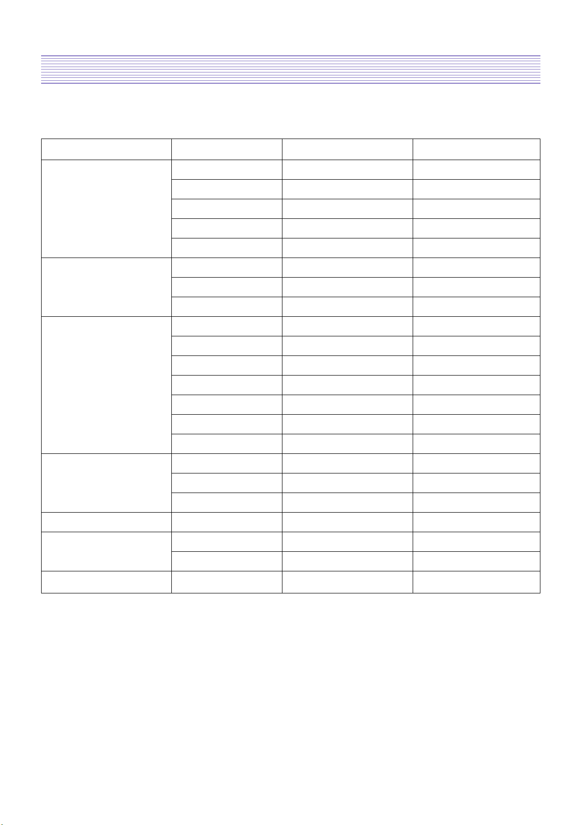
2. Product Specification
2-1. PRODUCT SPECIFICATION
Features DLX-26C2AMSB DLX-32C2AMSB
LCD Panel Screen Size 26” 32”
Aspect Ratio 16 : 9 16 : 9
Resolution 1366 X 768(WXGA) 1366 X 768(WXGA)
Pixel Pitch 0.4215mm 0.51075
Contrast Ratio 1000 : 1 800 : 1
TV System Receiving System PAL, SECAM PAL, SECAM
Stereo System 2-Carrer/NICAM 2-Carrer/NICAM
Channel Memory 99ch, Auto Preset 99ch, Auto Preset
Input Connector RF 75 Ohm Coaxial 75 Ohm Coaxial
S-Video 1 1
SCART 2 2
Component RCA X 1 RCA X 1
PC RGB D-Sub X 1 D-Sub X 1
PC Audio 3.5mm Mini-Jack 3.5mm Mini-Jack
HDMI 1 1
Output Connector SPDIF Optical-Jack Optical-Jack
Headphone 3.5mm Mini-Jack 3.5mm Mini-Jack
RF-out 1 1
Sound Output 10W 10W
Power Consumption Max. 120W 160W
Power Source 110-240V, 50-60Hz 110-240V, 50-60Hz
Dimension(W X H X D) Set Dimension 812 X 502.7 X 240 944 X 585.5 X 240
Product Specification
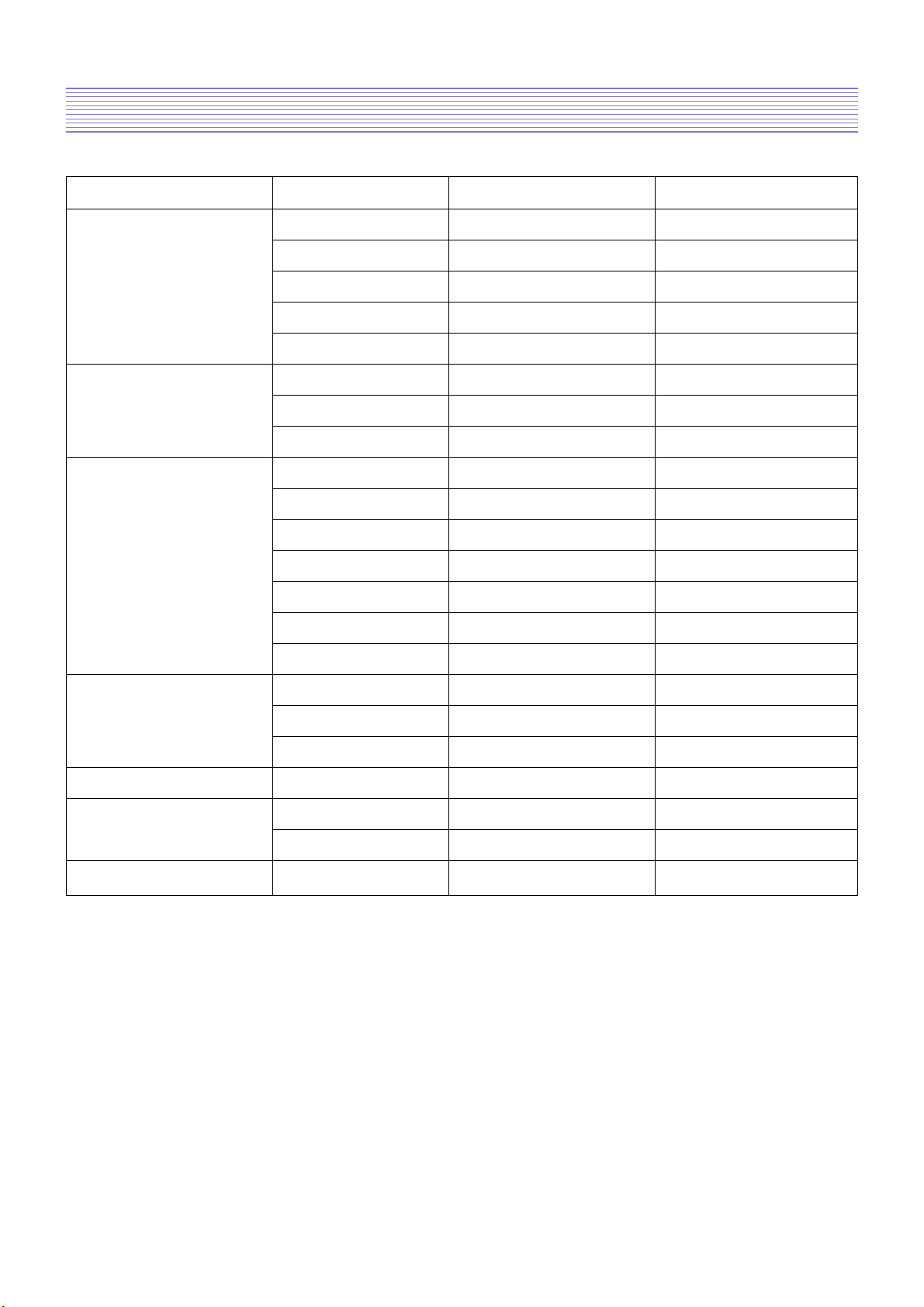
-5-
Features DLX-37C3LMBS DLX-42C1LMR
LCD Panel Screen Size 37” 42”
Aspect Ratio 16 : 9 16 : 9
Resolution 1366 X 768(WXGA) 1366 X 768(WXGA)
Pixel Pitch
0.2mm X 0.6mm X RGB
0.227mm X 0.681mm X RGB
Contrast Ratio 800 : 1 550 : 1
TV System Receiving System PAL, SECAM PAL, SECAM
Stereo System 2-Carrer/NICAM 2-Carrer/NICAM
Channel Memory 99ch, Auto Preset 99ch, Auto Preset
Input Connector RF 75 Ohm Coaxial 75 Ohm Coaxial
S-Video 1 1
SCART 2 2
Component RCA X 1 RCA X 1
PC RGB D-Sub X 1 D-Sub X 1
PC Audio 3.5mm Mini-Jack 3.5mm Mini-Jack
HDMI 1 1
Output Connector SPDIF Optical-Jack Optical-Jack
Headphone 3.5mm Mini-Jack 3.5mm Mini-Jack
RF-out 1 1
Sound Output 10W 10W
Power Consumption Max. 200W 220W
Power Source 110-240V, 50-60Hz 110-240V, 50-60Hz
Dimension(W X H X D) Set Dimension 940 X 655 X 129 1060 X 758 X 133
Product Specification
-6-
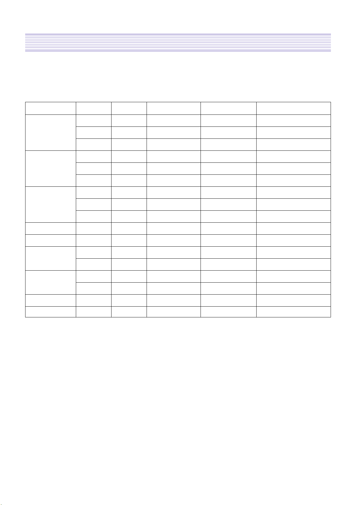
2-2. Available Input Signal
2-2-1. HDMI/ PC/COMPONENT
2-2-2. VIDEO
- PAL, PAL-M, PAL-N
- NTSC, NTSC4.43
- SECAM
Resolution V-freq HDMI PC(D-Sub) Component Standard
60Hz O O X
640 X 480 72Hz O O X
75Hz O O X VESA Standard
60Hz O O X VESA Standard
800 X 600 72Hz O O X VESA Standard
75Hz O O X
60Hz O O X VESA Standard
1024 X 768 70Hz O O X VESA Standard
75Hz O O X VESA Standard
720 X 480P 60Hz O X O
720 X 576P 50Hz O O O
1280 X 720P
50Hz O X O
60Hz O O O
1920 X 1080i
50Hz O X O
60Hz O O O
720 X 480i 60Hz X X O
720 X 576i 50Hz X X O
-7-
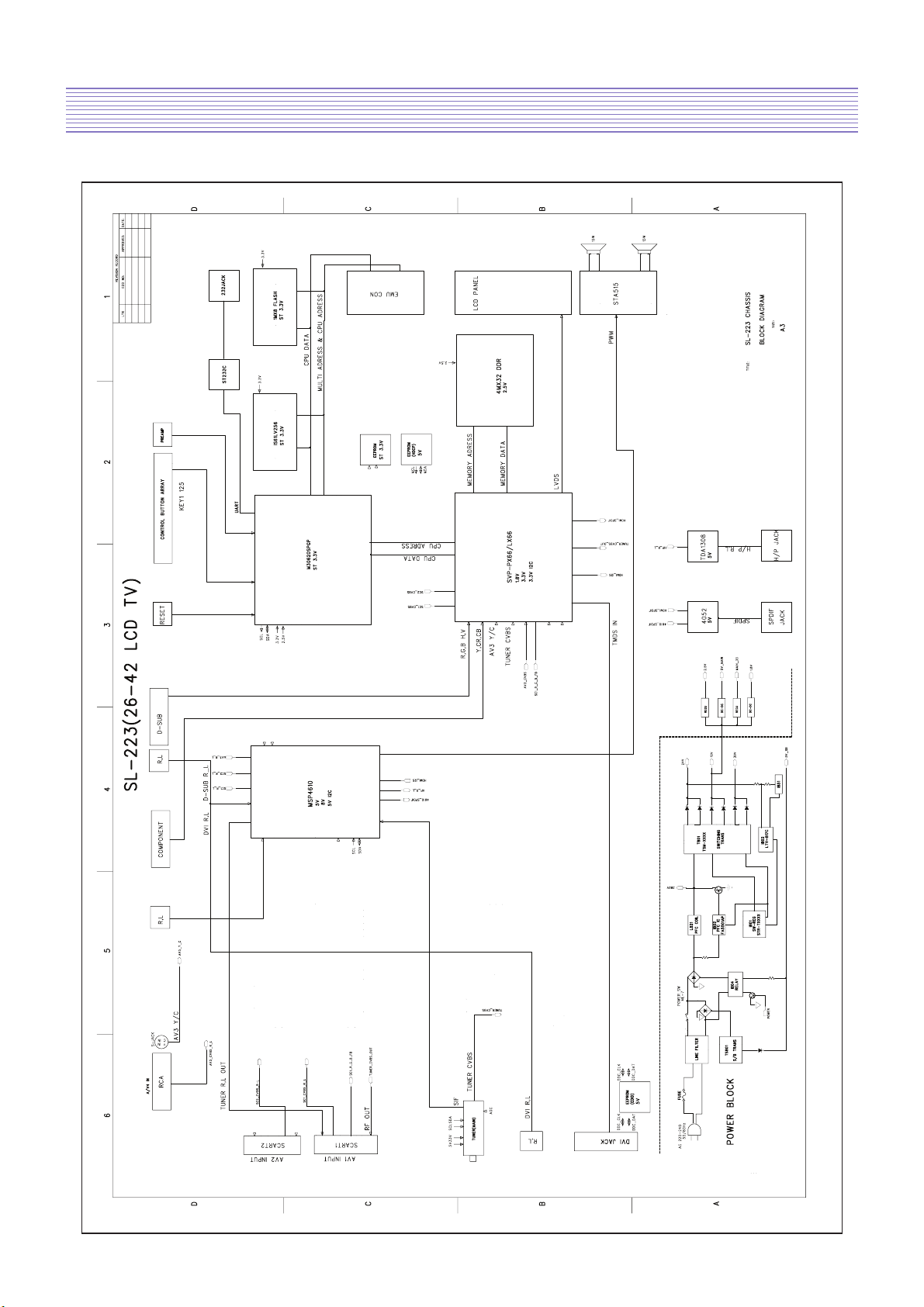
3. Block Diagram
-8-
4. Description of Each Block
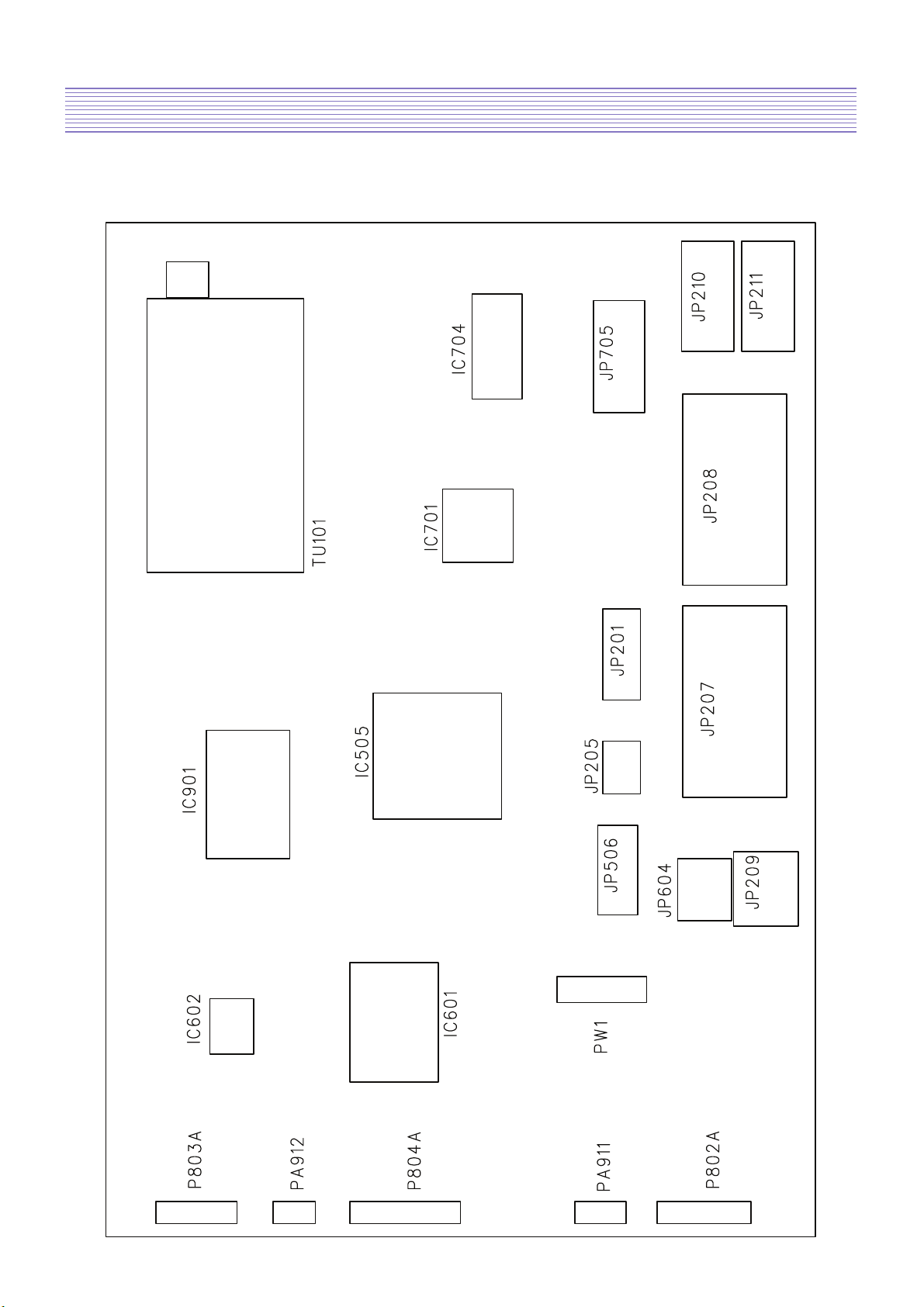
4-1. Block Diagram of Main IC and TP
-9-
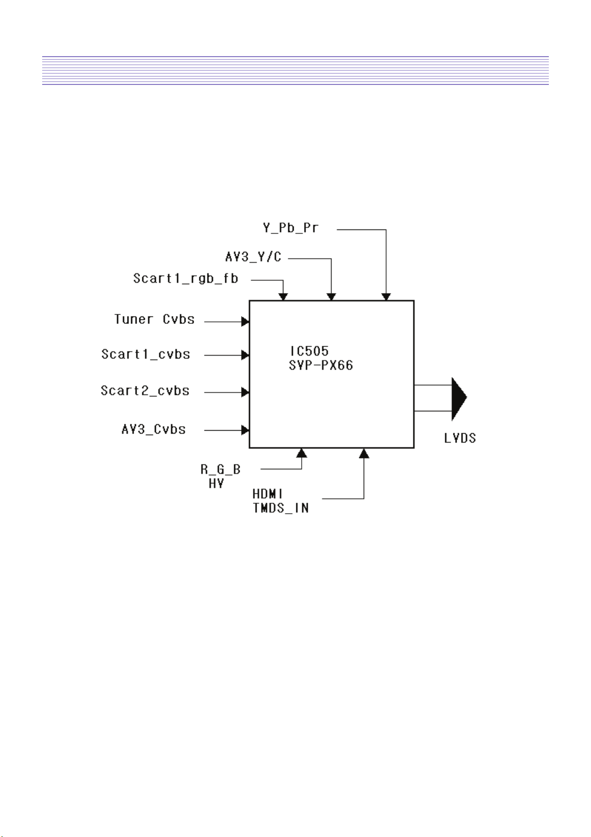
4-2. Overview
Digital PCB is Multi Media circuit board that can process various input signals such as
video, component, PC, HDMI, and analog TV signal.
4-2-1. Composite video, Y/C(S-Video) and SCART(CVBS, RGB) composite video
- Flow Chart of RF, Video, S-Video Signal
Description of Each Block
-10-
Description of Each Block
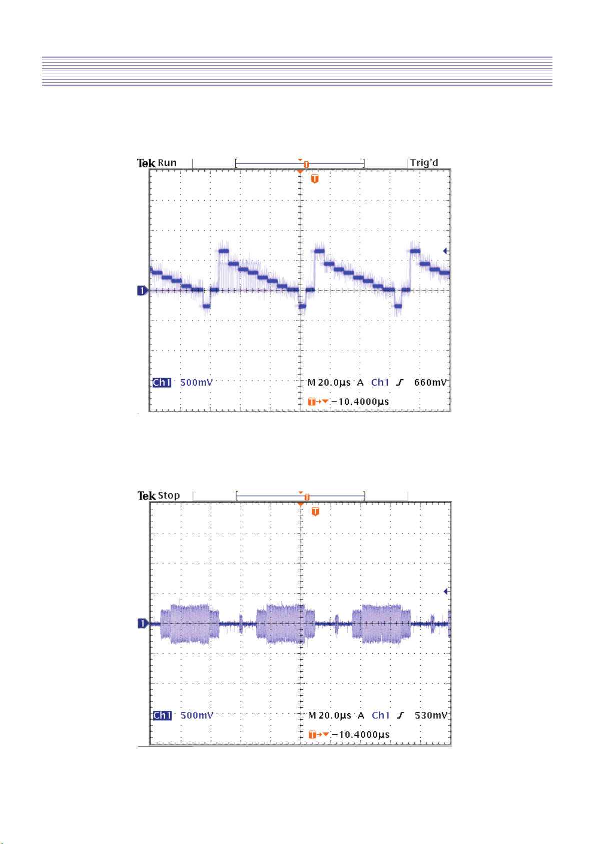
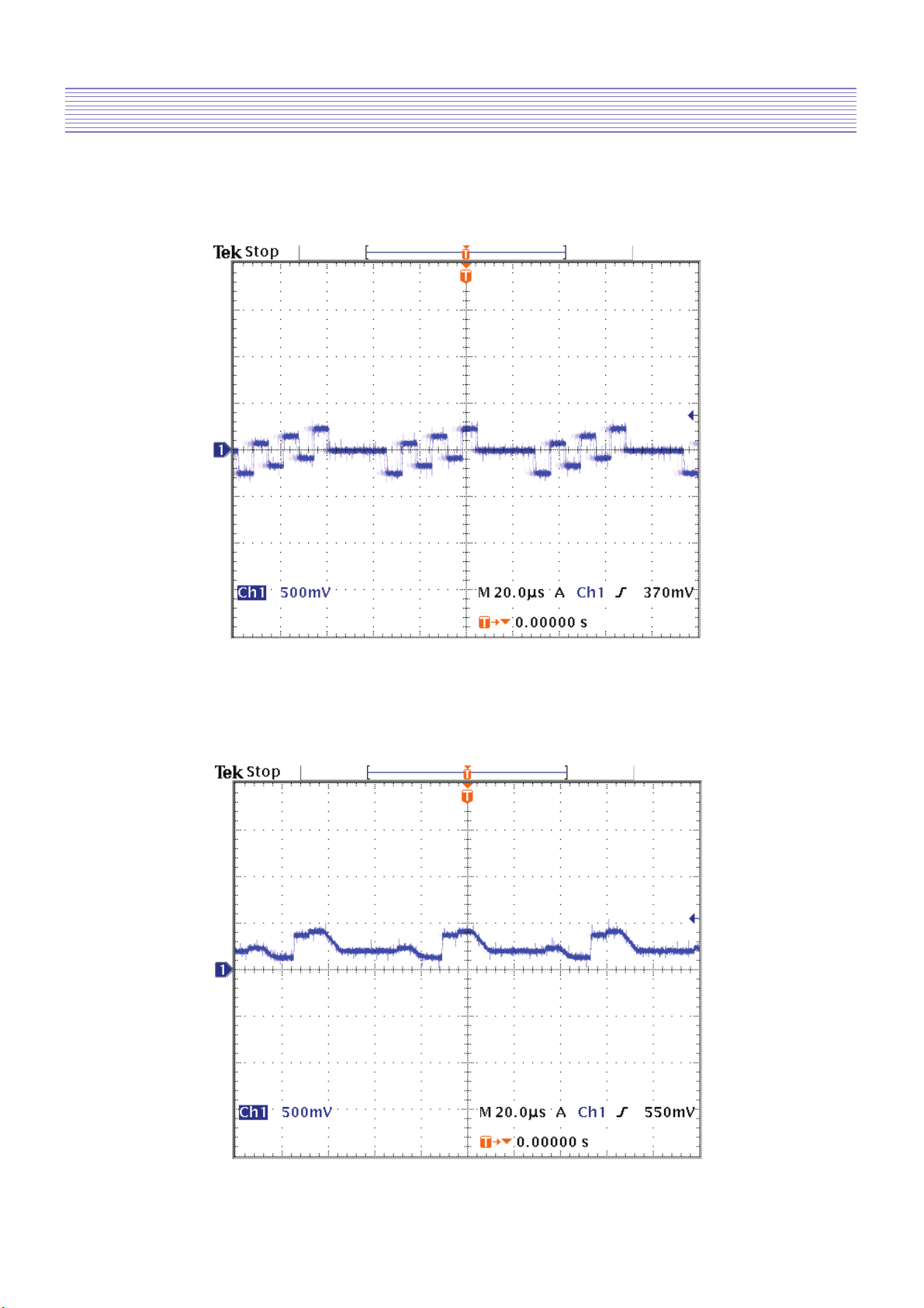
Y signal(input to IC505)
Location : CC451
Color signal(input to IC505)
Location : CC456
Description of Each Block
-11-
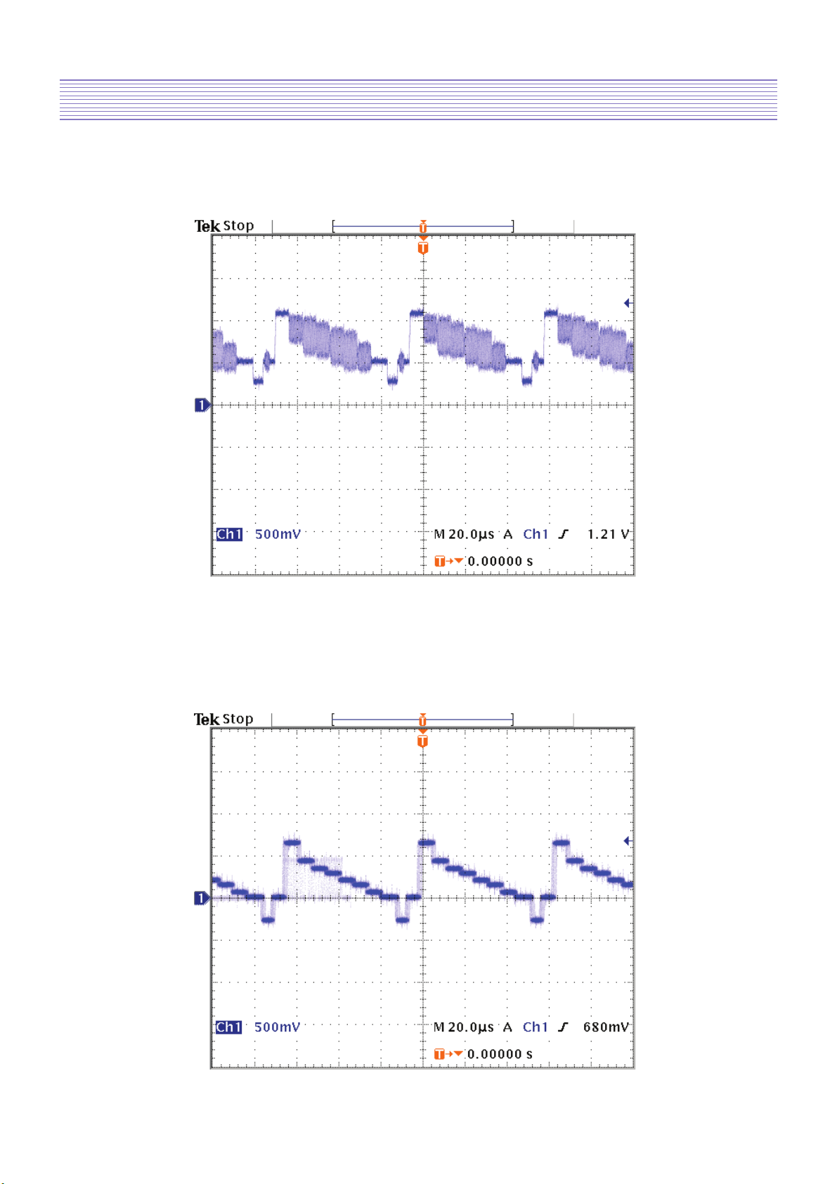
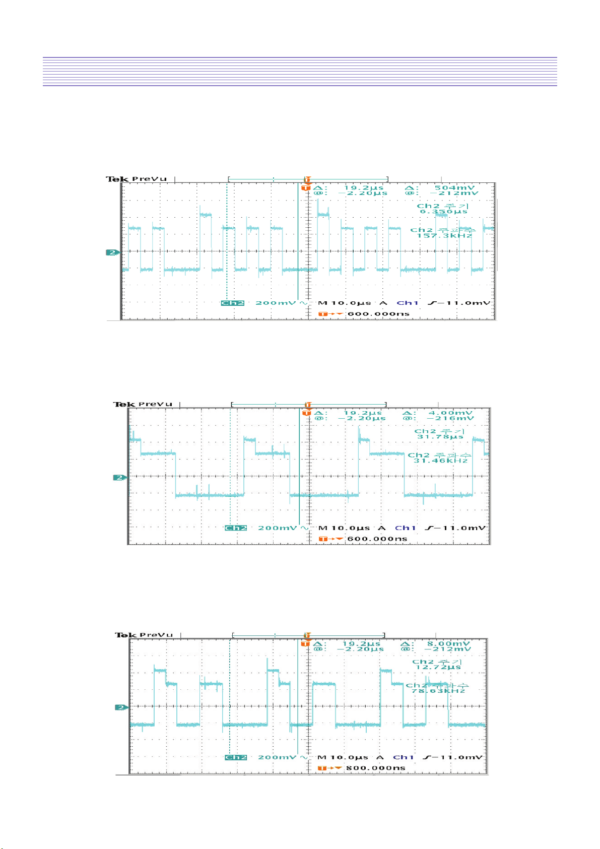
CVBS signal(input to IC505)
Location : CC455
4-2-2. DTV/DVD signal
Y signal(input to IC505)
Location : CC445
Description of Each Block
-12-
Pb signal(input to IC505)
Location : CC446
Pr signal(input to IC505)
Location : CC447
Description of Each Block
-13-
G signal(input to IC505)
Location : CC452
B signal(input to IC505)
Location : CC453
4-2-3. PC(Personal Computer) signal
R signal(input to IC505)
Location : CC454
Description of Each Block
-14-
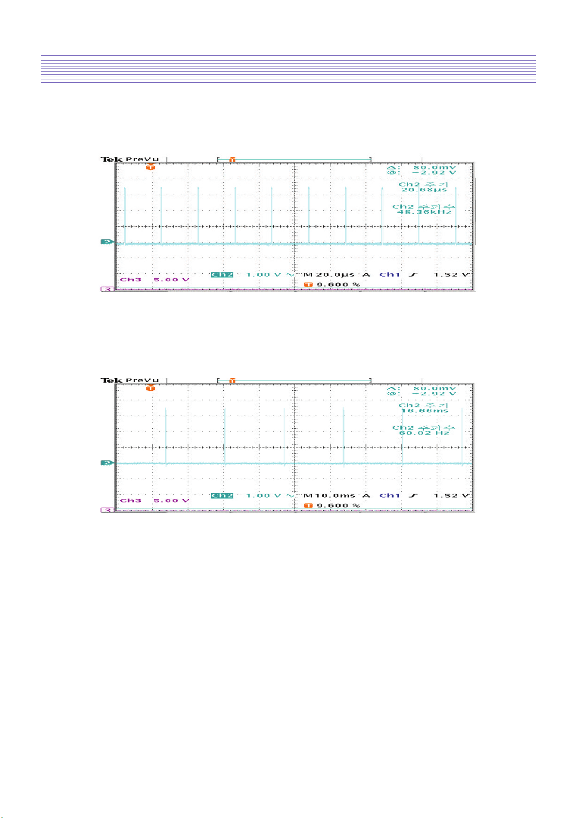
Horizontal sync(Output of IC505)
Location : RC458
Vertical sync(Output of IC505)
Location : RC459

Description of Each Block
-15-
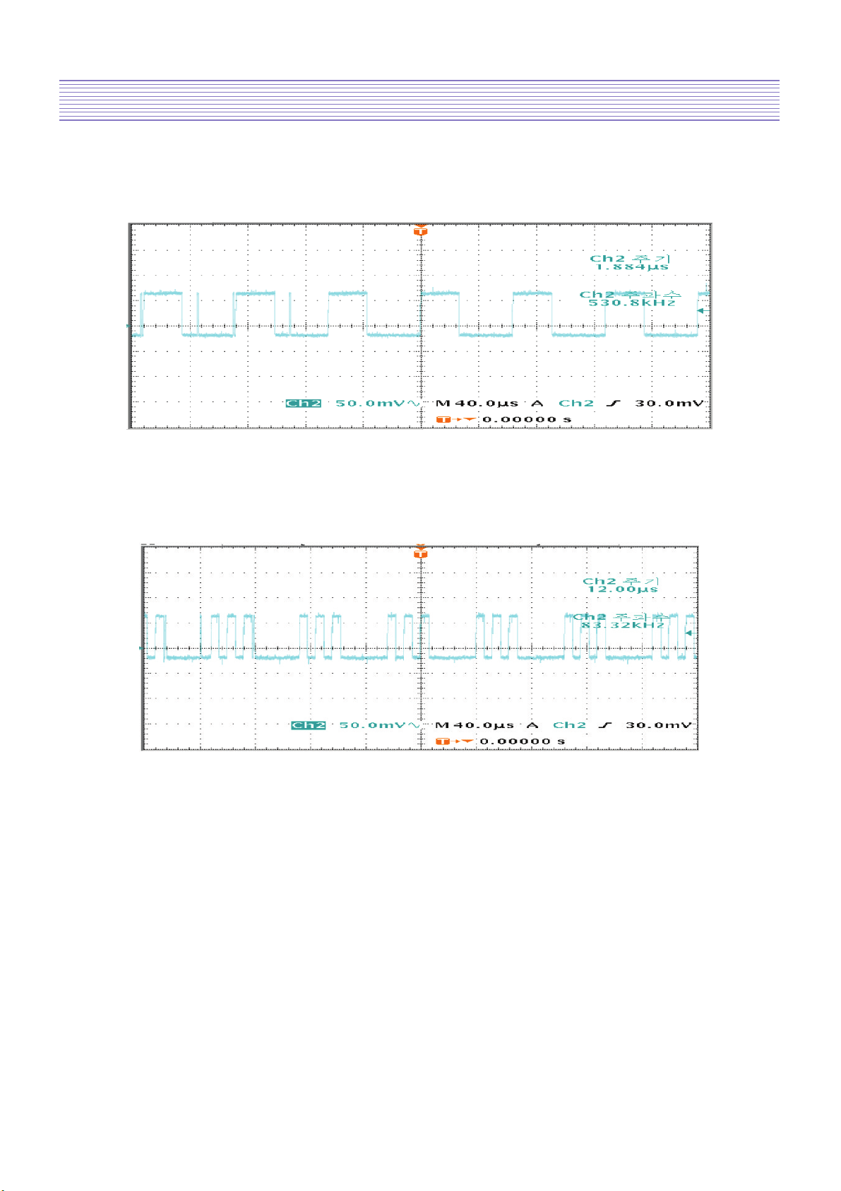
4-2-4. HDMI signal
Location : RC465, RC466, RC467, RC468, RC469, RC470, RC471, RC472
4-2-5. R/G/B PROCESSING(SCART1, TELETEXT R/G/B)
R signal (input to IC505)
Location : RC450
Description of Each Block
-16-
G signal(input to IC505)
Location : RC448
B signal(input to IC505)
Location : RC449
Description of Each Block
-17-
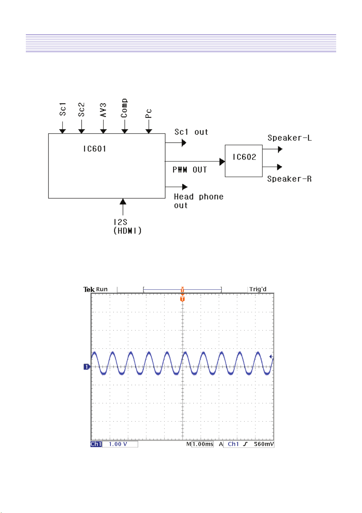
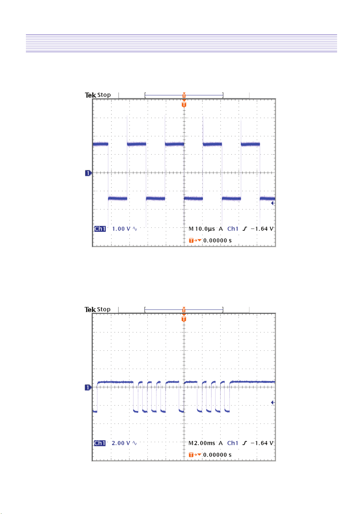
4-2-6. Audio signal processing, KEY, and LED
- Flow Chart of Audio signal
COMP-L sound
Location : ZA225
Description of Each Block
-18-
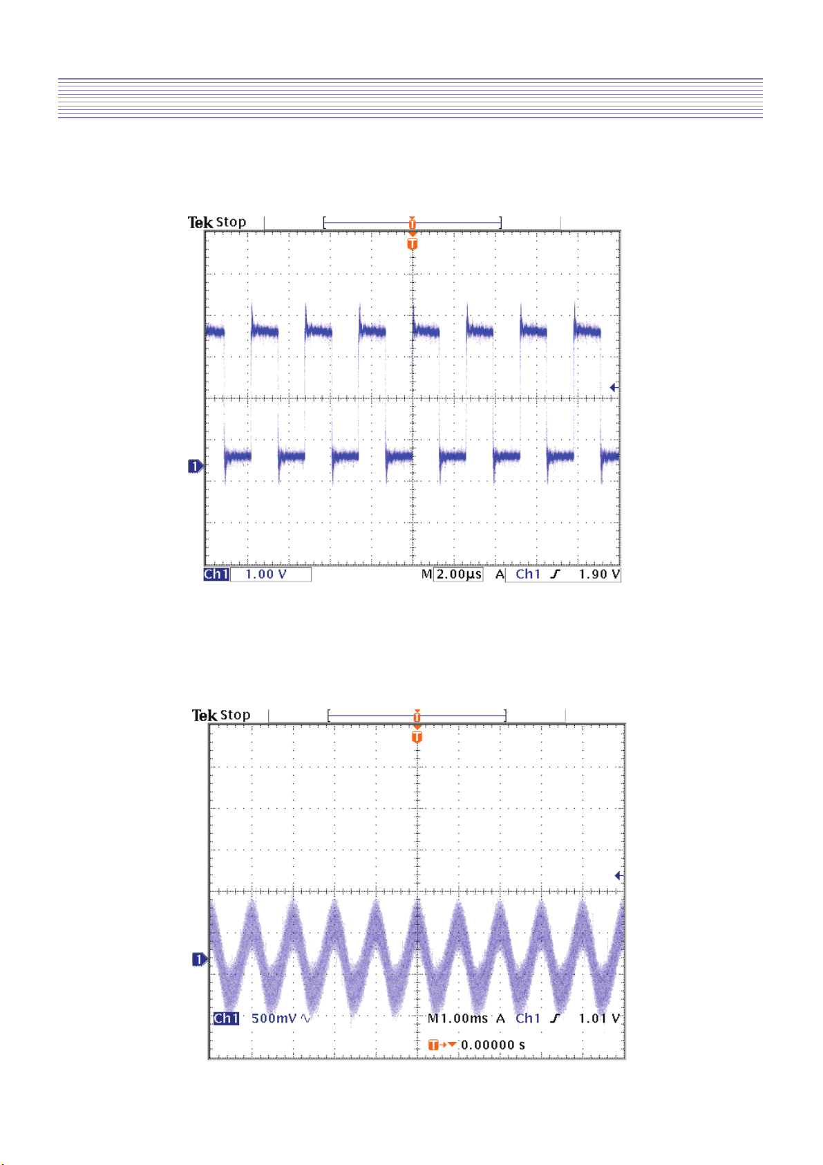
IC602 output
Location : L606, L610
IC602 input
Location : RC685, RC687
-19-
Description of Each Block
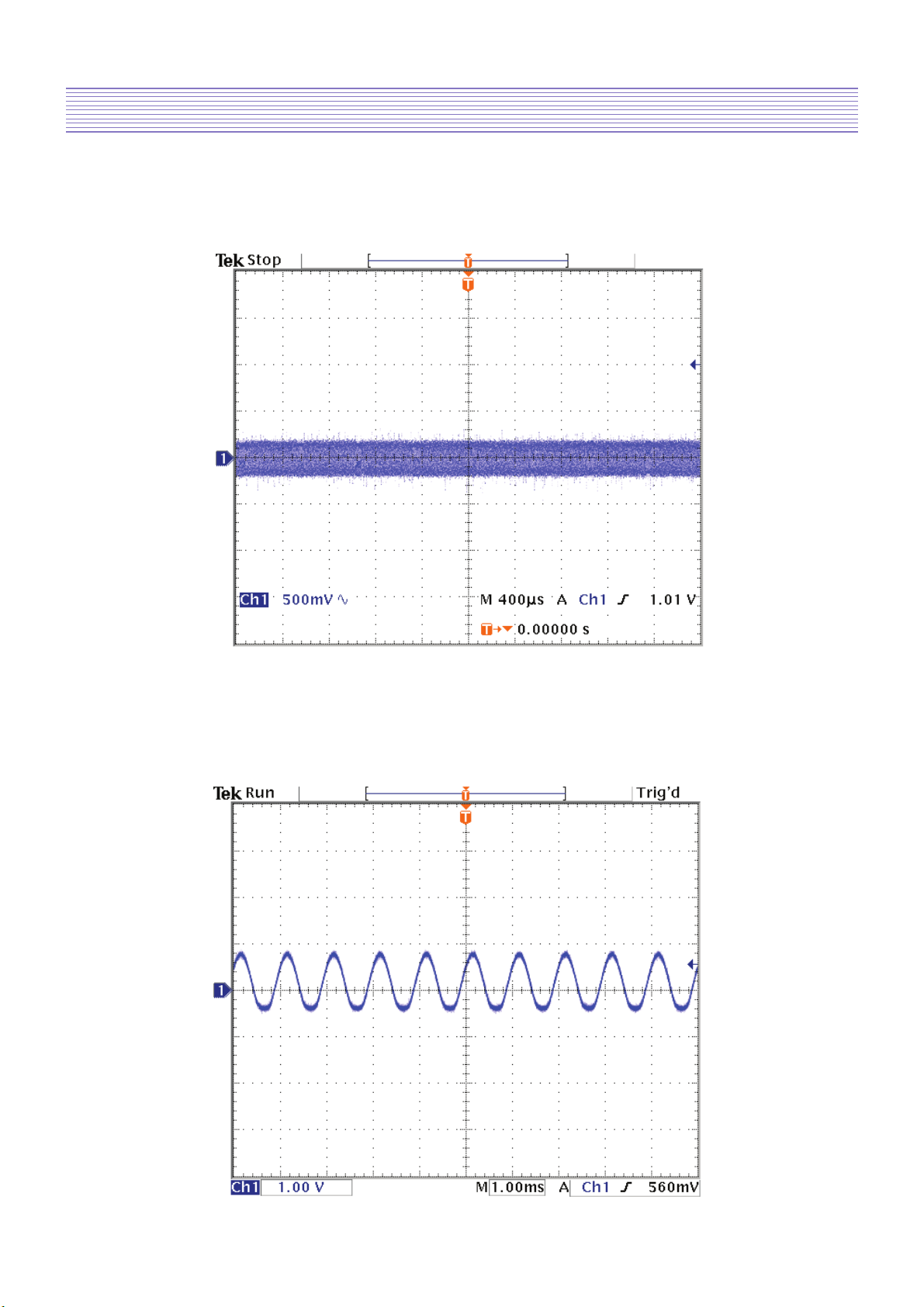
Headphone out
Location : RC611, RC612
SIF input
Location : CC654
-20-
Description of Each Block
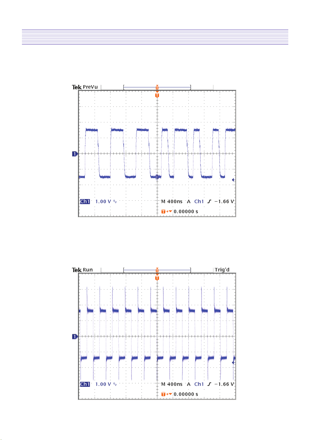
I2S input
Location : RC622(CLK)
SPDIF out
Location : RC655
-21-
Description of Each Block
Remote control signal
Location : RC722
Location : RC623(WS)
-22-
Description of Each Block
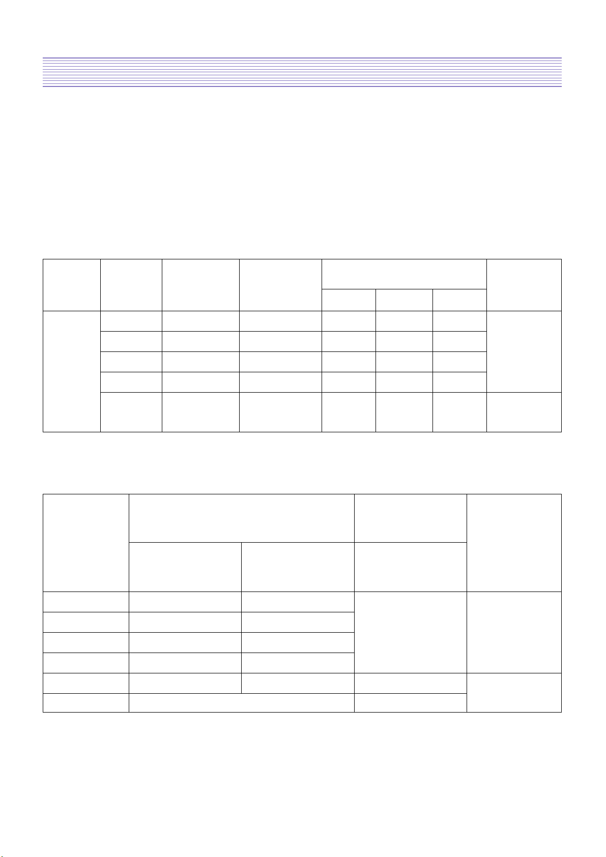
Output
Minimum Maximum
Output Current
Board
Voltage
output output Condition
voltage voltage MIN NOR MAX
+29Vdc +27.0Vdc +32.0Vdc 0.1A 0.5A 1A
+24Vdc +22.3Vdc +25.4Vdc 0.1A 6.0A 7.0A PWR-CTL
DEP +12Vdc +11.00Vdc +12.00Vdc 0.1A 1.5A 2.0A ON
+5Vdc +4.75Vdc +5.25Vdc 0.1A 1.5A 2.5A
ST +5Vdc
+4.75Vdc +5.25Vdc 0.1A 0.5A 0.6A
PWR-CTL
OFF
• Ripple and Noise
AC ripple,
Output Voltage switching ripple
Output and noise
Condition
Name Minimum Maximum
output output Continuous
voltage voltage
+29V +27.0Vdc +32.0Vdc
PWR-CTL
+24V +22.3Vdc +25.4Vdc
500mVp-p
ON
+12V +11.00Vdc +12.00Vdc
+5V +4.75Vdc +5.25Vdc MAX LOAD
ST +5V +4.75Vdc +5.25Vdc 500mVp-p PWR-CTL
Other Lines Don’t Care OFF
4-3. POWER PCB
4-3-1. POWER SPEC
• Rating : 110V~240V
• Regulating Method :
• Input Frequency : 50/60Hz
• Inrush Current : Below 80A at AC230V
• Output Voltage and Current are shown below.
-23-
Description of Each Block
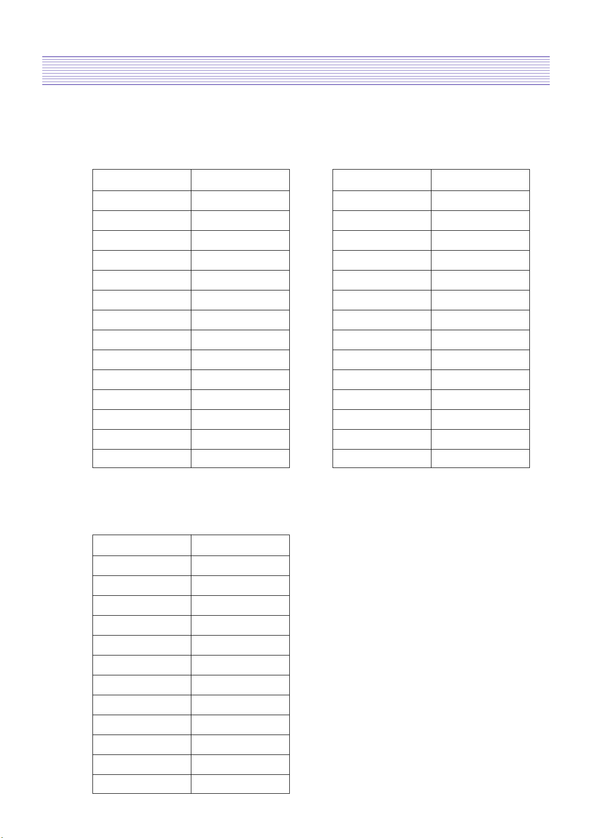
4-3-2. Connectors
A. CN7, CN8 pin Spec(YEN-HO 20010WS-14 14P)
B. CN5, CN6 Pin Spec(YEON-HO 20010WS -12 12P)
CN7(AUO PANNEL)
PIN NO. OUTPUT
1 +24V
2 +24V
3 +24V
4 +24V
5 +24V
6 GND
7 GND
8 GND
9 GND
10 GND
11 DIMIMING
12 INV ON/OFF
13 N/C
14 GND
CN5, CN6(LG PANNEL)
PIN NO. OUTPUT
1 +24V
2 +24V
3 +24V
4 +24V
5 +24V
6 GND
7 GND
8 GND
9 GND
10 GND
11 DIMIMING
12 INV ON/OFF
CN8(SAMSUNG PANNEL)
PIN NO. OUTPUT
1 +24V
2 +24V
3 +24V
4 +24V
5 +24V
6 GND
7 GND
8 GND
9 GND
10 GND
11 N/C
12 INV ON/OFF
13 DIMIMING
14 N/C
 Loading...