

Page 1

S/M NO. : DSL150TP00
Service Manual
19”,20”,22” LCD TV
CHASSIS: SL-150T/150P
Model: DLT-19W4 / DLP-19W4
DLT-22W4 / DLP-22W4
DLT-20J1 / DLP-20J1M
DLT-20J3 / DLP-20J3M
DLT-20J9 / DLP-20J9M
DLT-19L1 / DLP-19L1
DLT-19L2 / DLP-19L2
DLT-22L1 / DLP-22L1
DLT-22L2 / DLP-22L2
Caution:
In this manual some parts can be changed for improving. Their
performance without notice in the parts list. So, if you need the latest parts information, please refer to PPL(Parts Price List) in Service
Information Center.
JAN. 2008
Page 2

Contents
I. Parts with the exception of MODULE
1. Safety Precaution . . . . . . . . . . . . . . . . . . . . . . . . . . . . . . . . . . . . . . . . . . . . . . . . . . . . . . . . .2
2. Product Specification . . . . . . . . . . . . . . . . . . . . . . . . . . . . . . . . . . . . . . . . . . . . . . . . . . . . . .3
3. Block Diagram . . . . . . . . . . . . . . . . . . . . . . . . . . . . . . . . . . . . . . . . . . . . . . . . . . . . . . . . . . . . .4
4. Schematic Diagram . . . . . . . . . . . . . . . . . . . . . . . . . . . . . . . . . . . . . . . . . . . . . . . . . . . . . . . .6
5. PCB Data . . . . . . . . . . . . . . . . . . . . . . . . . . . . . . . . . . . . . . . . . . . . . . . . . . . . . . . . . . . . . . . . . .14
6. Trouble Shooting . . . . . . . . . . . . . . . . . . . . . . . . . . . . . . . . . . . . . . . . . . . . . . . . . . . . . . . . . .22
7. Service Part List . . . . . . . . . . . . . . . . . . . . . . . . . . . . . . . . . . . . . . . . . . . . . . . . . . . . . . . . . . . .30
8. Different part list for models . . . . . . . . . . . . . . . . . . . . . . . . . . . . . . . . . . . . . . . . . . . . . . .38
9. Electrical Requirements . . . . . . . . . . . . . . . . . . . . . . . . . . . . . . . . . . . . . . . . . . . . . . . . . . . .48
10. Out Line . . . . . . . . . . . . . . . . . . . . . . . . . . . . . . . . . . . . . . . . . . . . . . . . . . . . . . . . . . . . . . . . . .54
11. Exploded View . . . . . . . . . . . . . . . . . . . . . . . . . . . . . . . . . . . . . . . . . . . . . . . . . . . . . . . . . . .58
12. Software Install & Upgrade . . . . . . . . . . . . . . . . . . . . . . . . . . . . . . . . . . . . . . . . . . . . . . . .62
13. SVC keys function . . . . . . . . . . . . . . . . . . . . . . . . . . . . . . . . . . . . . . . . . . . . . . . . . . . . . . . .73
* Remarks
Points from 3 show data for DLT models.
For DLP models diffrent part list for models (point 8) must be used.
1
Page 3

1. Safety Precautions
(1) When moving or laying down a LCD Set, at least two people must work together. Avoid any
impact towards the LCD Set.
(2) Do not leave a broken LCD Set on for a long time. To prevent any further damages, after
checking the condition of the broken Set, make sure to turn the power (AC) off.
(3) When opening the BACK COVER, you must turn off power (AC) to prevent any electric
shock.
(4) When loosening screws, check the position and type of the screw. Sort out the screws and
store them separately for reassembling. Because screws holding PCBs are working as electric circuit grounding, make sure to check if any screw is missing when assembling / reassembling. Do not leave any screws inside the set.
(5) A LCD Set contains different kinds of connector cables. When connecting or disconnecting
cables, check the direction and position of the cable beforehand.
(6) Connect/disconnect the connectors slowly with care especially FFC (film) cables and FPC
cables. Do not connect or disconnect connectors instantaneously with force, and handle
them carefully for reassembling.
(7) Connectors are designed so that if the number of pins or the direction does not match,
connectors will not fit. When having problem in plugging the connectors, check their kind,
position, and direction.
2
Page 4
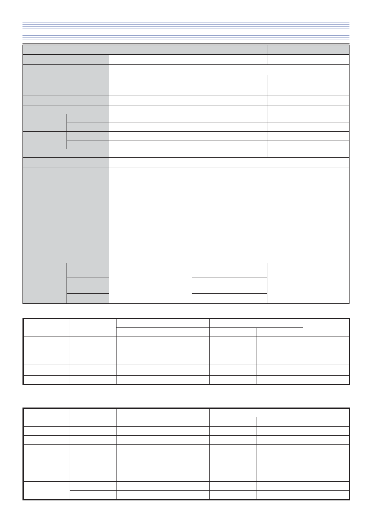
2. Product Specifications
Model DLT-19W4 / DLP-19W4 DLT-20Jx / DLP-20JxM DLT-22W4 / DLP-22W4
Screen Size 480mm (diagonal) 510.54mm (diagonal) 558.673mm (diagonal)
Display Colour 16.7 M
Aspect Ratio 16:10 4:3 16:10
Resolution 1440 x 900 (WXGA+) 640 x 480 (VGA) 1680 x 1050 (WSXGA+)
Pixel Pitch 0.2835 x 0.2835 0.6375 x 0.6375 0.2835 x 0.2835
Contrast Ratio 1000:1 350:1 1000:1
Appearance
(W x H x D)
Weight
(Net)
Power Consumption 42W / 39W 52W / 49W 50W / 46W
Sound Output 2.0W + 2.0W
Terminals
Reception Channel
Power Source AC 220 ~ 240V, 50Hz
The following picture
formats is
available:
w/o stand
with stand
w/o stand
with stand
RF, AV1, AV2
MODE
COMPONENT,
HDMI, PC
DVB-T MODE
476.3 x 346 x 80 514 x 460 x 85 545.4 x 400 x 81
476.3 x 401.5 x 190 514 x 498 x 239 545.4 x 426 x 190
4.9 Kg 7.0 Kg 5.6 Kg
5.2 Kg 8.0 Kg 5.9 Kg
AV IN : SCART, COMPOSITE VIDEO, AUDIO L/R,
COMPONENT, PC, HDMI
HEADPHONE : 3.5mm STEREO MINI-JACK
DIGITAL AUDIO OUT: Coaxial
ANT. IN : COAXIAL-TYPE
VHF BAND I : CH2-CH4
BAND II : CH5-CH12
UHF HYPER BAND : SI’-S3’, S1-S20
BAND IV, V : CH21-CH68
PAL-B/G, D/K, SECAM-L/L’, NTSC(AV input only)
WIDE, FULL SCREEN
4:3, FULL SCREEN
FULL SCREEN
WIDE, FULL SCREEN
4:3, FULL SCREEN
PC Input resolution in LCD
Resolution V-Freq
640 x 480 60Hz o o o o
800 x 600 60Hz o o x x
1024x768 60Hz o o x x
1280x768 60Hz o x x x
1440 x 900 60Hz o x x x
DLT/P-19W4, 22W4 DLT/P-20J1, 20J3, 20J9
PC(D-Sub) HDMI PC(D-Sub) HDMI
Multimedia input resolution table in LCD
Resolution V-freq
720 x 480i 60Hz oxox
720 x 480p 60Hz o o o o
720 x 576i 60Hz oxox
720 x 576p 60Hz o o o o
1280 x 720p
1920 x 1080i
50Hz o o o o
60Hz o o o o
50Hz o o o o
60Hz o o o o
DLT/P-19W4, 22W4 DLT/P-20J1, 20J3, 20J9
Component HDMI Component HDMI
Remark
Remark
3
Page 5
p\WX
o|kzvuGpp
mspZW]WYo
oktpGX
oktpGY
Ovw{pvuP
oktp
z~
OP
{|uly
{k{nTzXW[kG
zpm
ymj}iz
wjG
kTz
yVnViVoV}
yVs
yVs
zjhy{
yVnVi
j}iz
yVs
j}iz
j
yVs
VwVw
yjhGq
j}iz
yVs
h
htw
y
s
oVw
s}kzGOX`”~SYY”~
P
sjk
whuls
p\W\
z
mshzo
p\W[
llwyvt
hGpYj
pjkXZ
jvmkt
z{}WZ]Y
pkWY
z{\XW\
jp
{z
kh{h
kGpYj
pkWZ
zkyht
pkX_
m
j
zwkpm
yVnViVj}iz
zwkpm
pkWY
llwyvt
kGpYj
zpmGpu
ymGj}izGpu
oktpGpu
jvtwvulu{
pu
wjGpu
yni
j}izGpu
j}izGv|{
h|kpvGpu
h|kpvGv|{
zjhy{Gpu
jvtwGhGpu
h}YGj}izGpu
h}GhGpu
zwkpmGv|{
{{sOYWUX”P
wjGh
pkXW
pYjGz~
hGGpYj
kGpYj
pkX[
X]Y[[
pkW^
X]Y[[
pkX^
ojXY]
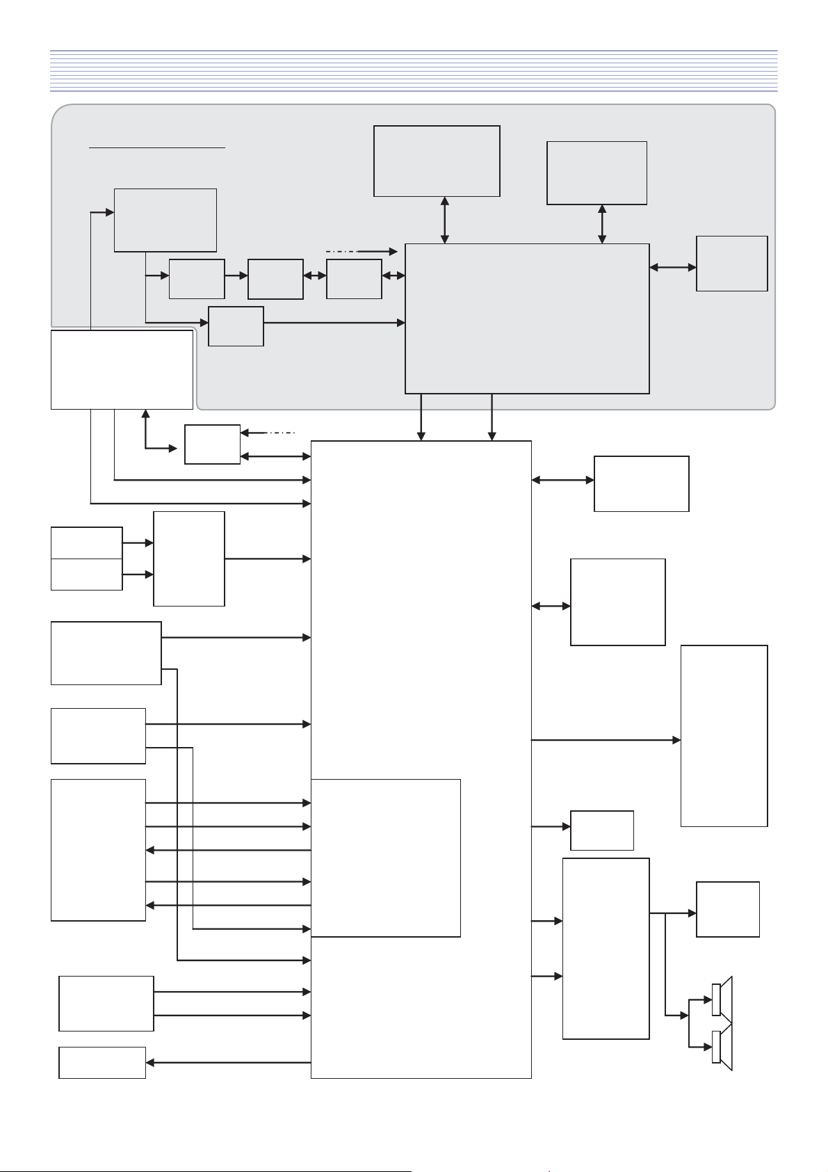
3. Block Diagram (Main)
* DLT model only
4
Page 6
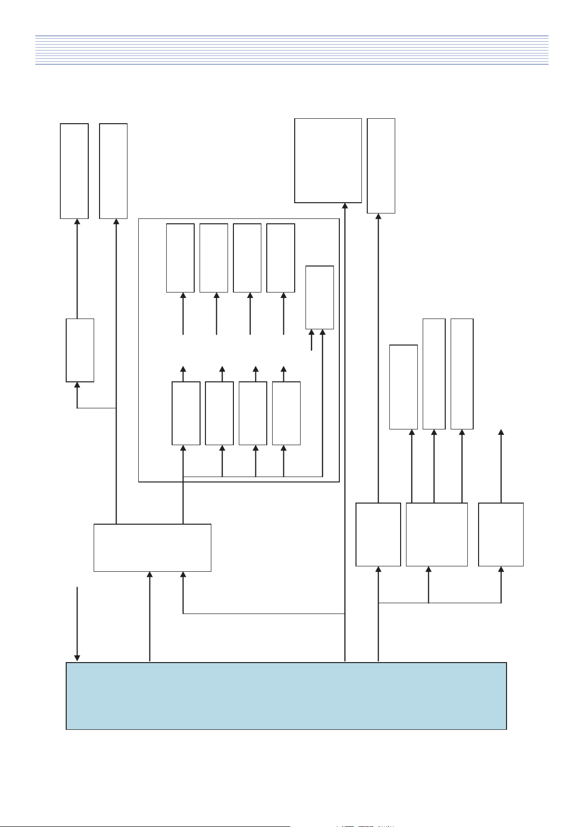
Block Diagram (Power Lips)
{|uly
h|kpvGhtw
pkWYOz{\XW\P
\}{|
pkWZOzkyhtP
YU\}
pkX_OmshzoP
pkX\OllwyvtP
ZUZ}
pkXZOjvmktP
wkWZ
w\W_G
pkXWGOGpYjGz~GP
pjXYGOpjGwylhtwP
whulsOzVzSh|vP
qkWY
wjtjph
p`YX
ylnU\}
ZUZ}SYU\}SXUY}
ZUZ}SYU\}SXUW}
ZUZ}
k}iT{
p\W\GOzGmshzoP
ZUZ}
kjTkjGjU
p\W[GOllwyvtP
p`XZ
XU_}
kjTkjGjU
X[U\}OX\}Pz~
ml{
p`X\
p`WY
ylnUZUZ}
\}z~
p`XX
ylnUYU\}
p`X[
p`X]
ylnUXUY}
ylnUXUW}
\}jp
p`W^
mspZW]WYoP
p\WXOo|kzvuGpp
\}
kjTkjGjU
p`XY
isluSishkq
X[U\}OX\}P
\}
_U\}
spwz
wv~ly
5
Page 7
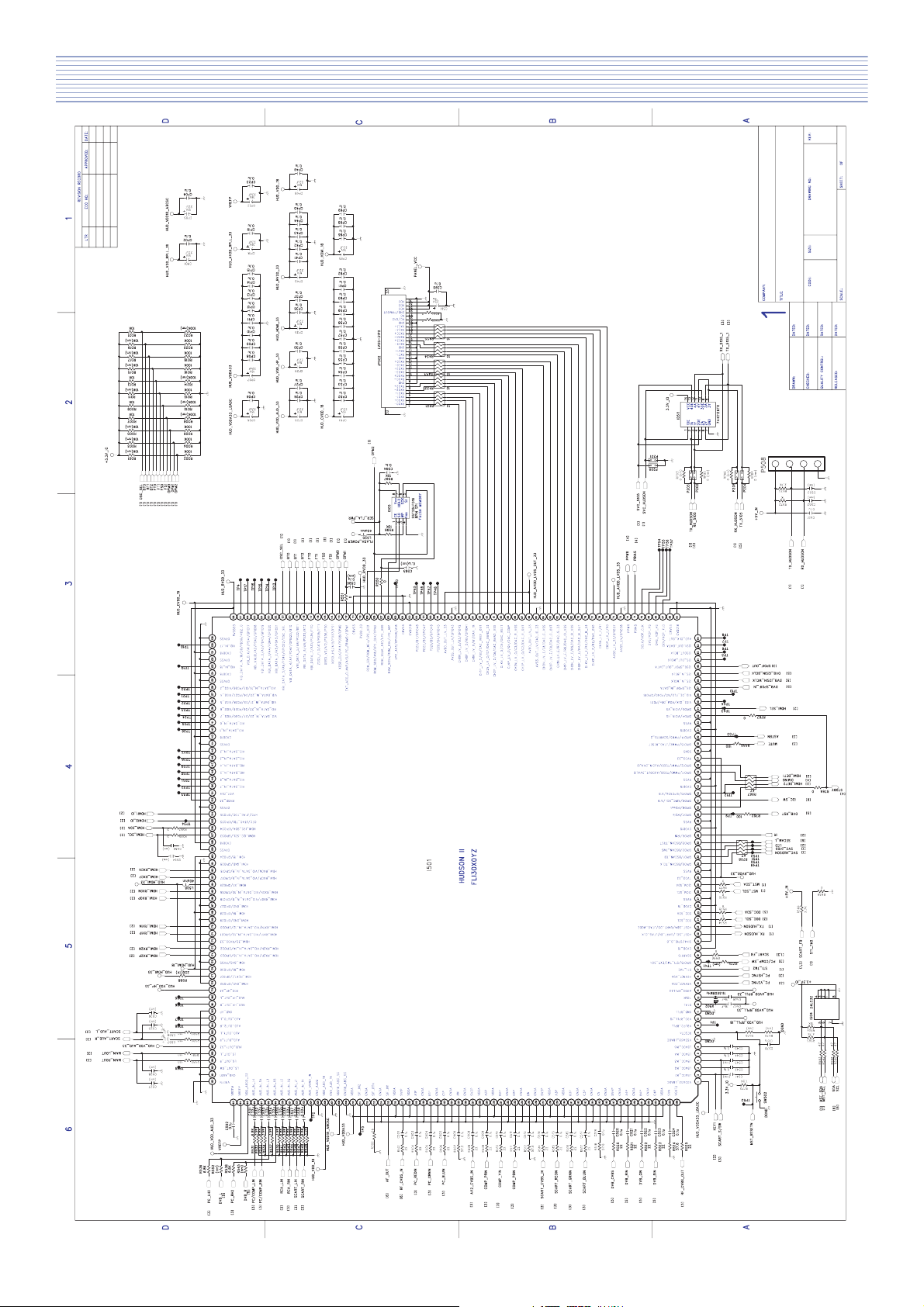
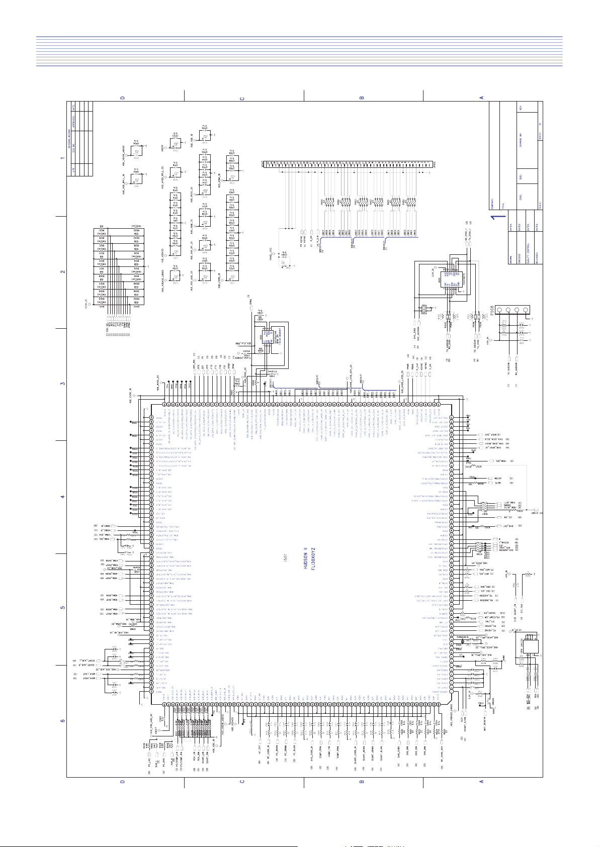
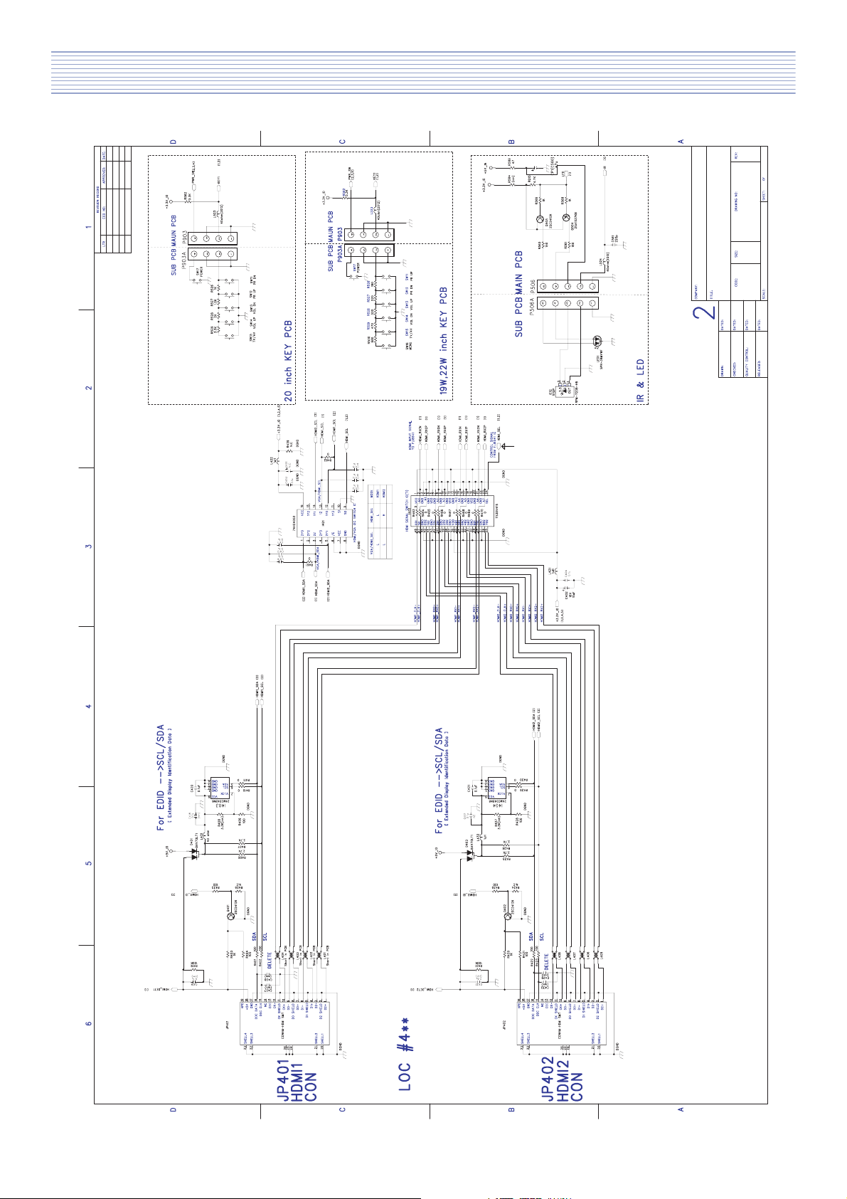
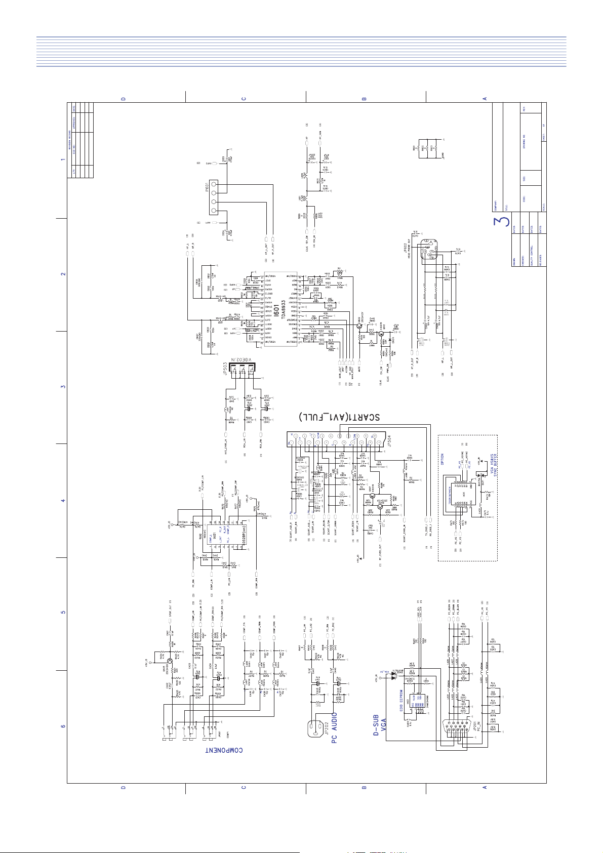
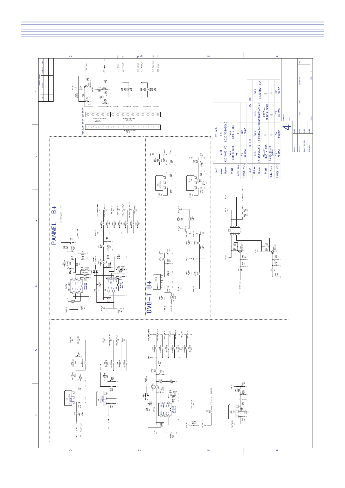
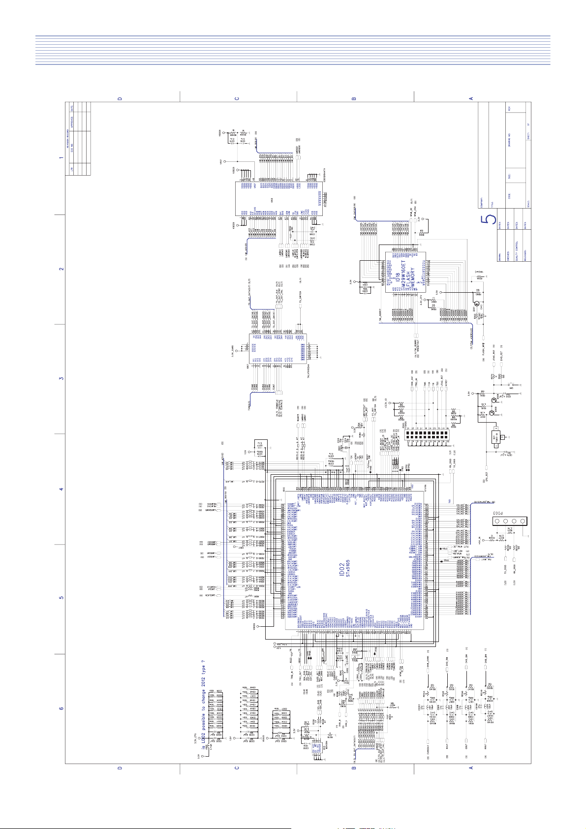
4. Schematic Diagram (DLT-19W4, DLT-22W4)
6
Page 8
Schematic Diagram (DLT-20J1, DLT-20J3)
7
Page 9
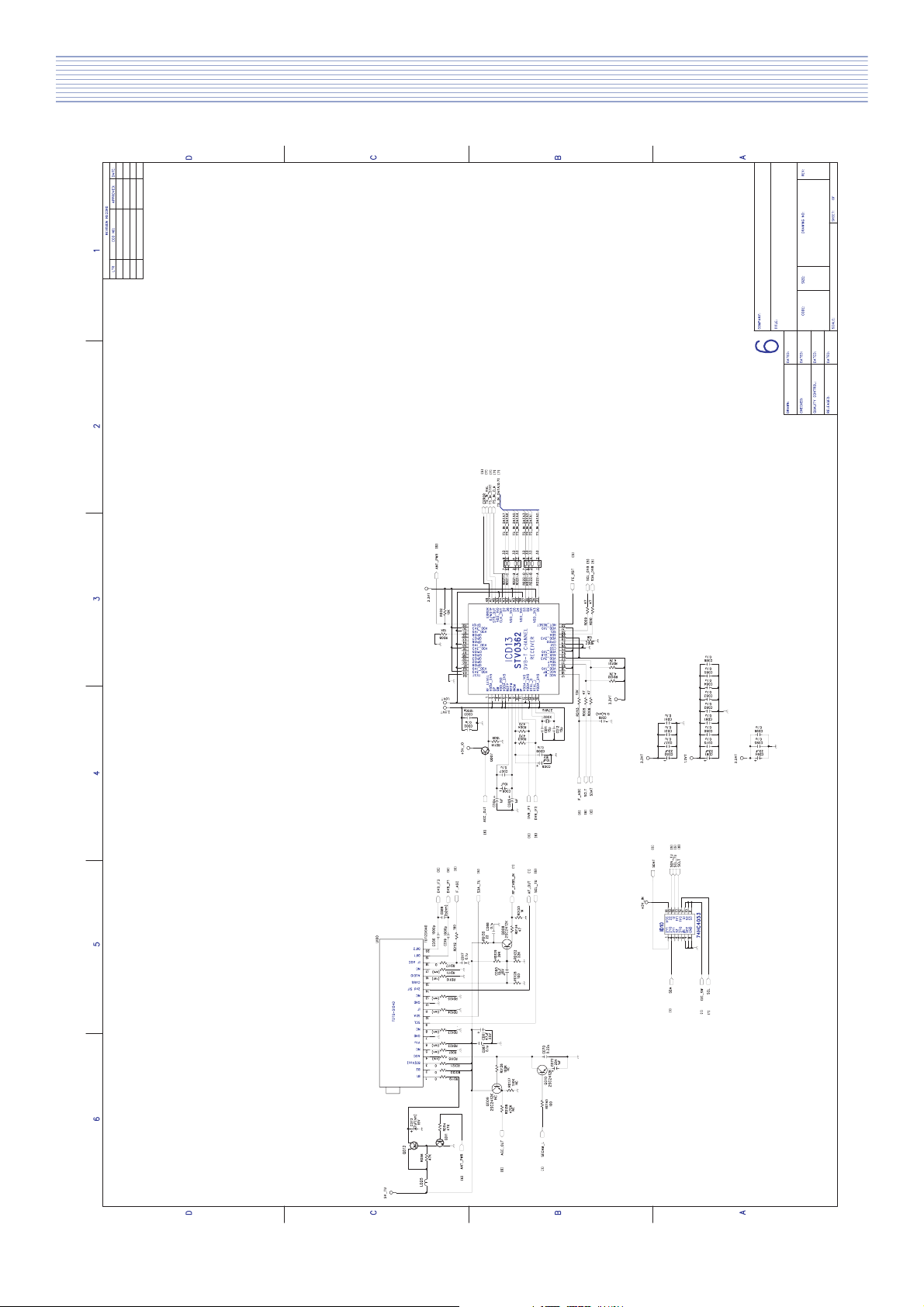
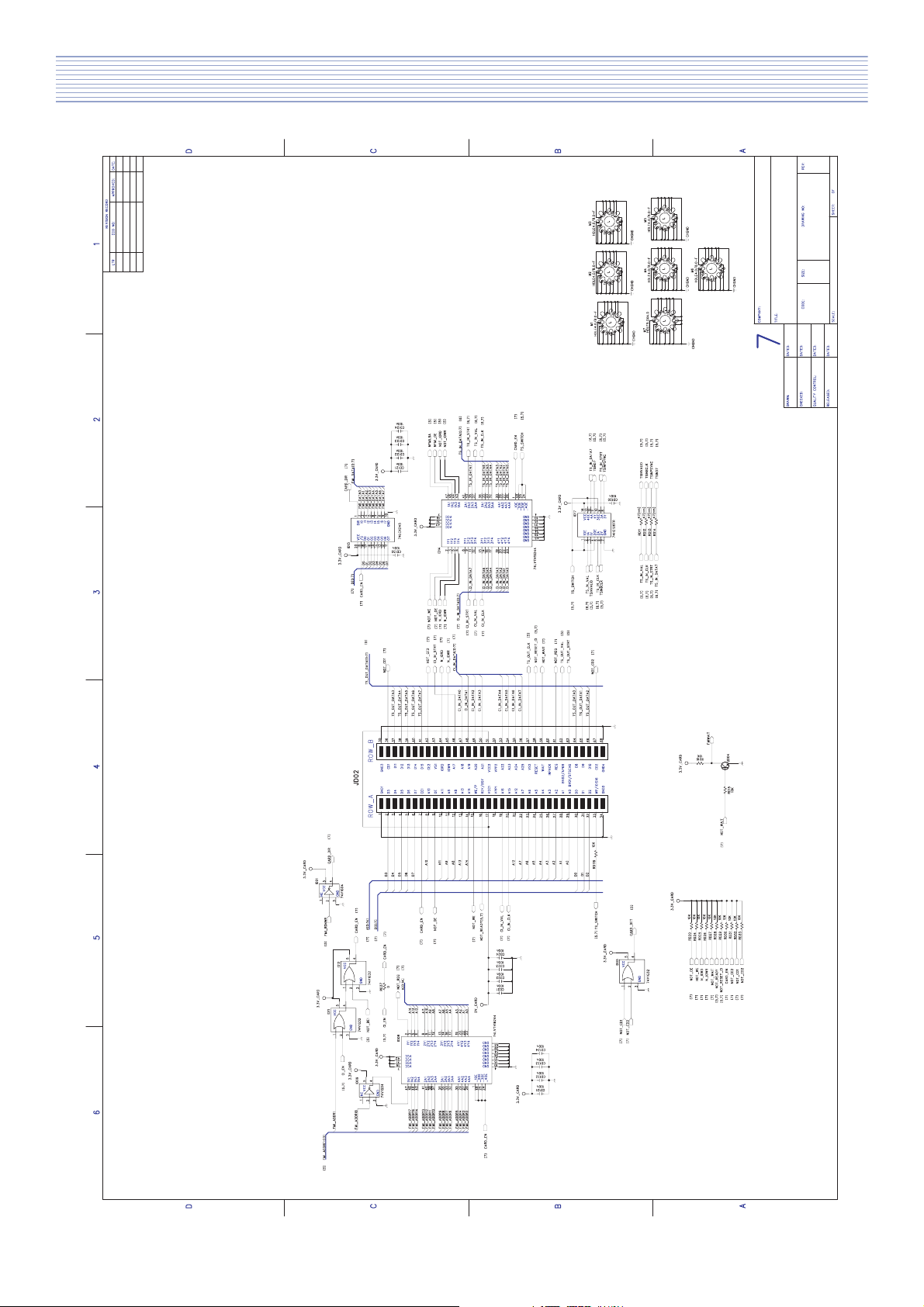
Schematic Diagram
8
Page 10
Schematic Diagram
9
Page 11
Schematic Diagram
10
Page 12
Schematic Diagram
This page can be used only for DLT models
11
Page 13
Schematic Diagram
12
Page 14
Schematic Diagram
13
Page 15
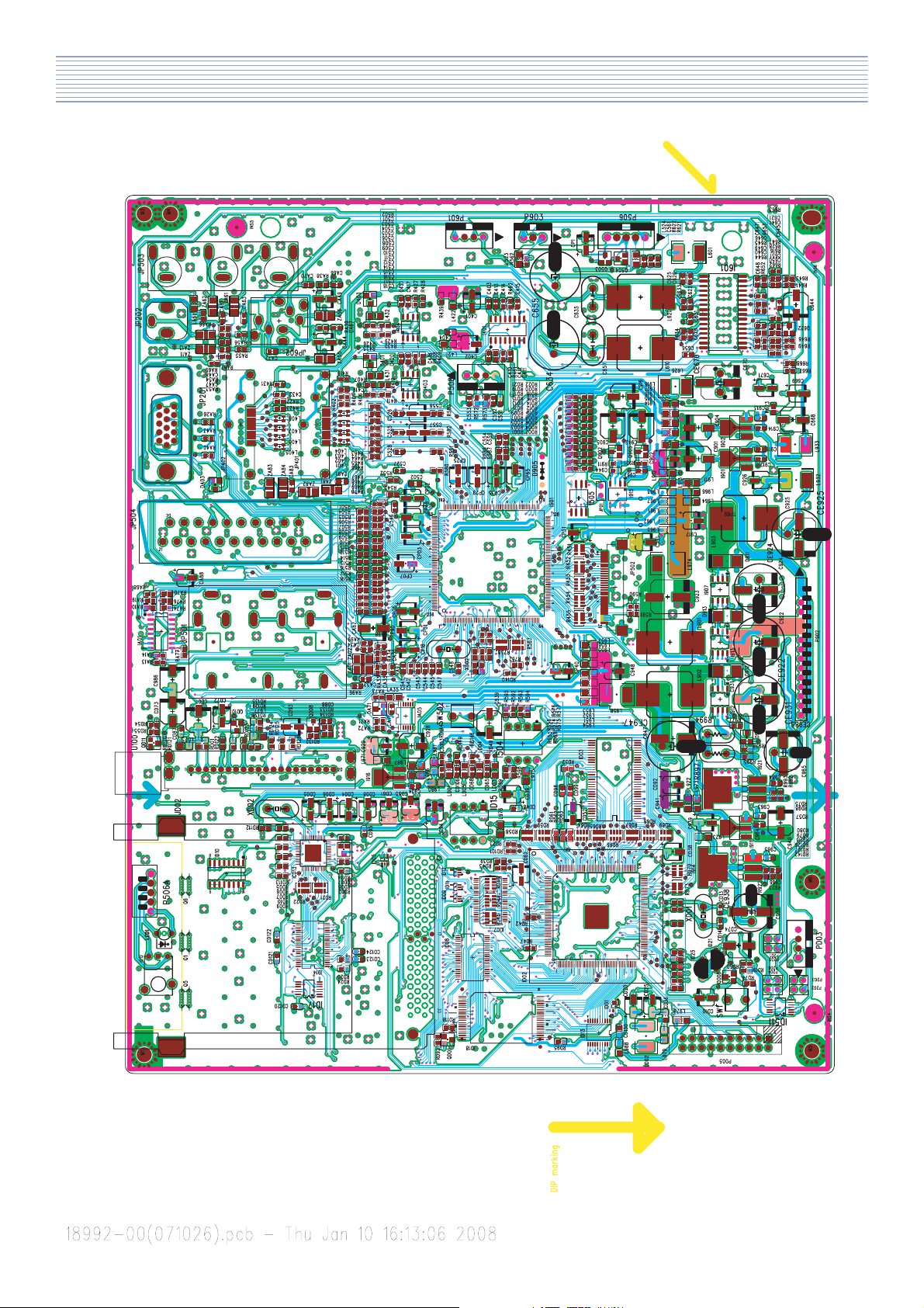
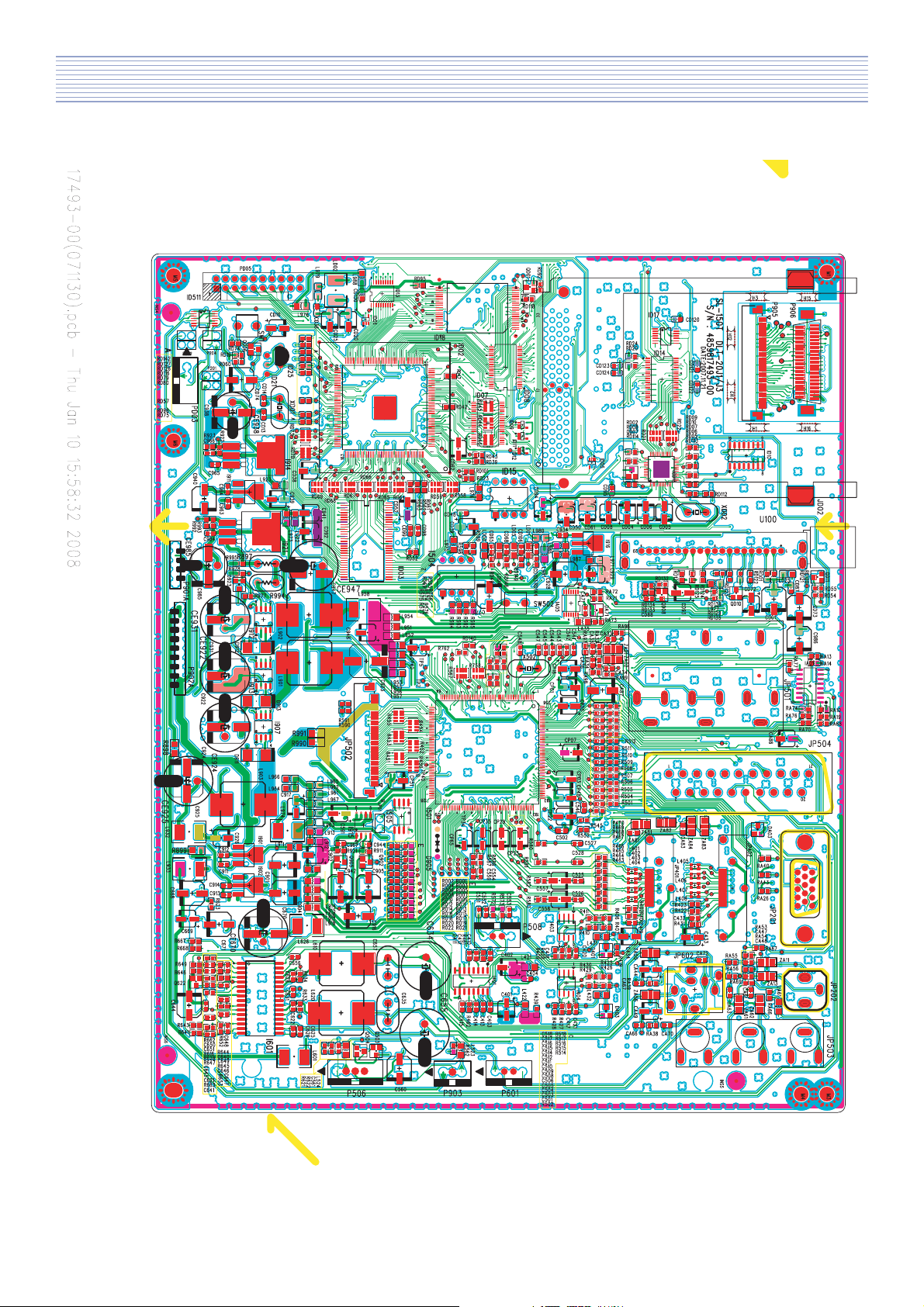
5. PCB Data (DLT-19W4, DLT-22W4 - TOP)
14
Page 16
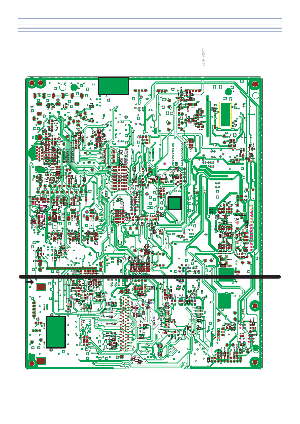
PCB Data (DLT-19W4, DLT-22W4 - BOTTOM)
15
Page 17
PCB Data (DLT-20J1, DLT-20J3 - TOP)
16
Page 18
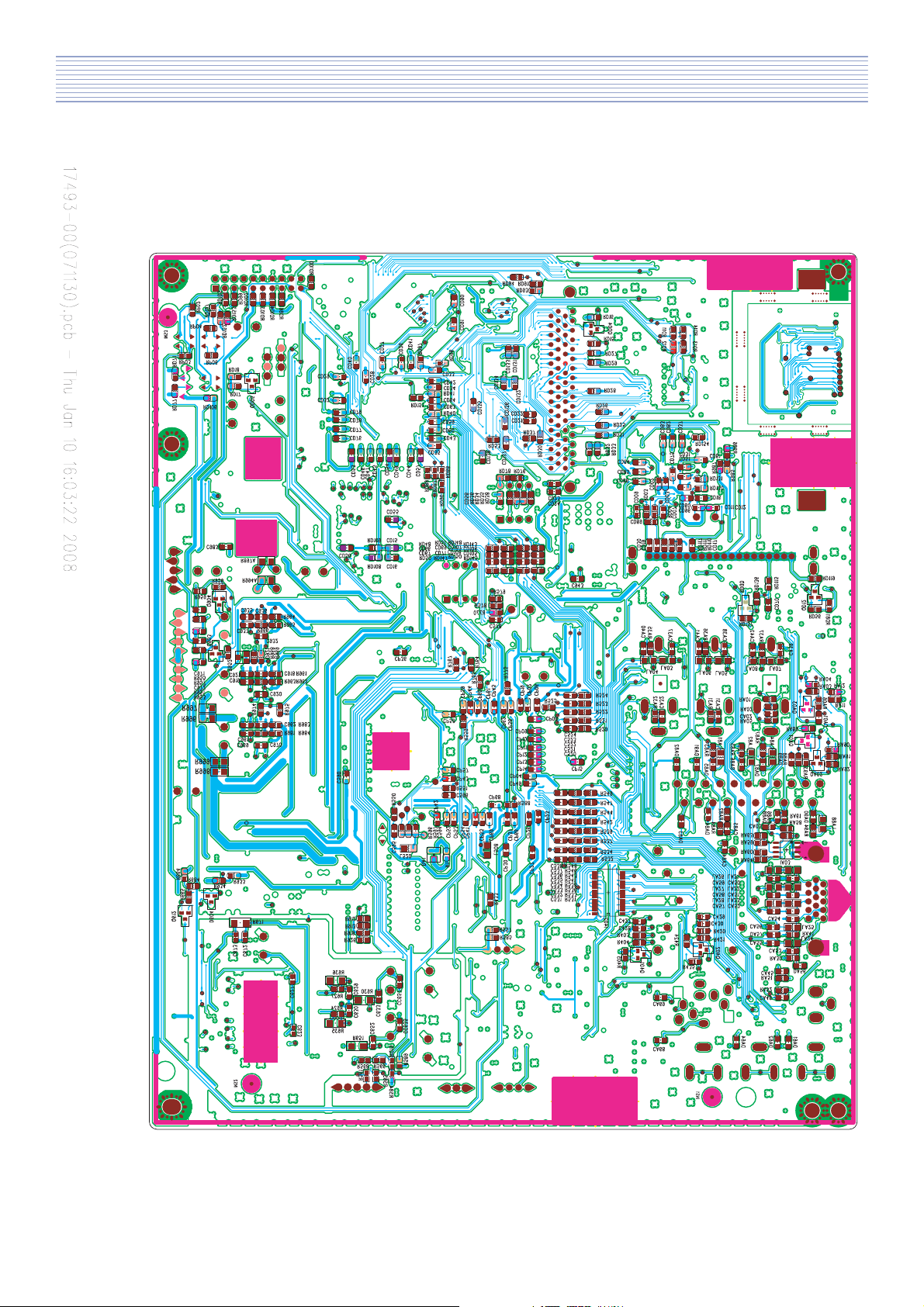
PCB Data (DLT-20J1, DLT-20J3 - BOTTOM)
17
Page 19
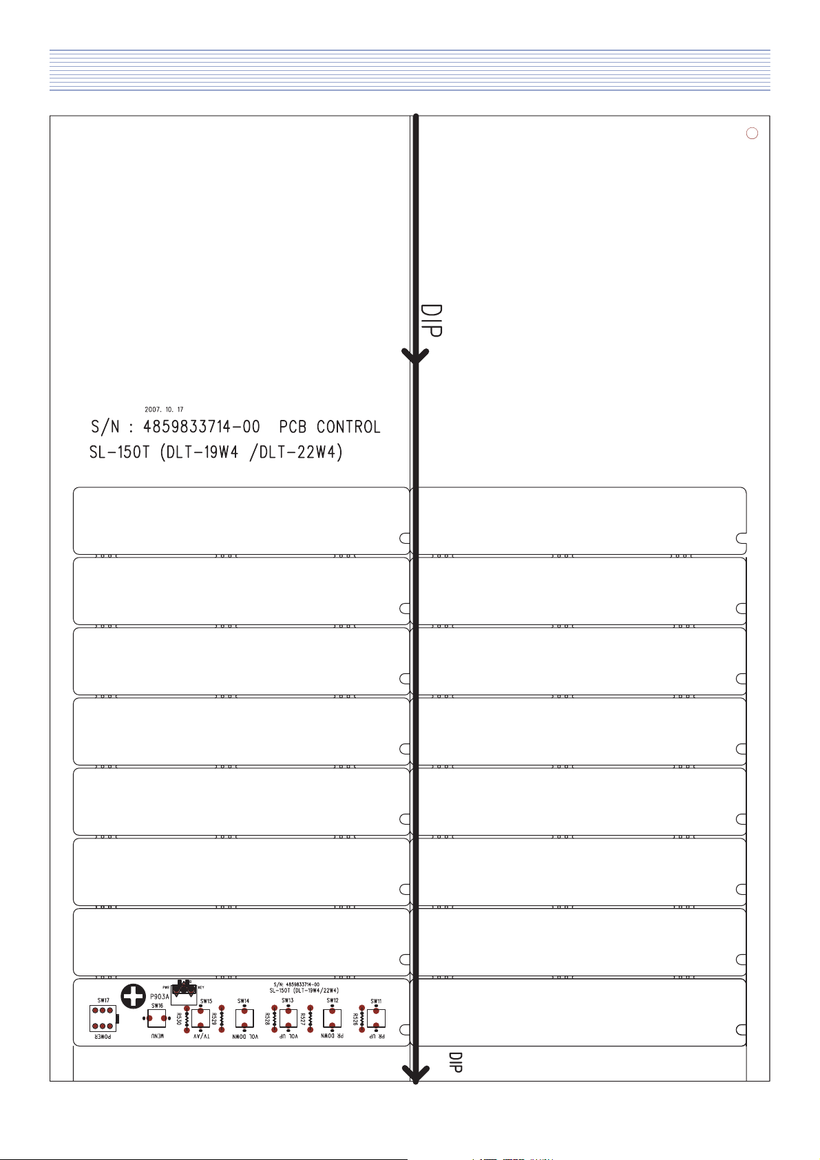
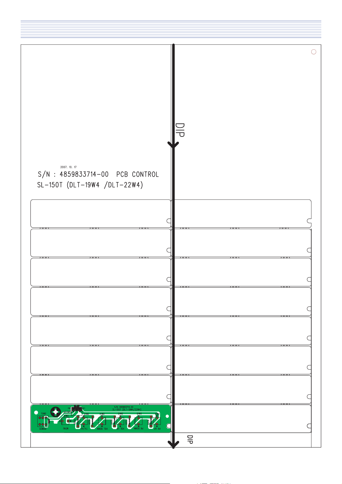
PCB Data (DLT-19W4, DLT-22W4 - Control PCB - TOP)
18
Page 20
PCB Data (DLT-19W4, DLT-22W4 - Control PCB - BOTTOM)
19
Page 21
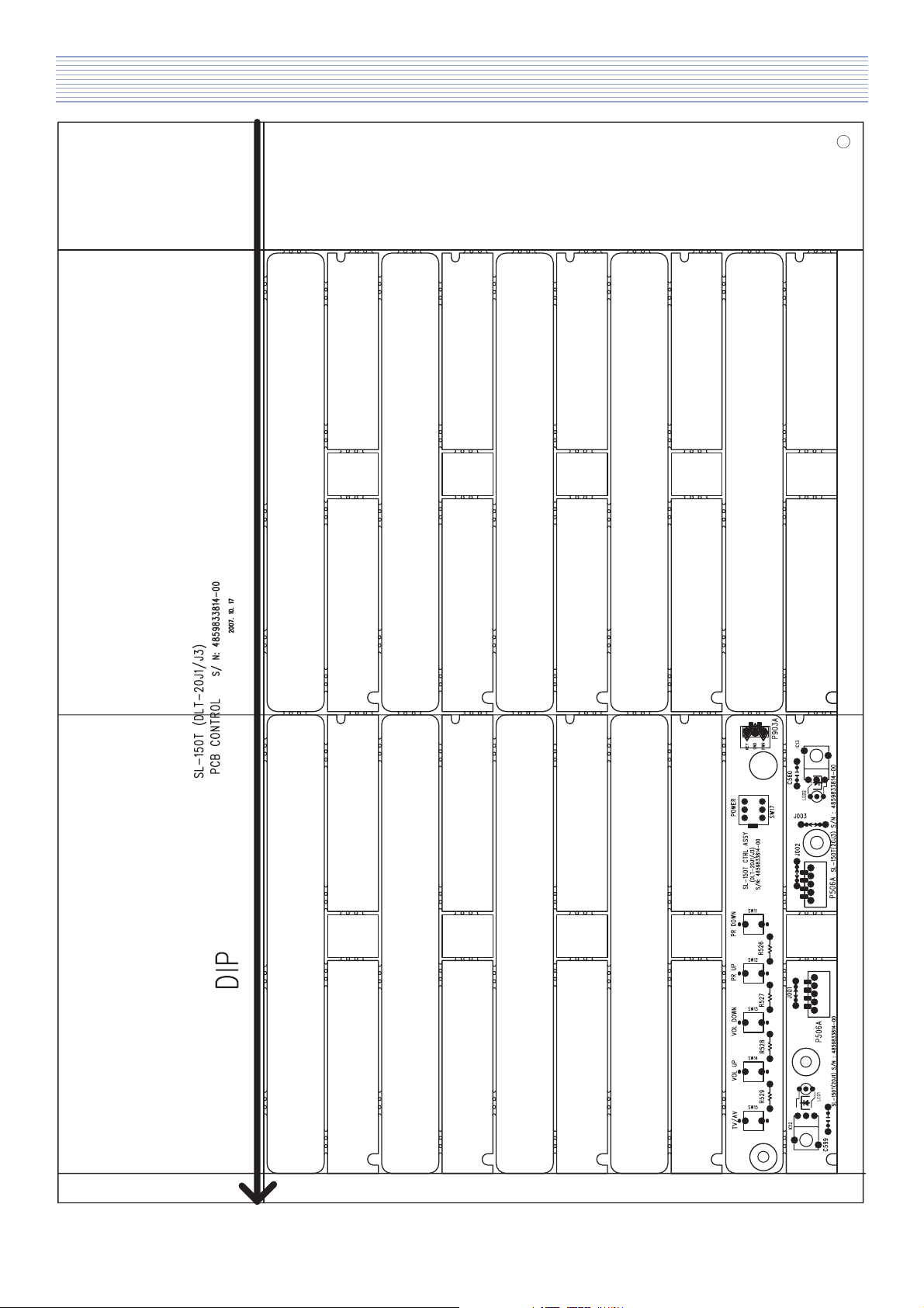
PCB Data (DLT-20J1, DLT-20J3 - Control PCB - TOP )
20
Page 22
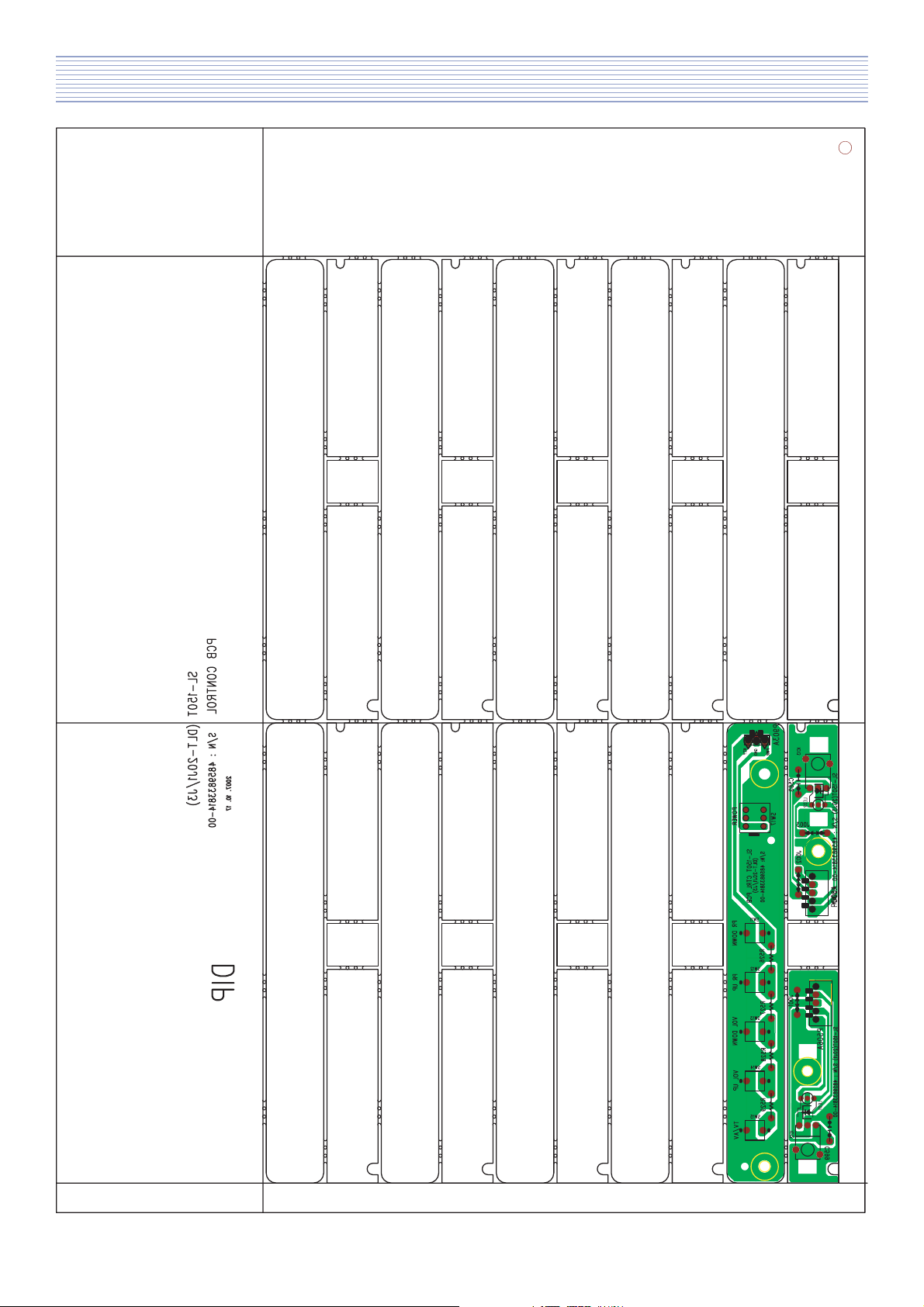
PCB Data (DLT-20J1, DLT-20J3 - Control PCB - BOTTOM)
21
Page 23

6. Trouble Shooting
* Facts you must know at trouble diagnosis or repairing
(1) The trouble diagnosis and repairing of set means Module .
In other words, find out which PCB modules are not working and replace them with normal PCB
modules.
(2) This TROUBLE SHOOTING list only contains representative and simple PCB trouble diagnosis and
Module Exchange method. Therefore, if you find Sets which are difficult to diagnose or to repair,
contact Daewoo Electronics.
(3) Basic TROUBLE SHOOTING procedure :
Check Trouble Symptoms Detach Back Cover Trouble Diagnosis Replace broken PCB module
Adjust ADC Function Check Repair Complete.
(4) Required equipments for trouble diagnosis
- Digital Multi-meter (measure Dc voltage, measure Diode Voltage, Short-Open test)
- Screwdriver (or electric screwdriver), plastic adjusting tool
(5) Before assemble/disassemble PCBs, check to see if AC Switch is OFF.
(6) After Back cover is closed, redo Heat-run for at least one hour by inputting Full white pattern.
Symptoms of power, inverter, panel Trouble
<Symptom.1> Not even weak discharge (luminescence) shows on screen.
<Symptom.2> Discharge (luminescence) on screen is unstable
<Symptom.3> Set is producing unusual noise Symptoms of VIDEO or JACK PCB Trouble
<Symptom.1> Only weak discharge (luminescence) shows on screen, but No Data is on screen
<Symptom.2> Screen DATA is abnormal
<Symptom.3> Particular input signal (Video, etc.) does not operate
<Symptom.4> No SOUND
<Symptom.5> Remote Control or KEY does not operate
22
Page 24

Trouble Shooting
6-1. When LED doesn’t lit.
Check start
Y
Is the AC power cord
correctly connected?
Y
Is power S/W ON?
Y
N
N
Confirm power cord
connection.
Confirm Power S/W ON.
Is output voltage of
Power LIPS correct?
Y
Check the Main PCB.
N
23
Check the power connection.
Exchange the power LIPS.
Page 25

Trouble Shooting
6-2. When TV doesn’t turn on in red LED.
Check start
Y
Does TV turn on
pushing the CH key?
Y
Check the connection to IR PCB.
Check the operation of Remote
Controller.
N
6-3. When “white screen”.
Check start
Y
Is output voltage of
Power module correct?
(or LIPS)
Y
Confirm Power S/W ON.
N
Check the power connection.
Exchange the Power module.
Is correctly
connected?
Y
Is normal?
Y
Check the connector or Main PCB
N
N
Check the connection
Of Panel
Check the Main PCB
24
Page 26

Trouble Shooting
6-4. When “No picture” in TV mode.
Check start
Y
Does LED turn on in
GREEN?
Y
Does raster appear?
Y
Does auto - tuning
Function operate
normally?
N
N
Go to chap 7 - 2
Is this weak discharge
On the screen?
Y
Check I501
Confirm AC connection.
N
Confirm Power SW ON.
Check the power,
Inverter and panel
Y
Tune the channel
Check the tuner
N
25
Page 27

Trouble Shooting
6-5. When “No picture” in External input mode.
Check start
Y
Does OSD menu
Screen appear?
Y
Is the signal jack
Correctly connected?
Y
Does input source
operate?
Y
Confirm AC connection.
N
N
N
Is this weak discharge
On the screen?
Check the
Connection of Jack
Operate AV device
N
Y
Confirm Power SW ON.
Check the power,
Inverter and panel
Go to 7 - 4
Is input selection
In used mode?
Y
Check the main PCB
and sub - JACK PCB
N
Confirm input selection
26
Page 28

Trouble Shooting
6-6. When No Sound in External input mode.
Check start
Y
Does Screen appear?
Y
Is the sound input jack
Correctly connected?
Y
Is the speaker jack
Correctly connected?
N
N
Connection of sound Jack
N
Connection of speaker
Go to 7-5
Check the
Check the
Y
Is the I601 output
Normal?
Y
Exchange speaker or
speak cable
N
27
Check the AUDIO AMP(I601)
And I501
Page 29

Trouble Shooting
6-7. When Key does not operate.
Check start
Y
Does remote
Controller operate?
Y
Is 2th PIN of P903A
Correctly operate?
Y
Check Key cable and I501
N
N
Check the I501
Exchange Key PCB
28
Page 30

Trouble Shooting
6-8. When Remote Controller does not operate.
Check start
Y
Does input of key
operate?
Y
Does remote
Controller operate?
Y
Whenever push the button of
Remote controller, does the 2nd pin
Of P506A output normal?
Y
N
N
N
Check the I501
Check the battery of
remote controller
Exchange the Key PCB
Check IR cable and I501
Output of 2nd pin of P501A (IR) : PCB for Remote Control EX) Push “PR DOWN” button.
29
Page 31

7. Service part list (DLT-19W4)
LOC PART CODE
ZZ110 PTACPWG105
10 4850Q00910
20 7178301251
M382A 7172401452
M382B DMP2505200
M821 4858213801
ZZ100 48B5655H1101
ZZ120 PTBCSHG105
M211 4852181401
M211A 4857823900
M211B 4857823900
M321 4853298800
ZZ130 PTPKCPG105B
M191 485819E500
M212 485218151101
M212A 4852716201
M382 485383321101
M801 DMP5030700
M822 DMP2504300
ZZ140 PTCACAG108B
M191 4851959800
M191A 7172401452
M211B 2TF01612CL
M351 4853535500
M361 4853636301
M362 485363530101
M362A 7178301052
M381C 4956800200
M381D 7172401252
M381E 7008300651
M381F 4856815910
P502A 4859000260
PWC1 48599DL002
V901 485LD16191
ZZ200 PTFMSJG105B
PART NAME PART DESCRIPTION
ACCESSORY AS DLT-19W4LMBSCF
BATTERY AAA R03 SUPERGARD/ROCKET
SCREW TAPPTITE TT2 WAS 3X12 MFZN 3CR
SCREW TAPPTITE TT2 TRS 4X14 MFZN BK 3CR
BAG P.E. P.E 40X60 DLT-19/22W4
BAG INSTRUC-
L. D. P. E. T0. 05X250X400
TION
TRANSMITTER
R-55H11 (AAA)
REMOCON
COVER BACK AS DLT-19W4LMBSCF
COVER BACK 19W4 HIPS BK
CLOTH BLACK FELT 240X12XT1.0
CLOTH BLACK FELT 240X12XT1.0
BRKT VESA 19/22W4 SECC T=1.0
PACKING AS
DLT-19W4SMB-CF
PACKING
PAD 19W4 EPS
COVER STAND
19/22W4 HIPS BK9604BP
BASE
LEG BOTTOM CR (14V5)
FRAME STAND 19/22W4 HIPS BK9604
BOX DLT-19W4TB
BAG P.E. PE FOAM T0.5X700X650
CABINET AS AS-
DLT-19W4SMB-CF
SEMBLY
HINGE AS 19/22W4
SCREW TAPPTITE TT2 TRS 4X14 MFZN BK 3CR
TAPE FILAMENT 12MMX55ME CLEAR
HOLDER AC
14A5 NYLON66 UL/CSA
CORD
TERMINAL JACK 19/22W4 HIPS BK
TERMINAL COVER HIPS BK
SCREW TAPPTITE TT2 WAS 3X10 MFZN BK 3CR
CLAMP WIRE WS-A-2-19
SCREW TAPPTITE TT2 TRS 4X12 MFZN BK 3CR
SCREW MACHINE WAS 3X6 MFZN 3CR
CLAMP WIRE EGI T0.4+TUBE+PIE 4.2
CABLE LVDS FMW1214A-31+FH10001-
30+UL1571#30=250MM
CORD POWER W/F 6-LO (LOMAX) YH396-43V
LCD PANEL LTM190M2-L31
MASK FRONT AS DLT-19W4SMB-CF
LOC PART CODE
M201 4852098411
M201A 4857818506
M201D 2233039604
M201E 48558000A02T
M561 48556192SD02
M591 485594900001
ZZ210 PTSPPWG105
P601A 4850704S41
SP01 4858319910
SP01A 4853956801
SP01B 7178301051
SP01C 4857818705
SP01D 4857818705
SP02 4858319910
SP02A 4853956801
SP02B 7178301051
SP02C 4857818705
SP02D 4857818705
ZZ280 PTCTMSG105
M231 4852335301
M481 4854873411
M491 4854965611
M491A 7178301051
P903A 4850703S70
SW17 5S40101009
ZZ200 PTCTJRG105
SW11 5S50101Z90
SW12 5S50101Z90
SW13 5S50101Z90
SW14 5S50101Z90
SW15 5S50101Z90
SW16 5S50101Z90
ZZ200 PTCTJAG105
A002 4859833714
R526 RD-AZ102J-
R527 RD-AZ122J-
R528 RD-AZ202J-
R529 RD-AZ332J-
R530 RD-AZ822J-
ZZ290 PTMPMSG108
10 2193110032
20 2193011612
30 2291050620
40 2291050314
C634 CEXF1E471V
PART NAME PART DESCRIPTION
MASK FRONT 19W4 HIPS BK
CLOTH BLACK CLOTH 240X8XT0.5
PAINT WATER BK9604BP CETELON
LABEL POP GLOSSY PET
MARK BRAND DAEWOO 68MM (20”21”)
DECO PLATE 19W4 PC T2.0
SPEAKER AS DLT-19W4LMBSCF
CONNECTOR YH025-04+YRT205+ULW=300
SPEAKER SP-5090F24C
BRKT SPKR 19/22W4 HIPS BK
SCREW TAPPTITE TT2 WAS 3X10 MFZN 3CR
CLOTH BLACK FELT T0.7 L=110 W=15
CLOTH BLACK FELT T0.7 L=110 W=15
SPEAKER SP-5090F24C
BRKT SPKR 19/22W4 HIPS BK
SCREW TAPPTITE TT2 WAS 3X10 MFZN 3CR
CLOTH BLACK FELT T0.7 L=110 W=15
CLOTH BLACK FELT T0.7 L=110 W=15
PCB CTRL
DLT-19W4LMBSCF
MANUAL AS
PANEL CTRL 19/22W4 HIPS BK
BUTTON POWER 19/22W4 ABS
GY340A+SV2405BP
BUTTON CH 19/22W4 ABS
GY340A+SV2405BP
SCREW TAPPTITE TT2 WAS 3X10 MFZN 3CR
CONNECTOR YH025-03+YBH250-
03+ULW=400
SW PUSH PS-22E06
PCB CTRL RADIAL ASDLT-19W4LMBSCF
SW TACT SKHV10910A
SW TACT SKHV10910A
SW TACT SKHV10910A
SW TACT SKHV10910A
SW TACT SKHV10910A
SW TACT SKHV10910A
PCB CTRL AXIAL ASDLT-19W4LMBSCF
PCB CONTROL SL-150T 115X23(246X330/
2X8)D1B
R CARBON FILM 1/6 1K OHM J
R CARBON FILM 1/6 1.2K OHM J
R CARBON FILM 1/6 2K OHM J
R CARBON FILM 1/6 3.3K OHM J
R CARBON FILM 1/6 8.2K OHM J
PCB MAIN
DLT-19W4SMBSCF
MANUAL AS
SOLDER WIRE SP001 PHI 3.0MM (LFCO-W3.0)
SOLDER WIRE LFC-107 (1.6MM)
FLUX SOLDER DF-2810U (0.810)
FLUX SOLVENT IM-1000
C ELECTRO 25V RSS 470MF (10X16) TP
30
Page 32

Service part list (DLT-19W4)
LOC PART CODE
C635
C655
C657
CE670
CE922
CE924
CE925
CE931
CE947
CE985
D905
I504
IC12
ID15
ID25
JD02
JP01
JP201
JP202
JP501
JP503
JP504
JP602
LED1
M381
M381A
M381B
P201
P202
P202A
P202B
P204
P204A
P204B
P506
P506A
P508
P601
P902A
P903
PD03
R897
R994
S101
S102
SW1
SW502
U100
V902
CMXL1J334J C MYLAR 63V 0.33MF J MEU TP
CEXF1E471V C ELECTRO 25V RSS 470MF (10X16) TP
CMXL1J334J C MYLAR 63V 0.33MF J MEU TP
CEXF1H221V C ELECTRO 50V RSS 220MF (10X16) TP
CEXF1C471V C ELECTRO 16V RSS 470MF (10X12.5)TP
CEXF1C471V C ELECTRO 16V RSS 470MF (10X12.5)TP
CEXF1C471V C ELECTRO 16V RSS 470MF (10X12.5)TP
CEXF1C471V C ELECTRO 16V RSS 470MF (10X12.5)TP
CEXF1C471V C ELECTRO 16V RSS 470MF (10X12.5)TP
CEXF1C471V C ELECTRO 16V RSS 470MF (10X12.5)TP
DBAT85---- DIODE BAT85 (TAPPING)
1M24C32BN6 IC EEPROM M24C32WRNG
1R24FH1B-- IC PREAMP R24FH1B
14C64WBN6- IC EEPROM M24C64-WBN6
1K1A7025AP IC RESET KIA7025AP
4859200440 CONN PCMCIA PC68PRA5513XZ
4859295520 CONN WAFER 4602-02MV2-60-1 PLUG 2P ST
4959200160 CONN D-SUB SHF-015-B111-22/BR2-J0.6
4959102340 JACK PHONE YKB21-5157
4859117750 JACK PIN TPSE-9612-6
4859112850 JACK PIN DPSS-0173 3PIN STR
4859112950 JACK SCART DSSM-0378 STR
97P6316100 JACK HEAD
DSPR39MVW- LED SPR-39MVW (DUAL)
4853833301 FRAME MAIN PCB 19W4 SECC T0.8 (SEC)
7178300852 SCREW TAPTITE TT2 WAS 3X8 MFZN BK 3CR
7178300852 SCREW TAPTITE TT2 WAS 3X8 MFZN BK 3CR
4859295420 CONN WAFER 4602-04MV2-1 PLUG 4P ST
4859295420 CONN WAFER 4602-04MV2-1 PLUG 4P ST
4859295620 CONN WAFER 4602-2FV2-1 JUMPER 2P 2.54
4859295620 CONN WAFER 4602-2FV2-1 JUMPER 2P 2.54
4859295420 CONN WAFER 4602-04MV2-1 PLUG 4P ST
4859295620 CONN WAFER 4602-2FV2-1 JUMPER 2P 2.54
4859295620 CONN WAFER 4602-2FV2-1 JUMPER 2P 2.54
4859231820 CONN WAFER Y W025-05
4850705S32 CONNECTOR YH025-05+YBH250-
485923172S CONN WAFER YW025-04 (STICK )
485923172S CONN WAFER YW025-04 (STICK )
4850715N09 CONNECTOR YH025-15+YBNH250-
4859231620 CONN WAFER Y W025-03
485923172S CONN WAFER YW025-04 (STICK )
RN02B399JS R METAL FILM 2W 3.9 OHM J SMALL
RN02B399JS R METAL FILM 2W 3.9 OHM J SMALL
485A115170 SHIELDRON 12X20X10(H)
485A115170 SHIELDRON 12X20X10(H)
5S50101Z90 SW TACT SKHV10910A
5S50101Z90 SW TACT SKHV10910A
4859732130 TUNER DIGITAL TDTG-S154D
485AS003PL POWER LIPS IPB-6012M01
PART NAME PART DESCRIPTION
DHSE-9959
PHONE
05+ULW=350
15+ULW=100
LOC PART CODE
PART NAME PART DESCRIPTION
X502 5XJX19R6JE CRYSTAL QUARTZ HC-49/S 19.6608MHZ 18PF
30PPM
XD01 5XJ27R00AC CRYSTAL QUARTZ HC-49/S 27.000MHZ 15PF
20PPM
XD02 5XJ27R00AC CRYSTAL QUARTZ HC-49/S 27.000MHZ 15PF
20PPM
ZZ200 PTMPJ2G105 PCB CHIP MOUNT
DLT-19W4LMBSCF
B AS
C520 HCBK104KBA C CHIP CERA 50V X7R 0.1MF K 1608
C521 HCBK104KBA C CHIP CERA 50V X7R 0.1MF K 1608
C522 HCBK104KBA C CHIP CERA 50V X7R 0.1MF K 1608
C523 HCBK104KBA C CHIP CERA 50V X7R 0.1MF K 1608
C524 HCBK104KBA C CHIP CERA 50V X7R 0.1MF K 1608
C531 HCBF224KBA C CHIP CERA 16V X7R 0.22MF K 1608
C532 HCBF224KBA C CHIP CERA 16V X7R 0.22MF K 1608
C533 HCBF224KBA C CHIP CERA 16V X7R 0.22MF K 1608
C534 HCBF224KBA C CHIP CERA 16V X7R 0.22MF K 1608
C535 HCBF224KBA C CHIP CERA 16V X7R 0.22MF K 1608
C536 HCBF224KBA C CHIP CERA 16V X7R 0.22MF K 1608
C537 HCBF224KBA C CHIP CERA 16V X7R 0.22MF K 1608
C538 HCBF224KBA C CHIP CERA 16V X7R 0.22MF K 1608
C578 HCBK103KBA C CHIP CERA 50V X7R 0.01MF K 1608
C590 HCBK104KBA C CHIP CERA 50V X7R 0.1MF K 1608
C594 HCBK104KBA C CHIP CERA 50V X7R 0.1MF K 1608
C623 HCBK104KBA C CHIP CERA 50V X7R 0.1MF K 1608
C627 HCBK104KBA C CHIP CERA 50V X7R 0.1MF K 1608
C629 HCQK471JBA C CHIP CERA 50V CH 470PF J 1608
C630 HCQK471JBA C CHIP CERA 50V CH 470PF J 1608
C633 HCBK104KBA C CHIP CERA 50V X7R 0.1MF K 1608
C652 HCBK104KBA C CHIP CERA 50V X7R 0.1MF K 1608
C672 HCBK104KBA C CHIP CERA 50V X7R 0.1MF K 1608
C673 HCBK104KBA C CHIP CERA 50V X7R 0.1MF K 1608
C919 HCBK103KBA C CHIP CERA 50V X7R 0.01MF K 1608
C920 HCBK103KBA C CHIP CERA 50V X7R 0.01MF K 1608
C921 HCBK104KBA C CHIP CERA 50V X7R 0.1MF K 1608
C932 HCBK103KBA C CHIP CERA 50V X7R 0.01MF K 1608
C935 HCBK104KBA C CHIP CERA 50V X7R 0.1MF K 1608
C937 HCBK153KBA C CHIP CERA 50V X7R 0.015MF K 1608
C943 HCBK104KBA C CHIP CERA 50V X7R 0.1MF K 1608
C961 HCBK104KBA C CHIP CERA 50V X7R 0.1MF K 1608
C969 HCBK223KBA C CHIP CERA 50V X7R 0.022MF K 1608
C970 HCBK103KBA C CHIP CERA 50V X7R 0.01MF K 1608
C971 HCBK104KBA C CHIP CERA 50V X7R 0.1MF K 1608
C972 HCBK104KBA C CHIP CERA 50V X7R 0.1MF K 1608
C983 HCBK104KBA C CHIP CERA 50V X7R 0.1MF K 1608
CA01 HCBK104KBA C CHIP CERA 50V X7R 0.1MF K 1608
CA02 HCBK103KBA C CHIP CERA 50V X7R 0.01MF K 1608
CA03 HCBK104KBA C CHIP CERA 50V X7R 0.1MF K 1608
CA31 HCBK102KBA C CHIP CERA 50V X7R 1000PF K 1608
CA32 HCBK102KBA C CHIP CERA 50V X7R 1000PF K 1608
CA37 HCQK120JBA C CHIP CERA 50V CH 12PF J 1608
CA38 HCQK120JBA C CHIP CERA 50V CH 12PF J 1608
CA39 HCQK120JBA C CHIP CERA 50V CH 12PF J 1608
31
Page 33

Service part list (DLT-19W4)
LOC PART CODE
CA40 HCQK120JBA C CHIP CERA 50V CH 12PF J 1608
CA41 HCQK120JBA C CHIP CERA 50V CH 12PF J 1608
CA42 HCQK120JBA C CHIP CERA 50V CH 12PF J 1608
CA45 HCBK102KBA C CHIP CERA 50V X7R 1000PF K 1608
CA46 HCBK102KBA C CHIP CERA 50V X7R 1000PF K 1608
CA50 HCQK120JBA C CHIP CERA 50V CH 12PF J 1608
CA51 HCQK120JBA C CHIP CERA 50V CH 12PF J 1608
CA52 HCQK120JBA C CHIP CERA 50V CH 12PF J 1608
CA53 HCQK470JBA C CHIP CERA 50V CH 47PF J 1608
CA54 HCQK470JBA C CHIP CERA 50V CH 47PF J 1608
CA55 HCQK120JBA C CHIP CERA 50V CH 12PF J 1608
CA56 HCQK120JBA C CHIP CERA 50V CH 12PF J 1608
CA57 HCQK120JBA C CHIP CERA 50V CH 12PF J 1608
CA58 HCQK120JBA C CHIP CERA 50V CH 12PF J 1608
CA59 HCQK120JBA C CHIP CERA 50V CH 12PF J 1608
CA68 HCBK104KBA C CHIP CERA 50V X7R 0.1MF K 1608
CA69 HCBK104KBA C CHIP CERA 50V X7R 0.1MF K 1608
CA84 HCBK102KBA C CHIP CERA 50V X7R 1000PF K 1608
CD02 HCBK104KBA C CHIP CERA 50V X7R 0.1MF K 1608
CD03 HCBK102KBA C CHIP CERA 50V X7R 1000PF K 1608
CD07 HCBK104KBA C CHIP CERA 50V X7R 0.1MF K 1608
CD09 HCBK104KBA C CHIP CERA 50V X7R 0.1MF K 1608
CD105 HCQK391JBA C CHIP CERA 50V CH 390PF J 1608
CD108 HCQK391JBA C CHIP CERA 50V CH 390PF J 1608
CD11 HCQK150JBA C CHIP CERA 50V CH 15PF J 1608
CD12 HCQK150JBA C CHIP CERA 50V CH 15PF J 1608
CD131 HCBK104KBA C CHIP CERA 50V X7R 0.1MF K 1608
CD132 HCBK104KBA C CHIP CERA 50V X7R 0.1MF K 1608
CD133 HCBK104KBA C CHIP CERA 50V X7R 0.1MF K 1608
CD134 HCBK104KBA C CHIP CERA 50V X7R 0.1MF K 1608
CD135 HCBK104KBA C CHIP CERA 50V X7R 0.1MF K 1608
CD136 HCBK104KBA C CHIP CERA 50V X7R 0.1MF K 1608
CD137 HCBK104KBA C CHIP CERA 50V X7R 0.1MF K 1608
CD138 HCBK104KBA C CHIP CERA 50V X7R 0.1MF K 1608
CD15 HCBK104KBA C CHIP CERA 50V X7R 0.1MF K 1608
CD16 HCBK104KBA C CHIP CERA 50V X7R 0.1MF K 1608
CD17 HCBK104KBA C CHIP CERA 50V X7R 0.1MF K 1608
CD19 HCBK102KBA C CHIP CERA 50V X7R 1000PF K 1608
CD21 HCBK104KBA C CHIP CERA 50V X7R 0.1MF K 1608
CD22 HCBK104KBA C CHIP CERA 50V X7R 0.1MF K 1608
CD23 HCBK104KBA C CHIP CERA 50V X7R 0.1MF K 1608
CD24 HCBK104KBA C CHIP CERA 50V X7R 0.1MF K 1608
CD26 HCBK104KBA C CHIP CERA 50V X7R 0.1MF K 1608
CD27 HCBK104KBA C CHIP CERA 50V X7R 0.1MF K 1608
CD28 HCBK104KBA C CHIP CERA 50V X7R 0.1MF K 1608
CD29 HCBK104KBA C CHIP CERA 50V X7R 0.1MF K 1608
CD30 HCBK102KBA C CHIP CERA 50V X7R 1000PF K 1608
CD31 HCBK104KBA C CHIP CERA 50V X7R 0.1MF K 1608
CD32 HCBK104KBA C CHIP CERA 50V X7R 0.1MF K 1608
CD33 HCBK104KBA C CHIP CERA 50V X7R 0.1MF K 1608
CD34 HCBK104KBA C CHIP CERA 50V X7R 0.1MF K 1608
CD35 HCBK104KBA C CHIP CERA 50V X7R 0.1MF K 1608
PART NAME PART DESCRIPTION
LOC PART CODE
CD37 HCBK104KBA C CHIP CERA 50V X7R 0.1MF K 1608
CD40 HCBK104KBA C CHIP CERA 50V X7R 0.1MF K 1608
CD41 HCBK104KBA C CHIP CERA 50V X7R 0.1MF K 1608
CD42 HCBK104KBA C CHIP CERA 50V X7R 0.1MF K 1608
CD43 HCBK104KBA C CHIP CERA 50V X7R 0.1MF K 1608
CD44 HCBK104KBA C CHIP CERA 50V X7R 0.1MF K 1608
CD45 HCBK104KBA C CHIP CERA 50V X7R 0.1MF K 1608
CD46 HCBK104KBA C CHIP CERA 50V X7R 0.1MF K 1608
CD47 HCBK104KBA C CHIP CERA 50V X7R 0.1MF K 1608
CD49 HCBK104KBA C CHIP CERA 50V X7R 0.1MF K 1608
CD51 HCBK104KBA C CHIP CERA 50V X7R 0.1MF K 1608
CD53 HCBK104KBA C CHIP CERA 50V X7R 0.1MF K 1608
CD54 HCBK104KBA C CHIP CERA 50V X7R 0.1MF K 1608
CD55 HCBK104KBA C CHIP CERA 50V X7R 0.1MF K 1608
CD56 HCBK104KBA C CHIP CERA 50V X7R 0.1MF K 1608
CD57 HCBK104KBA C CHIP CERA 50V X7R 0.1MF K 1608
CD58 HCBK104KBA C CHIP CERA 50V X7R 0.1MF K 1608
CD59 HCBK104KBA C CHIP CERA 50V X7R 0.1MF K 1608
CD60 HCBK103KBA C CHIP CERA 50V X7R 0.01MF K 1608
CD63 HCBK104KBA C CHIP CERA 50V X7R 0.1MF K 1608
CD64 HCBK103KBA C CHIP CERA 50V X7R 0.01MF K 1608
CD67 HCQK391JBA C CHIP CERA 50V CH 390PF J 1608
CD70 HCBF224KBA C CHIP CERA 16V X7R 0.22MF K 1608
CD71 HCQK391JBA C CHIP CERA 50V CH 390PF J 1608
CD75 HCBK104KBA C CHIP CERA 50V X7R 0.1MF K 1608
CD76 HCBK102KBA C CHIP CERA 50V X7R 1000PF K 1608
CD77 HCBK104KBA C CHIP CERA 50V X7R 0.1MF K 1608
CD78 HCBK102KBA C CHIP CERA 50V X7R 1000PF K 1608
CD79 HCBK104KBA C CHIP CERA 50V X7R 0.1MF K 1608
CD80 HCBK104KBA C CHIP CERA 50V X7R 0.1MF K 1608
CD81 HCBK104KBA C CHIP CERA 50V X7R 0.1MF K 1608
CD82 HCBK104KBA C CHIP CERA 50V X7R 0.1MF K 1608
CD83 HCBK104KBA C CHIP CERA 50V X7R 0.1MF K 1608
CD84 HCBK104KBA C CHIP CERA 50V X7R 0.1MF K 1608
CD85 HCBK104KBA C CHIP CERA 50V X7R 0.1MF K 1608
CD86 HCBK104KBA C CHIP CERA 50V X7R 0.1MF K 1608
CD90 HCBK104KBA C CHIP CERA 50V X7R 0.1MF K 1608
CD91 HCBK104KBA C CHIP CERA 50V X7R 0.1MF K 1608
CD96 HCBK104KBA C CHIP CERA 50V X7R 0.1MF K 1608
CP02 HCBK104KBA C CHIP CERA 50V X7R 0.1MF K 1608
CP04 HCBK104KBA C CHIP CERA 50V X7R 0.1MF K 1608
CP06 HCBK104KBA C CHIP CERA 50V X7R 0.1MF K 1608
CP08 HCBK104KBA C CHIP CERA 50V X7R 0.1MF K 1608
CP09 HCBK104KBA C CHIP CERA 50V X7R 0.1MF K 1608
CP10 HCBK104KBA C CHIP CERA 50V X7R 0.1MF K 1608
CP11 HCBK104KBA C CHIP CERA 50V X7R 0.1MF K 1608
CP12 HCBK104KBA C CHIP CERA 50V X7R 0.1MF K 1608
CP13 HCBK104KBA C CHIP CERA 50V X7R 0.1MF K 1608
CP14 HCBK104KBA C CHIP CERA 50V X7R 0.1MF K 1608
CP15 HCBK104KBA C CHIP CERA 50V X7R 0.1MF K 1608
CP19 HCBK104KBA C CHIP CERA 50V X7R 0.1MF K 1608
CP23 HCBK104KBA C CHIP CERA 50V X7R 0.1MF K 1608
PART NAME PART DESCRIPTION
32
Page 34

Service part list (DLT-19W4)
LOC PART CODE
R550 HRFT000JBA R CHIP 1/10 0 OHM J 1608
R551 HRFT000JBA R CHIP 1/10 0 OHM J 1608
R557 HRFT102JBA R CHIP 1/10 1K OHM J 1608
R559 HRFT101JBA R CHIP 1/10 100 OHM J 1608
R561 HRFT181JBA R CHIP 1/10 180 OHM J 1608
R566 HRFT102JBA R CHIP 1/10 1K OHM J 1608
R568 HRFT102JBA R CHIP 1/10 1K OHM J 1608
R584 HRFT000JBA R CHIP 1/10 0 OHM J 1608
R585 HRFT272JBA R CHIP 1/10 2.7K OHM J 1608
R588 HRT2490FBA R CHIP 1/10 249 OHM F 1608
R596 HRFT103JBA R CHIP 1/10 10K OHM J 1608
R597 HRFT103JBA R CHIP 1/10 10K OHM J 1608
R630 HRF4220JEA R CHIP 1/4W 22 OHM J 3216
R635 HRF4100JEA R CHIP 1/4W 10 OHM J 3216
R636 HRF4100JEA R CHIP 1/4W 10 OHM J 3216
R651 HRF4220JEA R CHIP 1/4W 22 OHM J 3216
R665 HRFT223JBA R CHIP 1/10 22K OHM J 1608
R671 HRF4100JEA R CHIP 1/4W 10 OHM J 3216
R684 HRFT153JBA R CHIP 1/10 15K OHM J 1608
R764 HRFT000JBA R CHIP 1/10 0 OHM J 1608
R770 HRFT752JBA R CHIP 1/10 7.5K OHM J 1608
R912 HRFT332JBA R CHIP 1/10 3.3K OHM J 1608
R913 HRFT103JBA R CHIP 1/10 10K OHM J 1608
R919 HRFT103JBA R CHIP 1/10 10K OHM J 1608
R926 HRFT332JBA R CHIP 1/10 3.3K OHM J 1608
R934 HRFT000JBA R CHIP 1/10 0 OHM J 1608
R951 HRFT104JBA R CHIP 1/10 100K OHM J 1608
R952 HRFT472JBA R CHIP 1/10 4.7K OHM J 1608
R953 HRFT472JBA R CHIP 1/10 4.7K OHM J 1608
R955 HRFT101JBA R CHIP 1/10 100 OHM J 1608
R956 HRFT472JBA R CHIP 1/10 4.7K OHM J 1608
R957 HRFT472JBA R CHIP 1/10 4.7K OHM J 1608
R961 HRFT512JBA R CHIP 1/10 5.1K OHM J 1608
R962 HRFT103JBA R CHIP 1/10 10K OHM J 1608
R963 HRFT103JBA R CHIP 1/10 10K OHM J 1608
R964 HRFT183JBA R CHIP 1/10 18K OHM J 1608
R965 HRFT103JBA R CHIP 1/10 10K OHM J 1608
R966 HRFT103JBA R CHIP 1/10 10K OHM J 1608
R968 HRFT103JBA R CHIP 1/10 10K OHM J 1608
R969 HRFT103JBA R CHIP 1/10 10K OHM J 1608
R974 HRFT103JBA R CHIP 1/10 10K OHM J 1608
R975 HRFT102JBA R CHIP 1/10 1K OHM J 1608
R981 HRFT103JBA R CHIP 1/10 10K OHM J 1608
R983 HRFT333JBA R CHIP 1/10 33K OHM J 1608
R984 HRFT103JBA R CHIP 1/10 10K OHM J 1608
R985 HRFT000JBA R CHIP 1/10 0 OHM J 1608
R996 HRFT000-CA R CHIP 1/10 0 OHM 2012
R997 HRFT000-CA R CHIP 1/10 0 OHM 2012
RA01 HRFT221JBA R CHIP 1/10 220 OHM J 1608
RA02 HRFT121JBA R CHIP 1/10 120 OHM J 1608
RA03 HRFT472JBA R CHIP 1/10 4.7K OHM J 1608
RA04 HRFT472JBA R CHIP 1/10 4.7K OHM J 1608
PART NAME PART DESCRIPTION
LOC PART CODE
RA05 HRFT471JBA R CHIP 1/10 470 OHM J 1608
RA06 HRFT102JBA R CHIP 1/10 1K OHM J 1608
RA30 HRFT511JBA R CHIP 1/10 510 OHM J 1608
RA31 HRFT473JBA R CHIP 1/10 47K OHM J 1608
RA32 HRFT473JBA R CHIP 1/10 47K OHM J 1608
RA35 HRFT750JBA R CHIP 1/10 75 OHM J 1608
RA36 HRFT750JBA R CHIP 1/10 75 OHM J 1608
RA37 HRFT750JBA R CHIP 1/10 75 OHM J 1608
RA41 HRFT511JBA R CHIP 1/10 510 OHM J 1608
RA51 HRFT224JBA R CHIP 1/10 220K OHM J 1608
RA52 HRFT224JBA R CHIP 1/10 220K OHM J 1608
RA59 HRFT332JBA R CHIP 1/10 3.3K OHM J 1608
RA60 HRFT332JBA R CHIP 1/10 3.3K OHM J 1608
RA61 HRFT000JBA R CHIP 1/10 0 OHM J 1608
RA63 HRFT101JBA R CHIP 1/10 100 OHM J 1608
RA64 HRFT101JBA R CHIP 1/10 100 OHM J 1608
RA82 HRFT303JBA R CHIP 1/10 30K OHM J 1608
RA83 HRFT750JBA R CHIP 1/10 75 OHM J 1608
RA84 HRFT103JBA R CHIP 1/10 10K OHM J 1608
RA85 HRFT750JBA R CHIP 1/10 75 OHM J 1608
RA86 HRFT750JBA R CHIP 1/10 75 OHM J 1608
RA87 HRFT750JBA R CHIP 1/10 75 OHM J 1608
RA88 HRFT750JBA R CHIP 1/10 75 OHM J 1608
RA89 HRFT122JBA R CHIP 1/10 1.2K OHM J 1608
RA90 HRFT393JBA R CHIP 1/10 39K OHM J 1608
RA91 HRFT223JBA R CHIP 1/10 22K OHM J 1608
RA92 HRFT681JBA R CHIP 1/10 680 OHM J 1608
RA93 HRFT681JBA R CHIP 1/10 680 OHM J 1608
RA94 HRFT750JBA R CHIP 1/10 75 OHM J 1608
RD03 HRFT471JBA R CHIP 1/10 470 OHM J 1608
RD04 HRFT471JBA R CHIP 1/10 470 OHM J 1608
RD100 HRFT103JBA R CHIP 1/10 10K OHM J 1608
RD102 HRFT103JBA R CHIP 1/10 10K OHM J 1608
RD103 HRFT103JBA R CHIP 1/10 10K OHM J 1608
RD104 HRFT103JBA R CHIP 1/10 10K OHM J 1608
RD105 HRFT101JBA R CHIP 1/10 100 OHM J 1608
RD106 HRFT000JBA R CHIP 1/10 0 OHM J 1608
RD107 HRFT101JBA R CHIP 1/10 100 OHM J 1608
RD108 HRFT102JBA R CHIP 1/10 1K OHM J 1608
RD109 HRFT102JBA R CHIP 1/10 1K OHM J 1608
RD117 HRFT000JBA R CHIP 1/10 0 OHM J 1608
RD119 HRFT000JBA R CHIP 1/10 0 OHM J 1608
RD130 HRFT472JBA R CHIP 1/10 4.7K OHM J 1608
RD131 HRFT472JBA R CHIP 1/10 4.7K OHM J 1608
RD145 HRFT151JBA R CHIP 1/10 150 OHM J 1608
RD147 HRFT151JBA R CHIP 1/10 150 OHM J 1608
RD15 HRFT103JBA R CHIP 1/10 10K OHM J 1608
RD150 HRFT151JBA R CHIP 1/10 150 OHM J 1608
RD16 HRFT103JBA R CHIP 1/10 10K OHM J 1608
RD17 HRFT472JBA R CHIP 1/10 4.7K OHM J 1608
RD18 HRFT472JBA R CHIP 1/10 4.7K OHM J 1608
RD25 HRFT103JBA R CHIP 1/10 10K OHM J 1608
PART NAME PART DESCRIPTION
33
Page 35

Service part list (DLT-19W4)
LOC PART CODE
RD26 HRFT103JBA R CHIP 1/10 10K OHM J 1608
RD27 HRFT103JBA R CHIP 1/10 10K OHM J 1608
RD28 HRFT103JBA R CHIP 1/10 10K OHM J 1608
RD29 HRFT103JBA R CHIP 1/10 10K OHM J 1608
RD30 HRFT103JBA R CHIP 1/10 10K OHM J 1608
RD31 HRFT103JBA R CHIP 1/10 10K OHM J 1608
RD32 HRFT103JBA R CHIP 1/10 10K OHM J 1608
RD33 HRFT103JBA R CHIP 1/10 10K OHM J 1608
RD34 HRFT472JBA R CHIP 1/10 4.7K OHM J 1608
RD35 HRFT472JBA R CHIP 1/10 4.7K OHM J 1608
RD36 HRFT470JBA R CHIP 1/10 47 OHM J 1608
RD37 HRFT000JBA R CHIP 1/10 0 OHM J 1608
RD38 HRFT470JBA R CHIP 1/10 47 OHM J 1608
RD40 HRFT000JBA R CHIP 1/10 0 OHM J 1608
RD41 HRFT000JBA R CHIP 1/10 0 OHM J 1608
RD50 HRFT151JBA R CHIP 1/10 150 OHM J 1608
RD53 HRFT470JBA R CHIP 1/10 47 OHM J 1608
RD56 HRFT473JBA R CHIP 1/10 47K OHM J 1608
RD76 HRFT000JBA R CHIP 1/10 0 OHM J 1608
RD91 HRFT000JBA R CHIP 1/10 0 OHM J 1608
RD93 HRFT103JBA R CHIP 1/10 10K OHM J 1608
RD96 HRFT103JBA R CHIP 1/10 10K OHM J 1608
RD97 HRFT103JBA R CHIP 1/10 10K OHM J 1608
RD99 HRFT103JBA R CHIP 1/10 10K OHM J 1608
RQ15 HRFT472JBA R CHIP 1/10 4.7K OHM J 1608
ZZ200 PTMPJ1G105 PCB CHIP MOUNT
100 2193220009 SOLDER CREAM PJ790-G0061
A001 4859818992 PCB MAIN SL-150T 234X189 K4V (WIDE)
C402 HCEJF100MC C CHIP ELECTRO 16V 10MF MV 4052
C403 HCBK104KBA C CHIP CERA 50V X7R 0.1MF K 1608
C404 HCBK104KBA C CHIP CERA 50V X7R 0.1MF K 1608
C420 HCBK104KBA C CHIP CERA 50V X7R 0.1MF K 1608
C501 HCBK104KBA C CHIP CERA 50V X7R 0.1MF K 1608
C502 HCBK104KBA C CHIP CERA 50V X7R 0.1MF K 1608
C503 HCBK104KBA C CHIP CERA 50V X7R 0.1MF K 1608
C504 HCBK104KBA C CHIP CERA 50V X7R 0.1MF K 1608
C505 HCBK104KBA C CHIP CERA 50V X7R 0.1MF K 1608
C506 HCBK104KBA C CHIP CERA 50V X7R 0.1MF K 1608
C508 HCBK104KBA C CHIP CERA 50V X7R 0.1MF K 1608
C509 HCBK104KBA C CHIP CERA 50V X7R 0.1MF K 1608
C510 HCBK104KBA C CHIP CERA 50V X7R 0.1MF K 1608
C511 HCBK104KBA C CHIP CERA 50V X7R 0.1MF K 1608
C512 HCBK104KBA C CHIP CERA 50V X7R 0.1MF K 1608
C514 HCBK104KBA C CHIP CERA 50V X7R 0.1MF K 1608
C515 HCBK104KBA C CHIP CERA 50V X7R 0.1MF K 1608
C516 HCBK104KBA C CHIP CERA 50V X7R 0.1MF K 1608
C517 HCBK104KBA C CHIP CERA 50V X7R 0.1MF K 1608
C518 HCBK104KBA C CHIP CERA 50V X7R 0.1MF K 1608
C541 HCFK103ZBA C CHIP CERA 50V Y5V 0.01MF Z 1608
C542 HCBK104KBA C CHIP CERA 50V X7R 0.1MF K 1608
C543 HCBK104KBA C CHIP CERA 50V X7R 0.1MF K 1608
PART NAME PART DESCRIPTION
DLT-19W4LMBSCF
A AS
LOC PART CODE
C544 HCBK104KBA C CHIP CERA 50V X7R 0.1MF K 1608
C545 HCBK104KBA C CHIP CERA 50V X7R 0.1MF K 1608
C547 HCQK180JBA C CHIP CERA 50V CH 18PF J 1608
C548 HCQK180JBA C CHIP CERA 50V CH 18PF J 1608
C551 HCBK104KBA C CHIP CERA 50V X7R 0.1MF K 1608
C557 HCEJK109MC C CHIP ELECTRO MV 50V 1MF 4.0DX5.3H
C558 HCEJK109MC C CHIP ELECTRO MV 50V 1MF 4.0DX5.3H
C561 HCQK221JBA C CHIP CERA 50V CH 220PF J 1608
C591 HCEJF100MC C CHIP ELECTRO 16V 10MF MV 4052
C621 HCBF224KBA C CHIP CERA 16V X7R 0.22MF K 1608
C622 HCBK153KBA C CHIP CERA 50V X7R 0.015MF K 1608
C625 HCBK104KBA C CHIP CERA 50V X7R 0.1MF K 1608
C626 HCBK104KBA C CHIP CERA 50V X7R 0.1MF K 1608
C628 HCBK153KBA C CHIP CERA 50V X7R 0.015MF K 1608
C631 HCBK104KBA C CHIP CERA 50V X7R 0.1MF K 1608
C640 HCBK104KBA C CHIP CERA 50V X7R 0.1MF K 1608
C641 HCBF224KBA C CHIP CERA 16V X7R 0.22MF K 1608
C644 HCEEF101MC C CHIP ELECTRO MV 16V 100MF 6.3DX5.7H
C645 HCBK104KBA C CHIP CERA 50V X7R 0.1MF K 1608
C646 HCBK104KBA C CHIP CERA 50V X7R 0.1MF K 1608
C647 HCQK331JBA C CHIP CERA 50V CH 330PF J 1608
C648 HCQK331JBA C CHIP CERA 50V CH 330PF J 1608
C649 HCBK104KBA C CHIP CERA 50V X7R 0.1MF K 1608
C650 HCBF224KBA C CHIP CERA 16V X7R 0.22MF K 1608
C651 HCBF224KBA C CHIP CERA 16V X7R 0.22MF K 1608
C656 HCBK104KBA C CHIP CERA 50V X7R 0.1MF K 1608
C668 HCEJF470MC C CHIP ELECTRO 16V 47MF CS 6352
C671 HCELH100MC C CHIP ELECTRO 25V 10MF CM 4052
C904 HCEEF101MC C CHIP ELECTRO MV 16V 100MF 6.3DX5.7H
C911 HCBK104KBA C CHIP CERA 50V X7R 0.1MF K 1608
C912 HCBK104KBA C CHIP CERA 50V X7R 0.1MF K 1608
C913 HCBK104KBA C CHIP CERA 50V X7R 0.1MF K 1608
C914 HCBK104KBA C CHIP CERA 50V X7R 0.1MF K 1608
C923 HCELF471ME C CHIP ELECTRO 16V 470MF CM 8010
C928 HCEEF101MC C CHIP ELECTRO MV 16V 100MF 6.3DX5.7H
C934 HCBK104KBA C CHIP CERA 50V X7R 0.1MF K 1608
C938 HCEEF101MC C CHIP ELECTRO MV 16V 100MF 6.3DX5.7H
C940 HCEEF101MC C CHIP ELECTRO MV 16V 100MF 6.3DX5.7H
C942 HCEJF470MC C CHIP ELECTRO 16V 47MF CS 6352
C944 HCBK104KBA C CHIP CERA 50V X7R 0.1MF K 1608
C963 HCBK104KBA C CHIP CERA 50V X7R 0.1MF K 1608
C964 HCBK104KBA C CHIP CERA 50V X7R 0.1MF K 1608
C965 HCBK104KBA C CHIP CERA 50V X7R 0.1MF K 1608
C966 HCBK104KBA C CHIP CERA 50V X7R 0.1MF K 1608
C967 HCBK104KBA C CHIP CERA 50V X7R 0.1MF K 1608
C984 HCBK104KBA C CHIP CERA 50V X7R 0.1MF K 1608
CA33 HCBK104KBA C CHIP CERA 50V X7R 0.1MF K 1608
CA34 HCBK104KBA C CHIP CERA 50V X7R 0.1MF K 1608
CA35 HCQK331JBA C CHIP CERA 50V CH 330PF J 1608
CA36 HCQK331JBA C CHIP CERA 50V CH 330PF J 1608
CA44 HCELK479MC C CHIP ELECTRO 50V 4.7MF CM 4052
CA47 HCBK104KBA C CHIP CERA 50V X7R 0.1MF K 1608
PART NAME PART DESCRIPTION
34
Page 36

Service part list (DLT-19W4)
LOC PART CODE
CA48 HCBK104KBA C CHIP CERA 50V X7R 0.1MF K 1608
CA49 HCELK479MC C CHIP ELECTRO 50V 4.7MF CM 4052
CA61 HCBK102KBA C CHIP CERA 50V X7R 1000PF K 1608
CA63 HCBK102KBA C CHIP CERA 50V X7R 1000PF K 1608
CA66 HCBK104KBA C CHIP CERA 50V X7R 0.1MF K 1608
CA67 HCBK104KBA C CHIP CERA 50V X7R 0.1MF K 1608
CA70 HCBK104KBA C CHIP CERA 50V X7R 0.1MF K 1608
CA71 HCBK104KBA C CHIP CERA 50V X7R 0.1MF K 1608
CA72 HCBK104KBA C CHIP CERA 50V X7R 0.1MF K 1608
CA81 HCBK102KBA C CHIP CERA 50V X7R 1000PF K 1608
CA83 HCBK102KBA C CHIP CERA 50V X7R 1000PF K 1608
CA87 HCEJF100MC C CHIP ELECTRO 16V 10MF MV 4052
CA88 HCEJF100MC C CHIP ELECTRO 16V 10MF MV 4052
CD01 HCEJF470MC C CHIP ELECTRO 16V 47MF CS 6352
CD04 HCEJK109MC C CHIP ELECTRO MV 50V 1MF 4.0DX5.3H
CD05 HCEJK109MC C CHIP ELECTRO MV 50V 1MF 4.0DX5.3H
CD06 HCEJF100MC C CHIP ELECTRO 16V 10MF MV 4052
CD08 HCEJF100MC C CHIP ELECTRO 16V 10MF MV 4052
CD10 HCELK479MC C CHIP ELECTRO 50V 4.7MF CM 4052
CD103 HCQK270JBA C CHIP CERA 50V CH 27PF J 1608
CD106 HCQK270JBA C CHIP CERA 50V CH 27PF J 1608
CD120 HCBK104KBA C CHIP CERA 50V X7R 0.1MF K 1608
CD121 HCBK104KBA C CHIP CERA 50V X7R 0.1MF K 1608
CD122 HCBK104KBA C CHIP CERA 50V X7R 0.1MF K 1608
CD123 HCBK104KBA C CHIP CERA 50V X7R 0.1MF K 1608
CD124 HCBK104KBA C CHIP CERA 50V X7R 0.1MF K 1608
CD13 HCQK220JBA C CHIP CERA 50V CH 22PF J 1608
CD130 HCBK104KBA C CHIP CERA 50V X7R 0.1MF K 1608
CD14 HCQK220JBA C CHIP CERA 50V CH 22PF J 1608
CD20 HCELF220MD C CHIP ELECTRO 16V 22MF CM 4052
CD25 HCELF220MD C CHIP ELECTRO 16V 22MF CM 4052
CD36 HCBK104KBA C CHIP CERA 50V X7R 0.1MF K 1608
CD38 HCELF220MD C CHIP ELECTRO 16V 22MF CM 4052
CD39 HCELF220MD C CHIP ELECTRO 16V 22MF CM 4052
CD48 HCBK104KBA C CHIP CERA 50V X7R 0.1MF K 1608
CD50 HCELF220MD C CHIP ELECTRO 16V 22MF CM 4052
CD52 HCELF220MD C CHIP ELECTRO 16V 22MF CM 4052
CD61 HCELF220MD C CHIP ELECTRO 16V 22MF CM 4052
CD62 HCEJK109MC C CHIP ELECTRO MV 50V 1MF 4.0DX5.3H
CD65 HCQK270JBA C CHIP CERA 50V CH 27PF J 1608
CD68 HCQK270JBA C CHIP CERA 50V CH 27PF J 1608
CD72 HCEJK109MC C CHIP ELECTRO MV 50V 1MF 4.0DX5.3H
CD74 HCELK479MC C CHIP ELECTRO 50V 4.7MF CM 4052
CD87 HCBK104KBA C CHIP CERA 50V X7R 0.1MF K 1608
CD88 HCBK104KBA C CHIP CERA 50V X7R 0.1MF K 1608
PART NAME PART DESCRIPTION
LOC PART CODE
CD92 HCELF220MD C CHIP ELECTRO 16V 22MF CM 4052
CD93 HCEJF100MC C CHIP ELECTRO 16V 10MF MV 4052
CD94 HCELF220MD C CHIP ELECTRO 16V 22MF CM 4052
CD95 HCBK104KBA C CHIP CERA 50V X7R 0.1MF K 1608
CP01 HCELF220MD C CHIP ELECTRO 16V 22MF CM 4052
CP03 HCELF220MD C CHIP ELECTRO 16V 22MF CM 4052
CP05 HCELF220MD C CHIP ELECTRO 16V 22MF CM 4052
CP07 HCELF220MD C CHIP ELECTRO 16V 22MF CM 4052
CP1 HCELF220MD C CHIP ELECTRO 16V 22MF CM 4052
CP18 HCELF220MD C CHIP ELECTRO 16V 22MF CM 4052
CP22 HCELF220MD C CHIP ELECTRO 16V 22MF CM 4052
CP25 HCELF220MD C CHIP ELECTRO 16V 22MF CM 4052
CP29 HCELF220MD C CHIP ELECTRO 16V 22MF CM 4052
CP35 HCELF220MD C CHIP ELECTRO 16V 22MF CM 4052
CP40 HCELF220MD C CHIP ELECTRO 16V 22MF CM 4052
CP48 HCELF220MD C CHIP ELECTRO 16V 22MF CM 4052
CP51 HCELF220MD C CHIP ELECTRO 16V 22MF CM 4052
CP65 HCELF220MD C CHIP ELECTRO 16V 22MF CM 4052
D401 DBAV70---B DIODE CHIP BAV70
D911 DM2FM3---C
D912 DM2FM3---C
D913 DM2FM3---C
D923 DBAV70---B DIODE CHIP BAV70
DA03 DBAV70---B DIODE CHIP BAV70
DA71 DBAV70---B DIODE CHIP BAV70
I403 124C04MN6D IC CHIP EEPROM M24C04-WMN6T
I501 1FL130602Q
I505 125VF016-Q
I601 1TDA8933-Q IC CHIP AUDIO AMP TDA8933
I902 1G9173363C IC CHIP REGULATOR G9117-33T63U 3.3V
I907 1MP1583--D IC CHIP CONVERTER MP1583DN
I911 1AZ117H25C IC CHIP REGULATOR AZ1117H-2.5TREI 2.5V
I912 1MP1583--D IC CHIP CONVERTER MP1583DN
I913 1MP1583--D IC CHIP CONVERTER MP1583DN
I914 1LM317BD2E IC CHIP REGULATOR
I915 TFDS4953-C FET CHIP FDS4953 SO-8 -30V -5A
I916 1G95110T-C IC CHIP REGULATOR G951-10T65U SOT-223
I921 1LM317BD2E IC CHIP REGULATOR
IA05 1M74HC14TC IC CHIP LOGIC M74HC14TTR
ICD13 1STV0362-Q IC CHIP CHANNEL
ID01 1C1GU04GWD IC CHIP INVERTER 74AHC1GU04GW
ID02 1ST5105--Q
ID03 11216AJTAQ IC CHIP DDR SDRAM EDD1216AJTA-5B-E
ID05 1HC1G32GWD IC CHIP OR GATE 74AHC1G32GW
PART NAME PART DESCRIPTION
DIODE CHIP SCHOTTKY
DIODE CHIP SCHOTTKY
DIODE CHIP SCHOTTKY
IC CHIP VIDEO DECODER
IC CHIP FLASH MEMORY
DECODER
IC CHIP MEDIA PROCESSOR
M2FM3 M2F TYPE
M2FM3 M2F TYPE
M2FM3 M2F TYPE
FLI30602H
SST25VF016
SOT-223
SOT-223
LM317BD2T ADJ 1.2V 37V
1.5A D2PAK
REEL
LM317BD2T ADJ 1.2V
37V 1.5A D2PAK
STV0362
ST5105
35
Page 37

Service part list (DLT-19W4)
LOC PART CODE
ID07 174LVC162D IC CHIP BUFFER 74LVC16244
ID08 174L16244D IC CHIP BUFFER 74LVTH16244
ID09 1C1GU04GWD IC CHIP INVERTER 74AHC1GU04GW
ID10 1HEF4053BD IC CHIP LOGIC HEF4053B
ID11 1HC1G32GWD IC CHIP OR GATE 74AHC1G32GW
ID12 1HC1G32GWD IC CHIP OR GATE 74AHC1G32GW
ID13 1C245APW-D IC CHIP TRANSCEIVER 74LVC245APW
ID14 174LVC162D IC CHIP BUFFER 74LVC16244
ID17 174HC126PD IC CHIP BUFFER 74HC126PW-T
ID18 1160ET70NQ IC CHIP FLASH MEMORY M29W160ET70N6T
ID511 174HC126PD IC CHIP BUFFER 74HC126PW-T
JP401 4859201660 CONN HDMI WF050-21UBR STR.
JP502 4859293820 CONN WAFER GT121-31P-TD-A
L421 HFFMMZ400A F CHIP FERRITE BEAD 40 OHM MMZ 2012S
L431 HFFMMZ400A F CHIP FERRITE BEAD 40 OHM MMZ 2012S
L432 HFFMMZ400A F CHIP FERRITE BEAD 40 OHM MMZ 2012S
L523 HFFMMZ400A F CHIP FERRITE BEAD 40 OHM MMZ 2012S
L524 HFFMMZ400A F CHIP FERRITE BEAD 40 OHM MMZ 2012S
L601 HLC479K03C L CHIP COIL 4.7UH K NLC5650T
L610 HLC470KECE L CHIP COIL 47UH K 1280
L620 HLC470KECE L CHIP COIL 47UH K 1280
L626 HLC479K03C L CHIP COIL 4.7UH K NLC5650T
L901 HLC150KECE L CHIP COIL 15UH K 1280
L902 HLC150KECE L CHIP COIL 15UH K 1280
L903 HLC150KECE L CHIP COIL 15UH K 1280
L912 HFFMMZ400A F CHIP FERRITE BEAD 40 OHM MMZ 2012S
L913 HFFMMZ400A F CHIP FERRITE BEAD 40 OHM MMZ 2012S
L915 HFFMMZ400A F CHIP FERRITE BEAD 40 OHM MMZ 2012S
L916 HFFMMZ400A F CHIP FERRITE BEAD 40 OHM MMZ 2012S
L917 HFFMMZ400A F CHIP FERRITE BEAD 40 OHM MMZ 2012S
L918 HFFMMZ400A F CHIP FERRITE BEAD 40 OHM MMZ 2012S
L922 HLC479J00A L CHIP COIL 4.7UH MLF2012
L923 HLC479J00A L CHIP COIL 4.7UH MLF2012
L932 HLC479K03C L CHIP COIL 4.7UH K NLC5650T
L933 HLC479K03C L CHIP COIL 4.7UH K NLC5650T
L951 HFFMMZ400A F CHIP FERRITE BEAD 40 OHM MMZ 2012S
L952 HFFMMZ400A F CHIP FERRITE BEAD 40 OHM MMZ 2012S
L953 HFFMMZ400A F CHIP FERRITE BEAD 40 OHM MMZ 2012S
L954 HFFMMZ400A F CHIP FERRITE BEAD 40 OHM MMZ 2012S
L955 HFFMMZ400A F CHIP FERRITE BEAD 40 OHM MMZ 2012S
L956 HFFMMZ400A F CHIP FERRITE BEAD 40 OHM MMZ 2012S
L957 HFFMMZ400A F CHIP FERRITE BEAD 40 OHM MMZ 2012S
L958 HLC479K03C L CHIP COIL 4.7UH K NLC5650T
PART NAME PART DESCRIPTION
SHEEL REEL TYPE
31P ST
LOC PART CODE
L961 HFFMMZ400A F CHIP FERRITE BEAD 40 OHM MMZ 2012S
L962 HFFMMZ400A F CHIP FERRITE BEAD 40 OHM MMZ 2012S
L963 HFFMMZ400A F CHIP FERRITE BEAD 40 OHM MMZ 2012S
L964 HFFMMZ400A F CHIP FERRITE BEAD 40 OHM MMZ 2012S
L965 HFFMMZ400A F CHIP FERRITE BEAD 40 OHM MMZ 2012S
L966 HFFMMZ400A F CHIP FERRITE BEAD 40 OHM MMZ 2012S
L967 HFFMMZ400A F CHIP FERRITE BEAD 40 OHM MMZ 2012S
L971 HLC479J00A L CHIP COIL 4.7UH MLF2012
L973 HLC479J00A L CHIP COIL 4.7UH MLF2012
L974 HLC479K03C L CHIP COIL 4.7UH K NLC5650T
L975 HFFMMZ400A F CHIP FERRITE BEAD 40 OHM MMZ 2012S
L976 HFFMMZ400A F CHIP FERRITE BEAD 40 OHM MMZ 2012S
L977 HFFMMZ400A F CHIP FERRITE BEAD 40 OHM MMZ 2012S
L978 HFFMMZ400A F CHIP FERRITE BEAD 40 OHM MMZ 2012S
L979 HFFMMZ400A F CHIP FERRITE BEAD 40 OHM MMZ 2012S
L980 HFFMMZ400A F CHIP FERRITE BEAD 40 OHM MMZ 2012S
L987 HFFMMZ400A F CHIP FERRITE BEAD 40 OHM MMZ 2012S
L988 HFFMMZ400A F CHIP FERRITE BEAD 40 OHM MMZ 2012S
LA35 HFFMMZ400A F CHIP FERRITE BEAD 40 OHM MMZ 2012S
LA61 HFFMMZ400A F CHIP FERRITE BEAD 40 OHM MMZ 2012S
LD01 HLC189K00A L CHIP COIL 1.8UH K MLF 2012
LD02 HLC479K03C L CHIP COIL 4.7UH K NLC5650T
LD03 HLC189K00A L CHIP COIL 1.8UH K MLF 2012
LD04 HLC189K00A L CHIP COIL 1.8UH K MLF 2012
LD05 HLC189K00A L CHIP COIL 1.8UH K MLF 2012
LD25 HFFMMZ400A F CHIP FERRITE BEAD 40 OHM MMZ 2012S
Q503 T2SC2412KB TR CHIP 2SC2412KB
Q504 T2SA1037KB TR CHIP 2SA1037KB
Q622 T2SC2412KB TR CHIP 2SC2412KB
Q902 T2SC2412KB TR CHIP 2SC2412KB
Q905 T2SC2412KB TR CHIP 2SC2412KB
QD06 T2SC2412KB TR CHIP 2SC2412KB
QD07 T2SC2412KB TR CHIP 2SC2412KB
QD08 T2SC2412KB TR CHIP 2SC2412KB
QD10 T2SC2412KB TR CHIP 2SC2412KB
QD11 T2SC2412KB TR CHIP 2SC2412KB
R401 HRFT101JBA R CHIP 1/10 100 OHM J 1608
R402 HRFT101JBA R CHIP 1/10 100 OHM J 1608
R406 HRFT473JBA R CHIP 1/10 47K OHM J 1608
R407 HRFT473JBA R CHIP 1/10 47K OHM J 1608
R409 HRFT101JBA R CHIP 1/10 100 OHM J 1608
R410 HRFT000JBA R CHIP 1/10 0 OHM J 1608
R411 HRFT000JBA R CHIP 1/10 0 OHM J 1608
R419 HRFT104JBA R CHIP 1/10 100K OHM J
R451 HRTS8E100J R CHIP ARRAY 1/16 8P 10 OHM 3216
PART NAME PART DESCRIPTION
1608
36
Page 38

Service part list (DLT-19W4)
LOC PART CODE
RA66 HRFT750JBA R CHIP 1/10 75 OHM J 1608
RA71 HRFT101JBA R CHIP 1/10 100 OHM J 1608
RA72 HRFT101JBA R CHIP 1/10 100 OHM J 1608
RA73 HRFT103JBA R CHIP 1/10 10K OHM J 1608
RA97 HRFT000JBA R CHIP 1/10 0 OHM J 1608
RA98 HRFT000JBA R CHIP 1/10 0 OHM J 1608
RD02 HRFT103JBA R CHIP 1/10 10K OHM J 1608
RD05 HRFT470JBA R CHIP 1/10 47 OHM J 1608
RD06 HRFT470JBA R CHIP 1/10 47 OHM J 1608
RD07 HRFT103JBA R CHIP 1/10 10K OHM J 1608
RD08 HRFT103JBA R CHIP 1/10 10K OHM J 1608
RD09 HRFT470JBA R CHIP 1/10 47 OHM J 1608
RD10 HRFT470JBA R CHIP 1/10 47 OHM J 1608
RD101 HRFT750JBA R CHIP 1/10 75 OHM J 1608
RD112 HRFT181JBA R CHIP 1/10 180 OHM J 1608
RD113 HRFT103JBA R CHIP 1/10 10K OHM J 1608
RD114 HRFT154JBA R CHIP 1/10 150K OHM J 1608
RD116 HRFT000JBA R CHIP 1/10 0 OHM J 1608
RD118 HRFT103JBA R CHIP 1/10 10K OHM J 1608
RD120 HRFT000JBA R CHIP 1/10 0 OHM J 1608
RD121 HRFT000JBA R CHIP 1/10 0 OHM J 1608
RD126 HRFT000JBA R CHIP 1/10 0 OHM J 1608
RD127 HRFT000JBA R CHIP 1/10 0 OHM J 1608
RD128 HRFT101JBA R CHIP 1/10 100 OHM J 1608
RD129 HRFT393JBA R CHIP 1/10 39K OHM J 1608
RD132 HRFT223JBA R CHIP 1/10 22K OHM J 1608
RD133 HRFT102JBA R CHIP 1/10 1K OHM J 1608
RD134 HRFT470JBA R CHIP 1/10 47 OHM J 1608
RD135 HRFT220JBA R CHIP 1/10 22 OHM J 1608
RD140 HRFT101JBA R CHIP 1/10 100 OHM J 1608
RD144 HRFT000JBA R CHIP 1/10 0 OHM J 1608
RD146 HRFT000JBA R CHIP 1/10 0 OHM J 1608
RD149 HRFT000JBA R CHIP 1/10 0 OHM J 1608
RD19 HRFT103JBA R CHIP 1/10 10K OHM J 1608
RD20 HRFT103JBA R CHIP 1/10 10K OHM J 1608
RD21 HRTS8E330J R CHIP
RD22 HRTS8E330J R CHIP
RD23 HRFT750JBA R CHIP 1/10 75 OHM J 1608
RD24 HRFT103JBA R CHIP 1/10 10K OHM J 1608
RD39 HRFT103JBA R CHIP 1/10 10K OHM J 1608
RD42 HRFT000JBA R CHIP 1/10 0 OHM J 1608
RD43 HRFT201JBA R CHIP 1/10 200 OHM J 1608
RD47 HRFT103JBA R CHIP 1/10 10K OHM J 1608
RD49 HRFT000JBA R CHIP 1/10 0 OHM J 1608
RD52 HRFT101JBA R CHIP 1/10 100 OHM J 1608
PART NAME
ARRAY
ARRAY
PART DESCRIPTION
1/16 8P 33 OHM J 3216
1/16 8P 33 OHM J 3216
LOC PART CODE
RD54 HRFT473JBA R CHIP 1/10 47K OHM J 1608
RD57 HRFT103JBA R CHIP 1/10 10K OHM J 1608
RD58 HRTS8E470J R CHIP ARRAY 1/16 8P 47 OHM 3216
RD59 HRTS8E470J R CHIP ARRAY 1/16 8P 47 OHM 3216
RD60 HRFT101JBA R CHIP 1/10 100 OHM J 1608
RD61 HRFT470JBA R CHIP 1/10 47 OHM J 1608
RD62 HRFT470JBA R CHIP 1/10 47 OHM J 1608
RD63 HRFT470JBA R CHIP 1/10 47 OHM J 1608
RD64 HRTS8E470J R CHIP ARRAY 1/16 8P 47 OHM 3216
RD65 HRTS8E470J R CHIP ARRAY 1/16 8P 47 OHM 3216
RD66 HRTS8E470J R CHIP ARRAY 1/16 8P 47 OHM 3216
RD67 HRTS8E470J R CHIP ARRAY 1/16 8P 47 OHM 3216
RD68 HRTS8E470J R CHIP ARRAY 1/16 8P 47 OHM 3216
RD69 HRTS8E470J R CHIP ARRAY 1/16 8P 47 OHM 3216
RD70 HRTS8E470J R CHIP ARRAY 1/16 8P 47 OHM 3216
RD73 HRTS8E470J R CHIP ARRAY 1/16 8P 47 OHM 3216
RD74 HRFT000JBA R CHIP 1/10 0 OHM J 1608
RD75 HRFT000JBA R CHIP 1/10 0 OHM J 1608
RD79 HRFT472JBA R CHIP 1/10 4.7K OHM J 1608
RD80 HRFT000JBA R CHIP 1/10 0 OHM J 1608
RD95 HRFT103JBA R CHIP 1/10 10K OHM J 1608
RD98 HRFT000JBA R CHIP 1/10 0 OHM J 1608
RO02 HRFT104JBA R CHIP 1/10 100K OHM J 1608
RO04 HRFT104JBA R CHIP 1/10 100K OHM J 1608
RO06 HRFT104JBA R CHIP 1/10 100K OHM J 1608
RO07 HRFT103JBA R CHIP 1/10 10K OHM J 1608
RO09 HRFT103JBA R CHIP 1/10 10K OHM J 1608
RO12 HRFT104JBA R CHIP 1/10 100K OHM J 1608
RO13 HRFT103JBA R CHIP 1/10 10K OHM J 1608
RO16 HRFT104JBA R CHIP 1/10 100K OHM J 1608
RO18 HRFT104JBA R CHIP 1/10 100K OHM J 1608
RO20 HRFT104JBA R CHIP 1/10 100K OHM J 1608
RO21 HRFT103JBA R CHIP 1/10 10K OHM J 1608
ZA01 HFEACF470B F CHIP EMI ACF321825 47P
ZA02 HFEACF470B F CHIP EMI ACF321825 47P
ZA11 HFEACF470B F CHIP EMI ACF321825 47P
ZA13 HFEACF470B F CHIP EMI ACF321825 47P
ZA55 HFEACF470B F CHIP EMI ACF321825 47P
ZA56 HFEACF470B F CHIP EMI ACF321825 47P
ZA61 HFEACF470B F CHIP EMI ACF321825 47P
ZA62 HFEACF470B F CHIP EMI ACF321825 47P
ZA81 HFEACF470B F CHIP EMI ACF321825 47P
ZA82 HFEACF470B F CHIP EMI ACF321825 47P
ZA83 HFEACF470B F CHIP EMI ACF321825 47P
ZA84 HFEACF470B F CHIP EMI ACF321825 47P
PART NAME PART DESCRIPTION
37
Page 39

8. Different part list for models
Model: DLT-19W4 DLT-22W4
LOC PART CODE PART NAME (PART DESCRIPTION) PART CODE PART NAME (PART DESCRIPTION)
20 7178301251 SCREW TAPPTITE (TT2 WAS 3X12 MFZN 3CR) 7178301251 SCREW TAPPTITE (TT2 WAS 3X12 MFZN 3CR)
A001 4859818992 PCB MAIN (SL-150T 234X189 K4V (WIDE)) 4859818992 PCB MAIN (SL-150T 234X189 K4V (WIDE))
A002 4859833714 PCB CONTROL (SL-150T 115X23(246X330/2X8)D1B) 4859833714 PCB CONTROL (SL-150T 115X23(246X330/2X8)D1B)
C560
CD30
CD30 HCBK102KBA C CHIP CERA (50V X7R 1000PF K 1608) HCBK102KBA C CHIP CERA (50V X7R 1000PF K 1608)
CP1 HCELF220MD C CHIP ELECTRO (16V 22MF CM 4052) HCELF220MD C CHIP ELECTRO (16V 22MF CM 4052)
IC12 1R24FH1B-- IC PREAMP (R24FH1B) 1R24FH1B-- IC PREAMP (R24FH1B)
IC13
J001
J002
J003
JP502 4859293820 CONN WAFER (GT121-31P-TD-A 31P ST) 4859293820 CONN WAFER (GT121-31P-TD-A 31P ST)
LED1 DSPR39MVW- LED (SPR-39MVW (DUAL)) DSPR39MVW- LED (SPR-39MVW (DUAL))
LED2
M191 485819E500 PAD (19W4 EPS) 485819E600 PAD (22W4 EPS)
M191A 7172401452 SCREW TAPPTITE (TT2 TRS 4X14 MFZN BK 3CR) 7172401452 SCREW TAPPTITE (TT2 TRS 4X14 MFZN BK 3CR)
M1F1A
M201 4852098411 MASK FRONT (19W4 HIPS BK) 4852098511 MASK FRONT (22W4 HIPS BK)
M201A
M201C 2233032405 PAINT WATER (SV 2405BP CETELON)
M201D 2233039604 PAINT WATER (BK9604BP CETELON) 2233039604 PAINT WATER (BK9604BP CETELON)
M211 4852181401 COVER BACK (19W4 HIPS BK) 4852181601 COVER BACK (22W4 HIPS BK)
M211A
M212 485218151101 COVER STAND BASE (19/22W4 HIPS BK9604BP) 4852181511 COVER STAND BASE (19/22W4 HIPS
M212A 4852716201 LEG BOTTOM (CR (14V5)) 4852716201 LEG BOTTOM (CR (14V5))
M213
M213A
M213B
GY340A+SV2405BP)
M231 4852335301 PANEL CTRL (19/22W4 HIPS BK) 4852335301 PANEL CTRL (19/22W4 HIPS BK)
M381 4853833301 FRAME MAIN PCB (19W4 SECC T0.8 (SEC)) 4853833401 FRAME MAIN PCB (22W4 SECC T0.8 (SEC))
M381A 7178300852 SCREW TAPTITE (TT2 WAS 3X8 MFZN BK 3CR) 7178300852 SCREW TAPTITE (TT2 WAS 3X8 MFZN BK 3CR)
M381B 7178300852 SCREW TAPTITE (TT2 WAS 3X8 MFZN BK 3CR) 7178300852 SCREW TAPTITE (TT2 WAS 3X8 MFZN BK 3CR)
M381C 4852937500 RUBBER BOTTOM (CR60 BK PHI 18.0XT3.0)
M381D 7172401252 SCREW TAPPTITE (TT2 TRS 4X12 MFZN BK 3CR) 7172401252 SCREW TAPPTITE (TT2 TRS 4X12 MFZN BK 3CR)
M381E 7008300651 SCREW MACHINE (WAS 3X6 MFZN 3CR) 7008300651 SCREW MACHINE (WAS 3X6 MFZN 3CR)
M381F 4856815910 CLAMP WIRE (EGI T0.4+TUBE+PIE 4.2) 4856815910 CLAMP WIRE (EGI T0.4+TUBE+PIE 4.2)
M382 485383321101 FRAME STAND (19/22W4 HIPS BK9604) 4853833211 FRAME STAND (19/22W4 HIPS GY340A+SV2405BP)
38
Page 40

Different part list for models
Model: DLT-19W4 DLT-22W4
LOC PART CODE PART NAME (PART DESCRIPTION) PART CODE PART NAME (PART DESCRIPTION)
M382A 7172401452 SCREW TAPPTITE (TT2 TRS 4X14 MFZN BK 3CR) 7172401452 SCREW TAPPTITE (TT2 TRS 4X14 MFZN BK 3CR)
M382B DMP2505200 BAG P.E. (P.E 40X60 DLT-19/22W4) DMP2505200 BAG P.E. (P.E 40X60 DLT-19/22W4)
M388A
M481 4854873411 BUTTON POWER (19/22W4 ABS GY340A+SV2405BP) 4854873411 BUTTON POWER (19/22W4 ABS GY340A+SV2405BP)
M491 4854965611 BUTTON CH (19/22W4 ABS GY340A+SV2405BP) 4854965611 BUTTON CH (19/22W4 ABS GY340A+SV2405BP)
M491A
M542
M551
M551A
M561 48556192SD02 MARK BRAND (DAEWOO 68MM (20”21”)) 48556192SD02 MARK BRAND (DAEWOO 68MM (20”21”))
M591 485594900001 DECO PLATE (19W4 PC T2.0) 485594910001 DECO PLATE (22W4 PC T2.0)
M801 DMP5030700 BOX (DLT-19W4TB) DMP5030900 BOX (DLT-22W4)
P502A 4859000260 CABLE LVDS (FMW1214A-31+FH10001-
30+UL1571#30=250MM)
P506A 4850705S32 CONNECTOR (YH025-05+YBH250-05+ULW=350) 4850705S32 CONNECTOR (YH025-05+YBH250-05+ULW=350)
P901A
P902A 4850715N09 CONNECTOR (YH025-15+YBNH250-15+ULW=100) 4850715N09 CONNECTOR (YH025-15+YBNH250-15+ULW=100)
QD12
QD12 T2SA1037KB TR CHIP (2SA1037KB) T2SA1037KB TR CHIP (2SA1037KB)
R450
R530 RD-AZ822J- R CARBON FILM (1/6 8.2K OHM J) RD-AZ822J- R CARBON FILM (1/6 8.2K OHM J)
R899
RD56
RD56 HRFT473JBA R CHIP (1/10 47K OHM J 1608) HRFT473JBA R CHIP (1/10 47K OHM J 1608)
SP01 4858319910 SPEAKER (SP-5090F24C) 4858320010 SPEAKER (SP-5090N03C)
SP01A 4853956801 BRKT SPKR (19/22W4 HIPS BK) 4853956801 BRKT SPKR (19/22W4 HIPS BK)
SP01B 7178301051 SCREW TAPPTITE (TT2 WAS 3X10 MFZN 3CR) 7178301051 SCREW TAPPTITE (TT2 WAS 3X10 MFZN 3CR)
SP01C 4857818705 CLOTH BLACK (FELT T0.7 L=110 W=15) 4857817300 CLOTH BLACK (CLOTH 152X15XT0.5)
SP01D 4857818705 CLOTH BLACK (FELT T0.7 L=110 W=15) 4857817300 CLOTH BLACK (CLOTH 152X15XT0.5)
SP02 4858319910 SPEAKER (SP-5090F24C) 4858320010 SPEAKER (SP-5090N03C)
SP02A 4853956801 BRKT SPKR (19/22W4 HIPS BK) 4853956801 BRKT SPKR (19/22W4 HIPS BK)
SP02B 7178301051 SCREW TAPPTITE (TT2 WAS 3X10 MFZN 3CR) 7178301051 SCREW TAPPTITE (TT2 WAS 3X10 MFZN 3CR)
SP02C 4857818705 CLOTH BLACK (FELT T0.7 L=110 W=15) 4857817300 CLOTH BLACK (CLOTH 152X15XT0.5)
SP02D 4857818705 CLOTH BLACK (FELT T0.7 L=110 W=15) 4857817300 CLOTH BLACK (CLOTH 152X15XT0.5)
SW16 5S50101Z90 SW TACT (SKHV10910A) 5S50101Z90 SW TACT (SKHV10910A)
V901 485LD16191 LCD PANEL (LTM190M2-L31) 485LD16221 LCD PANEL (LTM220M1-L01)
V902 485AS003PL POWER LIPS (IPB-6012M01) 485AS003PL POWER LIPS (IPB-6012M01)
ZZ200 PTMPJ2G105 PCB CHIP MOUNT B AS (DLT-19W4LMBSCF) PTMPJ2G105 PCB CHIP MOUNT B AS (DLT-19W4LMBSCF)
ZZ210 PTSPPWG105 SPEAKER AS (DLT-19W4LMBSCF) PTSPPWG106 SPEAKER AS (DLT-22W4SMBSCF)
ZZ220
ZZ280 PTCTMSG105 PCB CTRL MANUAL AS (DLT-19W4LMBSCF) PTCTMSG105 PCB CTRL MANUAL AS (DLT-19W4LMBSCF)
ZZ290 PTMPMSG108 PCB MAIN MANUAL AS (DLT-19W4SMBSCF) PTMPMSG106 PCB MAIN MANUAL AS (DLT-22W4SMBSCF)
4859000260 CABLE LVDS (FMW1214A-31+FH10001-
30+UL1571#30=250MM)
39
Page 41

Different part list for models
Model: DLT-20J1 DLT-20J3
LOC PART CODE PART NAME (PART DESCRIPTION) PART CODE PART NAME (PART DESCRIPTION)
20
A001 4859817493 PCB MAIN (SL-150T 234X189 K4V) 4859817493 PCB MAIN (SL-150T 234X189 K4V)
A002 4859833814 PCB CONTROL (SL-150T 140 X34(246X330/
2X5)D1B)
C560 HCELF220MD C CHIP ELECTRO (16V 22MF CM 4052) HCELF220MD C CHIP ELECTRO (16V 22MF CM 4052)
CD30 HCBK102KBA C CHIP CERA (50V X7R 1000PF K 1608) HCBK102KBA C CHIP CERA (50V X7R 1000PF K 1608)
CD30
CP1
IC12 1R24FH1B-- IC PREAMP (R24FH1B)
IC13 1R24FH1B-- IC PREAMP (R24FH1B)
J001 85801050GY WIRE COPPER (1/0.5 TIN COATING)
J002 85801050GY WIRE COPPER (1/0.5 TIN COATING)
J003 85801050GY WIRE COPPER (1/0.5 TIN COATING)
JP502 4859297320 CONN WAFER (05002HR-50A01(G)) 4859297320 CONN WAFER (05002HR-50A01(G))
LED1 DSPR39MVW- LED (SPR-39MVW (DUAL))
LED2 DSPR39MVW- LED (SPR-39MVW (DUAL))
M191 485819CM00 PAD (EPS 20J1) 485819D600 PAD (EPS 20J3)
M191A
M1F1A 7172401652 SCREW TAPPTITE (TT2 TRS 4X16 MFZN BK
3CR)
M201 4852093421 MASK FRONT (DLT-20J1 HIPS BK) 4852094731B MASK FRONT (DLT-20J3 HIPS BK)
M201A 7172401452 SCREW TAPPTITE (TT2 TRS 4X14 MFZN BK
3CR)
M201C 7178301051 SCREW TAPPTITE (TT2 WAS 3X10 MFZN
3CR)
M201D 7178301051 SCREW TAPPTITE (TT2 WAS 3X10 MFZN
3CR)
M211 4852181701 COVER BACK (DLT-20J1/J3 HIPS BK) 4852181701 COVER BACK (DLT-20J1/J3 HIPS BK)
M211A 7172401452 SCREW TAPPTITE (TT2 TRS 4X14 MFZN BK
3CR)
M212 4852176401 COVER STAND BASE (20J1 (BK9604BP)) 4852176411B COVER STAND BASE (20J3 BK9604BP)
M212A
M213 4855218800 PLATE BASE STAND (SECC T2.2) 4855218800 PLATE BASE STAND (SECC T2.2)
M213A 4857942702 RUBBER (BK PHI 19X2.0T HRC 70-75) 4857942702 RUBBER (BK PHI 19X2.0T HRC 70-75)
M213B 7115400851 SCREW TAPPING (FLT 4X8 MFZN 3CR) 7115400851 SCREW TAPPING (FLT 4X8 MFZN 3CR)
M231 485233300101 PANEL CTRL (20J1 HIPS BK) 485233300101 PANEL CTRL (20J1 HIPS BK)
M381 4853833501 FRAME MAIN PCB (DLT-20J1/J3 SECC T0.8
(AUO))
M381A 7178300851 SCREW TAPPTITE (TT2 WAS 3X8 MFZN 3CR) 7178300851 SCREW TAPPTITE ( TT2 WAS 3X8 MFZN 3CR)
M381B 7178300851 SCREW TAPPTITE (TT2 WAS 3X8 MFZN 3CR) 7178300851 SCREW TAPPTITE (TT2 WAS 3X8 MFZN 3CR)
M381C
M381D
M381E 7008301451 SCREW MACHINE (M-WAS 3X14 MFZN 3CR) 7008301451 SCREW MACHINE (M-WAS 3X14 MFZN 3CR)
4859833814 PCB CONTROL (SL-150T 140 X34(246X330/2X5)D1B)
7172401652 SCREW TAPPTITE (TT2 TRS 4X16 MFZN BK 3CR)
7178301051 SCREW TAPPTITE (TT2 WAS 3X10 MFZN 3CR)
7178301051 SCREW TAPPTITE (TT2 WAS 3X10 MFZN 3CR)
7178301051 SCREW TAPPTITE (TT2 WAS 3X10 MFZN 3CR)
7172401452 SCREW TAPPTITE (TT2 TRS 4X14 MFZN BK 3CR)
4853833501 FRAME MAIN PCB (DLT-20J1/J3 SECC T0.8 (AUO))
M381F
M382
40
Page 42

Different part list for models
Model: DLT-20J1 DLT-20J3
LOC PART CODE PART NAME (PART DESCRIPTION) PART CODE PART NAME (PART DESCRIPTION)
M382A
M382B
M388A 7005400608 SCREW MACHINE (FLT 4X6 SUS) 7005400608 SCREW MACHINE (FLT 4X6 SUS)
M481 485487201103 BUTTON POWER (20J1 ABS
GY340A+BK9604BP)
M491 485496401103 BUTTON CH (20J1 ABS
GY340A+BK9604BP)
M491A 7178301051 SCREW TAPPTITE (TT2 WAS 3X10 MFZN
3CR)
M542 4855800022P1 LABEL SERIAL (ART 90 55X34) 4855800022P1 LABEL SERIAL (ART 90 55X34)
M551 485555650001 DECO SENSOR (20J1 GPPS MILKY) 4855557011 DECO SENSOR (20J3 GPPS MILKY)
M551A 7178301051 SCREW TAPPTITE (TT2 WAS 3X10 MFZN
3CR)
M561 48556192SD02 MARK BRAND (DAEWOO 68MM (20”21”)) 48556254SD02 MARK BRAND (SILVER DIA-CUTTING(DOUBLE FACED TYPE))
M591
M801 DMP5031200 BOX (DLT-20J1) DMP5031300 BOX (DLT-20J3)
P502A 4859007960 CABEL FFC (0.50P-50N-300L-T5) 4859007960 CABEL FFC (0.50P-50N-300L-T5)
P506A 4850705S32 CONNECTOR (YH025-05+YBH250-
05+ULW=350)
P901A 4850705S01 CONNECTOR (YH025-
05+YBNH250+ULW=100)
P902A 4850710S03 CONNECTOR (YH025-10+YBNH250-
10+ULW=100)
QD12 T2SA1037KB TR CHIP (2SA1037KB) T2SA1037KB TR CHIP (2SA1037KB)
QD12
R450 HRTS8E100J R CHIP ARRAY (1/16 8P 10 OHM 3216) HRTS8E100J R CHIP ARRAY (1/16 8P 10 OHM 3216)
R530
R899 HRFT000-CA R CHIP (1/10 0 OHM 2012) HRFT000-CA R CHIP (1/10 0 OHM 2012)
RD56 HRFT473JBA R CHIP (1/10 47K OHM J 1608) HRFT473JBA R CHIP (1/10 47K OHM J 1608)
RD56
SP01 4858318310 SPEAKER (SP-5090F01C) 4858318310 SPEAKER (SP-5090F01C)
SP01A
SP01B
SP01C
SP01D
SP02 4858318310 SPEAKER (SP-5090F01C) 4858318310 SPEAKER (SP-5090F01C)
SP02A
SP02B
SP02C
SP02D
SW16
V901 485LD10205 LCD PANEL (A201SN02-V5) 485LD10205 LCD PANEL (A201SN02-V5)
V902 485AS005PL POWER LIPS (IPB-6015NV02(T )) 485AS005PL POWER LIPS (IPB-6015NV02(T))
ZZ200 PTMPJ2G109 PCB CHIP MOUNT B AS (DLT-20J1AMS-CF) PTMPJ2G109 PCB CHIP MOUNT B AS (DLT-20J1AMS-CF)
ZZ210 PTSPPWG109 SPEAKER AS (DLT-20J1AMS-CF) PTSPPWG109 SPEAKER AS (DLT-20J1AMS-CF)
ZZ220 PTSTCAG109B STAND ASSY (DLT-20J1AMB-CF) PTSTCAG110B STAND ASSEMBLY (DLT-20J3AMD-CF)
ZZ280 PTCTMSG109B PCB CTRL MANUAL AS (DLT-20J1AMB-CF) PTCTMSG110B PCB CTRL MANUAL AS (DLT-20J3AMB-CF)
ZZ290 PTMPMSG109B PCB MAIN MANUAL AS (DLT-20J3AMB-CF) PTMPMSG109B PCB MAIN MANUAL AS (DLT-20J3AMB-CF)
485487201103 BUTTON POWER (20J1 ABS GY340A+BK9604BP)
485496401103 BUTTON CH (20J1 ABS GY340A+BK9604BP)
7178301051 SCREW TAPPTITE (TT2 WAS 3X10 MFZN 3CR)
7178301051 SCREW TAPPTITE (TT2 WAS 3X10 MFZN 3CR)
4850705S32 CONNECTOR (YH025-05+YBH250-05+ULW=350)
4850705S01 CONNECTOR (YH025-05+YBNH250+ULW=100)
4850710S03 CONNECTOR (YH025-10+YBNH250-10+ULW=100)
41
Page 43

Different part list for models
Model: DLT-19W4 DLP-19W4
LOC PART CODE PART NAME (PART DESCRIPTION)
C671 HCELH100MC C CHIP ELECTRO (25V 10MF CM 4052)
C904 HCEEF101MC C CHIP ELECTRO (MV 16V 100MF 6.3DX5.7H)
C913 HCBK104KBA C CHIP CERA (50V X7R 0.1MF K 1608)
C914 HCBK104KBA C CHIP CERA (50V X7R 0.1MF K 1608)
C928 HCEEF101MC C CHIP ELECTRO (MV 16V 100MF 6.3DX5.7H)
C934 HCBK104KBA C CHIP CERA (50V X7R 0.1MF K 1608)
C938 HCEEF101MC C CHIP ELECTRO (MV 16V 100MF 6.3DX5.7H)
C940 HCEEF101MC C CHIP ELECTRO (MV 16V 100MF 6.3DX5.7H)
C943 HCBK104KBA C CHIP CERA (50V X7R 0.1MF K 1608)
C963 HCBK104KBA C CHIP CERA (50V X7R 0.1MF K 1608)
C964 HCBK104KBA C CHIP CERA (50V X7R 0.1MF K 1608)
C965 HCBK104KBA C CHIP CERA (50V X7R 0.1MF K 1608)
C966 HCBK104KBA C CHIP CERA (50V X7R 0.1MF K 1608)
CD02 HCBK104KBA C CHIP CERA (50V X7R 0.1MF K 1608)
CD03 HCBK102KBA C CHIP CERA (50V X7R 1000PF K 1608)
CD04 HCEJK109MC C CHIP ELECTRO (MV 50V 1MF 4.0DX5.3H)
CD05 HCEJK109MC C CHIP ELECTRO (MV 50V 1MF 4.0DX5.3H)
CD06 HCEJF100MC C CHIP ELECTRO (16V 10MF MV 4052)
CD07 HCBK104KBA C CHIP CERA (50V X7R 0.1MF K 1608)
CD08 HCEJF100MC C CHIP ELECTRO (16V 10MF MV 4052)
CD09 HCBK104KBA C CHIP CERA (50V X7R 0.1MF K 1608)
CD10 HCELK479MC C CHIP ELECTRO (50V 4.7MF CM 4052)
CD103 HCQK270JBA C CHIP CERA (50V CH 27PF J 1608)
CD105 HCQK391JBA C CHIP CERA (50V CH 390PF J 1608)
CD106 HCQK270JBA C CHIP CERA (50V CH 27PF J 1608)
CD108 HCQK391JBA C CHIP CERA (50V CH 390PF J 1608)
CD11 HCQK150JBA C CHIP CERA (50V CH 15PF J 1608)
CD12 HCQK150JBA C CHIP CERA (50V CH 15PF J 1608)
CD120 HCBK104KBA C CHIP CERA (50V X7R 0.1MF K 1608)
CD121 HCBK104KBA C CHIP CERA (50V X7R 0.1MF K 1608)
CD122 HCBK104KBA C CHIP CERA (50V X7R 0.1MF K 1608)
CD123 HCBK104KBA C CHIP CERA (50V X7R 0.1MF K 1608)
CD124 HCBK104KBA C CHIP CERA (50V X7R 0.1MF K 1608)
CD13 HCQK220JBA C CHIP CERA (50V CH 22PF J 1608)
CD130 HCBK104KBA C CHIP CERA (50V X7R 0.1MF K 1608)
CD131 HCBK104KBA C CHIP CERA (50V X7R 0.1MF K 1608)
CD132 HCBK104KBA C CHIP CERA (50V X7R 0.1MF K 1608)
CD133 HCBK104KBA C CHIP CERA (50V X7R 0.1MF K 1608)
CD134 HCBK104KBA C CHIP CERA (50V X7R 0.1MF K 1608)
CD135 HCBK104KBA C CHIP CERA (50V X7R 0.1MF K 1608)
CD136 HCBK104KBA C CHIP CERA (50V X7R 0.1MF K 1608)
CD137 HCBK104KBA C CHIP CERA (50V X7R 0.1MF K 1608)
CD138 HCBK104KBA C CHIP CERA (50V X7R 0.1MF K 1608)
CD14 HCQK220JBA C CHIP CERA (50V CH 22PF J 1608)
CD15 HCBK104KBA C CHIP CERA (50V X7R 0.1MF K 1608)
CD16 HCBK104KBA C CHIP CERA (50V X7R 0.1MF K 1608)
CD19 HCBK102KBA C CHIP CERA (50V X7R 1000PF K 1608)
42
Page 44

Different part list for models
Model: DLT-19W4 DLP-19W4
LOC PART CODE PART NAME (PART DESCRIPTION)
CD20 HCELF220MD C CHIP ELECTRO (16V 22MF CM 4052)
CD21 HCBK104KBA C CHIP CERA (50V X7R 0.1MF K 1608)
CD22 HCBK104KBA C CHIP CERA (50V X7R 0.1MF K 1608)
CD23 HCBK104KBA C CHIP CERA (50V X7R 0.1MF K 1608)
CD24 HCBK104KBA C CHIP CERA (50V X7R 0.1MF K 1608)
CD25 HCELF220MD C CHIP ELECTRO (16V 22MF CM 4052)
CD26 HCBK104KBA C CHIP CERA (50V X7R 0.1MF K 1608)
CD27 HCBK104KBA C CHIP CERA (50V X7R 0.1MF K 1608)
CD28 HCBK104KBA C CHIP CERA (50V X7R 0.1MF K 1608)
CD29 HCBK104KBA C CHIP CERA (50V X7R 0.1MF K 1608)
CD30 HCBK102KBA C CHIP CERA (50V X7R 1000PF K 1608)
CD31 HCBK104KBA C CHIP CERA (50V X7R 0.1MF K 1608)
CD32 HCBK104KBA C CHIP CERA (50V X7R 0.1MF K 1608)
CD33 HCBK104KBA C CHIP CERA (50V X7R 0.1MF K 1608)
CD34 HCBK104KBA C CHIP CERA (50V X7R 0.1MF K 1608)
CD35 HCBK104KBA C CHIP CERA (50V X7R 0.1MF K 1608)
CD36 HCBK104KBA C CHIP CERA (50V X7R 0.1MF K 1608)
CD37 HCBK104KBA C CHIP CERA (50V X7R 0.1MF K 1608)
CD38 HCELF220MD C CHIP ELECTRO (16V 22MF CM 4052)
CD39 HCELF220MD C CHIP ELECTRO (16V 22MF CM 4052)
CD40 HCBK104KBA C CHIP CERA (50V X7R 0.1MF K 1608)
CD41 HCBK104KBA C CHIP CERA (50V X7R 0.1MF K 1608)
CD42 HCBK104KBA C CHIP CERA (50V X7R 0.1MF K 1608)
CD43 HCBK104KBA C CHIP CERA (50V X7R 0.1MF K 1608)
CD44 HCBK104KBA C CHIP CERA (50V X7R 0.1MF K 1608)
CD45 HCBK104KBA C CHIP CERA (50V X7R 0.1MF K 1608)
CD46 HCBK104KBA C CHIP CERA (50V X7R 0.1MF K 1608)
CD47 HCBK104KBA C CHIP CERA (50V X7R 0.1MF K 1608)
CD48 HCBK104KBA C CHIP CERA (50V X7R 0.1MF K 1608)
CD49 HCBK104KBA C CHIP CERA (50V X7R 0.1MF K 1608)
CD50 HCELF220MD C CHIP ELECTRO (16V 22MF CM 4052)
CD51 HCBK104KBA C CHIP CERA (50V X7R 0.1MF K 1608)
CD52 HCELF220MD C CHIP ELECTRO (16V 22MF CM 4052)
CD53 HCBK104KBA C CHIP CERA (50V X7R 0.1MF K 1608)
CD54 HCBK104KBA C CHIP CERA (50V X7R 0.1MF K 1608)
CD55 HCBK104KBA C CHIP CERA (50V X7R 0.1MF K 1608)
CD56 HCBK104KBA C CHIP CERA (50V X7R 0.1MF K 1608)
CD57 HCBK104KBA C CHIP CERA (50V X7R 0.1MF K 1608)
CD58 HCBK104KBA C CHIP CERA (50V X7R 0.1MF K 1608)
CD59 HCBK104KBA C CHIP CERA (50V X7R 0.1MF K 1608)
CD60 HCBK103KBA C CHIP CERA (50V X7R 0.01MF K 1608)
CD61 HCELF220MD C CHIP ELECTRO (16V 22MF CM 4052)
CD62 HCEJK109MC C CHIP ELECTRO (MV 50V 1MF 4.0DX5.3H)
CD63 HCBK104KBA C CHIP CERA (50V X7R 0.1MF K 1608)
CD64 HCBK103KBA C CHIP CERA (50V X7R 0.01MF K 1608)
CD65 HCQK270JBA C CHIP CERA (50V CH 27PF J 1608)
CD67 HCQK391JBA C CHIP CERA (50V CH 390PF J 1608)
43
Page 45

Different part list for models
Model: DLT-19W4 DLP-19W4
LOC PART CODE PART NAME (PART DESCRIPTION)
CD68 HCQK270JBA C CHIP CERA (50V CH 27PF J 1608)
CD71 HCQK391JBA C CHIP CERA (50V CH 390PF J 1608)
CD74 HCELK479MC C CHIP ELECTRO (50V 4.7MF CM 4052)
CD75 HCBK104KBA C CHIP CERA (50V X7R 0.1MF K 1608)
CD76 HCBK102KBA C CHIP CERA (50V X7R 1000PF K 1608)
CD77 HCBK104KBA C CHIP CERA (50V X7R 0.1MF K 1608)
CD78 HCBK102KBA C CHIP CERA (50V X7R 1000PF K 1608)
CD79 HCBK104KBA C CHIP CERA (50V X7R 0.1MF K 1608)
CD80 HCBK104KBA C CHIP CERA (50V X7R 0.1MF K 1608)
CD81 HCBK104KBA C CHIP CERA (50V X7R 0.1MF K 1608)
CD82 HCBK104KBA C CHIP CERA (50V X7R 0.1MF K 1608)
CD83 HCBK104KBA C CHIP CERA (50V X7R 0.1MF K 1608)
CD84 HCBK104KBA C CHIP CERA (50V X7R 0.1MF K 1608)
CD85 HCBK104KBA C CHIP CERA (50V X7R 0.1MF K 1608)
CD86 HCBK104KBA C CHIP CERA (50V X7R 0.1MF K 1608)
CD90 HCBK104KBA C CHIP CERA (50V X7R 0.1MF K 1608)
CD91 HCBK104KBA C CHIP CERA (50V X7R 0.1MF K 1608)
CD92 HCELF220MD C CHIP ELECTRO (16V 22MF CM 4052)
CD94 HCELF220MD C CHIP ELECTRO (16V 22MF CM 4052)
CD95 HCBK104KBA C CHIP CERA (50V X7R 0.1MF K 1608)
CD96 HCBK104KBA C CHIP CERA (50V X7R 0.1MF K 1608)
DA80 D3C09GTA-- CERA DIODE (CDS3C09GTA)
DA81 D3C09GTA-- CERA DIODE (CDS3C09GTA)
I902 1G9173363C IC CHIP REGULATOR (G9117-33T63U 3.3V
I911 1AZ117H25C IC CHIP REGULATOR (AZ1117H-2.5TREI 2.5V
I914 1LM317BD2E IC CHIP REGULATOR (LM317BD2T ADJ 1.2V
I916 1G95110T-C IC CHIP REGULATOR (G951-10T65U SOT-223)
ICD13 1STV0362-Q IC CHIP CHANNEL DECODER (STV0362)
ID01 1C1GU04GWD IC CHIP INVERTER (74AHC1GU04GW )
ID02 1ST5105--Q IC CHIP MEDIA PROCESSOR (ST5105)
ID03 11216AJTAQ IC CHIP DDR SDRAM (EDD1216AJTA-5B-E)
ID05 1HC1G32GWD IC CHIP OR GATE (74AHC1G32GW)
ID07 174LVC162D IC CHIP BUFFER (74LVC16244)
ID08 174L16244D IC CHIP BUFFER (74LVTH16244)
ID09 1C1GU04GWD IC CHIP INVERTER (74AHC1GU04GW )
ID11 1HC1G32GWD IC CHIP OR GATE (74AHC1G32GW)
ID12 1HC1G32GWD IC CHIP OR GATE (74AHC1G32GW)
ID13 1C245APW-D IC CHIP TRANSCEIVER (74LVC245APW)
ID14 174LVC162D IC CHIP BUFFER (74LVC16244)
ID15 14C64WBN6- IC EEPROM (M24C64-WBN6)
ID17 174HC126PD IC CHIP BUFFER (74HC126PW-T)
ID18 1160ET70NQ IC CHIP FLASH MEMORY
ID25 1K1A7025AP IC RESET (KIA7025AP)
JD02 4859200440 CONN PCMCIA (PC68PRA5513XZ)
SOT-223)
SOT-223)
37V 1.5A D2PAK)
(M29W160ET70N6T)
44
Page 46

Different part list for models
Model: DLT-19W4 DLP-19W4
LOC PART CODE PART NAME (PART DESCRIPTION)
L922 HLC479J00A L CHIP COIL (4.7UH MLF2012)
L923 HLC479J00A L CHIP COIL (4.7UH MLF2012)
L971 HLC479J00A L CHIP COIL (4.7UH MLF2012)
L973 HLC479J00A L CHIP COIL (4.7UH MLF2012)
L975 HFFMMZ400A F CHIP FERRITE BEAD (40 OHM MMZ 2012S)
L976 HFFMMZ400A F CHIP FERRITE BEAD (40 OHM MMZ 2012S)
L978 HFFMMZ400A F CHIP FERRITE BEAD (40 OHM MMZ 2012S)
L979 HFFMMZ400A F CHIP FERRITE BEAD (40 OHM MMZ 2012S)
L980 HFFMMZ400A F CHIP FERRITE BEAD (40 OHM MMZ 2012S)
L987 HFFMMZ400A F CHIP FERRITE BEAD (40 OHM MMZ 2012S)
LD01 HLC189K00A L CHIP COIL (1.8UH K MLF 2012)
LD02 HLC479K03C L CHIP COIL (4.7UH K NLC5650T)
LD03 HLC189K00A L CHIP COIL (1.8UH K MLF 2012)
LD04 HLC189K00A L CHIP COIL (1.8UH K MLF 2012)
LD05 HLC189K00A L CHIP COIL (1.8UH K MLF 2012)
M004 407-Q31T PLATE (CUTTING PAPER ANGLE PAPER)
M211 4852181401 COVER BACK (19W4 HIPS BK) 4852181421 COVER BACK (DLP-19W4 HIPS BK)
M361 4853636301 TERMINAL JACK (19/22W4 HIPS BK) 4853636321 TERMINAL JACK (DLP-19/22W4 HIPS BK)
M491A 7178301051 SCREW TAPPTITE (TT2 WAS 3X10 MFZN 3CR)
M591 485594900001 DECO PLATE (19W4 PC T2.0) 485594900002 DECO PLATE (19W4 (SL-150P))
PD03 485923172S CONN WAFER (YW025-04 (STICK))
QD04 T2SC2412KB TR CHIP (2SC2412KB)
QD05 T2SC2412KB TR CHIP (2SC2412KB)
QD06 T2SC2412KB TR CHIP (2SC2412KB)
QD07 T2SC2412KB TR CHIP (2SC2412KB)
QD11 T2SC2412KB TR CHIP (2SC2412KB)
QD12 T2SA1037KB TR CHIP (2SA1037KB)
R589 HRFT470JBA R CHIP (1/10 47 OHM J 1608)
R900 HRFT000-CA R CHIP (1/10 0 OHM 2012)
R901 HRFT000-CA R CHIP (1/10 0 OHM 2012)
R923 HRFT000JBA R CHIP (1/10 0 OHM J 1608)
RD02 HRFT103JBA R CHIP (1/10 10K OHM J 1608)
RD03 HRFT471JBA R CHIP (1/10 470 OHM J 1608)
RD04 HRFT471JBA R CHIP (1/10 470 OHM J 1608)
RD05 HRFT470JBA R CHIP (1/10 47 OHM J 1608)
RD06 HRFT470JBA R CHIP (1/10 47 OHM J 1608)
RD07 HRFT103JBA R CHIP (1/10 10K OHM J 1608)
RD08 HRFT103JBA R CHIP (1/10 10K OHM J 1608)
RD09 HRFT470JBA R CHIP (1/10 47 OHM J 1608)
RD10 HRFT470JBA R CHIP (1/10 47 OHM J 1608)
RD100 HRFT103JBA R CHIP (1/10 10K OHM J 1608)
RD101 HRFT750JBA R CHIP (1/10 75 OHM J 1608)
RD102 HRFT103JBA R CHIP (1/10 10K OHM J 1608)
RD103 HRFT103JBA R CHIP (1/10 10K OHM J 1608)
RD104 HRFT103JBA R CHIP (1/10 10K OHM J 1608)
RD105 HRFT101JBA R CHIP (1/10 100 OHM J 1608)
RD106 HRFT000JBA R CHIP (1/10 0 OHM J 1608)
45
Page 47

Different part list for models
Model: DLT-19W4 DLP-19W4
LOC PART CODE PART NAME (PART DESCRIPTION)
RD107 HRFT101JBA R CHIP (1/10 100 OHM J 1608)
RD108 HRFT102JBA R CHIP (1/10 1K OHM J 1608)
RD109 HRFT102JBA R CHIP (1/10 1K OHM J 1608)
RD113 HRFT103JBA R CHIP (1/10 10K OHM J 1608)
RD114 HRFT154JBA R CHIP (1/10 150K OHM J 1608)
RD116 HRFT000JBA R CHIP (1/10 0 OHM J 1608)
RD118 HRFT103JBA R CHIP (1/10 10K OHM J 1608)
RD119 HRFT000JBA R CHIP (1/10 0 OHM J 1608)
RD126 HRFT000JBA R CHIP (1/10 0 OHM J 1608)
RD127 HRFT000JBA R CHIP (1/10 0 OHM J 1608)
RD130 HRFT472JBA R CHIP (1/10 4.7K OHM J 1608)
RD131 HRFT472JBA R CHIP (1/10 4.7K OHM J 1608)
RD144 HRFT000JBA R CHIP (1/10 0 OHM J 1608)
RD145 HRFT151JBA R CHIP (1/10 150 OHM J 1608)
RD146 HRFT000JBA R CHIP (1/10 0 OHM J 1608)
RD147 HRFT151JBA R CHIP (1/10 150 OHM J 1608)
RD149 HRFT000JBA R CHIP (1/10 0 OHM J 1608)
RD15 HRFT103JBA R CHIP (1/10 10K OHM J 1608)
RD150 HRFT151JBA R CHIP (1/10 150 OHM J 1608)
RD152 HRFT000JBA R CHIP (1/10 0 OHM J 1608)
RD16 HRFT103JBA R CHIP (1/10 10K OHM J 1608)
RD17 HRFT472JBA R CHIP (1/10 4.7K OHM J 1608)
RD18 HRFT472JBA R CHIP (1/10 4.7K OHM J 1608)
RD19 HRFT103JBA R CHIP (1/10 10K OHM J 1608)
RD20 HRFT103JBA R CHIP (1/10 10K OHM J 1608)
RD21 HRTS8E330J R CHIP ARRAY (1/16 8P 33 OHM J 3216)
RD22 HRTS8E330J R CHIP ARRAY (1/16 8P 33 OHM J 3216)
RD23 HRFT750JBA R CHIP (1/10 75 OHM J 1608)
RD24 HRFT103JBA R CHIP (1/10 10K OHM J 1608)
RD25 HRFT103JBA R CHIP (1/10 10K OHM J 1608)
RD26 HRFT103JBA R CHIP (1/10 10K OHM J 1608)
RD27 HRFT103JBA R CHIP (1/10 10K OHM J 1608)
RD28 HRFT103JBA R CHIP (1/10 10K OHM J 1608)
RD29 HRFT103JBA R CHIP (1/10 10K OHM J 1608)
RD30 HRFT103JBA R CHIP (1/10 10K OHM J 1608)
RD31 HRFT103JBA R CHIP (1/10 10K OHM J 1608)
RD32 HRFT103JBA R CHIP (1/10 10K OHM J 1608)
RD33 HRFT103JBA R CHIP (1/10 10K OHM J 1608)
RD34 HRFT472JBA R CHIP (1/10 4.7K OHM J 1608)
RD35 HRFT472JBA R CHIP (1/10 4.7K OHM J 1608)
RD36 HRFT470JBA R CHIP (1/10 47 OHM J 1608)
RD37 HRFT000JBA R CHIP (1/10 0 OHM J 1608)
RD38 HRFT470JBA R CHIP (1/10 47 OHM J 1608)
RD39 HRFT103JBA R CHIP (1/10 10K OHM J 1608)
RD40 HRFT000JBA R CHIP (1/10 0 OHM J 1608)
RD41 HRFT000JBA R CHIP (1/10 0 OHM J 1608)
RD42 HRFT000JBA R CHIP (1/10 0 OHM J 1608)
46
Page 48

Different part list for models
Model: DLT-19W4 DLP-19W4
LOC PART CODE PART NAME (PART DESCRIPTION)
RD43 HRFT201JBA R CHIP (1/10 200 OHM J 1608)
RD47 HRFT103JBA R CHIP (1/10 10K OHM J 1608)
RD49 HRFT000JBA R CHIP (1/10 0 OHM J 1608)
RD50 HRFT151JBA R CHIP (1/10 150 OHM J 1608)
RD52 HRFT101JBA R CHIP (1/10 100 OHM J 1608)
RD53 HRFT470JBA R CHIP (1/10 47 OHM J 1608)
RD54 HRFT473JBA R CHIP (1/10 47K OHM J 1608)
RD56 HRFT473JBA R CHIP (1/10 47K OHM J 1608)
RD57 HRFT103JBA R CHIP (1/10 10K OHM J 1608)
RD58 HRTS8E470J R CHIP ARRAY (1/16 8P 47 OHM 3216)
RD59 HRTS8E470J R CHIP ARRAY (1/16 8P 47 OHM 3216)
RD60 HRFT101JBA R CHIP (1/10 100 OHM J 1608)
RD61 HRFT470JBA R CHIP (1/10 47 OHM J 1608)
RD62 HRFT470JBA R CHIP (1/10 47 OHM J 1608)
RD63 HRFT470JBA R CHIP (1/10 47 OHM J 1608)
RD64 HRTS8E470J R CHIP ARRAY (1/16 8P 47 OHM 3216)
RD65 HRTS8E470J R CHIP ARRAY (1/16 8P 47 OHM 3216)
RD66 HRTS8E470J R CHIP ARRAY (1/16 8P 47 OHM 3216)
RD67 HRTS8E470J R CHIP ARRAY (1/16 8P 47 OHM 3216)
RD68 HRTS8E470J R CHIP ARRAY (1/16 8P 47 OHM 3216)
RD69 HRTS8E470J R CHIP ARRAY (1/16 8P 47 OHM 3216)
RD70 HRTS8E470J R CHIP ARRAY (1/16 8P 47 OHM 3216)
RD73 HRTS8E470J R CHIP ARRAY (1/16 8P 47 OHM 3216)
RD74 HRFT000JBA R CHIP (1/10 0 OHM J 1608)
RD75 HRFT000JBA R CHIP (1/10 0 OHM J 1608)
RD76 HRFT000JBA R CHIP (1/10 0 OHM J 1608)
RD79 HRFT472JBA R CHIP (1/10 4.7K OHM J 1608)
RD80 HRFT000JBA R CHIP (1/10 0 OHM J 1608)
RD91 HRFT000JBA R CHIP (1/10 0 OHM J 1608)
RD93 HRFT103JBA R CHIP (1/10 10K OHM J 1608)
RD95 HRFT103JBA R CHIP (1/10 10K OHM J 1608)
RD96 HRFT103JBA R CHIP (1/10 10K OHM J 1608)
RD97 HRFT103JBA R CHIP (1/10 10K OHM J 1608)
RD98 HRFT000JBA R CHIP (1/10 0 OHM J 1608)
RD99 HRFT103JBA R CHIP (1/10 10K OHM J 1608)
SW1 5S50101Z90 SW TACT (SKHV10910A)
XD01 5XJ27R00AC CRYSTAL QUARTZ (HC-49/S 27.000MHZ
XD02 5XJ27R00AC CRYSTAL QUARTZ (HC-49/S 27.000MHZ
ZZ100 48B5655H11 TRANSMITTER REMOCON (R-55H11 (AAA)) 48B5655H12 TRANSMITTER REMOCON (R-55H12 (AAA))
ZZ200 PTMPJ2G105 PCB CHIP MOUNT B AS (DLT-19W4LMBSCF) PTMPJ2G111 PCB CHIP MOUNT B AS (DLP-19W4SMB-CF)
ZZ290 PTMPMSG108 PCB MAIN MANUAL AS (DLT-19W4SMBSCF) PTMPMSG111 PCB MAIN MANUAL AS (DLP-19W4SMB-CF)
15PF 20PPM)
15PF 20PPM)
47
Page 49

9. Electrical Requirements (DLT-19W4, DLT-22W4)
Input Requirements
Input Voltage Range Voltage Range:AC180V to 270V Normal Voltage: AC 240V
Frequency Range Frequency Range: 47 To 63Hz Normal Frequency: 50 To 60Hz
Input Current ≤0.5 Arms at 240 Vac input
Inrush Current 240V 30A peak
Earth Leakage Current 3.5mA MAX(250AC)
Hi-Pot Test
Cutoff Current 10mA
Insulation Resistance Insulation resistance shall be more then 4MΩ at 500Vdc
Input AC surge The power supply withstand 300Vrms input for 10 seconds
Primary inlet F.G to secondary GND 25A for 3second 80mΩ MAX
Output Requirements
Primary to GND : 3KVAC for 1 minute
3.4KVAC for 3 seconds (mass production)
between primary Live Neutral line and secondary.
Board
DEP
Output
Voltage
IV INPUT
24V
Minimum
output
voltage
+20Vdc +35Vdc 0A
Maximum
output
voltage
130mA 0.6A 1A
Output Current
MIN NOR MAX
INVERTER
Current
(1A)
0.3A 0.7A 1.5A
0.3A 0.8A 1A
Condition
48
Page 50

Schematic - Power
GGzjolth{pj
49
Page 51

Schematic - Inverter
GGzjolth{pj
50
Page 52

Electrical Requirements (DLT-20J1, DLT-20J3)
Input Requirements
Input Voltage Range Voltage Range: AC180V to 270V / Normal Voltage:AC 240V
Frequency Range Frequency Range: 47 To 63Hz Normal Frequency: 50 To 60Hz
Input Current ≤0.5 Arms at 240 Vac input
Inrush Current 240V 30A peak
Earth Leakage Current 3.5mA MAX(250AC)
Hi-Pot Test
Cutoff Current 10mA
Insulation Resistance Insulation resistance shall be more then 4MΩ at 500Vdc
Input AC surge The power supply withstand 300Vrms input for 10 seconds.
Primary inlet F.G to secondary GND 25A for 3second 80mΩ MAX
Output Requirements
Primary to GND : 3KVAC for 1 minute
3.4KVAC for 3 seconds (mass production)
between primary Live Neutral line and secondary.
Board
DEP
Output
Voltage
+ 15Vdc +14.0Vdc +16.5Vdc 0A 2A 2A
+9Vdc +7.75Vdc +9.8Vdc 0A 0.5A 1A
+5Vdc +5.00Vdc +5.5Vdc 130mA 0.5A 1A
Minimum
output
voltage
Maximum
output
voltage
Output Current
MIN NOR MAX
Condition
51
Page 53

Schematic - Power
ٻٻڮڞڣڠڨڜگڤڞ
52
Page 54

Schematic - Inverter
ٻٻڮڞڣڠڨڜگڤڞ
53
Page 55

10. DLT/DLP-19W4 Outline
A
B
C
D
E
F
G
H
(1/1)
D
PART NAME
Designed by Checked by Inspected by Approved by
mm
UNITS
OUT DRAWING
DLT/DLP-19W4
MODEL
DAEWOO ELECTRONICS Corp.
N.S.
SCALE
N
SL-150T/150P
CHASSIS
Research 4 Team, DISPLAY R & D
HDMI
DLP-19W4
HDMI
VDB
DIGITAL VIDEO
BROADCASTING
DLT-19W4
HDMI
VDB
DIGITAL VIDEO
BROADCASTING
476.3
1234567891011
80
PR
MENU
346
401.5
COMMON INTERFACE
ANT
COAXIAL
Y
L
Pb
COMPONENT
Pr
R
PC AUDIO
PC INPUT
L
AV2
R
HDMI
AV1
190
COMMON INTERFACE
ANT ANT
DLP-19W4 DLT-19W4
1234567891011
A
B
C
D
E
F
G
H
54
Page 56

DLT/DLP-20J1/J9 Outline
B
A
23222120
C
D
E
G
F
460
H
I
J
K
L
M
N
O
238
P
1 OF 1
23222120
A0 1198 x 841 mm
DN/
OUTLINE DRAWING
DLT/DLP-
-20J1/20J9
SL-150T/150P
..
NAME
MODEL
APPROVED BY
CHASSIS
INSPECTED BY
CHECKED BY
....
DESIGNED BY
Mechanical Design Team, DISPLAY R & D
DAEWOO ELECTRONICS Corp.
mm
UNITS
SCALE
514
16151413 191817
16151413 191817
499
83
A
8765 1211109
4321 8765 1211109
4321
F
B
A
C
D
E
G
H
I
J
K
L
M
N
O
P
55
Page 57

DLT/DLP-20J3 Outline
B
A
23222120
C
D
E
F
G
460
H
I
J
K
L
M
N
O
238
P
1 OF 1
23222120
DN/
SL-150T/150P
DLT/DLP-20J3
OUTLINE DRAWING
..
NAME
MODEL
APPROVED BY
CHASSIS
INSPECTED BY
CHECKED BY
....
DESIGNED BY
Mechanical Design Team, DISPLAY R & D
DAEWOO ELECTRONICS Corp.
mm
UNITS
SCALE
514
16151413 191817
16151413 191817
499
84
A
8765 1211109
4321 8765 1211109
4321
F
B
A
C
D
E
G
H
I
J
K
L
M
N
O
P
56
Page 58

DLT/DLP-22W4 Outline
A
B
C
D
E
F
G
545.4
PART NAME
Designed by Checked by Inspected by Ap proved by
mm
UNITS
(1/1)
OUT DRAWING
N.S.
SCALE
H
D
DLT/DLP-22W4
MODEL
N
SL-150T/150P
CHASSIS
DAEWOO ELECTRONICS Corp.
Research 4 Team, DISPLAY R & D
81
400
426
190
HDMI
DLP-22W4
COMMON INTERFACE
DLP-22W4 DLT-22W4
ANT ANT
DLT-22W4
HDMI
VDB
DIGITAL VIDEO
BROADCASTING
1234567891011
A
1234567891011
B
C
D
E
F
G
H
57
Page 59

11. DLT/DLP-19W4 Exploded View
REMARKSMATERIALQTYPART NAMEPART CODENO
ASSY NAME
Approved byInspected byChecked byDesigned by
H
)1/1(
485009VX
N
D
DEVELOPMENT DWG
SL-150T/150P
DLT/DLP-19W4
CHASSIS
MODEL
& DDisplay Research 4 Team, DISPLAY R
1110987654321
F
PCB+PANEL CTRL
SL-150T
TT2 WAS 3X10 MFZN 3CR
SL-150T
1IR PCB9
1 14A5 NYLON66 UL/CSA
3 WS-A-2-19
E
M/F+HINGE
FRAME+PCB
TT2 WAS 3X10 MFZN 3CR
TT2 TRS 4X14 MFZN BK 3CR
A
1110987654321
B
C
STAND ASSY
TT2 WAS 3X12 MFZN BK 3CR
1 HIPS GY
D
HINGE+STAND
TT2 TRS 4X14 MFZN BK 3CR
TT2 WAS 3X10 MFZN BK 3CR
M/F+C/B
JACK+C/B
TT2 TRS 4X14 MFZN BK 3CR
TT2 WAS 3X10 MFZN BK 3CR
31
G
M/F+FRAME
PANEL+FRAME
SEC1LCD PANE L5
SECC T0.81
M-WAS 3X6 MFZN 3CR4SCREW MACHINE70083006517
TT2 TRS 4X14 MFZN BK 3CR
38
PC T2.01DECO PLATE4855949000011
HIPS GY1MASK FRONT48520984113
CLOTH 240X8XT0.52CLOTH BLACK48578185064
SILVER DIA-CUTTING1MARK BRAND48556192SD022
30
29
SCREW TAPPTITE 2
28
COVER STAND BASE
SCREW TAPPTITE 4
CLAMP WIRE
HOLDER AC CORD
PCB LIPS 1 SL-150T
PCB MAIN 1 SL-150T
SCREW TAPPTITE 4
CTRL PCB 1
SCREW TAPPTITE7122401412
FRAME MAIN PCB
27
25
4852181511
4852716201 LEG BOTTOM 3 CR(14V5)
7178301251 SCREW TAPPTITE 2
41
26
7122401412
485383321101 FRAME STAND 1 HIPS GY
32
33
35
36
34
7122401412
4853298800 BRKT VESA 2 SECC T1.0
7178301052 SCREW TAPPTITE 1
7178301052 SCREW TAPPTITE 1
4855421300 SPEC PLATE 1 150ART P/E FILM(C/TV)
485363530101 TERMINAL COVER 1 HIPS BK
31
29
262728
30
4852181401 COVER BACK 1 HIPS BK
4856800200
25
24
7128301051 SCREW TAPPTITE 7
4853535500
21
22
23
24
23
22
40
21
7122401412
20
19
4853956801 BRKT SPKR 2 HIPS BK
4858319910 SPEAKER 2 SP-5090F24C 3W 8
4851959800 HINGE AS 1 DLT-19W4
18
48538333016
11
10
12
1314151617
SPEAKER AS
VESA BRKT+C/B
12 1011
13
14
4852335301 PANEL CTRL 1 HIPS BK
4854965611 BUTTON CH 1 ABS GY
4854873411 BUTTON POWER 1 ABS GY
7128301051 SCREW TAPPTITE 2
4853636301 TERMINAL JACK 1 HIPS BK
20
33
2X0,5
35
mm
UNITS
SCALE
LCD SET
PE FOAM T0.5X700X650
DAEWOO ELECTRONICS Corp.
REMARKSNO PART CODE PART NAME QTY MATERIAL
36
17
16
15 18 19
DLT-19W4
43
DLP-19W4
44
DLP-19W4
34
32
9
8
4857823900 CLOTH BLACK FELT 240X12XT1.0
7
41
39 DMP2504300 BAG P.E 1
37 DMP5030700 BOX CARTON 1 DLT-19W4
38 485819E500 PAD 1 EPS 19W4
40 4857818705 CLOTH BLACK 4 FELT T0.7 L=110 W=15
6
5
DLP-19W4
DLP-19W4
DLP-19W4
REMARKS
3738
whjrpunGhz
A
DLT-19W4
MATERIAL
PC T2.0
HIPS BK
DLP-19W4
4
1
1
1
3
QTY
2
1
PAR T N AME
DECO PLATE
BOX CARTON
TERMINAL JACK
42
DLT-19W4
B
C
D
E
DLP-19W4
F
G
4853636321
43
44
PAR T CO DE
485594900002
NO
42
H
58
Page 60

DLT/DLP-20J1/J9 Exploded View
A
B
C
18
D
24
E
F
G
H
I
J
DLP-20J1/J9
HIPS BK1TERMINAL JACK4853636301
K
VESA BRKT+C/B
L
DLT-20J1/J9
M
SP-5090F01C
N
O
AL=T1.5
P
(1/1)
D
N
ASSY NAME
DEVELOPMENT DWG
NO PART CODE PART NAME QTY MATERIAL REMARKS
SL-150T/150P
DLT/DLP-20J1/J9
CHASSIS
MODEL
Designed by Checked by Inspected by Approved by
DAEWOO ELECTRONICS Corp.
Mechanical Design Team, DISPLAY R & D
mm
SCALE
UNITS
20
1
SPEAKER 2
4858318310
485487201103 BUT TON POWER 1 HIPS GY
12131415161718
485496401103 BUTTON CH 1 HIPS GY
11
1
LIPS PCB
SL-150T CHASSIS
48523330101 PANEL CRTL 1 HIPS BK
485555650001 DECO SENSOR 1 GPPS
1 48556254SD02 MARK BRAND 1 SILVER DIA CUTTING(DOUBLE FACED TAPE)
2 4852093421 MASK FRONT 1 FR HIPS GY
3 4857818506 CLOTH BLACK 2 CLOTH 240X8XT0.5
4 20" LCD PANEL 1
5 4853833500 FRAME MAIN PCB 1 SECC T=0.86789
10
1 DLP-20J1/20J9
BOX CARTON
29
28
2X0,5 FELT 240X12XT1.0
4857823900 CLOTH BLACK
27
BOX CARTON
DMP5031200 1 DLT-20J1/J9
485819CM00 PAD 1 EPS
30
7178301051 SCREW TAPPING TT2 WAS 3X10 MFZN 3CR
7008301451 SCREW MACHINE 4 M-WAS 3X14 MFZN 3CR
7122401412 SCREW MACHINE 6 TT2 TRS 4X14 MFZN BK 3CR
7172401652 SCREW MACHINE 4 TT2 TRS 4X16 MFZN BK 3CR
23
22
242526
STAND AS 1 DLP-20J1/J3
CLAMP WIRE 3 WS-A-2-19
HOLDER AC CORD 1 NYLON 66
4852181701 COVER BACK 1 HIPS BK
4853298800 BRKT VESA 2 SECC T=1.0
97P23166
4956800200
4853636301 TERMINAL JACK 1 HIPS BK
485363530101 TERMINAL COVER 1 HIPS BK
192021
17
23
15
14
15
10
19
29
28
DLT-20J1/20J9
22
DLP-20J1/20J9
DLP-20J1/20J9
11
12
8
5
7
16
21
6
3
4
13
1234567891011121314151617181920212223
A
26
DLT-20J1/20J9
25
2
1
1234567891011121314151617181920212223
B
C
D
E
F
G
H
I
J
K
L
M
N
O
P
59
Page 61

DLT/DLP-20J3 Exploded View
AL=T1.5
FR HIPS GY
SILVER DIA CUTTING(DOUBLE FACED TAPE)
111
MASK FRONT
MARK BRAND
4852094731B
48556254SD02
215
REMARKS
MATERIAL
ASSY NAME
QTY
B.W.SEO
Approved by
Inspected by
PAR T NA ME
W.S KIM
Checked by
Y.W.K A N G
Designed by
mm
PAR T CO DENO
UNITS
P
1/1()
23
485009WE
22
N
D
DEVELOPMENT DWG
SL-150T/150P
DLT/DLP-20J3
CHASSIS
MODEL
& D
20 21
07.08.29
DAEWOO ELECTRONICS Corp.
Mechanical Design Team, DISPLAY R
0.700
SCALE
111
876109
GPPS
SECC T=0.8
DECO SENSOR
FRAME MAIN PCB
SL-150T CHASSIS
4855557011
4853833500
1
20" LCD PANEL
4
O
CLOTH 240X8XT0.5
2
CLOTH BLACK
4857818506
3
HIPS GY
SP-5090F01C
131
2
SPEAKER
BUTTON POWER
4858318310
485487201103
HIPS GY
HIPS BK
1
1
BUTTON CH
PANEL CRTL
48523330101
485496401103
11
N
LIPS PCB
DLT-20J3
HIPS BK
HIPS BK
1
1
TERMINAL JACK
TERMINAL COVER
4853636301
485363530101
191817
NYLON 66
141
HOLDER AC CORD
97P23166
HIPS BK
WS-A-2-19
CLAMP WIRE
COVER BACK
4852181701
4956800200
M
SECC T=1.0
2
BRKT VESA
4853298800
1413121615
EPS
TT2 WAS 3X10 MFZN 3CR
TT2 TRS 4X16 MFZN BK 3CR
TT2 TRS 4X14 MFZN BK 3CR
1
4
6
30
PAD
SCREW TAPPING
SCREW MACHINE
SCREW MACHINE
7178301051
7122401412
7172401652
485819D600
23
22
24
L
DLP-20J1/J3
M-WAS 3X14 MFZN 3CR
STAND AS
SCREW MACHINE
7008301451
21
20
DLP-20J3
1
4853636301 TERMINAL JACK HIPS BK
K
VESA BRKT+C/B
DW-3
DLP-20J3
FELT 240X12XT1.0
1
1
2X0,5
BOX CARTON
BOX CARTON
CLOTH BLACK
4857823900
DMP5031300
272625
28
29
A
B
C
D
E
F
G
H
I
J
24
20
20 21 22 23
18
17
23
15
16 17 18 19
16 17 18 19
14
15
10
13 14 15
12
19
DLT-20J3
22
29
DLP-20J3
7
91011
28
5678
DLP-20J3
11
8
12
13 14 15
12
5
16
91011
21
6
3
4
13
5678
26
DLT-20J3
25
1234
A
B
C
D
2
1
1234
E
F
G
H
I
J
K
L
M
N
O
P
60
Page 62

DLT/DLP-22W4 Exploded View
REMARKSMATERIALQT YPART NAMEPAR T CO DENO
ASSY NAME
Approved byInspected byChecked byDesigned by
H
)1/1(
1110987654321
485009VZ
N
D
DEVELOPMENT DWG
SL-150T/150P
DLT/DLP-22W4
CHASSIS
MODEL
& DDisplay Research 4 Team, DISPLAY R
F
PCB+PANEL CTRL
SL-150T
TT2 WAS 3X10 MFZN 3CR
SL-150T
1IR PCB9
1 14A5 NYLON66 UL/CSA
3 WS-A-2-19
E
M/F+HINGE
FRAME+PCB
TT2 WAS 3X10 MFZN 3CR
TT2 TRS 4X14 MFZN BK 3CR
A
1110987654321
B
C
STAND ASSY
TT2 WAS 3X12 MFZN 3CR
1 HIPS GY
D
HINGE+STAND
TT2 TRS 4X14 MFZN BK 3CR
TT2 WAS 3X10 MFZN BK 3CR
M/F+C/B
JACK+C/B
TT2 TRS 4X14 MFZN BK 3CR
TT2 WAS 3X10 MFZN BK 3CR
31
G
M/F+FRAME
PANEL+FRAME
SEC1LCD PANEL5
SECC T0.81
M-WAS 3X6 MFZN 3CR4SCREW MACHINE70083006517
TT2 TRS 4X14 MFZN BK 3CR
38
PC T2.01DECO PLATE4855949100011
HIPS GY1MASK FRONT48520985113
CLOTH 240X8XT0.52CLOTH BLACK48578185064
SILVER DIA-CUTTING1MARK BRAND48556192SD022
30
29
SCREW TAPPTITE 2
28
COVER STAND BASE
SCREW TAPPTITE 4
CLAMP WIRE
HOLDER AC CORD
PCB LIPS 1 SL-150T
PCB MAIN 1 SL-150T/150P
SCREW TAPPTITE 4
CTRL PCB 1
SCREW TAPPTITE7122401412
FRAME MAIN PCB
27
25
4852181511
7178301251 SCREW TAPPTITE 2
42
26
4852716201 LEG BOTTOM 3 CR(14V5)
36
35
7122401412
33
34
4855421300 SPEC PLATE 1 150ART P/E FILM(C/TV)
4853296500 FRAME STAND 1 HIPS GY
31
32
7178301052 SCREW TAPPTITE 1
485363530101 TERMINAL COVER 1 HIPS BK
24
23
22
21
20
7178301052 SCREW TAPPTITE 1
7122401412
27
282930
40
4853298800 BRKT VESA 2 SECC T1.0
26
4852181601 COVER BACK 1 HIPS BK
4856800200
25
24
7128301051 SCREW TAPPTITE 7
4853535500
21
22
23
7122401412
20
19
4851959800 HINGE AS 1 DLT-19W4
18
4853636301 TERMINAL JACK 1 HIPS BK
4853956801 BRKT SPKR 2 HIPS BK
4858320010 SPEAKER 2 SP-5090N03C
48538334016
4852335301 PANEL CTRL 1 HIPS BK
4854965611 BUTTON CH 1 ABS GY
4854873411 BUTTON POWER 1 ABS GY
7128301051 SCREW TAPPTITE 2
11
10
12
1314151617
SPEAKER AS
VESA BRKT+C/B
12 1011
13
14
CLOTH 152X15XT0.5
33
4X0,5
2X0,5
35
mm
UNITS
SCALE
LCD SET
PE FOAM T0.5X700X650
DAEWOO ELECTRONICS Corp.
REMARKSNO PART CODE PART NAME QTY MATERIAL
36
17
16
15 18 19
DLT-22W4
44
DLP-22W4
34
32
9
8
4852937500 RUBBER BOTTOM 1 CR60 BK PHI 18.0XT3.0
485782390042 CLOTH BLACK FELT 240X12XT1.0
7
41
39 DMP2504300 BAG P.E 1
37 DMP5030900 BOX CARTON 1 DLT-22W4
38 485819E600 PAD 1 EPS 22W4
40 4857817300 CLOTH BLACK
6
41
45
DLP-22W4
5
REMARKS
37
38
whjrpunGhz
A
DLT-22W4
MATERIAL
PC T2.0
HIPS BK
DLP-22W4
4
3
111
2
1
PART NAME QTY
DECO PLATE
TERMINAL JACK
43
DLT-22W4
PART CODENO
4853636321
485594910002
43
45 BOX CARTON
DLP-22W4
B
C
D
E
F
G
44
H
61
Page 63

12. Software Install & Upgrade
I. Analog software upgrade.
! Software installation requires - Microsoft.NET Framework Version min. 1.1
it is available at http://www.microsoft.com/net/
1. Equipment needed for analog software upgrade.
a). Computer with serial port (RS232) or with USB to RS232 converter.
Alternatively extention RS232 cable.
USB to RS232 converter
computer with serial port
b). RS232 upgrade JIG
2. Hardware installation.
Before start!
Please check if your computer has serial port, if not please install converter USB to RS232.
a). Turn off computer.
b). Connect RS232 upgrade JIG to serial port.
(If needed use extention RS232 cable.)
c). Turn On computer.
3. Software installation.
a). DAEWOO GProbe folder include three files:
- CGProbe Redistributable 5.7.0.1.exe,
- Readme.txt,
- setup.exe.
Before install DAEWOO_GProbe application please install first Microsoft .NET Framework
and then next CGProbe Redistributable 5.7.0.1 (file: CGProbe Redistributable 5.7.0.1.exe).
Next install DAEWOO GProbe application (file: setup.exe).
62
Page 64

Software Install & Upgrade
4. Software configuration.
a). Start application DAEWOO GProbe
After start application you need to set Port, Speed,
AppsTest (depends on PCB state), Flash image, Flash
driver or if you switch on Batch file mode then you need
to choose Batch file.
In the next points you can find more explanations.
b). Port
Port settings depend on your hardware configuration
c). Speed
Speed should be set to option 115200.
63
Page 65

Software Install & Upgrade
d). AppsTest
This setting depends on PCB state.
When you want to program PCB without sofware, then this
option should be OFF (not mark).
In case of upgrade software to newer version you need to
switch AppsTest option ON.
If this option is not corect you will have problem with programming IC.
Optional you can set AppsTest to OFF and forced
AppsTest manually on the PCB using jumper and switch
(more explanations at point 5).
e). Batch file (*.txt)
If you want to use Batch file to programming IC, you
need to switch ON (mark) Batch file option and choose
file using Browse button.
f). Manual mode
In Manual mode you need to set Flash image
(*.bin,*.hex) and Flash driver (*.bin,*.hex)
64
Page 66

Software Install & Upgrade
5. Chassis SL-150 programming procedure for Genesis IC - PCB part.
If you adjust correctly application settings then you need to prepare PCB for programming.
Photo below shows normal state of PCB (model 20”). The most important point which can be use for programming you can find as a marked point from 1 to 4.
1 - Jumpers J1 (on PCB loc. P201-206).
2 - Switch SW1 (on PCB loc. SW502).
3 - Jumper J2 (loc. JP01).
4 - Programming port P1 (loc. P508).
For programming you need to switch off
the TV-set and remove backcover.
Next make PCB configuration:
- remove jumpers J1 (please note configuration to restore them after software
upgrade),
- replace 4-pins connector in port P1 with
RS232 upgrade JIG connector (in some
cases 4-pins connector showed on photo
point 4 will be not present),
(PCB photo 1 )
Next PCB photo show properly prepared PCB for upgrade software.
1-4 same like above
5 - RS232 upgrade JIG
6 - USB to RS232 converter
65
(PCB photo 2 )
Page 67

Software Install & Upgrade
If you finish prepare PCB to pogramming procedure then you can switch on TV-set to normal operating
mode (not stand by mode!!!).
Additional information:
AppsTest mode you can received during normal operating of TV-set if you will follow procedure:
- step 1 - add jumper J2,
- step 2 - push switch SW1,
- step 3 - remove jumper J2.
After this 3 steps you don’t need to switch ON (mark) option AppsTest at DAEWOO GProbe application.
6. Chassis SL-150 programming procedure for Genesis IC - application part.
If you want to use batch file, you need to prepare special .txt file.
Below you can find listing of example batch file:
debugon
Setbuffer 0x2000 0x800
delay 200
Setdelay 60000
Reset 0
RAMWrite „Hudson2_isp_spi_ext.hex”
Run 0x500
delay 100
Flasherase
delay 100
Setdelay 5000
FastFlashWrite „sl150_20inches_4by3.hex”
delay 500
Reset 1
In case of manual mode you should follow to the instruction from point 4.
So you need to choose correct value for Port, Speed, AppsTest and then you need to select correct version
of MICOM software and Driver.
a). Example of correctly adjusted DAEWOO GProbe
application.
After that you can start programming procedure by pressing Start button.
66
Page 68

Software Install & Upgrade
b). During programming you will see yellow information
window with text about current state and commands
results.
You can see also progress bar.
c). If programming procedure successfully finish then
the colour of text window will change to green. As a
summary you will see writing time and text
„PROGRAMMING SUCCESSFULLY!!! „.
Important information!!!
If you finish upgrading software to newer version it is needed to make NVM reset by command „NVRAM Fill”.
Desctription how to make it you can find in next point of instruction.
After finish programming you should:
- switch off the TV-set,
- restore configuration of PCB jumpers J1,
- replace 4-pins connector port P1 with original one - see PCB photo 1 (in some cases 4-pins connector - PCB
photo 1 -> point 4 - will be not present),
- assembly backover and switch on TV-set
67
Page 69

Software Install & Upgrade
7. Chassis SL-150 - NVM reset procedure.
a). Please make instructions from point 5 („Chassis SL-150
programming procedure for Genesis IC - PCB part.”) and
then please choose
„Menu -> Commands -> Terminal1 -> NVRAM Fill”
b) New window „Terminal1 NVRAM Fill” should
appears.
c). Please fill form using values:
Address=”0”, Length=”4096”, Value=”0xFF”,
and then press „Execute”
d). If „NVRAM Fill „ procedure successfully finish then
the colour of text window will change to green. As a
summary you will see text „COMMAND
SUCCESSFULLY!!! „.
If command „NVRAM Fill „ failed then the colour of text window will change to red and appear info „Error !!! „.
In that case please try one more time same operation.
After successfully finish NVM reset you need to switch off and on TV-set.
The first startup procedure will be longer because of writing initial values to NVM.
68
Page 70

Software Install & Upgrade
8. Remarks.
During programming sometimes errors can happend.
You will see that when text window in DAEWOO GProbe application change colour to red.
There will be also text information where problem appears.
Below you can see two examples of errors which can appear during programming procedure.
a). Problem with serial port, for example in this situation
you should check Port configuration - possible reason:
selected Port is not correct or port is not present in
system devices menager.
b). There is problem with connection to TV-set, in this
situation you should check if TV-set is properly ON (not
in stand by), RS232 upgrade JIG is properly connected
to serial port and to TV-set or RS232 is broken.
If during programming you will see error information you should:
* try flash it one more time,
* check software configuration,
* try to change serial port (if it is possible),
* check supply voltage,
* check all required connections.
69
Page 71

Software Install & Upgrade
II. Digital software upgrade.
1. Equipment needed for digital software upgrade.
a). Software: „Serial download server”.
b). Computer with serial port or USB to RS232 converter.
c). RS232 upgrade JIG.
2. Hardware.
Before start!
Please check if your computer has serial port, if not please install converter USB to RS232
a). Turn off computer.
b). Connect RS232 upgrade JIG to serial port.
(If needed use extention RS232 cable.)
c). Turn On computer.
3. Software.
„Serial download server” folder include serial loader file: „BL_v20.exe”.
Inside the program package there are also: „config.txt”, „FILEMOVE.AVI”, „SerialCom.dll”, „Server.ini”
4. Software configuration.
a). Start application „BL_v20.exe”.
b). After start application you need to set Forced Update ID:
Properties -> „Forced Update ID”.
70
Page 72

Software Install & Upgrade
c). Set serial loader port configuration:
Properties -> „Configuration”.
5. Chassis SL-150 programming procedure for Genesis IC - PCB part.
If you adjust correctly application settings then you need to prepare PCB for programming.
Photo below shows normal state of PCB (model 20”). The most important point, which can be use for
programming, you can find as a marked point from 1 to 3.
1 - Switch SW2 (on PCB loc. SW1).
2 - Jumpers J1 (on PCB loc. P201-206).
3 - Programming port P2 (loc. PD03).
For programming you need to switch off
the TV-set and remove backcover.
Next make PCB configuration:
- remove jumpers J1 (please note configuration to restore them after software
upgrade),
- connect RS232 upgrade JIG connector in
port P2.
(PCB photo 3)
If you finish prepare PCB to pogramming procedure then you can switch on TV-set to normal
operating mode (not stand by mode!!!).
71
Page 73

Software Install & Upgrade
6. Chassis SL-150 programming procedure for Genesis IC - application part.
*First you need to finish operations from point 4 and 5.
a). Press „Connection” button on ‚”Serial download
server” application. It should appears window
“Waiting for STB connection”.
Now you need to press jumper SW2 on PCB (PCB photo
3, point 1).
b). If operation is successful then you will see info
„Connection established” .
Press „OK” button.
c). Press „Download” and choose upgrade folder with
digital software files.
d). During programming procedure you will see info
about downloading files.
e). If programming procedure successfully finish then
appear information „Download completed”.
After finish programming you should:
- switch off the TV-set,
- restore configuration of PCB jumpers J1,
- remove RS232 upgrade JIG connector from port P2,
- assembly backover and switch on TV-set.
72
Page 74

13. SVC keys function
SVC Key Function Name Description
S1 Heat-Run Mode only block remocon key code input
S2 ADC Adjust Adjust ADC at each input mode.( Appstest 11 )
S3 VOLUME TEST
S4 EDID Write
S5 TEST PATTERN
S6 IC UPGRADE
S7 Dempol CH Setting Dempol Channel Map Write End ( Appstest 1 )
CUT OFF R
CUT OFF G
CUT OFF B
S8
DRIVE R
DRIVE G
According to option it will write to one or two
Press one time (H2) : port #32,33= L,H
Press second time (ST) : port #32,33= L,L
Press third time (OFF) : port #32,33= H,L
MIN. MAX. CENTER OFF
EEPROM
Black White Off
in the future
DRIVE B
S9 LKB Testing Local key board testing
Set SL150 Model NAME (UK, W/EU, E/EU)
S10 model Option
DLT-19W4SMBS, 22W4SMBS, 20J3AMD
when you upgrade ST5105 by ST Tools
S11 DVB-T RESET
if you press S11 it will reset EEPROM
S12 Factory Reset shipping Mode
(VOL+ / Vol-)
73
 Loading...