


S/M No. : R63D59A001
Service Manual
Microwave Oven
Model: KOR-63D59A
DAEWOO ELECTRONICS CO., LTD.

1
PRECAUTIONS TO BE OBSERVED BEFORE AND
DURING SERVICING TO AVOID POSSIBLE
EXPOSURE TO EXCESSIVE MICROWA VE ENERGY
(a)Do not operate or allow the oven to be operated with the door open.
(b)Make the following safety checks on all ovens to be serviced before activating the magnetron or other micro-
wave source, and make repairs as necessary: (1) Interlock operation, (2) Proper door closing, (3) Seal and
sealing surfaces (arcing, wear, and other damage), (4) Damage to or loosening of hinges and latches, (5)
Evidence of dropping or abuse.
(c) Before turning on power to the microwave oven for any service test or inspection within the microwave gen-
erating compartments, check the magnetron, wave guide or transmission line, and cavity for proper alignment, integrity, and connections.
(d) Any defective or misadjusted components in the interlock, monitor, door seal, and microwave generation
and transmission systems shall be repaired, replaced, or adjusted by procedures described in this manual
before the oven is released to the owner.
(e) A microwave leakage check to verify compliance with the Federal performance standard should be per-
formed on each oven prior to release to the owner.
T ABLE OF CONTENTS
SAFETY AND PRECAUTIONS
...........................................................................................................................................
2
1. FOR SAFE OPERATION
..................................................................................................................................
2
2. FOR SAFE SERVICE PROCEDURES
.............................................................................................................
2
SPECIFICATIONS
...............................................................................................................................................................
3
EXTERNAL VIEW
................................................................................................................................................................
4
1. OUTER DIMENSION
.........................................................................................................................................
4
2. FEATURE DIAGRAM
........................................................................................................................................
4
INSTALLATION
...................................................................................................................................................................
5
OPERATIONS AND FUNCTIONS
.......................................................................................................................................
6
DISASSEMBLY AND ASSEMBLY
......................................................................................................................................
7
INTERLOCK MECHANISM AND ADJUSTMENT
.............................................................................................................
13
TROUBLE SHOOTING GUIDE
.........................................................................................................................................
14
MEASUREMENT AND TEST
............................................................................................................................................
16
1. MEASUREMENT OF THE MICROWAVE POWER OUTPUT ........................................................................16
2. MICROWAVE RADIATION TEST
...................................................................................................................
17
3. COMPONENT TEST PROCEDURE
...............................................................................................................
18
WIRING DIAGRAM
............................................................................................................................................................
19
EXPLODED VIEW AND PARTS LIST
...............................................................................................................................
20
1. DOOR ASSEMBLY
.........................................................................................................................................
20
2. CONTROL PANEL ASSEMBLY
......................................................................................................................
20
3. TOTAL ASSEMBLY
.........................................................................................................................................
20

2
SAFETY AND PRECAUTIONS
1. FOR SAFE OPERATION
Damage that allows the microwave energy (that cooks or heats the food) to escape will result in poor cooking and may
cause serious bodily injury to the operator.
IF ANY OF THE FOLLOWING CONDITIONS EXIST, OPERATOR MUST NOT USE THE APPLIANCE.
(Only a trained service personnel should make repairs.)
(1) A broken door hinge.
(2) A broken door viewing screen.
(3) A broken front panel, oven cavity.
(4) A loosened door lock.
(5) A broken door lock.
The door gasket plate and oven cavity surface should be kept clean.
No grease, soil or spatter should be allowed to build up on these surfaces or inside the oven.
DO NOT ATTEMPT TO OPERATE THIS APPLIANCE WITH THE DOOR OPEN.
The microwave oven has concealed switches to make sure the power is turned off when the door is opened.
Do not attempt to defeat them.
DO NOT ATTEMPT TO SERVICE THIS APPLIANCE UNTIL YOU HAVE READ THIS SERVICE MANUAL.
2. FOR SAFE SERVICE PROCEDURES
1. If the oven is operative prior to servicing, a microwave emission check should be performed prior to servicing the
oven.
2. If any certified oven unit is found to servicing, a microwave emission check should be performed prior to servicing the
oven.
(a) inform the manufacturer, importer or assembler,
(b) repair the unit at no cost to the owner,
(c) attempt to ascertain the cause of the excessive leakage,
(d) tell the owner of the unit not to use the unit until the oven has been brought into compliance.
3. If the oven operates with the door open, the service person should tell the user not to operate the oven and contact
the manufacturer and CDRH immediately.
CAUTION
This device is to be Serviced only by Properly Qualified Service Personel. Consult the Service Manual for Proper
Service Procedures to Assure Continued Safety Operation and for Precautions to be Taken to Avoid Possible
Exposure to Excessive Microwave Energy.
CAUTION
MICROWAVE RADIATION
PERSONNEL SHOULD NOT BE EXPOSED TO THE MICROWAVE ENERGY WHICH MAY RADIATE FROM
THE MAGNETRON OR OTHER MICROWAVE GENERATING DEVICE IF IT IS IMPROPERLY USED OR
CONNECTED. ALL INPUT AND OUTPUT MICROWAVE CONNECTIONS. WAVEGUIDE FLANGES AND
PASKETS MUST BE SECURE. NEVER OPERATE THE DEVICE WITHOUT A MICROWAVE ENERGY
ABSORBING LOAD ATTACHED. NEVER LOOK INTO AN OPEN SAVEGUIDE OR ANTENNA WHILE THE
DEVICE IS ENERGIZED.

3
MODEL KOR-63D59A
POWER SUPPLY 120V~60Hz, SINGLE PHASE WITH GROUNDING
POWER
MICROWAVE 1000W
CONSUMPTION
GRILL
COMBINATION
MICROWAVE ENERGY OUTPUT 700W
MICROWAVE FREQUENCY 2450MHz
OUTSIDE DIMENSIONS (W X H X D) 465 x 279 x 364 mm (18.3 x 11.0 x 14.4 in)
CAVITY DIMENSIONS (W X H X D) 290 x 220 x 306 mm (11.4 x 8.7 x 12.0 in)
NET WEIGHT Approx. 11.5 kg (25.3 Ibs.)
TIMER 35 min.
FUNCTION SELECTIONS MICROWAVE
POWER SELECTIONS 5 LEVELS
CAVITY VOLUME 0.7 Cu. Ft.
* SPECIFICATIONS ARE SUBJECT TO CHANGE WITHOUT NOTICE.
SPECIFICATIONS

4
EXTERNAL VIEW
1. OUTER DIMENSION (KOR-631G,H/KOR-861G,H)
11. Safety interlock system
12. Doorviewing screen
Allows viewing of food. MThe screen is designed so that light can pass through, but not the microwave.
13. Door hook
When the door is closed, it will automatically lock shut. If door is opened while oven is operating, magnetron tube will
immediately stop operating.
14. Oven cavity
15. Door seal
Door seal maintains the microwave within the oven cavity and prevents microwave leakage.
16. Glass cooking tray
Made of special heat resistant glass. Food in a proper receptacle is placed on this tray for cooking
17. Roller guide
This must always be used for cooking together with the glass cooking tray.
18. Coupler
This fits over the shaft in the center of the ovens cavity floor. This is to remain in the oven for all cooking.
19. Knob V.P.C
Used to select a microwave power level.
10. Knob timer
Used in setting cooking time for all functions.
11. Door release button By pushing this button the latch system cut off all circuits and stops the oven before the door is opened.
2. FEATURE DIAGRAM
5
INSTALLATION
1. Steady, flat location.
This microwave oven should be set on a steady, flat surface.
2.Leave space behind and side.
All air vents should be kept a clearance. If all vents are covered during operation, the oven may be overheated
and, eventually, cause oven failure.
3.Away from radio, and TV sets
Poor television reception and radio interference may result if the oven is located close to a TV, radio, antenna, or
feeder and so on.
4.Away from heating appliances and water taps
Keep the oven away from hot air, steam or splash when choosing a place to position it, or the insulation might be
adversely affected and breakdowns occur.
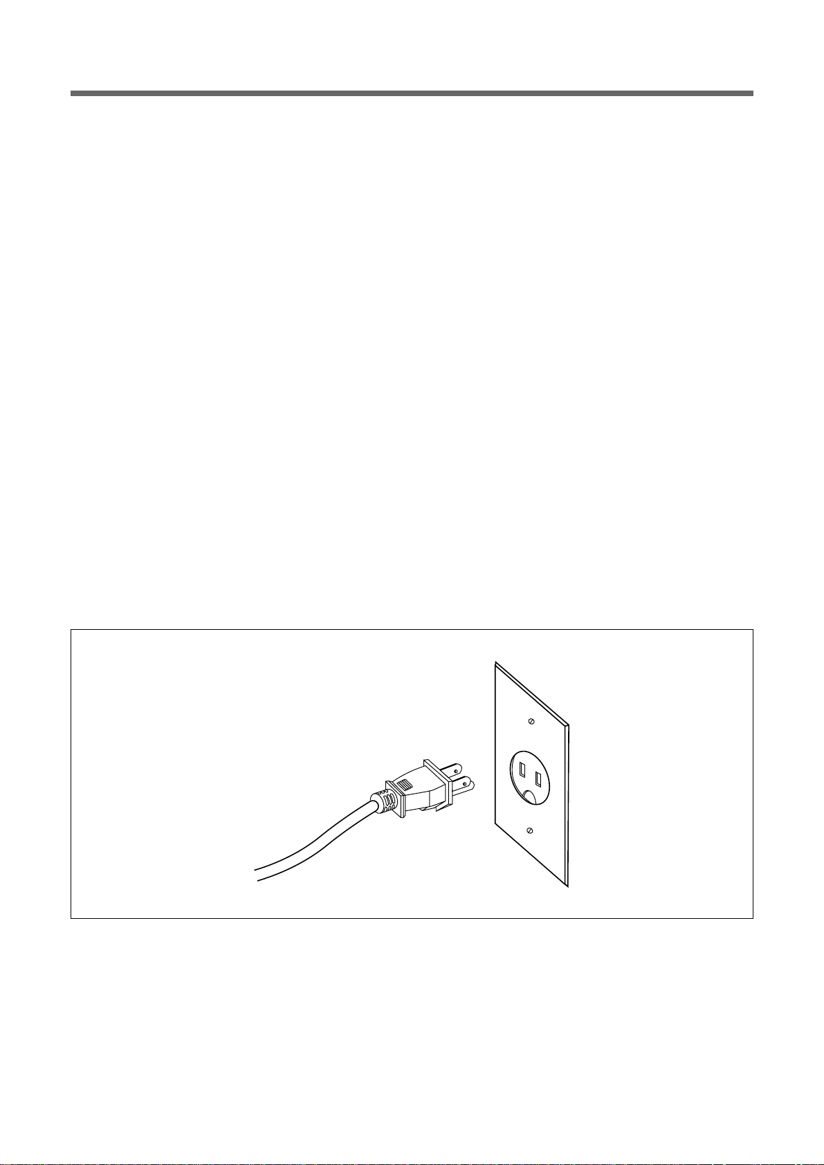
5.Power supply
• Check your local power source.
This microwave oven requires a current of approximately 12/10(KOR-630A9A) amperes, 120Volts, 60Hz
grounded outlet.
• Power supply cord is about 0.8 meters long.
1. A short power-supply cord is provided to reduce the risks resulting from becoming entangled in or tripping over
a longer cord.
2. Longer cord sets or extension cords are available and may be used if care is exercised in their use.
3. If a long cord or extension cord is used:
1) The marked electrical rating of the cord set or extension cord should be at least as great as the electrical rating of the appliance.
2) The extension cord must be a grounding type 3-wire cord.
3) The longer cord should be arranged so that it will not drape over the counter top or tabletop where it can be
pulled on by children or tripped over unintentionally.
6. Examine the oven after unpacking for any damage such as:
A misaligned door, broken door or a dent in cavity.
If any of the above are visible, DO NOT INSTALL, and notify dealer immediately.
6
OPERATIONS AND FUNCTIONS
11.Connect the main lead to an electrical outlet.
12. After placing the food in a suitable container, open the oven
door and put it on the glass tray. The glass tray must always
be in place during cooking.
13. Close the door securely.
14. Choose cooking power level by setting V.P.C knob to the
desired position. Refer to cookbook for recommended power
levels.
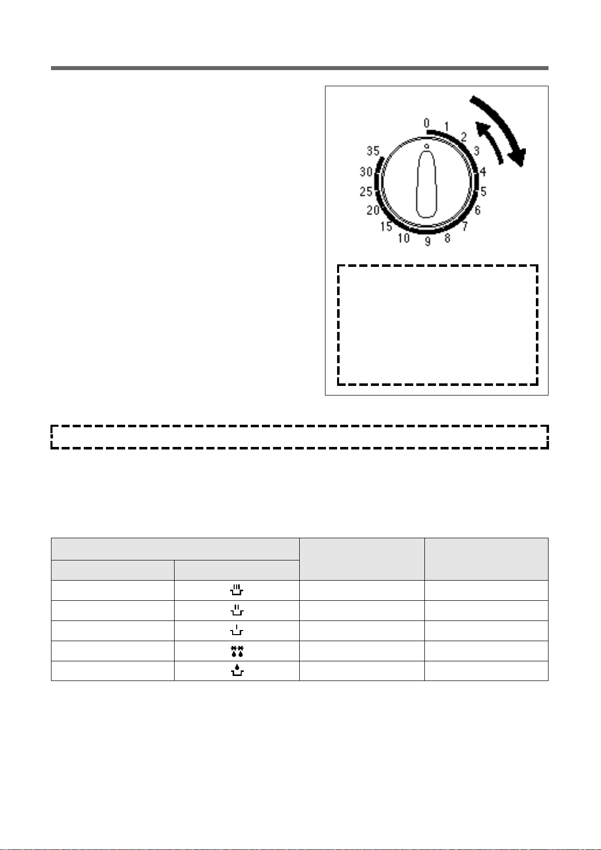
15. Determine cooking time.
Consult cookbook for recipe timing.
Oven light turns on and cooling fan starts to operate.
Microwave cooking starts.
16. You may open the door while the oven is operating.
As soon as the door is opened, the safety mechanism stop
the generation of microwave power and the operation of cooking timer
If you wish to change the time during cooking, simply adjust
the timer to the desired time.
17. When the timer reaches zero, a bell will ring and the unit will
turn off.
Oven light turns off. If additional cooking time is needed and
the door is closed, the oven will autom atically start when the
timer is reset.
Variable power cooking
• On and OFF cycle time of mechanical V.P.C switch is 30 seconds.
When the V.P.C knob is set to the desired position and timer knob turns to the desired position, the V.P.C switch has
a cycle (ON/OFF time(sec.)) listed below.
Make sure the oven is properly installed and plugged into the belectrical outlet.
Variable power setting
Approximate Percentage
Power level Symbol
ON/OFF time (sec.)
of Power
REHEAT 30/0 100%
ROAST 23.2/6.8 77%
MEDIUM 78.5/13.5 55%
DEFROST 9.8/20.2 33%
LOW 5/25 17%
NOTE
1. When setting timer for less than 2 minutes, turn the timer past 2 minutes and
then return to the correct timer setting
2.Various clicking noises may be heard
when turning V.P.C knob. This is normal
and does not affect the operation of your
microwave oven.
 Loading...