

Page 1

Service Manual
Microwave Oven
Model: KOR-618M/Q2S
KOR-619M/Q2S
DAEWOO ELECTRONICS CO., LTD.
Page 2

1
PRECAUTIONS TO BE OBSERVED BEFORE AND
DURING SERVICING T O AVOID POSSIBLE
EXPOSURE TO EXCESSIVE MICROWAVE ENERGY
(a) Do not operate or allow the oven to be operated with door open.
(b) Make the following safety checks on all ovens to be serviced before activating the magnetron or other
microwave source, and make repairs as necessary : (1) Interlock operation, (2) proper door closing, (3)
seal and sealing surfaces (arcing, wear, and other damage), (4) damage to or loosening of hinges and
latches (5) evidence of dropping or abuse.
(c) Before turning on microwave power for any service test or inspection within the microwave gernerating
compartments, check the magnetron, wave guide or transmission line, and cavity for proper alignment,
intergrity, and connections.
(d) Any defective or misadjusted components in the interlock, monitor, door seal, and microwave gernera-
tion and transmission systems shall be repaired, or adjusted by procedures described in this manual
before the oven is released to the owner.
(e) A micrewave leakage check to verify compliance with the Federal Performance Standard should be per-
formed on each oven prior to release to the owner.
PROPER USE AND SERVICE PRECAUTIONS..................................................................................................... 2
SPECIFICATIONS.................................................................................................................................................... 3
FEATURES DIAGRAM ............................................................................................................................................ 4
EARTHING INSTRUCTIONS................................................................................................................................... 5
INSTALLATION........................................................................................................................................................ 5
OPERATION PROCEDURE............................................................................................................ ........................ 6
CONTROLS.............................................................................................................................................................. 7
INTERLOCK MECHANISM FUNCTIONS AND ADJUSTMENTS..........................................................................22
MEASUREMENT OF THE MICROWAVE OUTPUT POWER................................................................................24
MICROWAVE RADIATION TEST............................................................................................................................ 25
WIRING DIAGRAM .................................................................................................................................................. 26
CIRCUIT DESCRIPTION.........................................................................................................................................28
SAFETY PRECAUTIONS FOR DISASSEMBLY AND REPAIR............................................................................. 31
DISASSEMBLY AND ASSEMBLY...........................................................................................................................32
TROUBLE SHOOTING GUIDE................................................................................................................................37
COMPONENT TEST PROCEDURE .......................................................................................................................46
SAFETY INTERLOCK CONTINUITY TEST............................................................................................................ 47
PRINTED CIRCUIT BOARD....................................................................................................................................48
CIRCUIT CHECK PROCEDURE.........................................................................................................................48
P.C.B. CIRCUIT DIAGRAM..................................................................................................................................53
COMPONENT INFORMATION............................................................................................................................55
PRINTED CIRCUITS BOARD.............................................................................................................................. 56
P.C.B. LOCATION NO .........................................................................................................................................57
EXPLODED AND PARTS LIST ...............................................................................................................................58
T ABLE OF CONTENTS
Page 3

1. FOR SAFE OPERATION
Damage that allows the microwave energy (that cooks or heats the food) to escape will result in poor cooking
and may cause serious bodily injury tok the operator.
IF ANY OF THE FOLLOWING CONDITIONS EXIST. OPERATOR MUST NOT USE THE APPLIANCE. (Only a
trained service personnel should make repairs.)
1) A broken door hinge.
2) A broken door viewing screen.
3) A broken front panel, oven cavity.
4) A loosened door lock.
5) A broken door lock.
The door gasket plate and oven cavity surface should be kept clean.
No grease, soil or spatter should be allowed to build up on these surfaces or inside the oven.
DO NOT ATTEMPT TO OPERATE THIS APPLIANCE WITH THE DOOR OPEN. The microwave Oven has
concealed switches to make sure the power is turned off when the door is opened. Do not attempt to defeat
them.
DO NOT ATTEMPT TO SERVICE THIS APPLIANCE UNTIL YOU HAVE READ THIS SERVICE MANUAL.
2. FOR SAFE SERVICE PROCEDURES
1) If the oven is operative prior to servicing, a microwave emission check should be performed prior to servicing
the oven.
2) If any certified oven unit is found to have excessive emission level 5mW/cm2, the service person should:
(a) inform the manufacturer, importer or assembler,
(b) repair the unit at no cost to the owner,
(c) attempt to ascertain the cause of the excessive leakage,
(d) tell the owner of the unit not to use the unit until the oven has been brought into compliance.
3) If the oven operates with the door open, the service person should tell the user not to operate the oven and
contact the manufacturer and CDRH immediately.
PROPER USE AND SERVICE PRECAUTIONS
2
CAUTION : This Device is to be Serviced Only by Properly Qualified Service Personnel. Consult the
Service Manual for Proper Service Procedures to Assure Continued Safety Operation and for
Precautions to be Taken to Avoid Possible Exposure to Excessive Microwave Energy.
Page 4
* Specifications are subject to change without notice.
ITEM
POWER SUPPLY
POWER CONSUMPTION
MICROWAVE
OUTPUT POWER
FREQUENCY
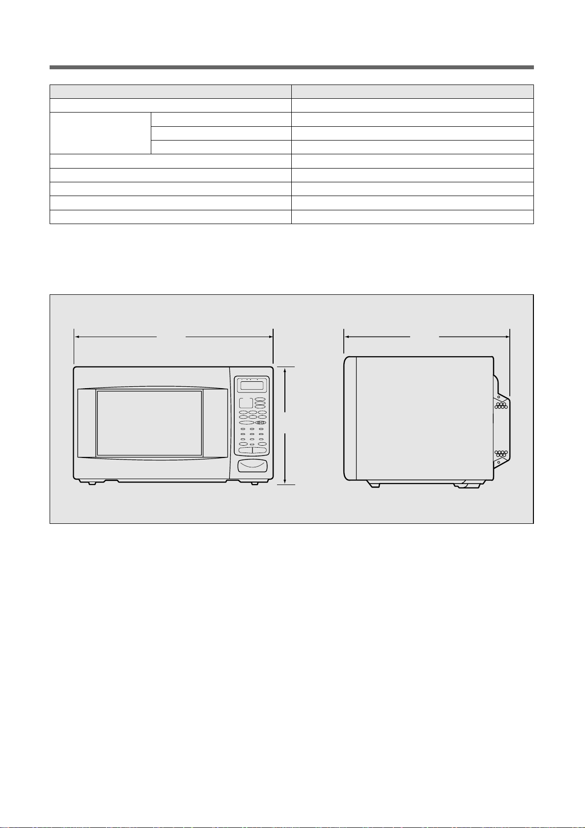
OUTSIDE DIMENSIONS (W x H x D)
CAVITY DIMENSIONS (W x H x D)
NET WEIGHT
TIMER
MICROWAVE POWER LEVELS
SPECIFICATION
230V~50Hz, SINGLE PHASE WITH EARTHING
1200 W
800 W (IEC 705)
2450 MHz
465 x 274 x 352 mm
290 x 200 x 290 mm
APPROX. 13.5kg
59 min. 99 sec.
10 – LEVELS
3
SPECIFICA TIONS
WEIGHT TIME START
DEFROSTSTAGE AUTO
LOCK NO CUP g
Auto Cook
1. Raked Potato
2, Fresh Vegetable
3. Soup
4. Fish Fillets
5. Meat Loaf
Menu
Weight
Auto Def.
Beverage
popcorn
Muffin
Frozen
Pizza
Dinner
Plate
PowerClock / A.Start
Speedy Cook
Feeding
Bottle
1 2 3
4 5 6
7 8 9
0
Stop/Clear Start
1 2
352465
274
Page 5
4
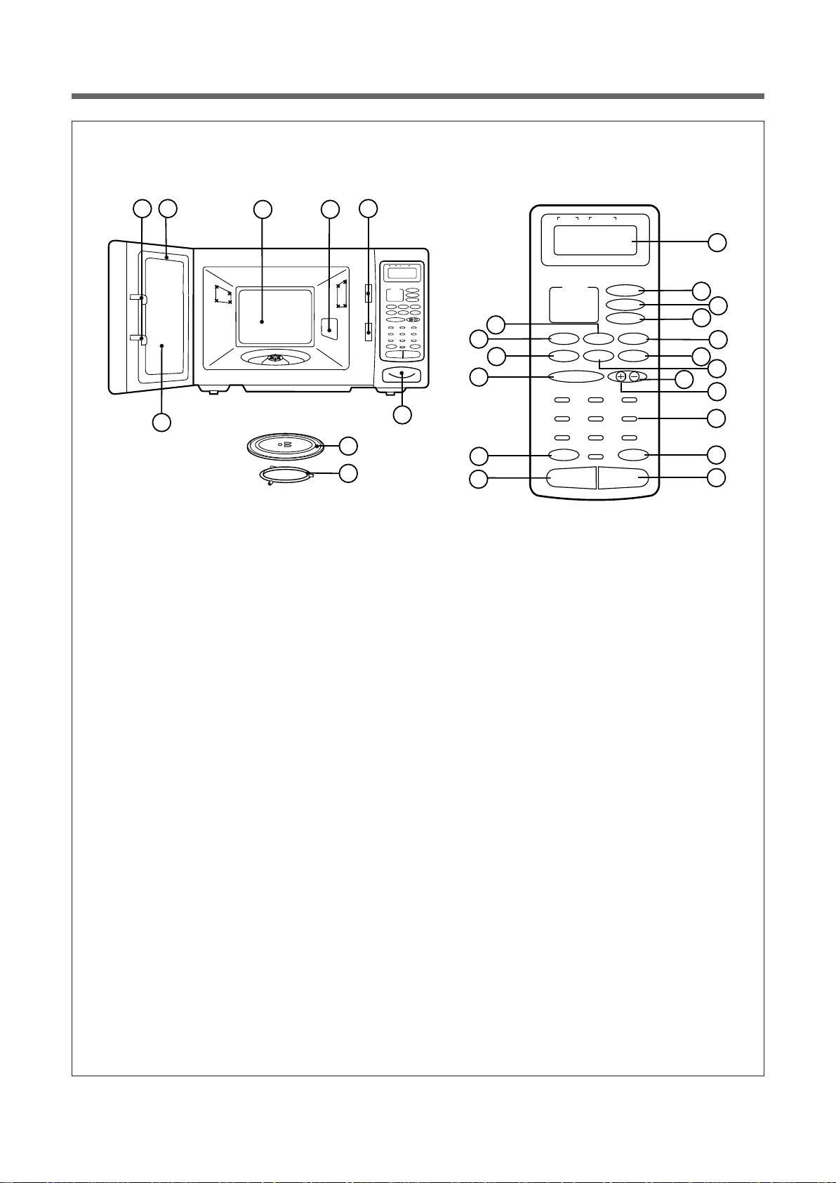
FEA TURES DIAGRAM : M-TYPE
1 Door latch–When the door is closed it will
automatically shut off. If the door is opened
while the oven is operating. The magnetron will
automatically shut off.
2 Door seal–The door seal maintains the
microwave within the oven cavity and prevents
microwave leakage.
3 Oven cavity.
4 Spatter shield–Protects the microwave outlet
from splashes of cooking foods.
5 Safety interlock system–Prevents the oven
from operating while the door is opened.
6 Door release button–Pushing this button
stops oven operation and opens the door.
7 Glass cooking tray–Made of special heat
resistant glass. The tray must always be in
proper position before operating. Do not cook
food directly on the tray.
8 Roller guide–Supports the glass cooking tray.
9 Door screen–Allows the glass cooked tray.
0 Time set pad–Used to set the cooking time
and the present time
q Display–Cooking time, power level, present
time are displayed.
w Menu–Uesd to select foods.
e Weight–Uesd to select quantity of foods.
r Speedy cook–Touch to set the any desired
reheat setting.
t Popcorn–Used to cook popcorn.
y Muffin–Used to cook muffin.
u Dinner plate–Used to reheat dinner plate.
i Beverage–Used to reheat beverage.
o Frozen pizza–Used to reheat frozen pizza.
p More–Used to add on one touch cooking.
a Less–Used to add on one touch cooking.
s Auto defrost–Used to defrost foods.
d Power–Used to set power level.
f Clock/A.start–Used to set clock & Used to set
auto start.
g Stop/Clear–User to stop the oven operation or
to delete the cooking data.
h Start–Used to start a selected operation.
j Feeding bottle–Used to sterilize bottle.
1
2
3
5
4
1 2
DEFROSTSTAGE AUTO
WEIGHT TIME START
11
DEFROSTSTAGE AUTO
1 2
WEIGHT TIME START
LOCK NO CUP g
Auto Cook
Menu
1. Raked Potato
2, Fresh Vegetable
3. Soup
Weight
4. Fish Fillets
5. Meat Loaf
Auto Def.
Frozen
Dinner
popcorn
Pizza
Plate
Feeding
Beverage
Muffin
Bottle
Speedy Cook
1 2 3
4 5 6
7 8 9
0
Stop/Clear Start
PowerClock / A.Start
19
17
16
14
9
7
8
6
24
25
LOCK NO CUP g
Auto Cook
1. Raked Potato
2, Fresh Vegetable
3. Soup
4. Fish Fillets
5. Meat Loaf
Dinner
Plate
Muffin
Speedy Cook
Frozen
Pizza
Beverage
Menu
Weight
Auto Def.
1 2 3
4 5 6
7 8 9
0
Stop/Clear Start
popcorn
Feeding
Bottle
PowerClock / A.Start
21
12
13
22
15
27
18
20
10
23
26
Page 6
4-1
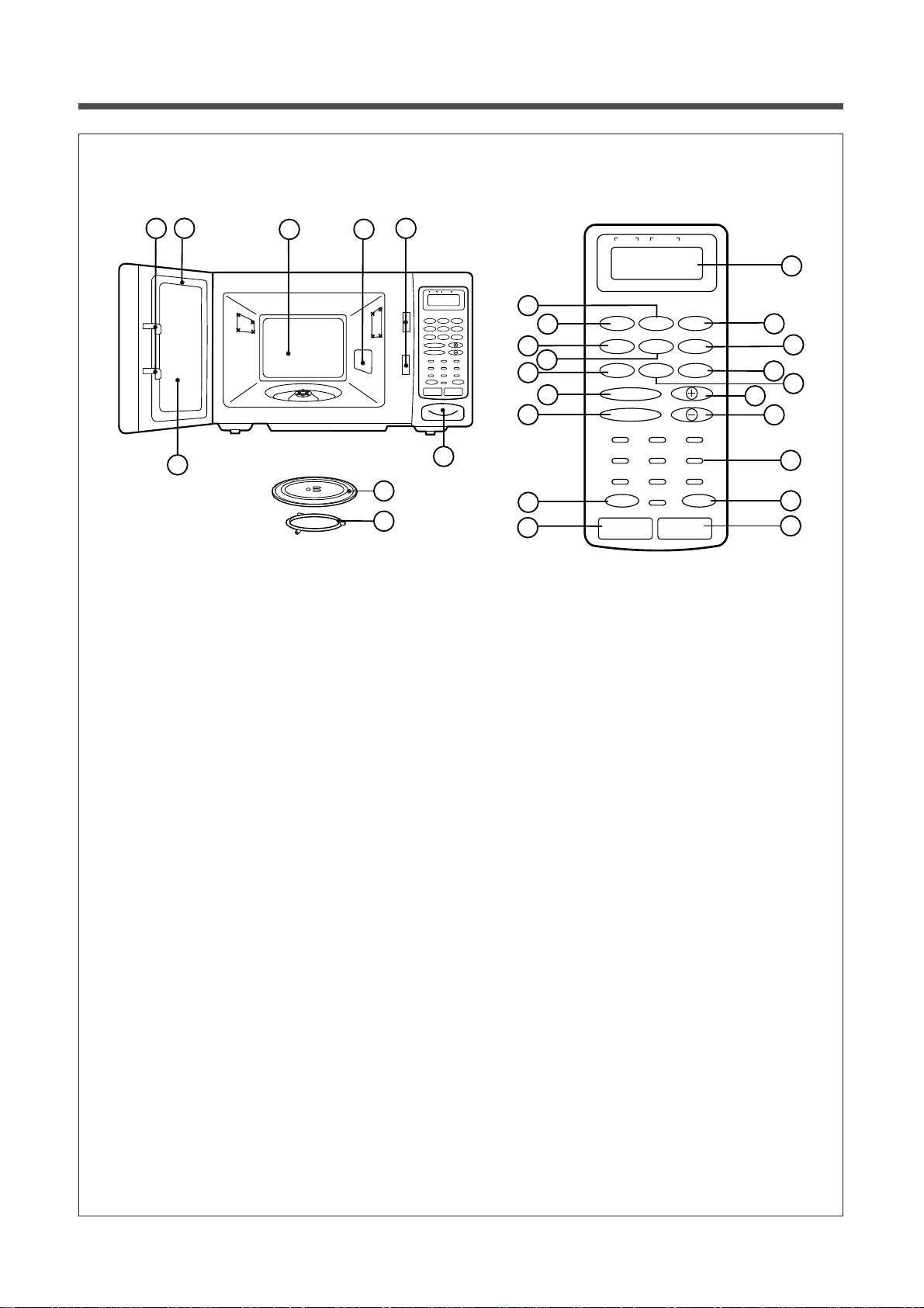
FEA TURES DIAGRAM : Q-TYPE
1 Door latch–When the door is closed it will
automatically shut off. If the door is opened
while the oven is operating. The magnetron will
automatically shut off.
2 Door seal–The door seal maintains the
microwave within the oven cavity and prevents
microwave leakage.
3 Oven cavity.
4 Spatter shield–Protects the microwave outlet
from splashes of cooking foods.
5 Safety interlock system–Prevents the oven
from operating while the door is opened.
6 Door release button–Pushing this button
stops oven operation and opens the door.
7 Glass cooking tray–Made of special heat
resistant glass. The tray must always be in
proper position before operating. Do not cook
food directly on the tray.
8 Roller guide–Supports the glass cooking tray.
9 Door screen–Allows viewing of food. The
screen is designed so that light can pass
through, but not the microwaves.
0 Time set pad–Used to set the cooking time
and the present time
q Display–Cooking time, power level, present
time are displayed.
w Speedy cook–Touch to set the any desired
reheat setting.
e Popcorn–Uesd to cook popcorn.
r Muffin–Used to cook muffin.
t Baked potato–Used to baked potato.
y Dinner plate–Used to reheat dinner plate.
u Soup–Used to reheat soup.
i Beverage–Used to reheat beverage.
o Frozen pizza–Used to reheat frozen pizza.
p Fresh vegetable–Used to blanch fresh veg-
etable.
a More–Used to add on one touch cooking.
s Less–Used to remove one touch cooking.
d Auto defrost–Used to defrost foods.
f Power–Used to set power level.
g Clock/A.start–Used to set clock & Used to set
auto start.
y Feeding bottle–Used to sterilize bottle.
u Stop/Clear–Used to stop the oven operation or
to delete the cooking data.
i Start–Used to start a selected operation.
1
2
3
5
4
1 2
DEFROSTSTAGE AUTO
WEIGHT TIME START
11
DEFROSTSTAGE AUTO
1 2
WEIGHT TIME START
LOCK NO CUP g
Beverage
Soup Muffin
Baked
Frozen
Potato
Pizza
Fresh
Beverage
Vegetable
Speedy Cook
Auto Def.
1 2 3
4 5 6
7 8 9
0
Stop/Clear Start
17
15
20
13
19
Dinner
Plate
Feeding
Bottle
PowerClock / A.Start
12
23
LOCK NO CUP g
Popcorn
Soup Muffin
Baked
Frozen
Potato
Pizza
Fresh
Beverage
Vegetable
Speedy Cook
Auto Def.
Dinner
Plate
Feeding
Bottle
21
14
16
26
18
22
1 2 3
9
7
8
6
24
27
4 5 6
7 8 9
0
Clock / A.Start
Power
Stop/Clear Start
10
25
28
Page 7

5
This appliance must be earthed. In the event of an electrical short circuit, earthing reduces the risk of electric
shock by providing an escape, wire for the electric current. This appliance is equipped with a cord having a earthing wire with a earthing plug. The ploug must be plugged into an outlet that is properly installed and earthed.
EARTHING INSTRUCTIONS
INST ALLATION
WARNING : Improper use of the earthing plug can result in a risk of electric shock. consult a qualified electri-
cian or serviceman if the earthing instructions are not completely understood, or if doubt extension to whether the appliance is properly earthed. If it necessary to use an extension cord, use
only a 3-wire extension cord that has a 3-blade earthing plug, and a 3-slot receptacle that will
accept the plug on the appliance. The marked rating of the extension cord should be equal to or
greater than the electrical rating of the appliance.
Steady, flat location
This oven should be set on a steady, flat surface.
This oven is designed for counter top use only.
Leave space behind and side
All air vents should be kept a clearance. lf all vents are covered during operation, the oven may overheat
and, eventually, oven failure.
Away from Radio and TV sets
Poor television reception and radio interference may result if the oven is located close to a TV, Radio, or
antenna, feeder and so on.
Position the oven as far from them as possible.
Away from heating appliances and water taps
Keep the oven away from hot air, steam or splash when choosing a place to position it, or the insulation
might be adversely affected and breakdowns occur.
Power supply
• Check uour local power source. This oven requires a current of approximately 6 amperes. 230V 50Hz.
• Power supply cord is about 1.0 meters long.
• The voltage used must be the same as specified on this oven. Using a higher voltage may result in a fire or
other accident causing oven damage. Using low voltage will cause slow cooking. We are not responsible
for damage resulting from use of this oven with a voltage of ampere fuse other than those specified.
• This appliance is supplied with cable of special type, which, if damaged, must be repaired with cable of
same type. such a cable can be purchased from DAEWOO and must be installed by a Qualified Person.
Examine the oven after unpacking for any damage such as:
QA misaligned door, broken door, A dent in cavity.
If any of the above are visible, DO NOT INSTALL, and notify dealer immediately.
Do not operate the oven if it is colder than room termperature.
(This may occur during delivery in cold weather.) Allow the oven to become room temperature before operating.
1
2
3
4
5
6
7
Page 8

6
Touch Power pad,
Once the touch
POWER
9
8
7
6
5
4
3
2
1
0
Power Level (Display)
P-HI
P-90
P-80
P-70
P-60
P-50
P-40
P-30
P-20
P-10
P-00
Approximate Percentage
of Power
100%
90%
80%
70%
60%
50%
40%
30%
20%
10%
0%
This section includes useful information about oven operation.
1. Plug power supply cord into a 230V 50Hz power outlet.
2. After placing the food in a suitable container, open the oven door and put it on the glass tray.
The glass tray must always be in place during cooking.
3. Shut the door. Make sure that it is firmly closed.
WATTAGE OUTPUT CHART
The power-level is set by pressing the POWER pad. The chart shows the display, the power level and the percentage of power.
OPERA TION PROCEDURE
When the oven door is opened, the light turns
off.
The oven door can be opened at any time during operation by touching the door release button on the control panel. The oven will automatically shut off. To restart the oven. close the door
and then touch START.
Each time a pad is touched, a BEEP will sound
to acknowledge the touch.
The oven automatically cook on full power
unless set to a lower opwer level.
The display will show “ : 0” when the oven is
plugged in.
Time clock returns tol the present time when the
cooking time ends.
When the STOP/CLEAR pad is touched during the
oven operation, the oven stops cooking and all
information retained. To erase all information
retained. To erase all information (except the present time), touch the STOP/CLEAR pad once
more. lf the oven door is opened during the oven
operation, all information is retained.
If the START pad is touched and the oven does
not operate, check the area between the door and
door is closed securely. The oven will not start
cooking until the door is completely closed or the
program has been reset.
1
2
3
4
5
6
7
8
Make sure the oven is properly installed and
plugged into the electrical outlet.
Page 9
7
When the oven is first plugged in, the display will flash “ : 0” and a tone will sound. If the AC power ever goes off,
the display will flash “ : 0” when the power comes back on.
DO THIS THIS HAPPENS...
CONTROLS
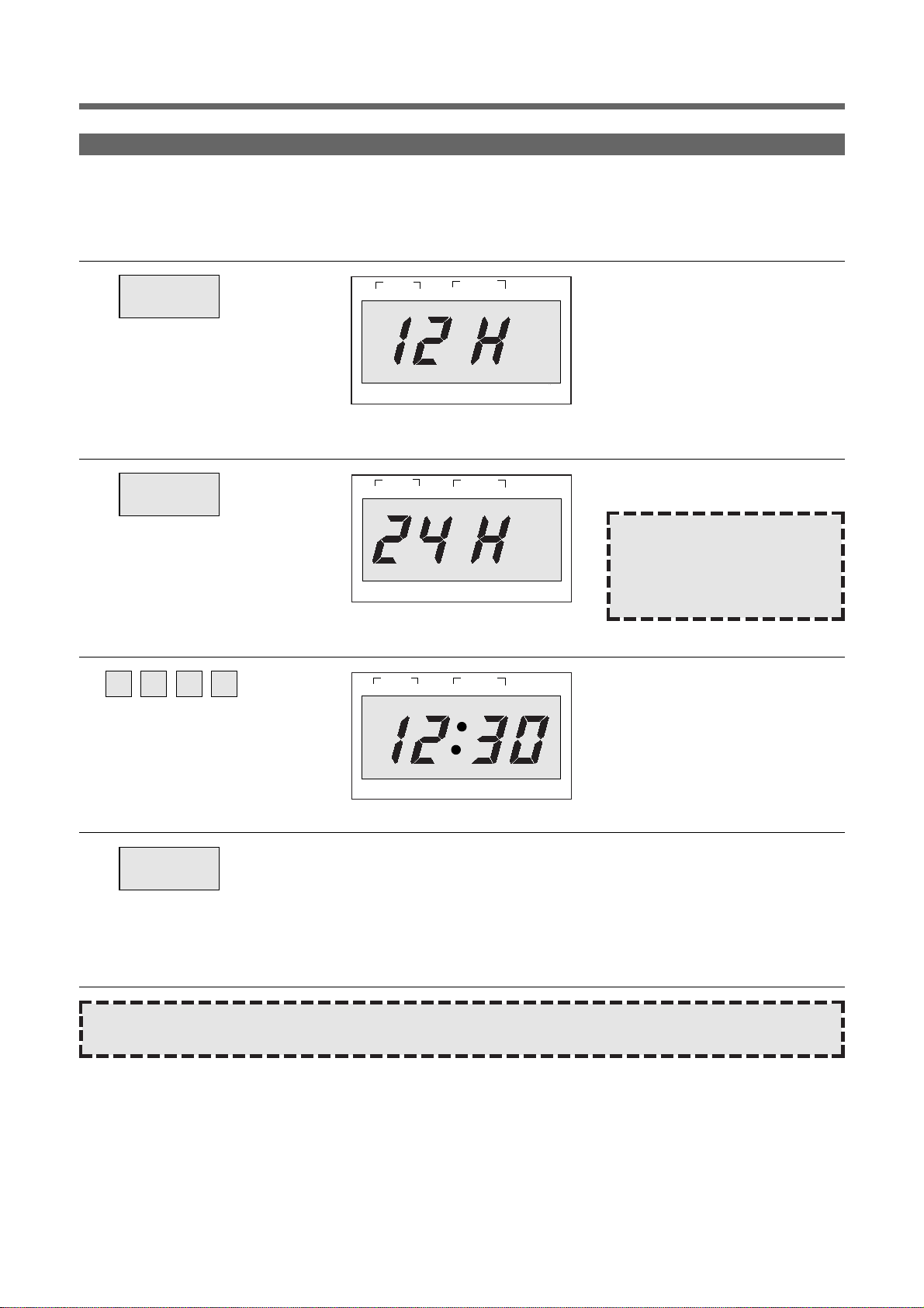
SETTING THE CLOCK
1. Touch CLOCK / A.START pad.
This is a 12 hour clock system.
CLOCK/
A.START
2. Touch CLOCK/A.START pad
once more.
This is a 24 hour clock system.
CLOCK/
A.START
4. Touch CLOCK/A.START pad.
The display stop blinking and the colon starts blinking.
If you selected 12 hour clock system this digital clock allows you to set
from 1:00 to 12:59.
If you selected 24 hour clock system, this digital clock allows you to set
from 0:00 to 23:59
CLOCK/
A.START
3. Enter the correct time of day by
touching the numbers in
sequence.
The display will then begin blinking.
1 2 3 0
NOTE : This oven is multiple
clock system. If you
want 12 hour clock
system, can be omitted this step.
NOTE : If you attempt to enter an incorrect time, the time will not be set and a error signal tone will sound.
Touch the CLOCK/A.START pad re-enter the time.
g
g
gg
STAGE AUTO
1
LOCK NO CUPS
STAGE
1
LOCK
1
NO CUPS
STAGE
2
WEIGHT TIME
2
WEIGHT TIME
WEIGHT TIME
2
DEFROST
DEFROST AUTO
DEFROST AUTO
START
oz lb
START
oz lb
START
LOCK
NO CUPS
oz lb
Page 10
8
WEIGHT DEFROST lets you easily defrost food by eliminating guesswork in determining defrosting time. The minimum weight for WEIGHT DEFROST is 200 grams. The maximum weight for WEIGHT DEFROST is 3000 grams.
Follow the steps below for easy defrosting.
WEIGHT DEFROSTING
DO THIS THIS HAPPENS...
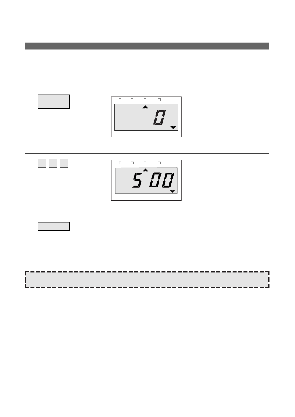
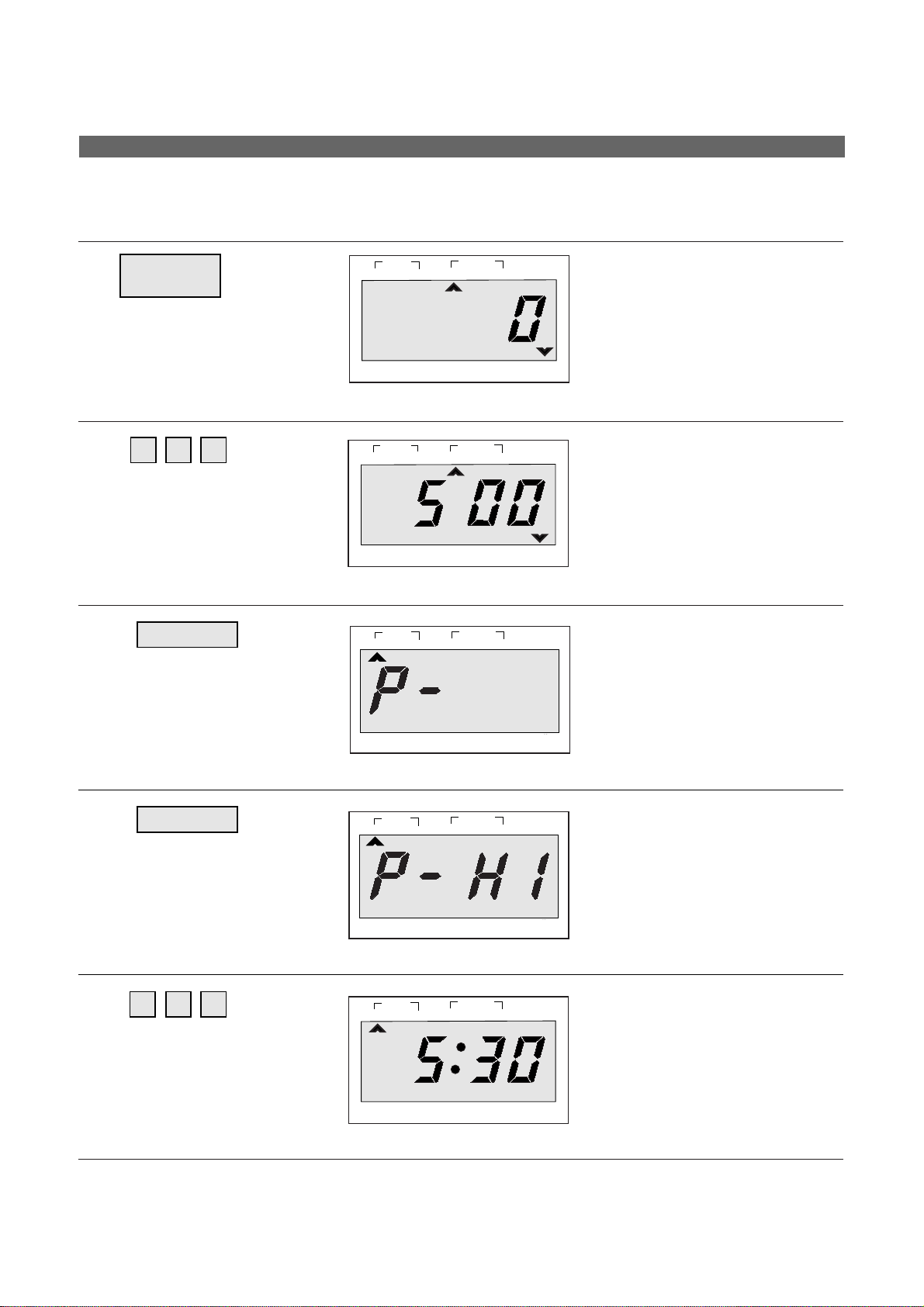
1. Touch AUTO DEFROST pad.
The WEIGHT DEFROST indicator
lights and “0” is displayed. And the
g indicator starts blinking.
AUTO
DEFROST
2. Touch number pads for the
defrosting weight
you want.
The display will show the numbers
you pressed in the order you
touched.
5 0 0
3. Touch START pad.
WEIGHT DEFROSTING begins. The defrosting time is automatically
determined by the food category and weight entered.
The g indicator goes off and the WEIGHT DEFROST indicator blinks and
the defrosting time counts down in the display window. The oven beeps
during the defrosting cycle to signal that the food needs to be turned or
rearranged.
When the defrosting time ends, you will hear 3 beeps.
START
NOTE : To prevent over defrosting thin areas or edges can be shielded with strips of aluminum foil.
1
STAGE
LOCK
1
STAGE
LOCK
WEIGHT TIME
2
NO CUPS
WEIGHT TIME
2
NO CUPS
DEFROST AUTO
DEFROST AUTO
START
g
START
g
Page 11
9
When TIME DEFROST is selected, the automatic cycle divides the defrosting time into periods of alternating
defrost and stand times by cycling on and off.
TIME DEFROSTING
DO THIS THIS HAPPENS...
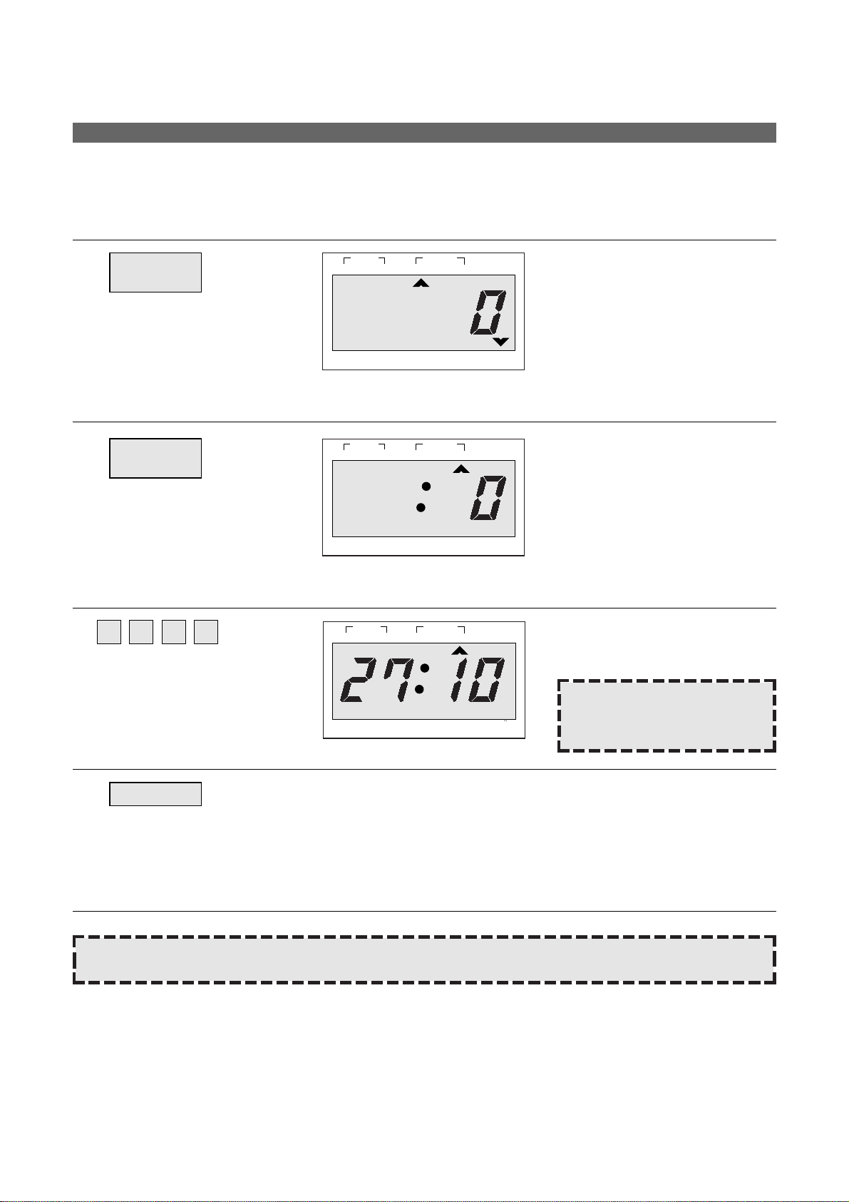
1. Touch AUTO DEFROST pad.
The WEIGHT DEFROST indicator
lights and “0” is displayed. And the
g indicator starts blinking.
AUTO
DEFROST
2. Touch AUTO DEFROST pad
once more.
The TIME DEFROST indicator
lights and “ : 0” is displayed.
AUTO
DEFROST
3. Touch number pads for the
defrosting time you want.
The display will show the numbers
you pressed in the order you
touched.
2 7 1 0
NOTE : Your oven can be
programmed for 59 minutes
99 seconds. (59:99)
4. Touch START pad.
When you touch START pad, the TIME DEFROST indicator starts blinking to show the oven is in the TIME DEFROST mode. The display counts
down the time to show you how much defrosting time is left in the TIME
DEFROST mode. The oven beeps during the defrosting cycle to signal
that the food needs to be turned or rearranged. When the defrosting time
ends, you will hear 3 beeps.
START
NOTE : To prevent over defrosting, thin areas or edges can be shielded with strips of aluminum foil.
g
g
g
1
STAGE
LOCK
1
STAGE
LOCK
1
STAGE
LOCK NO CUPS
WEIGHT TIME
2
NO CUPS
WEIGHT TIME
2
NO CUPS
2
WEIGHT TIME
DEFROST AUTO
DEFROST AUTO
DEFROST AUTO
START
oz lb
START
oz lb
START
oz lb
Page 12
10
DO THIS... THIS HAPPENS...
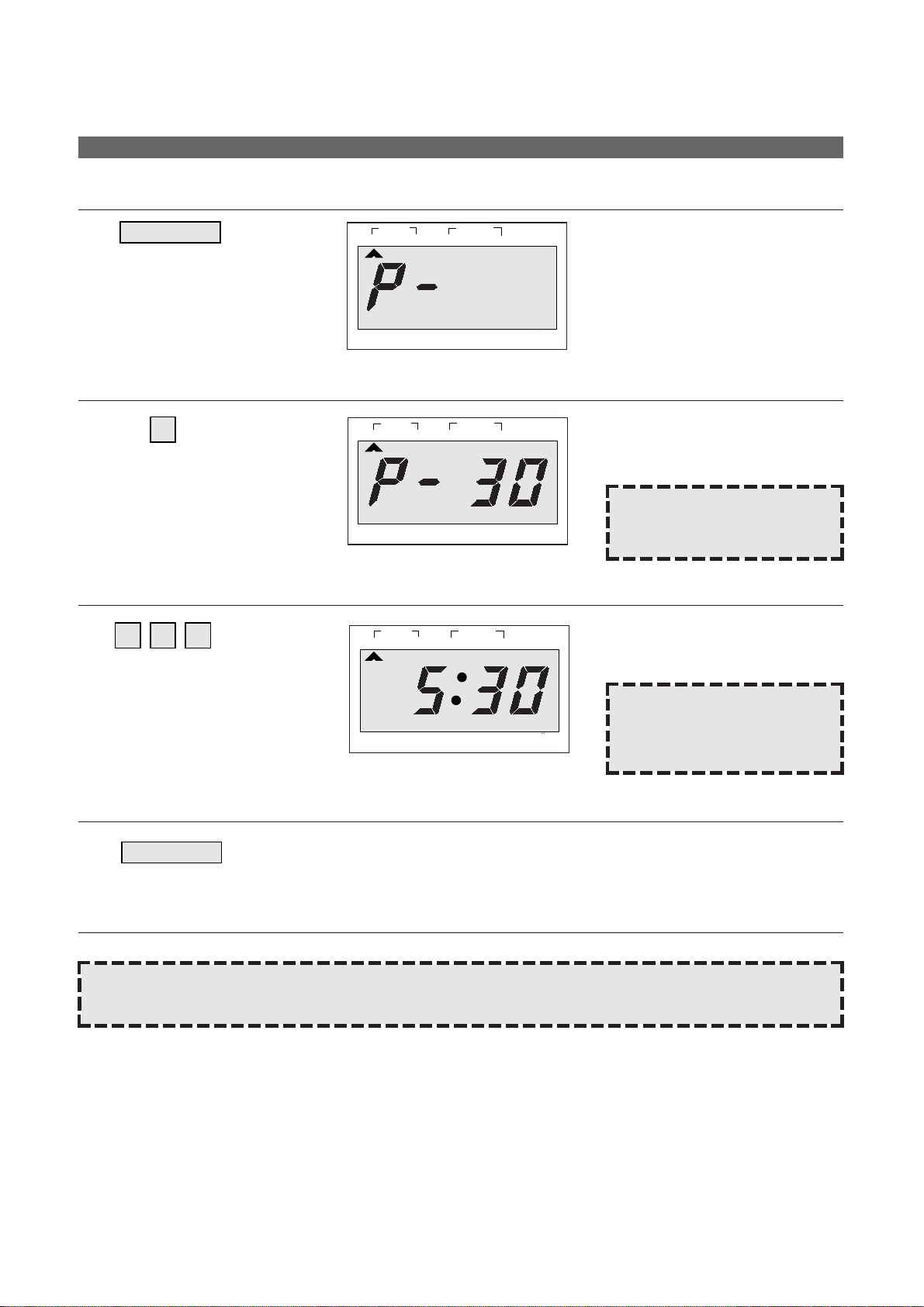
1. Touch POWER pad.
The STAGE1 indicator lights and
“P- ” is displayed.
POWER
4. Touch START pad.
When you touch START pad, the M/W indicator starts blinking to show
the oven is cooking.
The display counts down the time to show how much cooking time is left.
When the cooking time ends, you will hear 3 beeps.
START
2. Touch the number pad for the
power level you want.
The display will show what you
touched. This example shows
power level 3.
oz lb
STAGE
DEFROST AUTO
START
WEIGHT TIME
LOCK
1
2
NO CUPS
3
NOTE: If steps 1 and 2 are
omitted, the oven will
cook at full power.
3. Touch number pads for the
cooking time.
The display will show the numbers
you pressed in the order you
touched.
oz lb
STAGE
DEFROST AUTO
START
WEIGHT TIME
LOCK
1
2
NO CUPS
3 05
NOTE: Your oven can be pro-
grammed for 59 minutes 99 seconds.
(59:99)
NOTE: Using lower power levels increase the cooking time which is recommended for foods such as cheese,
milk and slow cooking of meats.
COOKING IN ONE ST AGE
g
g
g
1
STAGE
LOCK
2
WEIGHT TIME
NO CUPS
DEFROST AUTO
START
oz lb
Page 13
11
For best results, some recipes call for one Power Level for a certain length of time and another power level for a
different length of time.
Your microwave oven can be set to change from one to another.
DO THIS... THIS HAPPENS...
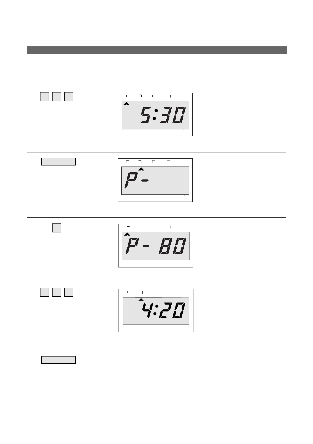
1. Touch number pads for the
cooking time you want in the
first stage.
The STAGE1 indicator lights and
the display will show the numbers
you pressed in the order you
touched.
This example shows 5 minutes 30
seconds at full power.
oz lb
STAGE
DEFROST AUTO
START
WEIGHT TIME
LOCK
1
2
NO CUPS
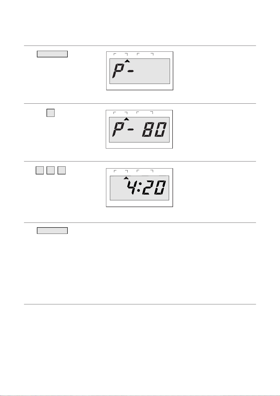
3. Touch the number pads for the
power level you want in the
second stage.
The display will show what you
touched.
4. Touch the number pads for the
cooking time you want in the
second stage.
The display will show the numbers
you pressed in the order you
touched.
This example shows 4 minutes 20
seconds at power level 8.
5. Touch START pad.
When you touch START pad, both STAGE1 & 2 indicator lights come on,
STAGE1 indicator light starts blinking to show you that the over is cooking
in the first of two cook stages. The oven will cook at the power you selected for stage one. At the end of stage one, the oven will beep and start
stage two, the STAGE1 indicator goes off and the STAGE2 indicator
starts blinking. The display counts down the time remaining in stage two
when stage two ends, you will hear 3 heeps.
START
POWER
2. Touch POWER pad.
The STAGE2 indicator lights and
“P-” is displayed.
DEFROST AUTO
START
WEIGHT TIME
LOCK
lb
oz
STAGE
1
2
NO CUPS
lb
oz
DEFROST AUTO
START
WEIGHT TIME
LOCK
STAGE
1
2
NO CUPS
lb
oz
DEFROST AUTO
START
WEIGHT TIME
LOCK
STAGE
1
2
NO CUPS
5 3 0
4 2 0
8
COOKING IN TWO ST AGES
g
g
g
g
Page 14
12
Some recipes require frozen foods to be thawed before cooking.
This oven can be programmed to automatically defrost foods before cooking.
DO THIS... THIS HAPPENS...
1. Touch AUTO DEFROST pad.
The WEIGHT DEFROST indicator
lights and “0” is displayed. And the
g indicator starts blinking.
AUTO
DEFROST
2. Touch number pads for the
defrosting weight you want.
The display will show the numbers
you pressed in the order you
touched.
g
STAGE
DEFROST AUTO
START
WEIGHT TIME
LOCK
1
2
NO CUPS
5 0 0
3. Touch POWER pad.
The STAGE1 indicator lights and
“P-” is displayed.
POWER
POWER
4. Touch POWER pad once more.
“P-HI” will appear in the displayed.
This example shows full power
(100%)
5. Touch number pads for the
cooking time you want in the
first stage.
The display will show the numbers
you pressed in the order you
touched. This example shows 5
minutes 30 seconds at full power.
35 0
WEIGHT DEFROSTING AND COOKING IN TWO ST AGES
g
g
g
g
g
1
STAGE
LOCK
STAGE
1
DEFROST AUTO
WEIGHT TIME
2
NO CUPS
2
WEIGHT TIME
START
lb
oz
DEFROST AUTO
START
LOCK
1
LOCK
1
LOCK
NO CUPS
STAGE
NO CUPS
STAGE
NO CUPS
DEFROST AUTO
WEIGHT TIME
2
DEFROST AUTO
WEIGHT TIME
2
lb
oz
START
lb
oz
START
lb
oz
Page 15
13
6. Touch POWER pad.
DEFROST AUTO
START
WEIGHT TIME
LOCK
lb
oz
STAGE
1
2
NO CUPS
lb
oz
DEFROST AUTO
START
WEIGHT TIME
LOCK
STAGE
1
2
NO CUPS
lb
oz
DEFROST AUTO
START
WEIGHT TIME
LOCK
STAGE
1
2
NO CUPS
DO THIS... THIS HAPPENS...
7. Touch the number pads for the
power level you want in the
second stage.
The display will show what you
touched.
8. Touch the number pads for the
cooking time you want in the
second stage.
The display will show the numbers
you pressed in the order you
touched.
This example shows 4 minutes 20
seconds at power level 8.
9. Touch START pad.
When you touch START pad, the WEIGHT DEFROST, STAGE1 and
STAGE2 indicators come on to confirm the power levels selected. The
WEIGHT DEFROST indicator starts blinking to show you that the oven is
in WEIGHT DEFROST mode. The display counts down the time remaining in WEIGHT DEFROST mode. Turn over, break a part and redistribute
at a beep.
At the end of WEIGHT DEFROST mode, the oven will beep and start
stage one. The WEIGHT DEFROST indicator goes off and the STAGE1
indicator starts blinking. The display counts down the time remaining in
stage one.
At the end of stage one, the oven will beep and start stage two. The
STAGE1 indicator goes off and the STAGE2 indicator starts blinking.
The display counts down the time remaining in stage two when stage two
ends, you will hear 3 beeps.
START
POWERPOWER
The STAGE2 indicator lights and
“P-” is displayed.
4 2 0
8
g
g
g
Page 16
14
Allows you to program cooking to start at a time you select.
The food will automatically start cooking at the desired time.
Program is able up to 2 stages (no acceptable DEFROST)
DO THIS... THIS HAPPENS...
1. Program the desired power level and cooking time.
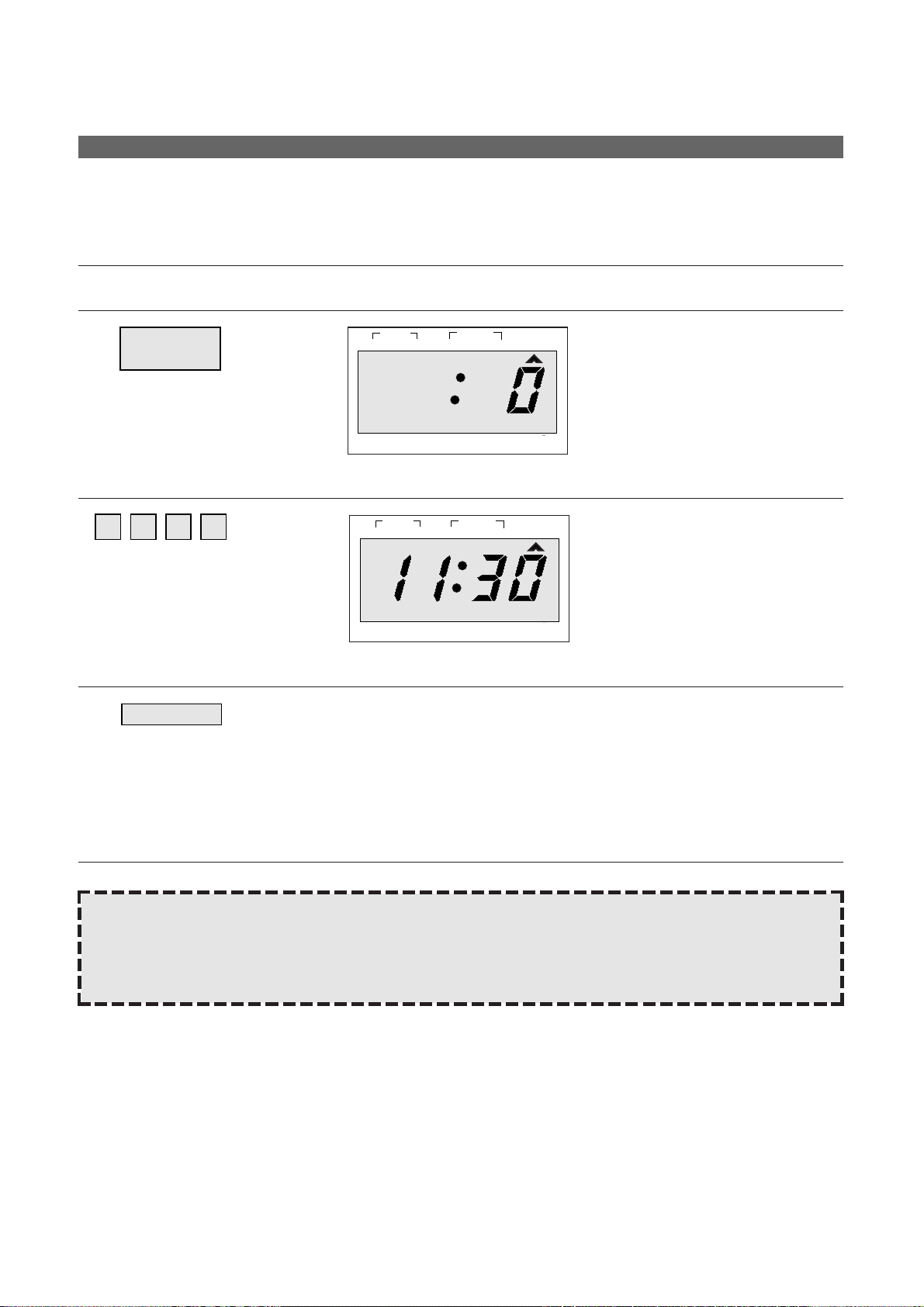
2. Touch CLOCK/A.START pad.
The AUTO START indicator lights
and “ :0” is displayed.
CLOCK/
A.START
4. Touch START pad.
When you touch START pad, the present time appears in the display and
the cooking program indicators come on.
The AUTO START indicator and the colon start blinking.
When the selected start time arrives the oven bigins. Operating and the
oven light turns on. The AUTO START indicator goes off and the next
stage indicator begins to blink.
When the cooking is completed you will hear 3 beeps. The oven turns off
and the present time appears in the display.
START
3. Enter the desired start time by
pressing the number pads.
The display will show the numbers
you pressed in the order you
touched.
This example shows 11:30
oz lb
STAGE
DEFROST AUTO
START
WEIGHT TIME
LOCK
1
2
NO CUPS
1 1 3 0
NOTE: AUTO START can be used for time cooking, if clock is set. If the oven door is opened after program-
ming AUTO START, it is necessary to touch the START pad for the time of day to appear in the readout so that the oven will automatically begin programmed cooking at the chosen AUTO START time.
Before setting, check to make sure the clock is showing the correct time of day.
AUTO ST ART
g
g
1
STAGE
LOCK
WEIGHT TIME
2
NO CUPS
DEFROST AUTO
START
oz lb
Page 17
15
Once you have correctly programmed the oven for AUTO START, the present time will appear on the display.
DO THIS... THIS HAPPENS...
SPEEDY COOK allows you to reheat for 30 seconds at 100% (full power) by simply touching the SPEEDY COOK
pad.
By repeatedly touching the SPEEDY COOK pad, you can also extend reheating time to 5 minutes by 30 seconds.
DO THIS... THIS HAPPENS...
1. Touch CLOCK/A.START pad.
The programmed AUTO START time will appear on the display for 3 seconds.
CLOCK/
A.START
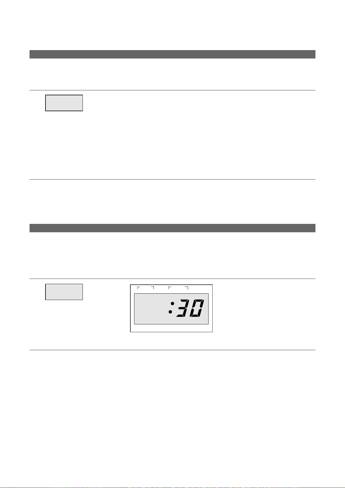
1. Touch SPEEDY COOK pad.
When you touch SPEEDY COOK,
“ :30” is displayed.
After 1.5 seconds, the oven starts
reheating.
SPEEDY
COOK
TO CHECK AUTO ST ART TIME
SPEEDY COOK
g
1
STAGE
LOCK
2
WEIGHT TIME
NO CUPS
DEFROST AUTO
START
oz lb
Page 18
16
One touch cook allows you to cook or reheat many of your favorite foods by touching just one pad. To increase
quantity, touch chosen pad until number in display is same as desired quantity to cook. (except for DINNER
PLATE)
DO THIS... THIS HAPPENS...
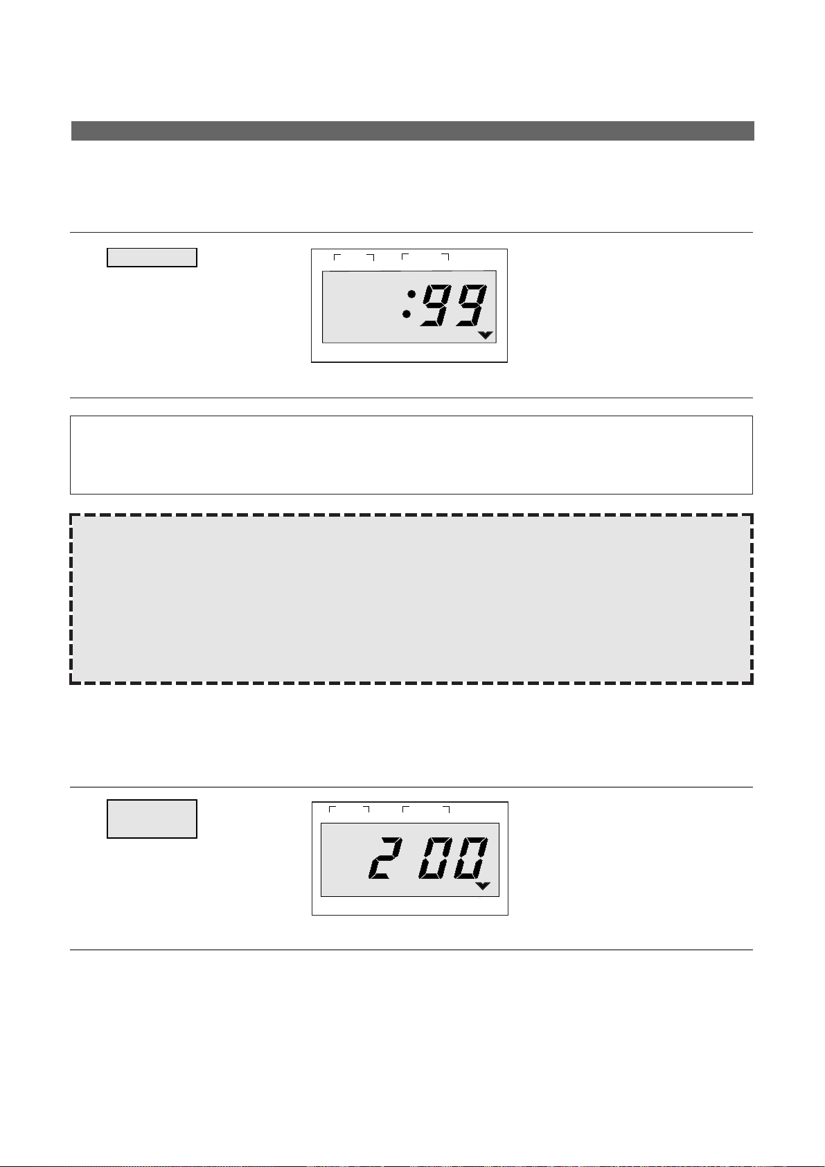
1. Touch POPCORN pad.
When you touch POPCORN pad,
“99” is displayed.
After 1.5 seconds, the display
changed into cooking time of quantity and the oven starts cooking.
POPCORN
1. Touch FROZEN PIZZA pad.
When you touch FROZEN PIZZA,
“200” is displayed.
After 1.5 seconds, the display
changed into cooking time of quantity and the oven starts cooking.
FROZEN
PIZZA
* POPCORN *
• 99g: Touch POPCORN once.
• 50g: Touch POPCORN twice within 1.5 seconds.
NOTE: 1. Use prespackaged room-temperature microwave popcorn.
2. Place bag in oven according to manufacturer’s directions.
3. Pop only one bag at a time.
4. After popping, open bag carefully, popcorn and steam are extremely hot.
5. Do not reheat unpopped kernels or reuse bag.
6. Do not leave oven unattended while popping popcorn.
CAUTION: If pre-packaged popcorn is of a different weight then the recommended weight, do not use the
popcorn setting, or inadequated popping or a fire may occur. Follow the manufacture’s instructions.
DO THIS... THIS HAPPENS...
ONE TOUCH COOKING
g
g
1
STAGE
DEFROST AUTO
WEIGHT TIME
2
LOCK
NO CUPS
START
lb
oz
1
STAGE
LOCK
2
NO CUPS
DEFROST AUTO
WEIGHT TIME
oz lb
START
Page 19
17
* FROZEN PIZZA *
• 200g: Touch FROZEN PIZZA once.
• 300g: Touch FROZEN PIZZA twice within 1.5 seconds.
NOTE: 1. Use only one frozen pizza at a time.
2. Use only frozen pizza for microwave oven.
3. If the cheese of frozen pizza does not melt sufficiently, cook a few seconds longer.
4. Some brands of frozen pizza may require more or less cooking time.
* BEVERAGE * (250ml/cup)
• 1 cups (mugs): Touch BEVERAGE once.
• 2 cups (mugs): Touch BEVERAGE twice within 1.5 seconds.
• 3 cups (mugs): Touch BEVERAGE three times within 1.5 seconds.
NOTE: 1. This setting is good for restoring cooled beverage to a better drinking temperature.
2. Stir after cooking.
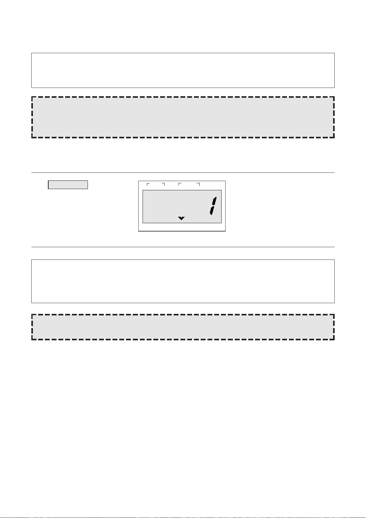
1. Touch BEVERAGE pad.
When you touch BEVERAGE pad,
“1” is displayed.
After 1.5 seconds, the display
changed into cooking time of quantity and the oven starts cooking.
BEVERAGE
DO THIS... THIS HAPPENS...
g
1
STAGE
LOCK
2
NO CUPS
DEFROST AUTO
WEIGHT TIME
oz lb
START
Page 20
18
DO THIS... THIS HAPPENS...
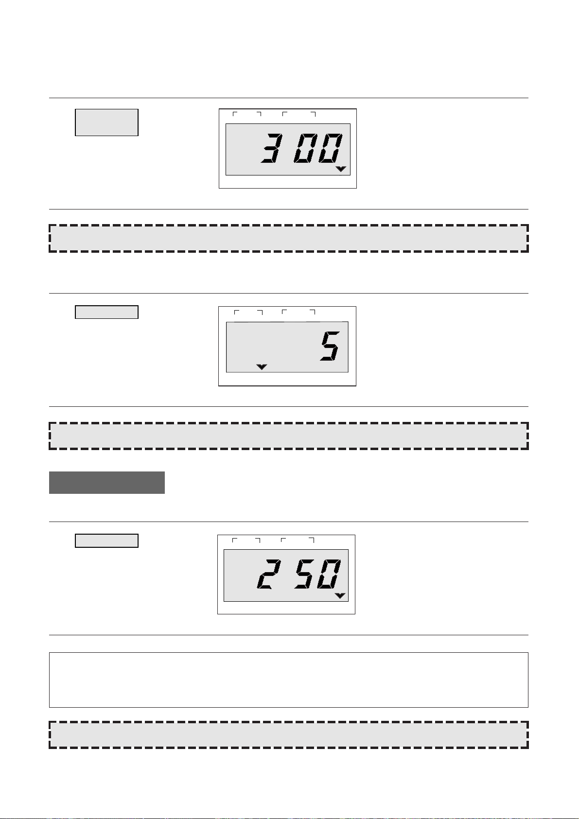
1. Touch DINNER PLATE pad.
When you touch DINNER PLATE
pad, “300“ is displayed.
After the 1.5 seconds, the display
changed into cooking time of quantity and the oven starts cooking.
DINNER
PLATE
NOTE: For best results, consult the cookbook.
NOTE: For best results, consult the cookbook.
1. Touch MUFFIN pad.
When you touch MUFFIN pad, “5”
is displayed.
After 1.5 seconds, the display
changed into cooking time of quantity and the oven starts cooking.
MUFFIN
DO THIS... THIS HAPPENS...
* SOUP *
• 250g: Touch SOUP once.
• 350g: Touch SOUP twice within 1.5 seconds.
NOTE: For best results, consult the cookbook.
1. Touch SOUP pad.
When you touch SOUP pad, “250”
is displayed.
After the 1.5 seconds, the display
changed into cooking time of quantity and the oven starts cooking.
SOUP
DO THIS... THIS HAPPENS...
Q-TYPE
g
g
1
STAGE
LOCK
2
WEIGHT TIME
NO CUPS
DEFROST AUTO
START
oz lb
1
STAGE
LOCK
1
LOCK
STAGE
WEIGHT TIME
2
NO CUPS
2
WEIGHT TIME
NO CUPS
DEFROST AUTO
DEFROST AUTO
START
lb
oz
START
g
Page 21
19
Q-TYPE
Q-TYPE
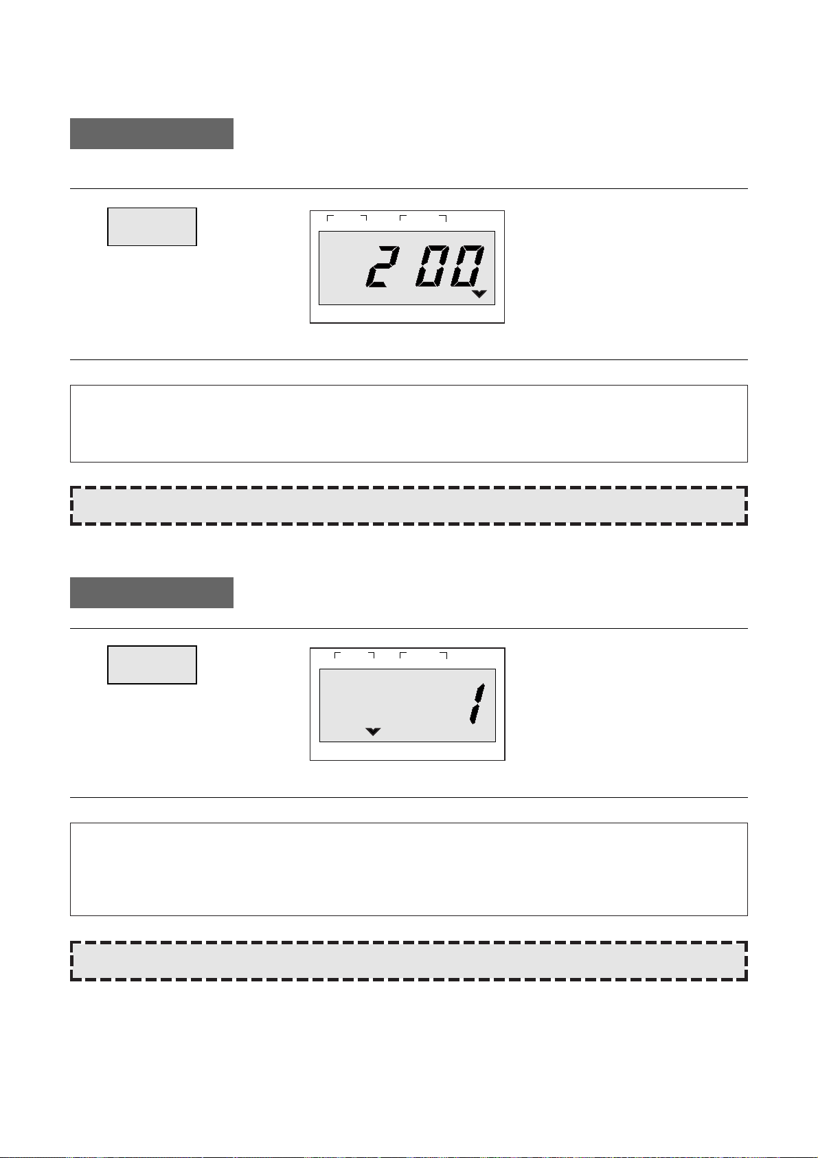
1. Touch FRESH VEGETABLE
pad.
When you touch FRESH VEGETABLE pad, “200” is displayed.
After the 1.5 seconds, the display
changed into cooking time of quantity and the oven starts cooking.
FRESH
VEGETABLE
1. Touch BAKED POTATO pad.
BAKED
POTATO
When you touch BAKED POTATO
pad, “1” is displayed.
After the 1.5 seconds, the display
changed into cooking time of quantity and the oven starts cooking.
oz lb
STAGE
1
2
DEFROST AUTO
START
WEIGHT TIME
LOCK NO CUPS
* BAKED POTATO * (160~180g/ea)
• 1 NO (ea.): Touch BAKED POTATO once.
• 2 NO (ea.): Touch BAKED POTATO twice within 1.5 seconds.
• 3 NO (ea.): Touch BAKED POTATO three times within 1.5 seconds.
* FRESH VEGETABLE *
• 200g: Touch FRESH VEGETABLE once.
• 300g: Touch FRESH VEGETABLE twice within 1.5 seconds.
NOTE: For best results, consult the cookbook.
NOTE: For best results, consult the cookbook.
DO THIS... THIS HAPPENS...
g
g
STAGE
1
2
LOCK
NO CUPS
DEFROST AUTO
WEIGHT TIME
oz lb
START
Page 22

20
1. Touch MENU pad.
When you touch MENU pad, “AC1” is displayed.
The display will then begin blinking.
By repeatedly touching this pad,
you can select other food category
as shown in the chart below.
MENU
CATEGORY FOOD TOUCH PAD
AC-1 BAKED POTATO Touch MENU once.
AC-2 FRESH VEGETABLE Touch MENU twice.
AC-3 SOUP Touch MENU three times.
AC-4 FISH FILLETS Touch MENU four times.
AC-5 MEAT LOAF Touch MENU five times.
1. Touch WEIGHT pad.
When you touch WEIGHT pad,
“1” is displayed.
After the 1.5 seconds, the display
changed into cooking time of quantity and the oven starts cooking.
WEIGHT
* BAKED POTATO *(160~180g/ea)
• 1 NO (ea.): Touch WEIGHT once.
• 2 NO (ea.): Touch WEIGHT twice
within 1.5 seconds.
• 3 NO (ea.): Touch WEIGHT three times
within 1.5 seconds.
* FRESH VEGETABLE *
• 200g: Touch WEIGHT once.
• 300g: Touch WEIGHT twice within 1.5 seconds.
* SOUP *
• 250g: Touch WEIGHT once.
• 350g: Touch WEIGHT twice within 1.5 seconds.
* FISH FILLETS*
• 300g: Touch WEIGHT once.
• 500g: Touch WEIGHT twice within 1.5 seconds.
* MEAT LOAF *
• 500g: Touch WEIGHT once.
• 700g: Touch WEIGHT twice within 1.5 seconds.
AUTO COOK (MENU & WEIGHT)
Auto cook allows you to cook or reheat many of your favorite foods by repeatedly touching menu pad.
After the menu selection, touch chosen pad until number in display is same as desired quantity to cook.
M-TYPE
M-TYPE
DO THIS... THIS HAPPENS...
g
g
1
STAGE
DEFROST AUTO
2
WEIGHT TIME
START
LOCK
NO CUPS
oz lb
DEFROST AUTO
2
WEIGHT TIME
START
oz lb
STAGE
1
LOCK NO CUPS
Page 23

21
This key is for feeding bottle disinfection effect.
At first, detach the nipple from the bottle and pour the 30cc water into each bottle, arrange the bottle symmetrically
on the glass tray and operate.
DO THIS... THIS HAPPENS...
MORE pad: adds for 10 seconds to 20 seconds.
LESS pad: remove for 10 seconds to 20 seconds.
These pad only work one touch cooking and feeding bottle mode. And always input previously.
The safety lock prevents unwanted oven operation such as by small children.
To set, press STOP/CLEAR for 3 seconds, LOCK indicator lights.
To cancel, press STOP/CLEAR for 3 seconds, LOCK indicator goes off.
1. Press STOP/CLEAR pad.
• You can restart the oven by touching START pad.
• Touch STOP/CLEAR once more to erase all instructions.
• You must enter in new instructions.
2. Open the door.
• You can restart the oven by closing the door and touching START.
1. Touch FEEDING
BOTTLE pad.
When you touch FEEDING BOTTLE pad, “2” is displayed.
After the 1.5 seconds, the display
changed into sterilizing time of
quantity and the oven starts sterilizing.
FEEDING
BOTTLE
* FEEDING BOTTLE *
• 2 NO (ea.): Touch FEEDING BOTTLE once.
• 4 NO (ea.): Touch FEEDING BOTTLE twice within 1.5 seconds.
• 6 NO (ea.): Touch FEEDING BOTTLE three times within 1.5 seconds.
NOTE: Oven stops operating when door is opened.
FEEDING BOTTLE
MORE, LESS
CHILD SA TETY LOCK
TO STOP THE OVEN WHILE THE OVEN IS OPERA TING
1
STAGE
LOCK
NO CUPS
DEFROST AUTO
WEIGHT TIME
2
START
g
Page 24

The door lock mechamism is a device has been specially designed to completely eliminate microwave radiation
when the door is opened during operation, and thus to perfectly prevent the danger resulting from the leakage of
microwave.
1. PRIMARY INTERLOCK SWITCH
When the door is closed, the hook locks the oven door. If the door is not closed properly the oven will not operate. When the door is closed, the hook pushes the button of the micro switch. Then the button of the primary
interlock switch bring it under on condition.
Adjustment 1.
When the door is closed, the switch button is pushed by the
hook.
The movement of the switch button should exceed 1.2mm
measured at the top of the button.
22
INTERLOCK MECHANISM FUNCTIONS AND ADJUSTMENTS
Latch
Mounting screw
Button
Primary interlock switch
Hook
1.2mm
Page 25

2. SECONDARY INTERLOCK SWITCH AND INTERLOCK MONITOR SWITCH
When the door is closed, the hook pushes the push lever down ward, and push lever presses the button of the
interlock monitor swich to bring it under “off”, condition and presses the button of the secondary interlock
switch to bring it under “on”, condition.
Adjustment 2.
Interock monitor switch
When the door is closed, the interlock monitor switch should be opend before other switches close.
When the door is closed, the interlock monitor switch should be closed after other switches open.
Secondary interlock switch
The movent of the switch button should exceed 1.2mm measured at the top of the button.
3. ADJUSTMENT STEPS
a) Loosen the two mounting screws.
b) Adjust interliock switch assembly position.
c) Confirm the gap (1.2mm) described above.
d) Make sure that push lever moves smoothly adjustments is completed.
e) Completly tighten the two mounting screws.
4. INTERLOCK SWITCH REPLACEMENT
Whenever safety interlock switches are replaced:
1) Refer to the following diagram.
2) Check the connection of monitor switch after replacement.
3) Perform the electrical continuity check of interlock switches and microwave emission test mentioned in this
manual.
23
NOTE: Microwave emission test should be performed after adjusting interlock machanism. If the microwave
emission exceed 4mW/cm2, readjust interlock mechanism.
COLOR
RED
BLUE
BLACK
WHITE
GRAY
SYMBOL
RD
BL
BK
WH
GY
Secondary
Interlock
Switch
Interlock
Monitor
Switch
Primary
Interlock
Switch
RD
GY
WH
WH
WH
WH
BL
BK
RD
BK
RD RD
Hook
Interlock
monitor
switch
Secondary
interlock
switch
Push lever
Page 26

24
Microwave output power can be checked by indirectly measuring the temperature rise of a certain amount of water
exposed to the microwave as directed below.
PROCEDURE
1. Microwave power output measurement is made with the microwave oven supplied at rated Voltage and operated at its maximum microwave power setting with a load of 1,000 ± 5cc of potable water.
2. The water is contained in a cylindrical borosilicate glass vessel having a maximum material thickness of 3 mm
and an outside diameter of approximately 190 mm.
3. The oven and the empty vessel are at ambient temperature prior to the start of the test.
The initial temperature of the water is 10 ± 2˚C.
It is measured immediately before the water is added to the vessel. After addition of the water to the vessel, the
vessel, the Ioad is immediately placed on the center of the shelf which is in the Iowest normal position.
4. Microwave power is switched on.
5. Heating time should be exactly 52 seconds.
Heating time is measured while the microwave generator
is operatng at full power.
The filament heat-up time for magnetrons is not included.
6. The initial and final water temperatures are selected so
that the maximum difference betwen the ambient and
final water temperatures is 5K.
7. The microwave power output P in watts is calculated from the following formula:
• ▲▲ T is actual temperature rise.
• t is the heating time.
The power measured should be 800W ± 10.0˚C
P=4187 X ▲▲ T / t
CAUTION:
1. Water load should be measured exactly to 1 liters.
2. Input power voltage should be exactly 230 volts as specified.
3. Ambient temperature should be 20 ±
2˚C
(68 ± 3.6F)
MEASUREMENT OF THE MICROWAVE OUTPUT POWER
Tray
Water Load
Page 27

25
PROCEDURE
A) Prepare Microwave Energy Survey Meter, 600cc glass breaker, glass thermometer 100˚C or 212˚F.
B) Pour 275cc ± 15cc of tap water initially at 20 ± 5˚C (68 ± 9˚F) in the 600cc beaker with an inside diameter of
approx. 8.5 cm (3.5 in).
C) Place it at the center of the tray and set it in a cavity.
D) Close the door and operate the oven.
E) Measure the leakage by using microwave energy survery meter with dual ranges, set to 2,450 MHz.
– Measured radiation leakage must not exceed the values prescribed below.
• Leakage for a fully assembled oven with door normally closed must be less than 4mW/cm2.
– When measuring the leakage, always use the 5cm space cone with probe. Hold the probe perpendicular to
the cabinet, door. place the space cone of the probe on the door, cabinet, door seam,along the seam, the
door viewing window, the exhaust air vents, the suction air vents.
– Measuring shonld be in a counter-clockwise
direction at a rate of 1 inch/sec. If the leakage of
the cabinet door seam is unknow, move the
probe more slowly.
– When measuring near a corner of the door, keep the probe perpendicular to the areas making sure the probe
end at the base of the cone does not get closet than 2 inches from any metal.
If it does, erroneous reading may result.
MICROWAVE RADIA TION TEST
WARNING
Make sure to check the microwave leakage before and after repair or adjustment.
• Always, start measuring of an unknown field to assure. Safety for operating personnel from microwave energy.
• Do not place your hands into any suspected microwave radiation field unless the safe density level is known.
• Care should be taken not to place the eyes in direct line with the source of microwave energy.
• Slowly approach the unit under test until the radiometer reads an appreaciable microwave leakage from the unit
under the test.
DEFROSTSTAGE AUTO
1 2
WEIGHT TIME START
LOCK NO CUP g
Beverage
Soup Muffin
Baked
Frozen
Potato
Pizza
Fresh
Beverage
Vegetable
Speedy Cook
Auto Def.
1 2 3
4 5 6
7 8 9
Power
0
Stop/Clear Start
Dinner
Plate
Feeding
Bottle
Clock / A.Start
Page 28

26
WIRING DIAGRAM(SLOW ACTING RELAY TYPE)
POWER SUPPLY:
SINGLE PHASE ONLY
FILTER ASS’Y
FUSE
BR(BK)
BL(WH)
GE(GN)
L
N N
L
GN
GN
BL
BL
BL
RD RD
WH
BK
D.O.M. SWITCH
SECONDARY
INTERLOCK SWITCH
RELAY-2
RELAY-3(SLOW ACTING)
RELAY-1
CONTROL P.W.B. ASS’Y
RD WH
COM
NO
NC
PRIMARY
INTERLOCK
SWITCH(UPPER)
INTERLOCK
MONITOR
SWITCH
RD
HIGH VOLTAGE
TRANSFORMER
RD OR
H.V.
CAPACITOR
MAGNETRON
H.V. DIODE
GY
GY GY
WH
GY
GY
GY
CL GM FM
NOTE RD : RED OR : ORANGE CL : CAVITY LAMP (CONDITION)
WH : WHITE BL : BLUE FM : FAN (BLOWER) MOTOR DOOR : CLOSED
BK : BLACK GY : GRAY GM : GEARED MOTOR COOK : OFF
GN : GREEN GE : GREEN/YELLOW
BR : BROWN
2
3
1
L R
H.V.
FUSE
SLOW ACTING
RESISTOR
BR
BR
BR
Fig. 1
Page 29

WIRING DIAGRAM
27
POWER SUPPLY:
SINGLE PHASE ONLY
FILTER ASS’Y
FUSE
BR(BK)
BL(WH)
GE(GN)
L
N N
L
GN
GN
BL
BL
BL
RD RD
WH
BK
D.O.M. SWITCH
SECONDARY
INTERLOCK SWITCH
RELAY-2
RELAY-1
CONTROL P.W.B. ASS’Y
RD WH
COM
NO
NC
PRIMARY
INTERLOCK
SWITCH(UPPER)
INTERLOCK
MONITOR
SWITCH
RD
HIGH VOLTAGE
TRANSFORMER
RD OR
H.V.
CAPACITOR
MAGNETRON
H.V. DIODE
GY
GY GY
WH
GY
GY
GY
CL GM FM
NOTE RD : RED OR : ORANGE CL : CAVITY LAMP (CONDITION)
WH : WHITE BL : BLUE FM : FAN (BLOWER) MOTOR DOOR : CLOSED
BK : BLACK GY : GRAY GM : GEARED MOTOR COOK : OFF
GN : GREEN GE : GREEN/YELLOW
BR : BROWN
2
3
1
L R
H.V.
FUSE
Fig. 1-1
Page 30

28
CIRCUIT DESCRIPTION
Refer to the “WIRING DIAGRAM” (Fig. 1) on page 26~27.
MICROWAVE COOKING
TIME COOKING
1. When the food is placed inside the oven and door is closed.
1) The low voltage transformer supplies the necessary voltage to the touch control circuit when the power cord
is plugged in.
2) The contacts of the interlock monitor switch open.
This switch creates short circuit to blow 12A fuse and stop magnetron oscillation when door is opened during
operation under abnormal condition (i.e. the contacts of primary interlock switch do not open the circuit).
3) The contacts of primary interlock switch close the primary circuit.
2. When cooking cycle, power and time are set by touching the function pads and the desired numerical
pads.
1) The function indicating bars are located on the digitron light to indicate that function have been set.
2) The time you set appears in the display window.
3) The touch control circuit memorizes the cooking program you set.
3. When the start pad is touched.
* The RELAY “1”, “2” are controlled by the touch control circuit.
1) 230VAC is applied to the high voltage transformer through the contacts of RELAY “1”.
2) Fan motor starts rotating and cools the magnetron by blowing the air coming form the intake on the rear plate
hold.
3) The oven lamp light the inside of the oven.
4) Indicator light turns on to indicate function operation. Cooking time starts count down.
5) 3.3 Volts AC is generated from the filament winding of the high voltage transformer. This filament voltage is
applied to the magnetron to heat the magnetron filament through two noise prventing choke coils.
6) A high voltage of 2000 Volts AC is generated in the secondary of high voltage transformer and this sec-
ondary voltage is increased by the action of the diode and the charging of the high voltage capacitor. This
resultant DC voltage is then applied to the anode of the magnetron. As shown in Fig. 2 the first half cycle of
the high voltage produced in the high voltage transformer secondary charges the high voltage capacitor.
Current flow is in the direction of the dotted-line during the second half cycle, the voltage produced by the
transformer secondary, and the charge of the high voltage capacitor are combined and applied to the magnetron as shown by the solid line so that oscillations begin. The disturbance wave generated by the
mangetron is prevented by the choke coils of 3.2µH, filter capacitor of 16pF and the magnetron’s shielded
case so that TV and radio programs are not impaired by noise.
Page 31

29
Fig. 2
The touch control circuit controls the ON-OFF time of RELAY “1” in order to vary the output power of the
microwave oven from “power level 1“ to “HI (100%) power”.
One complete ON and OFF cycle of the RELAY “1” is 29 seconds. The relation between indications on the control
panel and the output of the microwave oven is as shown in Fig. 3
HIGH VOLTAGE
TRANSFORMER
RD RD
H.V
FUSE
H.V.
CAPACITOR
MAGNETRON
H.V. DIODE
Page 32

30
0 0/29 (0%)
1 3/29 (10%)
2 5/29 (17%)
3 8/29 (28%)
4 11/29 (38%)
5 14/29 (48%)
6 17/29 (59%)
7 20/29 (69%)
8 23/29 (79%)
9 26/29 (90%)
HI 29/29 (100%)
POWER LEVEL
Fig. 3
AUTO DEFROST CYCLE
When auto defrost is selected and the desired defrosting time is chosen, the automatic cycle divides the defrosting
time into 5 periods of alternating defrost and stand times, by cycling on and off.
4. When the door is opened during cooking.
1) The primary interlock switch is opened to cut off primary voltage to the high voltage transformer to stop
microwave oscillation.
2) The secondary interlock switch is opened to give the door open information to touch control circuit. The con-
tacts of the RELAY “1” and “2” open, the display stops counting down.
3) Fan motor and turn table stop rotating.
4) The oven lamp turns off.
5) As soon as the door is opened, the interlock monitor switch contacts close and creats the short circuit.
6) If the contacts of primary interlock switch malfunction the 12A fuse blows open due to the large current surge
caused by the short circuit activation, and this in turn stops magnetron oscillation (Fig. 1).
5. When the STOP/CLEAR pad is touched during cooking.
1) The touch control circuit cuts the voltage supplied to the RELAY “1” coil and causes the magnetron to stop
oscillating.
2) RELAY “2” turns off.
3) The display will show the time of day. If you don’t set the clock, the display will show a colon.
4) The oven lamp turns off.
5) Fan motor and turn table motor stop rotating.
OUTPUT POWER
AGAINST FULL POWER
RELAY “1” TURN ON, OFF TIME
ON
OFF
ON
3S
OFF
ON
OFF
ON
OFF
ON
OFF
ON
OFF
ON
OFF
ON
OFF
ON
OFF
ON
OFF
ON
OFF
5S
8S
11S
14S
17S
20S
23S
26S
29S
29S
Page 33

31
– Cautions to be observed when trouble shooting.
Unlike many other appliances, the microwave oven is a high-voltage, high-current equipment. It is com pletely
safety during normal operation. However, carelessness in servicing the oven can result in an electeric shock or
possible danger from a short circuit.
You are asked to observe the following precautions carefully.
(1) Always remove the power plug from the outlet before servicing.
(2) Use an insulated screwdriver which is attached to iron plate, and wear rubber gloves when servicing the high
voltage side.
(3) Warning about the electric charge in the high voltage capacitor. When inspecting and repairing the high voltage
side, always short the capacitor terminals and make sure of discharge.
1. Check the grounding.
Do not operate on a 2-wire extension cord.
The microwave oven is designed to be used when
grounded.
It is imperative, therefore, to makes sure it is grounded
properly vefore before begining repair work.
2. Warning about the electric charge in the high
voltage capacitor.
For about 30 seconds after the operation stops, electric
charge remians in the high voltage capacitor. When
replacing or checking parts, short between oven chassis
and the negative high terminal of the high voltage capacitor, by using a properly insulated screw driber to discharge.
(4) When the 12 Amp. fuse is blown out to operation of the monitor switch; replace primary, and monitor switch.
Refer to 22 page for the necessary adjustment.
(5) After repair or replacement of parts, make sure that the screws are properly tightened, and all electrical con-
nections are tightened.
(6) Do not opertate without cabinet.
SAFETY PRECAUTIONS FOR DISASSEMBLY AND REP AIR
Short
CAUTION: Service personnel should remove their watches whenever working close to or repairing the mag-
netron.
WARNING: When servicing the appliance, need a care of touching or replacing high potential parts because
of electrical shock of exposing microwave. These parts are as follows–H.V. Thansformer,
Magnetron, H.V. Capacitor, H.V. Diode.
Page 34

32
1. To remove cabinet.
Remove three screws on cabinet back.
2. To remove door assembly.
1) Remove two screws 3 which secure the top hinge
seoppr 2.
2) Remove the door assembly 1 from the top plate of
cavity.
3) Reverse the above for reassembly.
3. To remove door parts.
DISASSEMBLY AND ASSEMBLY
NOTE: After replacing the door preform a check of
correct alignment with the hinge and cavity
front face.
F07
2
1
3
F02
F08
A00
F41
Page 35

33
(1) Remove the gasket door (A07) from door weld ass’y (A05).
(2) Remove the barrier screen inner (A06) from door weld ass’y (A05).
(3) Remove the hook spring (A09) and the hook (A08).
(4) Remove the hinge stopper to ass’y (A04).
(5) Remove the door frame (A01) from door weld ass’y (A05).
(6) Remove the barrier screen outer (A02) and the supporter barrier screen outer (A03).
(7) Reverse the above steps for reassenbly.
4. Method to reduce the gap between the door seal
and the oven front surface.
(1) To reduce gap located on part ‘A’
1) Loosen two screws on the top hinge stopper, and
then push the door to contact the door seal to oven
front surface.
3) Tighten two screws.
(2) To reduce gap located on part ‘B’.
1) Loosen three screws in under hinge stopper, and then the door to contact the door seal to oven front surface.
2) Tighten three screws.
(3) To reduce gap located on part ‘C’. (See Fig. A)
1) Loosen a screw on the interlock switch assembly located at the bottom of the oven body.
2) Draw the interlock switch assembly inward as possible with hook on the door bottom.
3) Tighten a screw.
(4) To reduce gap located on part ‘D’. (See Fig. B)
1) Loosen a screw on the interlock switch assembly located at the top of the oven body.
2) Follow step (3) 2) and 3).
Interlock
monitor
switch
Secondary
interlock
switch
Hook
Mounting screw
Mounting
screw
Hook
Primary
interlock
switch
Fig. A Fig. B
NOTE: A small gap may be acceptable if the microwave leakage does not exceed 4mW/cm
2
.
A
B
D
C
DEFROSTSTAGE AUTO
1 2
WEIGHT TIME START
LOCK NO CUP g
Beverage
Soup Muffin
Baked
Frozen
Potato
Pizza
Fresh
Beverage
Vegetable
Speedy Cook
Auto Def.
1 2 3
4 5 6
7 8 9
Power
0
Stop/Clear Start
Clock / A.Start
Dinner
Plate
Feeding
Bottle
Page 36

34
5. To remove control panel parts.
(1) Remove the screw which secure the control panel,
push up two snap fits and draw forward the control
panel assembly.
(2) Remove the door open lever (B05) from the control panel (B02).
(3) Remove four screws (B04) which secure the P.C.B. ass’y (B03) to control panel.
(4) Disconnect membrane (B01) tail from the connector of the P.C.B. ass’y (B03).
(5) Detach membrane (B01) from the control panel (B02).
(6) Remove the door open button (B07) and button spring (B06) from the control panel (B02).
(7) Remove the above steps for reassembly.
NOTE: Do not attempt to remove switch membrane except for replacement.
Page 37

35
6. To remove high voltage capacitor .
(1) Remove the screw 1 which secure the grounding ring
terminal of H.V. diode 4 and capacitor holder 2.
(2) Remove the capacitor holder 2 with H.V. capacitor
3.
(3) Reverse the above steps for reassembly.
High voltage circuit wiring
7. To remove magnetron.
(1) Remove three screws 2 which secure magnetron 1.
(2) Pull out the magntron 1 from the wave guide.
(3) Reverse the above steps for reassembly.
1
2
1
2
3
4
MAGNETRON
H.V. CAPACITOR
F13
F14
F15
F16
H.V.
DIODE
H.V. TRANSFORMER
F06
F07
Page 38

36
8. To remove fan motor assembly.
(1) Remove two screws 1 which secure the back cover 3 from the cavity outer.
(2) Remove two screws 2 which secure the fan motor 4 from the back cover 3.
(3) Pull out the fan 5 from the motor 4.
(4) Remove the above steps for reassembly.
9. To remove thransformer .
(1) Remove the four screws 2 holding the H.V. trams-
former 1.
(2) Remove the transformer 1.
(3) Reverse the above steps for reassembly.
CAUTION: Never install the magnetron without the metallic gasket plate which is packed with each mag-
netron to prevent microwave.
Whenever repair work is carried out on magnetron, check the microwave leakage.
It shall not exceed 4mW/cm2for a fully assembled oven with door normally closed.
1
2
1
3
5 4
1
2
Magnetron
Metallic
gasket
plate
antenna
Wave guide
Magnetron antenna
Cooling fin
Filament
terminalMagnetron
Metallic gasket plate
F12
F11
F08
F09
F08
F10
F17
F18
Page 39

37
Following the procedures below to check if the oven is defective or not.
1. Check grounding before checking trouble.
2. Be careful of the high voltage circuit.
3. Discharge the high voltage capacitor. (see page 31)
4. When checking the continuity of switches or of the high voltage transformer, disconnect one lead wire from
these parts and then check cintinuity with the AC plug removed. To do otherwise may result in false reading or
damage to your meter.
5. Do not touch any part of the circuity on the touch control circuit since static electric discharge may damage this
control panel.
Always touch yourself to ground while working on this panel to discharge any static charge built up in your
body.
First of all operate the microwave oven following the correct operation described in pages 6~21 by time cooking, in
order to find the exact cause if any trouble.
(TROUBLE 1) The following visual conditions indicate a probable defective touch control circuit
or membrane switch assembly.
TROUBLE SHOOTING GUIDE
1. Incomplete segments.
(A) Segments missing.
(B) Partical segments missing.
(C) Digit flickering other thay normal fluorescent
slight flickering.
(D) “:0” does not display when power is on.
2. A distinct change in the brightness of one or more
numbers in the display.
3. One or more digits in the display are not on when
they should be.
4. Display indicates a number different from one
touched.
5. For example, touch 5 and 3 appears in the display.
6. Specific numbers (for example 5 and 3 )will not dis-
play when the panel is touched.
7. Display does not count down or up with time cook-
ing or clock operation.
8. Oven is programmable and cooks normally but no
display shows.
9. Display obviously jumps in time while counting
down
10. Display counts down noticeably too fast while
cooking.
11. Display can not shift from the first stage coking to
the third stage cooking while 3 phase cooking
(including defrost).
12. Display does not show the time of day when dear
pad is touched (in clock mode).
13. Oven lamp and fan motor and turn table motor do
not stop although cooking is finished.
Check if the RELAY “2” contacts close if they are
close, replace touch control circuit.
DEFROST AUTO
START
WEIGHT TIME
1
LOCK NO CUPS
g
STAGE
2
Page 40

38
(TROUBLE 2) Digital readout display does not show programming, even if the membrane key-
board is programmed by touching proper pads.
MEMBRANE KEYBOARD CHECK PROCEDURE : M-TYPE
1. Check the pad termination order and nomenclature.
Fig. 4
Check Result Cause Remedy
Replace
control
box sub-assembly
Check each pad for
continuity of the
membrane keyboard
for the following
keyboard check
procedure
Condition
Display does not
show programming
at all, even if
keyboard is
touched
Normal
Malfunction
of touch control
circuitry of
control box
sub-assembly
Replace the membrane
keyboard
Abnormal
Malfunction
of the membrane keyboard
NOTE: Before following the particular steps listed above in the trouble shooting guide for the membrane key-
board, failure, please check for the continuity of each wire-harness between the membrane keyboard
and control box assembly.
A
1
1 2
DEFROSTSTAGE AUTO
WEIGHT TIME START
B
C
D
E
F
G
H
I
J
K
2
3
4
5
6
7
8
9
10
11
PAD Termination PCB connector
LOCK NO CUP g
Auto Cook
1. Raked Potato
2, Fresh Vegetable
3. Soup
4. Fish Fillets
5. Meat Loaf
Dinner
Plate
Muffin
Speedy Cook
Frozen
Pizza
Beverage
Menu
Weight
Auto Def.
popcorn
1 2 3
4 5 6
7 8 9
0
Stop/Clear Start
Feeding
Bottle
PowerClock / A.Start
Page 41

39
2. Type of encoding and pad names.
Fig. 5 Key Matrix
The membrane keyboard consists of 26 keys whose configurations are described above and provide 11 pad terminations to be connected to the touch control circuit as Fig. 4.
3. Key check procedure.
To determine if the membrane keyboard is defective or not, check the continuity of each pad (KEY) contacts with a
multimeter.
1) 5 pad : Between A and F
2) 0 pad : Between A and G
3) POWER pad : Between A and H
4) SPEEDY COOK pad : Between A and I
5) FEEDING BOTTLE pad : Between A and J
6) MENU pad : Between A and K
7) 6 pad : Between B and F
8) 1 pad : Between B and G
9) MUFFIN pad : Between B and I
10) WEIGHT pad : Between B and K
11) 7 pad : Between C and F
12) 2 pad : Between C and G
13) BEVERAGE pad : Between C and I
14) MORE pad : Between C and J
15) AUTO DEFROST pad : Between C and K
16) 8 pad : Between D and F
17) 3 pad : Between D and G
18) DINNER PLATE pad : Between D and H
19) FROZEN PIZZA pad : Between D and I
20) LESS pad : Between D and J
21) CLOCK/A.START pad : Between D and K
22) 9 pad : Between E and F
23) 4 pad : Between E and G
24) POPCORN pad : Between E and I
25) START pad : Between E and J
26) STOP/CLEAR pad : Between B and K
E D C B A
9 8 7 6 5
F
4 3 2 1 0
G
H
POPCORN
I
START
J
STOP/
CLEAR
K
DINNER
PLATE
FROZEN
PIZZA
LESS
CLOCK/
A.START
BEVERAGE
MORE
AUTO
DEFROST
POWER
MUFFIN
SPEEDY
COOK
FEEDING
BOTTLE
WEIGHT MENU
Page 42

40
MEMBRANE KEYBOARD CHECK PROCEDURE : Q-TYPE
1. Check the pad termination order and nomenclature.
Fig. 4-1
A
B
C
D
E
F
G
H
I
J
K
1
2
3
4
5
6
7
8
9
10
11
PAD Termination PCB connector
DEFROSTSTAGE AUTO
1 2
WEIGHT TIME START
LOCK NO CUP g
Popcorn
Vegetable
Baked
Potato
Fresh
Beverage
Speedy Cook
Auto Def.
Soup Muffin
Frozen
Pizza
1 2 3
4 5 6
7 8 9
Power
Stop/Clear Start
0
Clock / A.Start
Dinner
Plate
Feeding
Bottle
Page 43

41
2. Type of encoding and pad names.
Fig. 5-1 Key Matrix
The membrane keyboard consists of 27 keys whose configurations are described above and provide 11 pad terminations to be connected to the touch control circuit as Fig. 4-1.
3. Key check procedure.
To determine if the membrane keyboard is defective or not, check the continuity of each pad (KEY) contacts with a
multimeter.
1) 5 pad : Between A and F
2) 0 pad : Between A and G
3) POWER pad : Between A and H
4) SPEEDY COOK pad : Between A and I
5) FEEDING BOTTLE pad : Between A and J
6) 6 pad : Between B and F
7) 1 pad : Between B and G
8) SOUP pad : Between B and H
9) MUFFIN pad : Between B and I
10) 7 pad : Between C and F
11) 2 pad : Between C and G
12)
FRESH VEGETABLE
pad : Between C and H
13) BEVERAGE pad : Between C and I
14) MORE pad : Between C and J
15) AUTO DEFROST pad : Between C and K
16) 8 pad : Between D and F
17) 3 pad : Between D and G
18) DINNER PLATE pad : Between D and H
19) FROZEN PIZZA pad : Between D and I
20) LESS pad : Between D and J
21) CLOCK/A.START pad : Between D and K
22) 9 pad : Between E and F
23) 4 pad : Between E and G
24) BAKED POTATO pad : Between E and H
25) POPCORN pad : Between E and I
26) START pad : Between E and J
27) STOP/CLEAR pad : Between E and K
E D C B A
9 8 7 6 5
F
4 3 2 1 0
G
BAKED
POTATO
H
POPCORN
I
START
J
STOP/
CLEAR
K
DINNER
PLATE
FROZEN
PIZZA
LESS
CLOCK/
A.START
FRESH
VEGETABLE
BEVERAGE
MORE
AUTO
DEFROST
SOUP
MUFFIN
POWER
SPEEDY
COOK
FEEDING
BOTTLE
WEIGHT MENU
Page 44

42
(TROUBLE3) The oven not operate at all; Display window does not display any figures and any
inputs can not be accepted.
Check Result
Cause Remedy
Replace Primary
Interlock Switch
and Secondary
Interlock Switch
and Monitor
Interlock Switch.
Check continuity
Interlock Monitor
switch with door
closed.
Condition
12A fuse
blows
Continuity
No
continuity
Malfunction of
Interlock monitor
switch
Replace
Primary
Interlock Switch
and Monitor
Interlock Switch.
Check continuity
of both Primary
Interlock Switch
contact with door
partially open until
interlock monitor
switch contact
close.
Continuity
Shorted contacrs
of primary interlock switch.
(Replace 12A fuse)
Defective high
voltage transformer
Check continuity
of primary
winding of low
voltage transformer.
0 Ω or
infinite
Approx
110~130Ω
(normal)
Shorted of open
winding
Replace
Normal
Replace Low
Voltage
Transformer
Replace
12A fuse
again
blows
Defective high
voltage capacitor
Disconnect one
side of the lead
wire connected
from transformer
to the high voltage
capacitor and
operate the unit.
NOTE 1
NOTE 1
NOTE 1: All these switches must be replaced at the same time, please refer to page 22 and 23 for adjust-
ment instructions.
Page 45

43
Check Result
Cause Remedy
Replace
Check continuity
of oven
thermostat
Condition
No
Continuity
Defective oven
thermostat.
Replace
Check continuity
of power supply
cord.
No
Continuity
Open power
supply cord.
Replace
Normal
Defective touch
control circuit
Replace
Display do not
shown countdown
Malfunction of
secondary
interlock switch
Outlet has
proper
voltage
Fuse does
not open
Check Result
Cause Remedy
Adjust or
replace
Check continuity
of parimary
interlock switch
Condition
No
Continuity
Malfunction of
Primary interlock
switch
Replace
Check D.C.
voltage being
supplied to
RELAY “2” coil.
OV
Defective touch
control circuit
Replace
Approx.
+12VDC
Faulty contacts
of RELAY “2”
or open relay
coil
Turn table
motor
fan motor and
oven lamp do
not turn on
Page 46

44
Check Result
Cause Remedy
Replace
Check continuity
of primary winding
of high voltage
transformer and
touch control
circuit
Condition
Turn table
motor,
fan motor and
oven lamp turn
on for a
second when
the start pad
is tapped
No
Conntinuity
Open winding
Replace Normal
Defective touch
control circuit
Check Result
Cause Remedy
Check continuity
of connecting wire
of magnetron.
Condition
No
microwave
oscillation
Continuity
Replace
Check the isolation of filament
winding of high
voltage transfrmer
No
Good
Defective
high voltage
transformer
Replace
Good
No
Continuity
Defective
magnetron
Replace
Check continuity
of filament of
magnetron.
No
Continuity
Defective
magnetron
Replace
Check the isolation of filament
terminal of high
voltage transformer
No
Continuity
Defective
high voltage
transformer
Replace
Check the diode
for continuity
in the reverse
and normal
directions
Continuity
in the
reverse
direction
Defective
high voltage
diode
Continuity
Continuity
Page 47

45
(TROUBLE 6) Micrwave Output power is low .
First of all, check if output power is really low following “measurement of the
microwave output power” on page 24.
RELAY “1” OFF TIME
29
26 (Seconds)
24
21
18
15
12
9
6
3
0
Check Result
Cause Remedy
Customer
education
Check the power
source voltage
with magnetron
oscillating
Condition
Output
power is low.
Lower than
207 volts
Descrease in
power source
voltage
Normal
Replace
Check the timing
periods of the
RELAY “1” coil
Abnormal
NOTE 3
Defective touch
control circuit
Replace depending on the result of
output test
Normal
Aging change
of magnetron
NOTE 2: The following chart shows the timing periods of the RELAY “1”.
NOTE 3: Interlock monitor switch must be replaced when fuse is blown out.
POWER
0
1
2
3
4
5
6
7
8
9
HI
RELAY “1” ON TIME
0
3 (Seconds)
5
8
11
14
17
20
23
26
29
Page 48

1. High voltage is present at the high voltage terminal of the high voltage transformer during any cooking cycle.
2. It is neither necessary nor advisable to attempt measurement of the high voltage.
3. Before touching any oven components or wiring, always unplug the oven from its power source and discharge
the capacitor (see page 31).
46
COMPONENT TEST PROCEDURE
1. High voltage transformer
(A) Remove connections from the transformer termi-
nals and check continuity.
(B) Normal readings should be as follows:
Secondary winding..........Approx. 120.0Ω ± 10%
Filament winding...............................Approx. 0Ω
Primary winding.................................Approx. 0Ω
2. High voltage capacitor
(A) Check continuity of capacitor with meter on the
highest OHM scale.
(B) A normal capacitor will show continuity for a short
time, and then indicate 9MΩ once the capacitor is
charged.
(C) A shorted capacitor will show continuous continu-
ity.
(D) An open capacitor will show constant 9MΩ.
(E) Resistance between each terminal and chassis
should be infinite.
3. High voltage diode
(A) Isolate the diode from the circuit by disconnecting
the leads.
(B) With the ohmmeter set on the highest resistance
scale, measure the resistance across the diode
terminals.
Reverse the meter leads and again observe the
resistance reading. meter with 6V, 9V or higher
voltage batteries should be used to check the front-
back resistance of the diode, otherwise an infinite
resistance may be read in both directions. A nor-
mal diodes resistance will be infinite in one direc-
tion and several hundred KΩ in the other direction.
4. Magnetron
For complete magnetron diagnosis, refer to
“Measurement of the Microwave Output Power”.
(Page 24) Continuity checks can only indicate and
open filament or a shorted magnetron. To diagnose for an open filament or shorted magnetron.
(A) Isolate magnetron from the circuit by disconecting
the leads.
(B) A continuity check across magnetron filament ter-
minals should indicate ohm or less.
(C) A continuity check between each filament terminal
and magnetron case should read open.
5. Interlock monitor switch
The interlock switch can be checked with an ohmmeter. Isolate the switch and then connect the
meter leads to the common (COM) and normally
close (NC) terminals of the switch. The meter
should indicate an open circuit with the door closed
and a closed circuit with the door opened.
6. Primary and secondary interlock switch
The primary and secondary interlock switch can be
checked with an ohmmeter. Isolate the switch and
connect the meter leads to the common (COM) and
normally open (NO) terminals of the switch.
The meter should indicate an openn circuit with the
door opened and a closed circuit with the door
closed. In case improper operation is indicated,
make the necessary switch adjustment or replacement.
Page 49

• Disconnect the oven from the power supply.
• You can test continuity of safety interlocks and monitor switch by using switch tester or ohmmeter.
• The switch operation is checked by the lamp on/off of resistance zero/unlimited.
• The sequence of check is interlock monitor switch; primary and secondary interlock switches check.
• Make circuits like Fig. a, Fig. b, Fig. c for tests.
47
SAFETY INTERLOCK CONTINUITY TEST
1) In case of interlock monitor check.
(Lamp on or zero resistance)
(ohmmeter)
– Fig. a –
Condition: 1) Door is opened.
2) Common terminal of the monitor
switch disconnected.
3) In case of secondary interlock switch.
(ohmmeter)
– Fig. c –
Condition: 1) Door is closed.
2) In case of primary interlock check.
(Lamp on or zero resistance)
(ohmmeter)
– Fig. b –
Condition: 1) Door is closed.
* (Schematic diagarm of S/W tester)
POWER
SUPPLY
CORD
POWER
SUPPLY
CORD
POWER
SUPPLY
CORD
PRIMARY
INTERLOCK S/W
PRIMARY
INTERLOCK S/W
PRIMARY
INTERLOCK S/W
NO
NO
NO
COM
COM
COM
NC
NC
NC
INTERLOCK
MONITOR
S/W
INTERLOCK
MONITOR
S/W
INTERLOCK
MONITOR
S/W
SECONDARY
INTERLOCK
S/W
SECONDARY
INTERLOCK
S/W
SECONDARY
INTERLOCK
S/W
CONTACT
LEAD
LAMP
S/W
BATTERY
Page 50

48
PRINTED CIRCUIT BOARD
1. CIRCUIT CHECK PROCEDURE
1) Low V oltage Transformer (DMR-602FS) Check.
The low voltage transformer is located on the P.C.B.
Measuring condition:Input voltage: 230V
Frequency: 50Hz
2) V oltage Check
Key check point
CHECK METHOD
NOTE 1: Secondary side voltage of the low voltage transformer changes in proportion to fluctuation
of power source voltage.
NOTE 2: The allowable tolerance of the secondary voltage is within ±5% of norminal voltage.
NOTE : Each measure point must be measured with GND points.
Voltage
Terminal LOAD NO LOAD
3 – 5 50Hz Input 27 V AC 30V AC
NO. MEASURE POINT WAVE FORM REMEDY REMARK
1 MP1 DC 5V ± 0.25 Replace VL1, EC1, C4, C6 NO LOAD
2 MP2 DC 14V ±1.0 Replace D13, D14, EC2 NO LOAD
NO. CHECK POINT REMARK
1 IC1 PIN 7, 41, 42 5VDC
2 IC1 PIN 11 GND
3 IC1 PIN 23
4 IC1 PIN8 or 9
T:20ms(50Hz)
Page 51

49
3) Display problems
The display trouble shooting data
4) When there is no microwave oscillation.
(1) When touching "ST AR T" pad, oven lamp does not turn on.
Fan motor and turntable motor do not rotate, but cook indicator in display comes on.
* Cause: RELA Y "2" does not operate.
DISPLA Y NAME MICOM OUTPUT
TROUBLE
& PIN NO. IN PIN NO.
ST AGE 1, LOCK don't come on. Digit 1 (G1), 10 31
ST AGE 2, NO don't come on. Digit 2 (G2), 1 1 32
WEIGHT DEFROST, CUPS don't come on. Digit 3 (G3), 14 30
TIME DEFROST doesn't come on. Digit 4 (G4), 12 33
AUTO START, g don't come on. Digit 5 (G5), 13 29
SEGMENT "a" doesn't come on from G1 to G5. SEGMENT a, 7 20
SEGMENT "b" doesn't come on from G1 to G5. SEGMENT b, 6 19
SEGMENT "c" doesn't come on from G1 to G5. SEGMENT c, 5 18
SEGMENT "d" doesn't come on from G1 to G5. SEGMENT d, 4 17
SEGMENT "e" doesn't come on from G1 to G5. SEGMENT e, 3 16
SEGMENT "f" doesn't come on from G1 to G5. SEGMENT f, 2 14
SEGMENT "g" doesn't come on from G1 to G5. SEGMENT g, 1 13
LOCK, NO, CUPS, g don't come on. LOWER BAR h, 9 15
ST AGE1, STAGE2, TIME DEFROST , WEIGHT UPPER BAR i, 8 21
DEFROST, AUTO START don't come on.
NO. CAUSE MEASUREMENT RESULT REMEDY
1 Defective Display Refer to "The display Replace P.C.B.
trouble shooting data" assembly .
below.
Display layout
(Top View)
Q12
Page 52

Fig. 6 Measurement Point
50
MP1
GNDMP2
<BOTTOM VIEW>
KOR-618M0P
Page 53

51
CHECK METHOD
(2) When touching "ST AR T" pad, oven lamp turns on.
Fan motor and turntable rotate and cook indicator in display comes on.
* Cause: RELA Y"1" does not operate.
CHECK METHOD
5) When the door is opened during operation, the count down timer does not stop.
CHECK METHOD
POINT
A
ST AGE
RELA Y "2" ON GND
RELA Y "2" OFF +12V DC
POINT
A B
ST AGE
RELA Y "1" ON +5VDC GND
RELA Y "1" OFF GND +12VDC
POINT
A B
ST AGE
1) DOOR OPENED OPEN 5VDC
2) DOOR CLOSED CLOSE GND
CHECK
METHOD REMEDY
NO.
1
Check the stage (ON, OFF) of the secondary Replace secondary
Interlock switch by resistance measurement. interlock switch
Page 54

52
6) When the digital clock does not operate properly
If clock does not keep exact time, you must check resistor R21, R22 and capacitor C5.
POINT WAVEFORM
A
T:20ms(50Hz)
Page 55

53
2. P.C.B. CIRCUIT DIAGRAM(M-TYPE)
CN1(D.O.M)
IC1
9 8 7 6 5
4 3 2 1 0
DINNER
PLATE
POWER
POPCORN
FROZEN
PIZZA
BEVERAGE
MUFFIN
SPEEDY
COOK
FEEDING
BOTTLE
START LESS MORE
STOP/
CLEAR
CLOCK/
A.START
AUTO
DEFROST
MENUWEIGHT
3
7
10
38 R41
SLOW ACT
SLOW ACTING RELAY
* O : INSERT, X : NOT INSERT
* TOLERANCE OF RESISTANCES(for not marked here) : ±5%, WATTAGE : 1/6W
OPTION 618M/Q 619M/Q
SJ1 MODEL O O
SJ2 SELECT X X
SJ3 g/lb SELECT lb MODE : O, g MODE : X
Page 56

54
2. P.C.B. CIRCUIT DIAGRAM(Q-TYPE)
CN1(D.O.M)
IC1
3
7
10
38 R41
SLOW ACT
SLOW ACTING RELAY
* O :INSERT, X : NOT INSERT
* TOLERANCE OF RESISTANCES(for not marked here) : ±5%, WATTAGE : 1/6W
OPTION 618M/Q 619M/Q
SJ1 MODEL O O
SJ2 SELECT X X
SJ3 g/lb SELECT lb MODE : O, g MODE : X
BAKED
POTATO
POP
CORN
FRESH
VEGETABLE
SOUP
FEEDING
BOTTLE
Page 57

55
3. COMPONENT INFORMA TION
1) Transistor
2) Diode and Zener Diode
3) Digital Transistor
Q1-Q8
Q10-Q13
Page 58

56
4. PRINTED CIRCUITS BOARD
KOR-618M0P
Page 59

57
5. P.C.B. LOCATION No.
NO PART NAME REF NO. SPECIFICATION PART CODE Q'TY
1 RESISTOR R11, R15, R17, R24 1K, 1/6W, 5% RD-AZ102J- 4
2 RESISTOR R13, R16, R22 10K, 1/6W, 5% RD-AZ103J- 3
3 RESISTOR R21 4.7K, 1/6W, 5% RD-AZ472J- 1
4 RESISTOR R10, R18, R19, R20 100K, 1/6W, 5% RD-AZ104J- 4
5 RESISTOR R14 1M, 1/6W, 5% RD-AZ105J- 1
7 RESISTOR R12 100, 1/6W, 5% RD-AZ101J- 1
8 RESISTOR R23 51, 1/4W, 5% RD-4Z510J- 1
9 RESISTOR R1,2,3,4,5,6,7,8,9 330 1/4W, 5% RD-4Z331J- 9
10 R ARRAY RA1 RGLD6X104J RA-87X104J- 1
11 DIODE D1-D6,D10,D11D12 1N4148M DZN4148M- 9
12 DIODE D7,D8,D9,D13,D14 1N4002A DZN4002A- 5
13 DIODE ZENER ZD2 5.1VB, 1/2W DZTZ5R1B- 1
14 DIODE ZENER ZD1 3.9VB, 1/2W DZTZ3R9B- 1
15 TRANSISTOR LVT1 DMR-602FS 5EPU035408 1
16 CAPACITOR CERAMIC EC1 100MF 16V RSS CEXF1C101V 1
17 CAPACITOR CERAMIC EC2 1000MF 25V RSS CEXF1E102V 1
18 P. C. B BARE M152 M152 3514315400 1
19 LED DISPLAY DP1 DDG611Q DDDG611Q00 1
20 C ARRAY CA1 F6 102Z CN6XB-102M 1
21 TRANSISTOR Q9 KTA1270Y TZTA1270Y- 1
22 TRANSISTOR Q1-Q5 KRA110M TZRA110M-- 5
23 TRANSISTOR Q6-Q8, Q10-Q13 KRC106M TZRC106M-- 7
24 CONNECTOR WAFER CN1 YW396-02V 3519150520 1
25 CONNECTOR WAFER CN3 YM396-05AV 3519150510 1
26 CONNECTOR WAFER CN2 FCZ254-11 441M367160 1
27 CONNECTOR WAFER RY3(COIL PART) 35312-0370 3519105900 1
28 BUZZER BZ1 BM-20K 3515600100 1
29 REGULATOR VL1 MC7805C 1CPMC7805C 1
30 CAPACITOR CERAMIC C1 50V 473 AXIAL CCZF1H473Z 1
31 CAPACITOR CERAMIC C2, C3, C4, C5, C6 50V 104 AXIAL CCZF1H104Z 5
32 RESONATOR CR1 KBR-4.0MKSTF 5PKBR40MKS 1
33 SW RELAY RY1 G5J-1-TP-M12V 5SC0101108 1
34 SW RELAY RY2 G5B-DC12V 5SC0101110 1
35 SW RELAY RY3 G5J-1-TP-M12V 5SC0101108 1
36 IC MICOM IC1 HD404054A34S 147S611MQ1 1
* D7, Q10, RY3 INSERT ONLY SLOW ACTING RELAY
Page 60

58
1. Door Assembly
REF NO. PART NAME PART CODE DESCRIPTION Q’TY REMARKS
A01 FRAME DOOR
3512202030 ABS
1
KOR-618M,Q
3512202040 ABS KOR-619M,Q
A02 BARRIER-SCREEN *O 3517003050 ACRYL 1
A03 SUPPORTER BARR-S *O 3515304610 PP 1
A04 STOPPER HINGE *T AS 3515201500 KOR-6115OS 1
A05 DOOR WELD AS 3511705500 KOR-6115OS 1
A06 BARRIER-SCREEN *I 3517002800 POLYESTER T0.1 1
A07 GASKET DOOR 3512300200 PP 1
A08 HOOK 3513100700 POM 1
A09 SPRING HOOK 3515101300 PW1 1
EXPLODED AND PARTS LIST
DOOR AS : 3511707940 (KOR-618M,Q)
3511707950 (KOR-619M,Q)
Page 61

59
2. Control Panel Assembly
REF NO. PART NAME PART CODE DESCRIPTION Q’TY REMARKS
3518519700 KOR-618QOS
1 Q-TYPE
B01 SWITCH MEMBRANE
3518519710 KOR-619QOS
3518519720 KOR-618MOS
1 M-TYPE
3518519730 KOR-619MOS
B02 CONTROL-PANEL
3516710740
ABS 1
KOR-618’S
3516710750 KOR-619’S
B03 PCB MAIN MANUAL AS PKMPMSCY00 SUS 301 T0.5 1
B04 SCREW TAPPING 7122401211 T2S TRS 4X12 MFZN 4
B05 LEVER DOOR OPEN 3513701420 ACETAL 1
B06 SPRING BUTTON 441G430171 SWP DIA. 0.7 1
B07 BUTTON DOOR OPEN
3516904430
ABS H-2938 1
KOR-618’S
3516903640 KOR-619’S
C-PANEL AS :PKCPSWD600 (KOR-618M)
PKCPSWD800 (KOR-619M)
PKCPSWD500 (KOR-618Q)
PKCPSWD700 (KOR-619Q)
Page 62

60
3. EXPLEDED VIEW (KOR-618M/Q2S, KOR-619M/Q2S)
Page 63

61
4. PARTS LIST
NO PART NAME PART CODE DESCRIPTION Q’TY REMARKS
A00 DOOR ASS¡flY
EXPLODED AND PART LIST
1
B00 C/PANEL ASS¡flY 1
F01 COVER WAVE GUIDE 3511403200 PP 1
F02 CAVITY AS 3516104800 KOR-61150S 1
F03 COUPLER 3517400600 PPS 1
F04 GUIDE ROLLER AS 3512510600 KOR-61150S 1
F05 TRAY 3517203600 GLASS 1
F06 CABINET 3510801300 PCM T0.6 1
F07 SCREW TAPPING 7112401011 T1 TRS 4X10 MFZN 3
F08 SCREW SPECIAL 3516003700 TT3 FLG HEX 4X8 MFZN 2
F09 SCREW TAPPING 7122401211 T2S TRS 4X12 MFZN 1
F10 CLAMP POWER CORD 4413A90012 NYLON 66 1
F11 SCREW TAPPING 7112401011 T1 TRS 4X10 MFZN 3
F12 CORD POWER AS 35113AAQ95 3X0.75 120 RTML 1
F13 MAGNETRON 3518002200 2M218H (MF) I 1
F14 SCREW SPECIAL 3516002700 T2S FLG HEX 4X13 SE MFZN 3
F15 SCREW TAPPING 7112401011 T1 TRS 4X10 MFZN 2
F16 SCREW MATCHINE 7601400811 PAN 4X8 PW MFZN 2
F17 COVER *B 3511402500 SBGH T0.8 1
F18 MOTOR SHADED POLE 3963512100 MW10CA-R01 1
F19 FAN 3511800300 PP+30% GLASS 1
F20 SCREW TAPTITE 7272400811 TT3 TRS 4X8 MFZN 1
F21 HOLDER HV CAPACITOR 3513001900 SECC T0.8 1
F22 CAPACITOR HV 441U667020 2100VAC 0.95uF 1
F23 DIODE H.V. 4416V24000 HVR-1X-32B 1
F24 TRANS H.V. 3518106210 JY-N80S0-61T 1
F25 SCREW SPECIAL 3516003700 TT3 FLG HEX 4X8 MFZN 4
F26 SCREW TAPPING 7112401011 T1 TRS 4X10 MFZN 5
F27 BASE 3510308700 SBHG T0.8 1
F28 FOOT 3512100900 PP DASF-130 2
F29 SCREW TAPTITE 7272400811 TT3 TRS 4X8 MFZN 1
F30 STOPPER HINGE *U 3515201101 SCP-1 T2.5 1
F31 SCREW TAPPING 7122401211 T2S TRS 4X12 MFZN 2
F32 SWITCH MICRO 4415A17352 VP-533A-OF 1
F33 SWITCH MICRO 4415A66910 VP-531A-OF 1
F34 SWITCH MICRO 4415A17352 VP-533A-OF 2
F35 LEVER LOCK 3513701300 POM 1
F36 LOCK 3513805700 POM 1
F37 LAMP 3513601600 BL 240V 25W T25 1
F38 NOISE FILTER 3518603500 DWLF-1 1
F39 SCREW TAPPING 7121400611 T2S TRS 4X6 MFZN 2
F40 MOTOR SYNCRO 3966310100 GM-16-24FD12 1
F41 FUSE H.V 3518700900 HV-41A 5KV 0.55A #250 1
F42 SLOW ACTING RELAY 3518570400 DWSR-1 1
F43 SCREW TAPPING 7122401211 T2S TRS 4X12 MFZN 1
Page 64

S/M NO. : R618M2S001
DAEWOO ELECTRONICS CO., L TD.
686, AHYEON-DONG MAPO-GU SEOUL, KOREA
C.P.O. BOX 8003 SEOUL, KOREA
TELEX: DWELEC K28177-8
CABLE: “DAEWOOELEC”
FAX: 02) 360-8184
TEL: 02) 360-8183
http://www.dwe.daewoo.co.kr
PRINTED DATE: Oct. 1998
 Loading...