

Daewoo FR-63-18 Service Manual
RATED VOLTAGE AC 230V
RATED FREQUENCY 50Hz
RATED INPUT 235W
DEFROSTING INPUT 205W
BLOWING AGENT HCFC-141b
REFRIGERANT R-134a, 110g
RATED MAXIMUM INPUT OF LAMP
15Wx2
CLIMATE CLASS T
NET WEIGHT 85kg
MADE IN KOREA
NOTICE
1. As this refrigerator’s condensing pipe is installed beneath the side and rear plates, its surface feels hot but,
not abnormal. This condition doesn’t hurt cold storaged foods.
2. Allow 6 cm or more clearance between wall and side and rear plate of the refrigerator for good fresh air
circulation.
CAUTION:
1. Not to reinsert the power supply cord within 5 minutes after release it from socket.
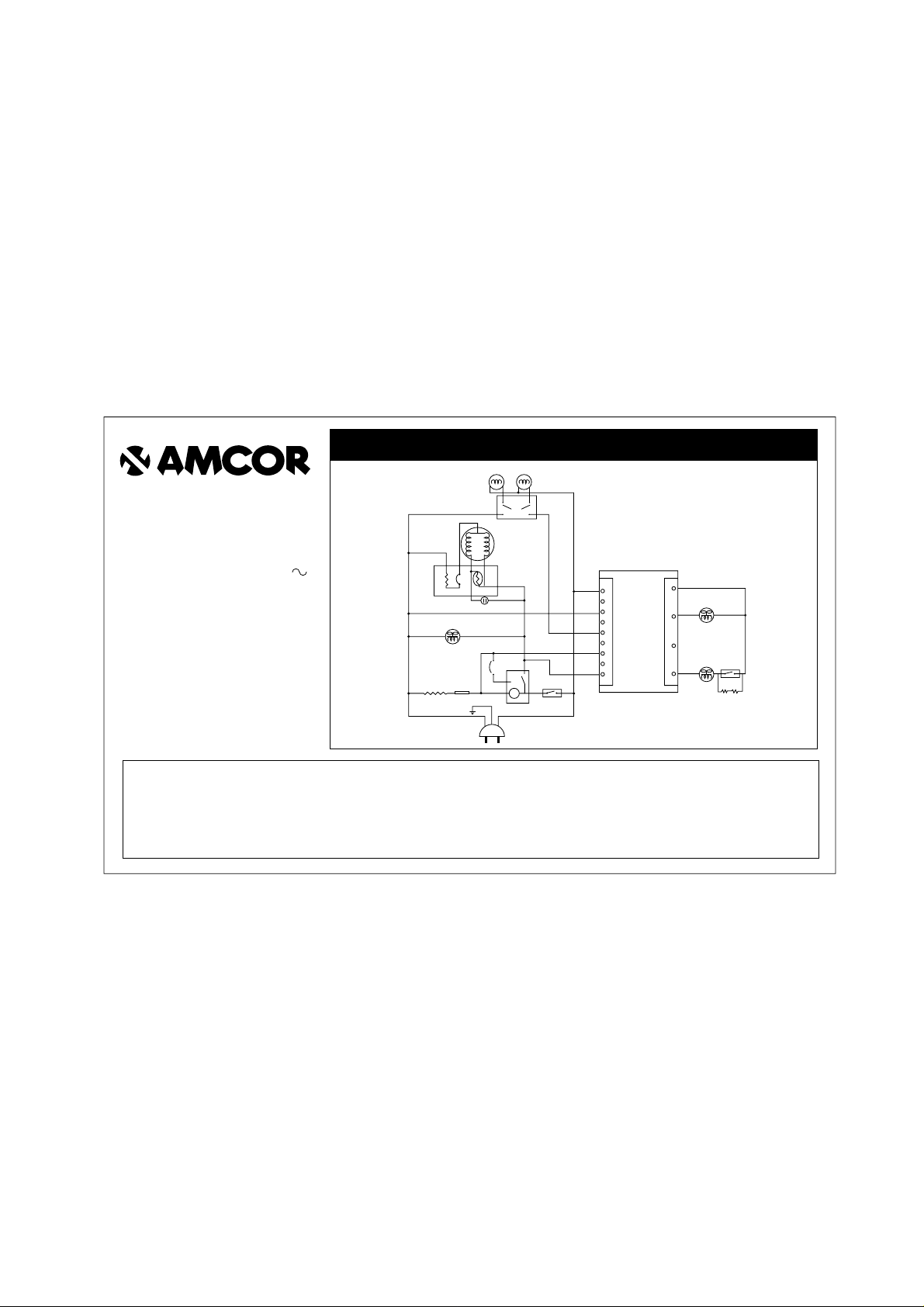
Refrigerator-Freezer
FR-631KD
code:M501-1
WIRING DIAGRAM
3
OL
+0
F-LAMP
DR S/W
COMP
P-RELAY
BI-METAL
2
13
DEFROST
HEATER
TEMP FUSE
77 ¡C
DEFROST TIMER
F-THERMO
YW
GY
RD
BR
AC
M-PCB
DC
9
8
7
6
5
4
2
1
4
3
2
1
BK
WH
(AC INPUT)
(11V)
(F-FAN)
(R-FAN)
R-FAN
R-THERMO
HEATER
R-THERMO
C-FAN
BL
BR
(COMM)
(DFR-1)
(DOOR)
(DFR-4)
POWER CORD
R/C
PTC
24
13
R-LAMP
—4
L/BLUE
BK
GN/YW
WH
BROWN
4
F-FAN
M

Service Manual
Refrigerator
Model: FR-631KD
S/M No. : FR631KD010

1
SAFETY AND PRECAUTIONS
1) For starters, be sure to check any chances of the leakage of electricity
2) You could handle a part in the vicinity of electricity after unplugging
3) You should put on rubber glovers to prevent an electric shock on operation test
4) Make sure the rated current, voltage, capacity before using an instrument
5) Keep your wet hands away from the metal goods in the freezer compartment not to be frostbitten
6) Be careful not to let water to permeate the electric part in the machine room
7) with the door open during your working, you might be damaged by that door
8) You should give a tilt to the refrigerator for your safe after removing the breakable goods inside the refrigerator
9) You'd better use cotton gloves if you fix it up around the evaporator
T ABLE OF CONTENTS
1. EXTERNAL VIEWS
.........................................................................................................................................................
2
1-1. EXTERNAL SIZE
...........................................................................................................................................
2
1-2. NAME OF PARTS
..........................................................................................................................................
2
2. SPECIFICATIONS
...........................................................................................................................................................
3
2-1. OUTLINE
........................................................................................................................................................
3
3. OPERATION AND FUCTIONS
........................................................................................................................................
4
3-1. FUNCTION LIST
............................................................................................................................................
4
3-2. CIRCUIT & WIRE DIAGRAM
.........................................................................................................................
7
3-3. CIRCUIT
.........................................................................................................................................................
8
4. DIAGRAM
......................................................................................................................................................................
14
4-1. AIR FIOW DIAGRAM
...................................................................................................................................
14
4-2. REFRIGENT CYCLE DIAGRAM
..................................................................................................................
15
5. EXPLODED VIEW AND PARTS LIST
...........................................................................................................................
16
5-1. TOTAL EXPLODED VIEW
...........................................................................................................................
16
5-2. TOTAL PARTS LIST....................................................................................................................................17
5-3. MACHINE ROOM EXPLODED VIEW AND PARTS LIST............................................................................21
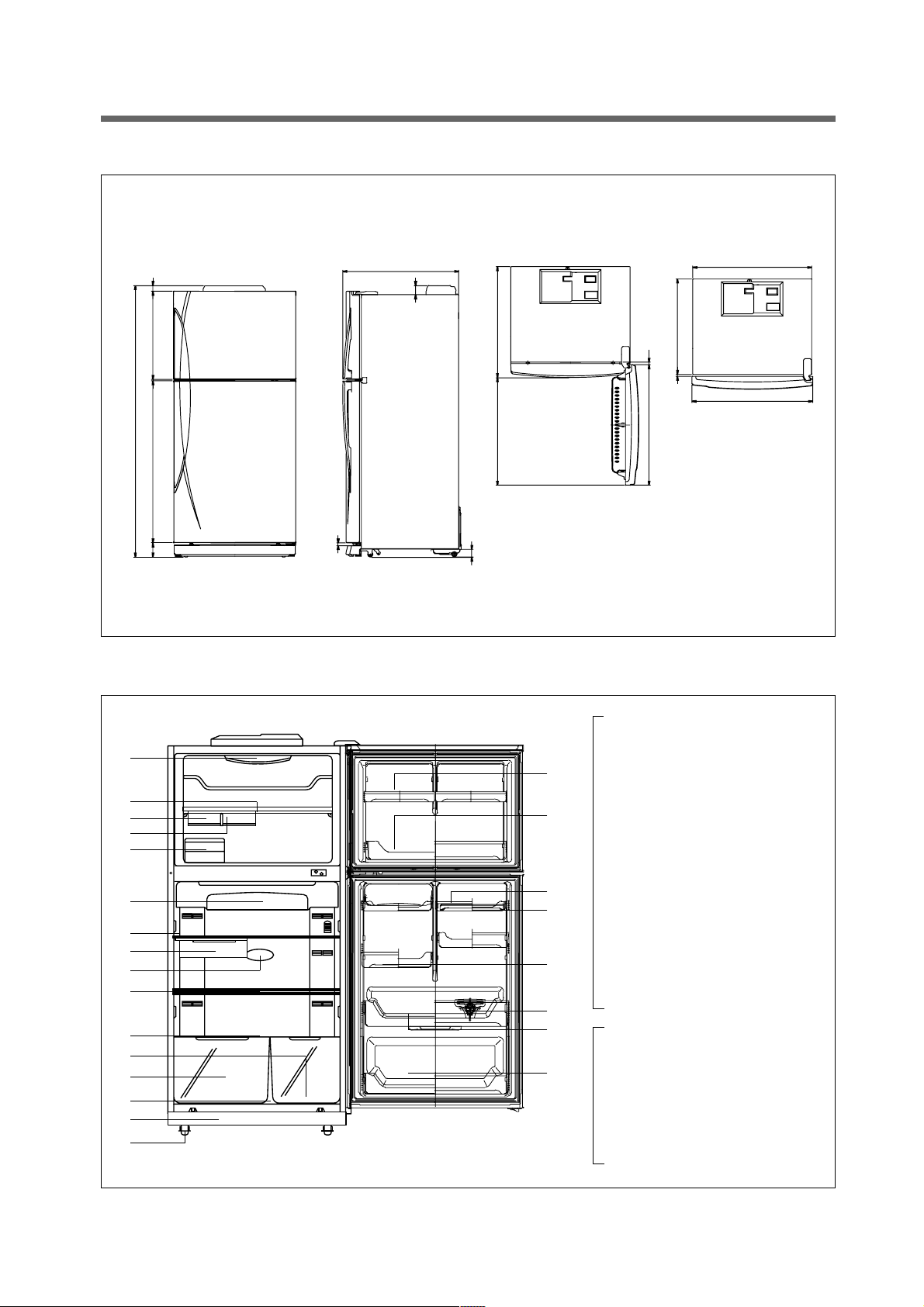
2
1. EXTERNAL VIEWS
1-1. EXTERNAL SIZE
1-2. NAME OF PARTS
1 Freezer Compartment Lamp
2 Shelf Ffreezer
3 Case Icing
4 Guide Icing
5 Ice Box
6 Refrigerator Compartment Lamp
7 Cover Cubic Duct
8 Fresh Case
9 Shelf Refrigerator
0 Deodorant
q Cover Vegetable
w Case Vegetable(B)
e Case Vegetable(A)
r Guide Vegetable
t Front Grille
y Adjustable Foot
u Freezer Pocket Top
i Freezer Pocket Under
o Egg Pocket
p Egg Tray
a Guide Bottle
s Bottle Pocket
d Multi Pocket
f Multi Pocket
38.4
5891084
1817.4
18
62
715.1
96
10
1.1
52
695732
820
17.3
590
12
820
810
u
1
2
3
4
5
6
7
8
9
0
q
w
e
r
t
y
i
p
d
a
s
f
o
3
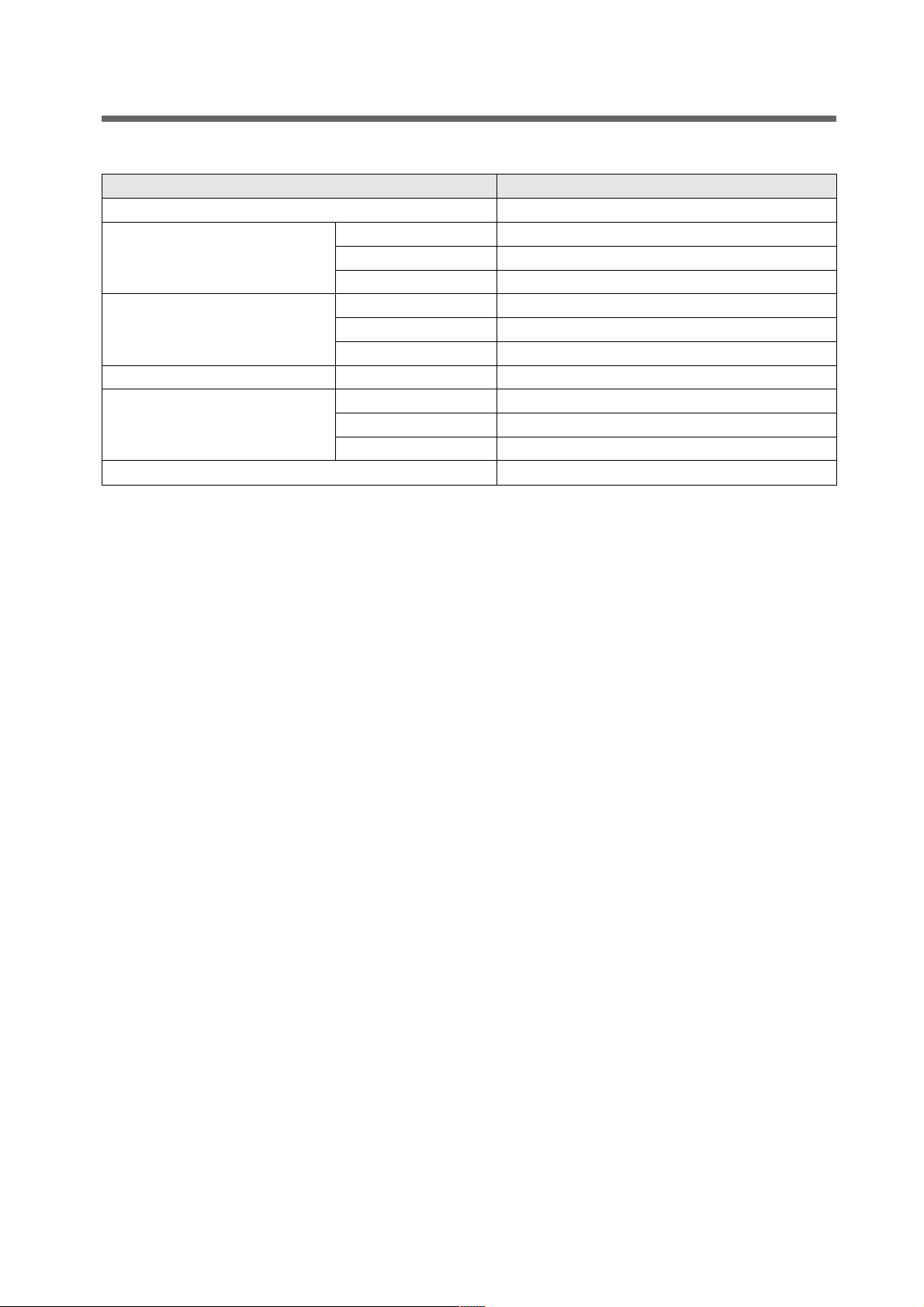
DIVISION CONTENTS
MODEL NAME FR-631KD
FREEZER 138
USABLE CAPACITY (L) REFRIGERATOR 366
TOTAL 504
WIDTH 818
EXTERNAL DIMENSION( mm) DEPTH 752
HEIGHT 1818
REFRIGENT R134a 110
COOLING SYSTEM Fan Cooling System
COOLING &CONTROL SYSTEM DEFROST SYSTEM Fin Evaporator Forced
DEFORST CONTROL Automatic Start & Stop
NET WEIGHT (kg) 85
2. SPECIFICATIONS
2-1. OUTLINE
4
3. OPERATION AND FUCTIONS
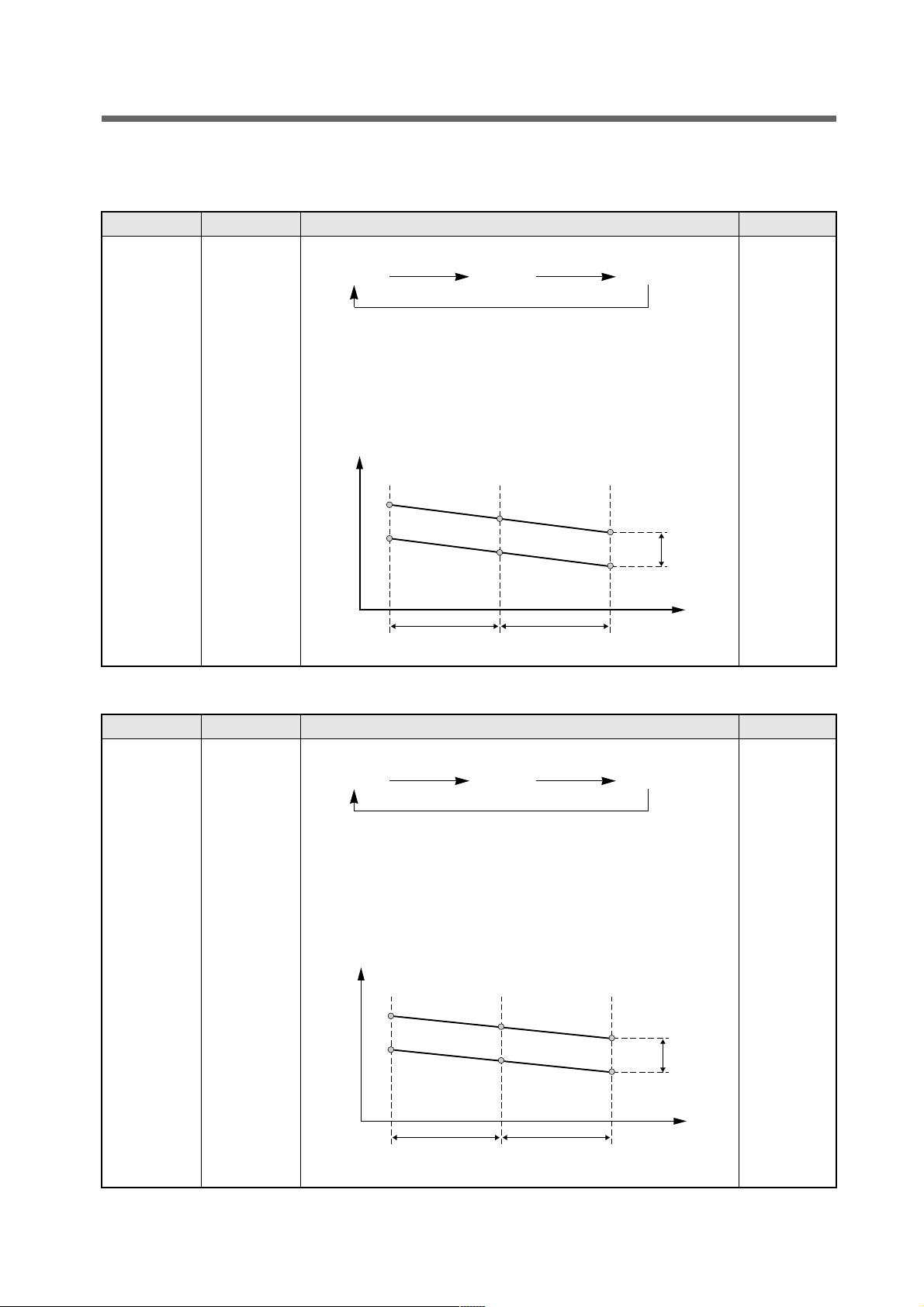
3-1. Function List
1-1. Freezer T emperature
Input Control Object Contents Remark
1. Temperature
Dial
2. F Thermostat
3. ON / OFF
DIFF.
1. COMP
2. F-FAN
3. C-FAN
1. Freezer temperature is controlled by Freezer Temperature Dial.
Weak Middle Strong
2. COMP, F-FAN and C-FAN are controlled by ON/OFF point of each
mode.
3. ON / OFF DIFF of Freezer : 4.0°C
(Middle OFF Point of Freezer : -12.0°C)
4. Strong / Weak Step DIFF of Freezer : 3.0°C
5.
Weak Middle
STEP DIFF
-13.0˚C
-9.0˚C
-16.0˚C
-12.0˚C
-19.0˚C
OFF
ON
-15.0˚C
Strong
Temperature
MODE
STEP DIFF
ON/OFF
DIFF
Input Control Object Contents Remark
1. Temperature
Dial
2. R Thermostat
3. ON / OFF
DIFF
1. R-Fan 1. efrigerator temperature mode is set by the temperature dial.
Weak Middle Strong
2. R-FAN is controlled by ON / OFF point of each mode.
3. ON / OFF DIFF of Refrigerator : 3.0°C
(Middle OFF Point : 0.5°C)
Strong / Weak STEP DIFF : 2°C
* When R-Thermo reaches to R-FAN ON point, R-FAN turns ON ;
OFF point, R-FAN turns OFF.
Weak Middle
STEP DIFF
2.5˚C
5.5˚C
0.5˚C
3.5˚C
-1.5˚C
OFF
ON
1.5˚C
Strong
Temperature
MODE
STEP DIFF
ON/OFF
DIFF
1-2. Refrigerator(Fresh Food Compartment) T emperature
5
Input Control Object Contents Remark
1. Accumulated
work time of
COMP
1. Defrosting
Mode
1. What to consider in determining the defrosting cycle
☞ Total (accumulated) work time of COMP
2. Conditions to start defrosting mode
☞ When total work time of COMP is more than 8, defrosting mode
starts unconditionally.
1-3. Defrosting Cycle
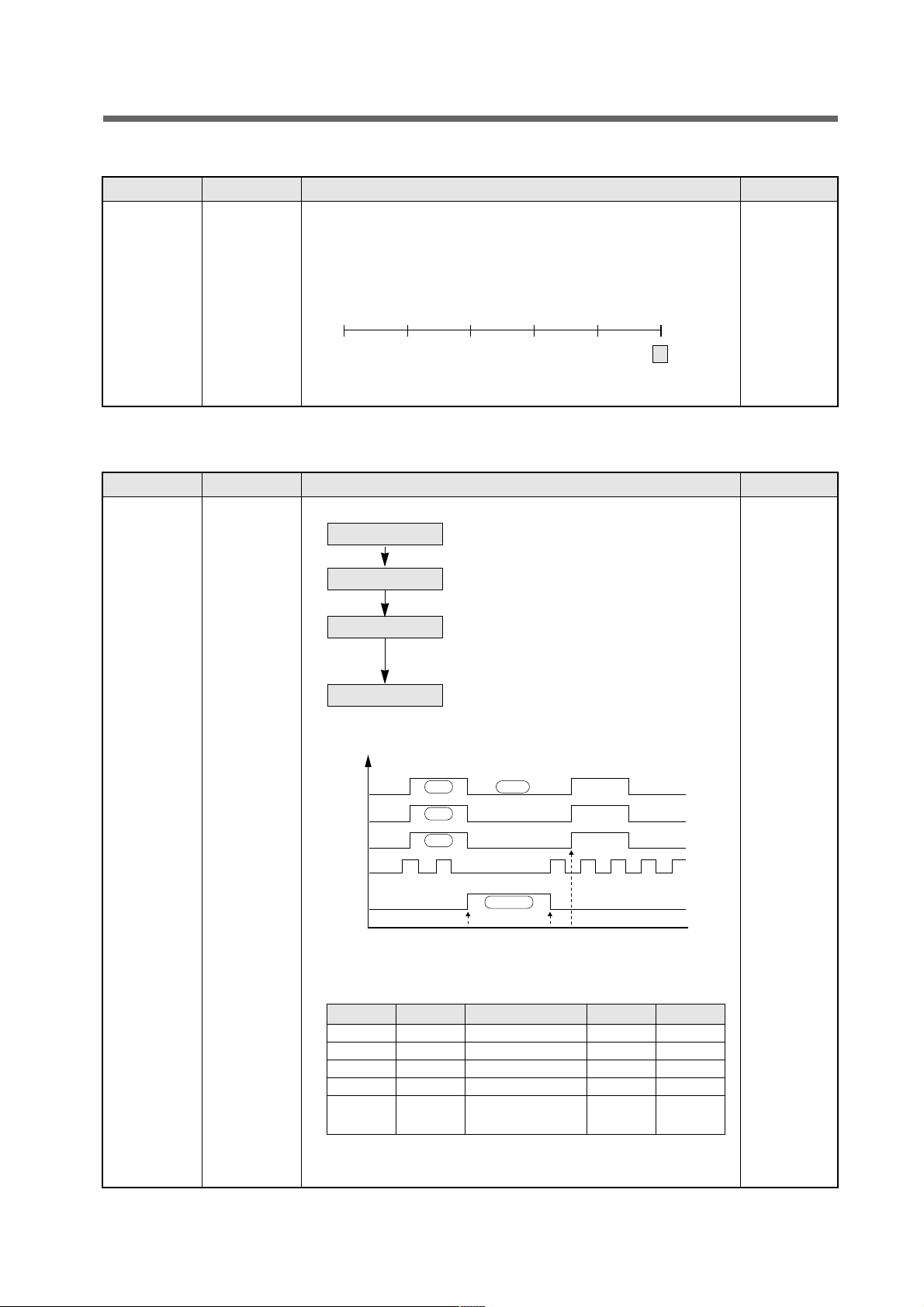
START 2 4 6 7
(Total Work Time of COMP)
8
Input Control Object Contents Remark
1.Defrosting
Cycle
1. COMP
2. F-FAN
3. R-FAN
4. HEATER
1. Defrosting Mode
1) COMP, F/R/C-FAN: Control
1) If Bi-Metal is over 10, Heater turns Off.
2) COMP, F/R/C FAN: Off
1) Pause: 5 minutes
2) COMP, F/C-FAN: Off
3) R FAN: Control
1) COMP, F/R/C FAN: Control
2. Time Chart in Defrosting Mode
3. Output Control & Limit Time of Each Defrosting Mode
1) When defrosting starts COMP and F/R/C-FAN turn Off.
2) R Fan is ON/OFF Controlled in Pause mode.
1-4. Defrosting Mode
Control
Heater Defrosting
Pause
Control
Control Heate Defrosting Pause Control
COMP ON/OFF OFF OFF ON/OFF
F-FAN ON/OFF OFF OFF ON/OFF
R-FAN ON/OFF OFF ON ON/OFF
HEATER OFF ON OFF OFF
Limit Time – If Bi-metal≥10°C, 5min. –
HTR turns Off.
Comp
F-FAN
C-FAN
R-FAN
HTR
ON OFF
ON
ON
HTR ON
HTR Start HTR Finish
Pause Star
Pause Finish/
CONTROL
 Loading...