

Daewoo FR-551NT, Fr-521nt Service Manual
S/M No. : FR521NT010
Service Manual
Refrigerator
Model :
FR-521NT/551NT
FR-521NB/551NB
DAEWOO ELECTRONICS CO., LTD
http : //svc.dwe.co.kr
Nov. 1999

SAFETY AND PRECAUTIONS
1) For starters, be sure to check any chances of the leakage of electricity.
2) You could handle a part in the vicinity of electricity after unplugging.
3) You should put on rubber glovers to prevent an electric shock on operation test.
4) Make sure the rated current, voltage, capacity before using an instrument.
5) Keep your wet hands away from the metal goods in the freezer compartment not to be frostbitten.
6) Be careful not to let water to permeate the electric part in the machine room.
7) With the door open during your working, you might be damaged by that door.
8) You should give a title to the refrigerator for your safe after removing the breakable goods inside the refrigerator.
9) You'd better use cotton gloves if you fix it up around the evaporator.
TABLE OF CONTENTS
EXTERNAL VIEWS .......................................................................................................................... 2
1. EXTERNAL SIZE .......................................................................................................................... 2
2. NAME OF PARTS ........................................................................................................................ 3
SPECIFICATIONS ............................................................................................................................ 4
1. OUTLINE ...................................................................................................................................... 4
2. ELECTRIC PARTS ....................................................................................................................... 4
3. POWER CORD ............................................................................................................................ 8
4. DOOR COLOR ............................................................................................................................. 9
OPERATION AND FUNCTIONS .............................................................................................. 10
DIAGRAM ......................................................................................................................................... 15
1. WIRING DIAGRAM ...................................................................................................................... 15
2. CIRCUIT WIRING DIAGRAM ....................................................................................................... 16
3. AIR FLOW DIAGRAM .................................................................................................................. 17
4. REFRIGRANT CYCLE DIAGRAM ............................................................................................... 18
DISASSEMBLY AND ASSEMBLY .................................................................................................. 19
EXPLODED VIEW AND PARTS LIST.............................................................................................. 31
1. TOTAL EXPLODED VIEW............................................................................................................ 31
2. TOTAL PARTS LIST..................................................................................................................... 32
3. MACHINE ROOM EXPLODED VIEW AND PARTS LIST............................................................. 36
1
EXTERNAL VIEWS
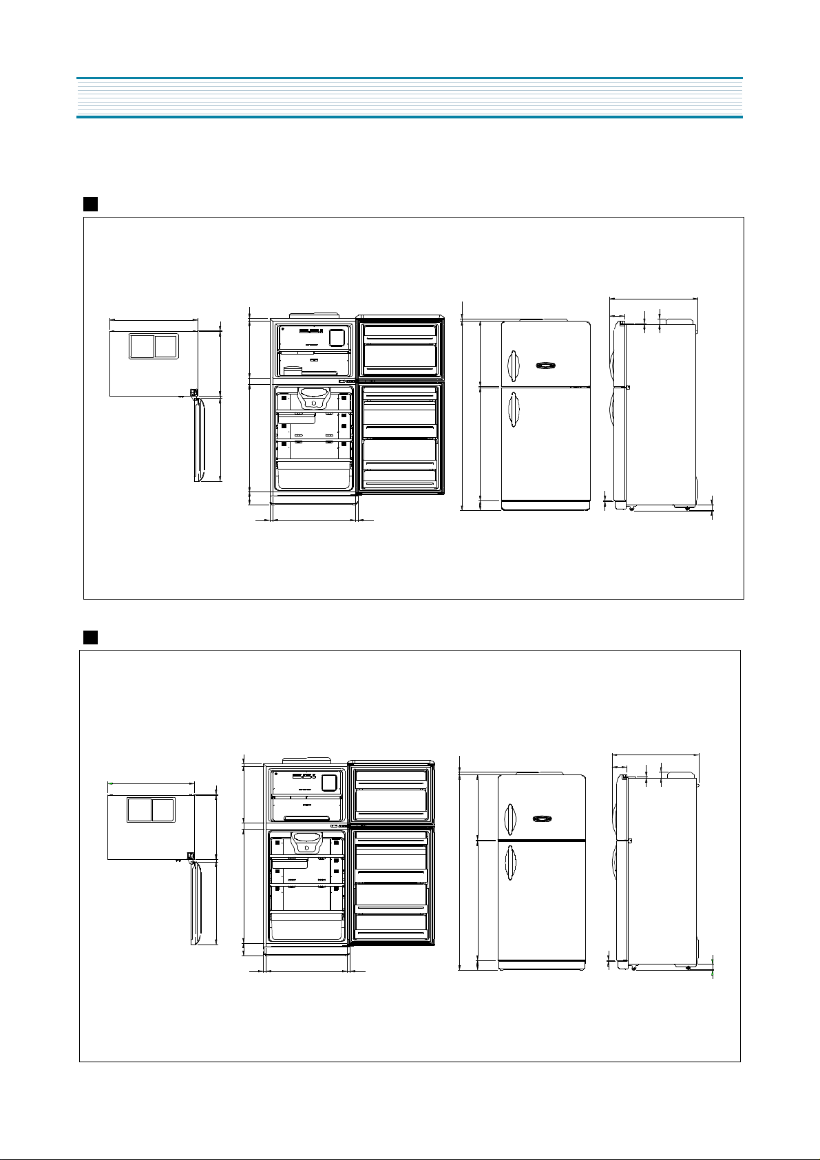
1. EXTERNAL SIZE
FR-521NT/NB
750
24
20
750
126
11
20.5
53
FR-551NT/NB
750
518
590
60
19
978
757
114
24 24
24
20
518
60
590
19
1038
757
702
597
10
1728. 5
1028. 5
93
20.5
597
10
1788.5
15
750
126
11
53
53
3.5
114
702
24
24
93 1088.5
15
53
3.5
2
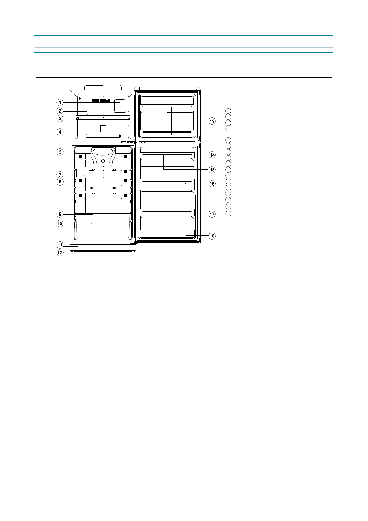
2. NAME OF PARTS
EXTERNAL VIEWS
1
Freezer Compartment Lamp
2
Shell Freezer & Icr Tray
3
Case Icing
4
Temperature Controller
( Freezer Compartment )
5
Refrigerator Compartment Lamp
7
Fresh Case
8
Shell Refrigerator
9
Cover Vegetable
10
Case Vegetable
11
Front Grille
12
Adjustable Foot
13
Freezer Pocket
14
Egg Pocket
15
Egg Tray
16
Bottle Pocket
17
Multi Pocket
18
Multi Pocket
3
SPECIFICATIONS
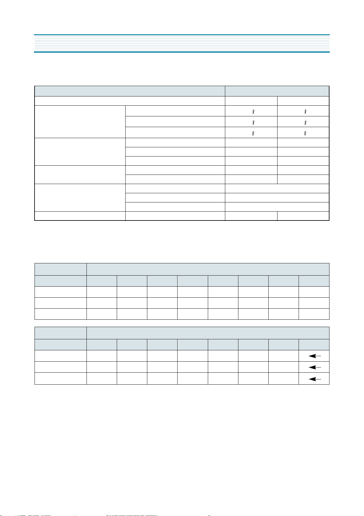
1. OUTLINE
DIVISION CONTENTS
MODEL NAME FR-521NT FR-551NT
USABLE CAPACITY FREEZER
REFRIGERATOR
TOTAL
EXTERNAL DIMENSION WIDTH 757mm 757mm
DEPTH 750mm 750mm
HEIGHT 1749mm 1809mm
REFRIGENT R12 160g 160g
R134a 130g 130g
COOLING & CONTROL SYSTEM COOLING SYSTEM Fan Cooling System
DEFROST SYSTEM Fin Evaporator Forced
DEFORST CONTROL Automatic Start & Stop
NET WEIGHT 71kg 72kg
125 125
319 355
444 480
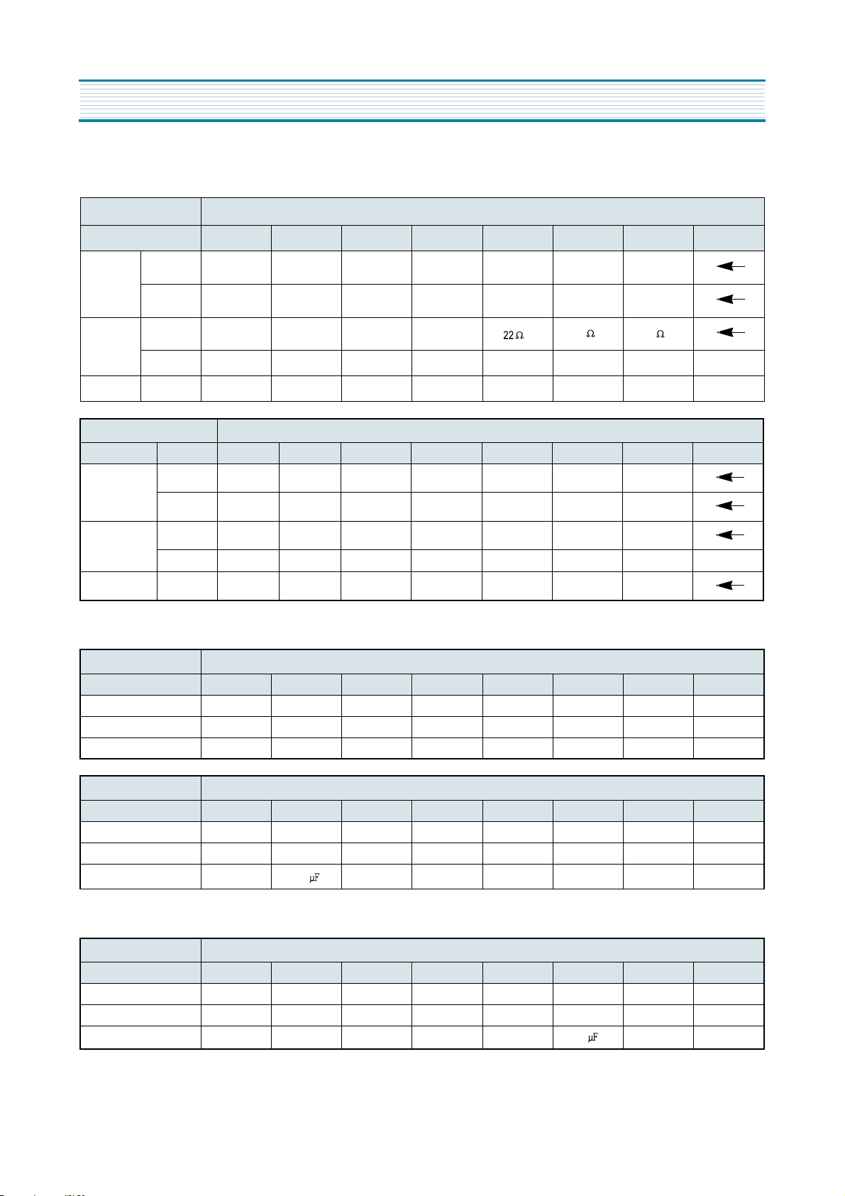
2. ELECTRIC PARTS
1) COMPRESSOR
REFRIGEANT R12
VOLTAGE(V/HZ) 100/50,60 110/60 115,120/60 127/60 220/50 220/60 230/50 240/50
COMP MODEL X X X X SL28YE-5 PL23YH-4 SL28YE-5 SL28YE-5
PART CODE X X X X 3954128A50 3956123P40 3954128A50 3954128A50
STARING TYPE X X X X RSIR RSCR RSIR RSIR
REFRIGEANT R134a
VOLTAGE(V/HZ) 100/50,60 110/60 115,120/60 127/60 220/50 220/60 230/50 240/50
COMP MODEL X HBL25YG-3 X X HPL26YH-5 X HPL26YH-5
PART CODE X 3952125R30 X X 3956126S50 X 3956126S50
STARING TYPE X CSR X X RSCR X RSCR
4
SPECIFICATIONS
2) RELAY
REFRIGEANT R12
VOLTAGE(V/HZ) 100/50,60 110/60 115,120/60 127/60 220/50 220/60 230/50 240/50
ASSY
PTC RESIANCE X X X X
OVER LOAD
TYPENAME
PART CODE
PART CODE
OVER LOAD X
X X X X
X X X X
X X X X
X X X
276THBYY-52 181SHBYY-52 276THBYY-52
3018119940 3018116610 3018119940
33 22
REFRIGERANT R134a
VOLTAGE(V/HZ) 100/50,60
ASSY TYPE NAME
PART CODE X 3018119390
PTC RESISTANCE
PART CODE
OVER LOAD PART CODE
X
X S220 X X S330 X S330
X X X X X
X 783NHB X X 197NHB X 197NHB
110/60 115,120/60
783NHBZZ-52
X X
X
127/60 220/50 220/60 230/50 240/50
197NHBYY-52 X 197NHBYY-52
X 3018119920 X 3018119920
3) STARTING CAPACITOR
REFRIGERANT R12
VOLTAGE(V/HZ) 100/50,60 110/60 115,120/60 127/60 220/50 220/60 230/50 240/50
PART CODE X
RATED VOLTAE X X X X X X X X
RATED CAPACITANCE X X X X X X X X
X
X X X X X X
REFRIGERANT R134a
VOLTAGE(V/HZ) 100/50,60 110/60 115,120/60 127/60 220/50 220/60 230/50 240/50
PART CODE X 3016400100 X X X X X X
RATED VOLTAE X 100V X X X X X X
RATED CAPACITANCE X
100
X X X X X X
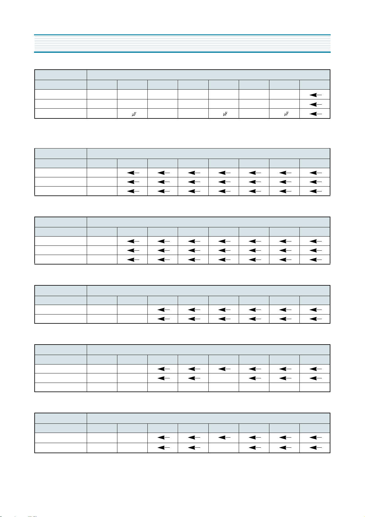
4) RUNNING CAPACITOR
REFRIGERANT R12
VOLTAGE(V/HZ) 100/50,60 110/60 115,120/60 127/60 220/50 220/60 230/50 240/50
PART CODE X
RATED VOLTAE X X X X X 350V X X
RATED CAPACITANCE X X X X X
X
X X X 400EL15110 X X
5
5
X X
SPECIFICATIONS
REFRIGERANT R134a
VOLTAGE(V/HZ) 100/50,60 110/60 115,120/60 127/60 220/50 220/60 230/50 240/50
PART CODE
RATED VOLTAE X 300V X X 400V X 400V
RATED CAPACITANCE X
X 3816800400
7
X
X X
X
3016401900
4
X
X
3016401900
4
5) F-FAN MOTER
REFRIGERANT R12,R134a
VOLTAGE(V/HZ) 100/50,60 110/60 115,120/60 127/60 220/50 220/60 230/50 240/50
TYPE NAME
PART CODE 3015907200
REVOLUTION 2200RPM
DL-2213DWFC
6) C-FAN MOTER
REFRIGERANT R12,R134a
VOLTAGE(V/HZ) 100/50,60 110/60 115,120/60 127/60 220/50 220/60 230/50 240/50
TYPE NAME
PART CODE 3015907300
REVOLUTION 2200RPM
DL-2213DWCB
7) DEFROST HEATER
REFRIGERANT R12,R134a
VOLTAGE(V/HZ) 100/50,60 110/60 115,120/60 127/60 220/50 220/60 230/50 240/50
SPEC(W)
PART CODE X 3012805500
X
148W
8) LAMP ASSEMBLY
REFRIGERANT R12,R134a
VOLTAGE(V/HZ) 100/50,60 110/60 115,120/60 127/60 220/50 220/60 230/50 240/50
SPEC(W)
PART CODE X 301360010 3013600080
COLOR
X 15W
9) PCB TRANSFORMER
REFRIGERANT R12,R134a
VOLTAGE(V/HZ) 100/50,60 110/60 115,120/60 127/60 220/50 220/60 230/50 240/50
TYPE NAME
PART CODE X 5EPK057860 5EPK057004
X FRB-5070NT
6
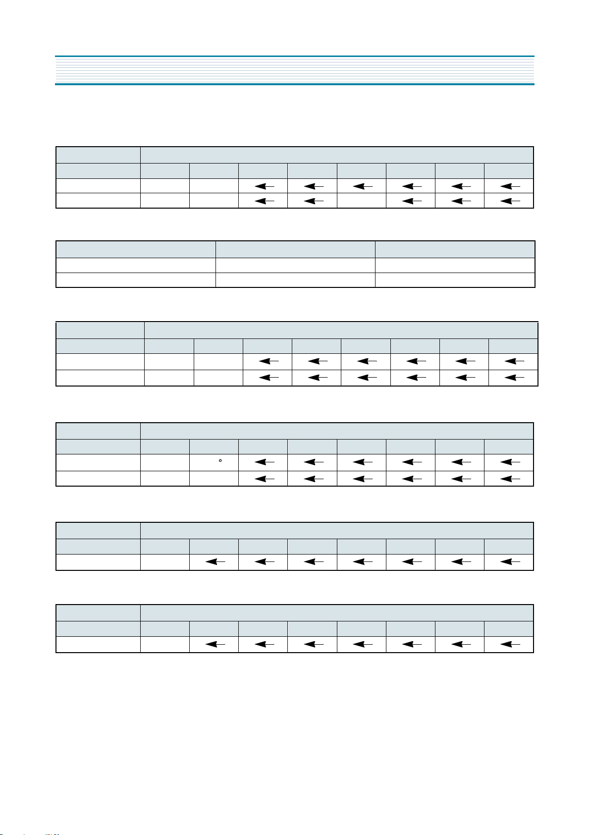
SPECIFICATIONS
10) MAIN PCB ASSEMBLY
REFRIGERANT R12,R134a
VOLTAGE(V/HZ) 100/50,60 110/60 115,120/60 127/60 220/50 220/60 230/50 240/50
TYPE NAME
PART CODE X 3014385070 3014385060
X
N808RT
11) DRYER
REFRIGERANT R12 R134a
SPEC (g) 10g 15g
PART CODE 3016801000 3016801010
12) FUSE (PCB)
REFRIGERANT R12,R134a
VOLTAGE(V/HZ) 100/50,60 110/60 115,120/60 127/60 220/50 220/60 230/50 240/50
RATED CURRENT
PART CODE X 5F3GB1682R
X 250V/1.6A
13) THERMO FUSE
REFRIGERANT R12,R134a
VOLTAGE(V/HZ) 100/50,60 110/60 115,120/60 127/60 220/50 220/60 230/50 240/50
OPERATING TEMPERATURE
PART CODE X 3017200500
X
C
77
14) DOOR S/W
REFRIGERANT R12,R134a
VOLTAGE(V/HZ) 100/50,60 110/60 115,120/60 127/60 220/50 220/60 230/50 240/50
PART CODE 3018100010
15) R-SENSER
REFRIGERANT R12,R134a
VOLTAGE(V/HZ) 100/50,60 110/60 115,120/60 127/60 220/50 220/60 230/50 240/50
PART CODE 301482300
7
SPECIFICATIONS
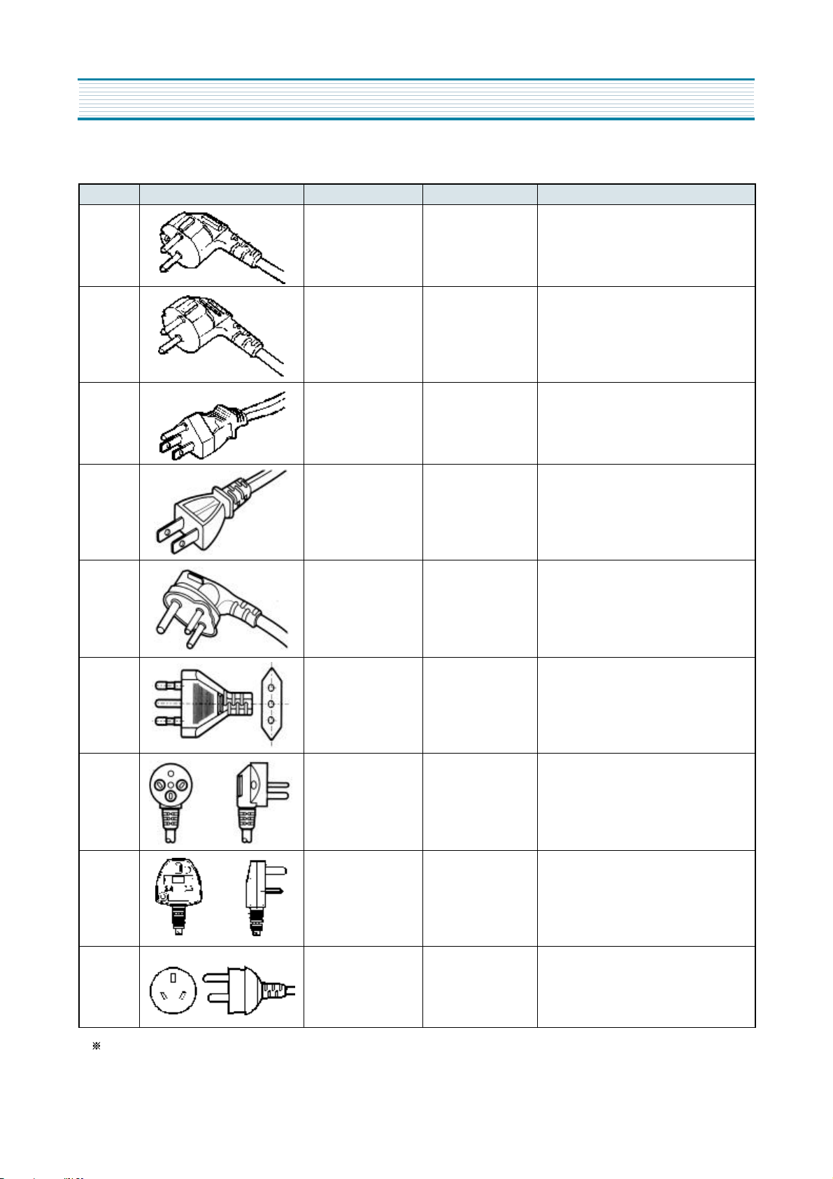
3. POWER CORD
NO SHAPE OF CODE PART CODE DESCRIPTION REMARK
1 3011315000 CP-2PIN FOR EUROPEAN COUNTRY
2 401RA17200 CP-2PIN FOR OTHER COUNTRY
3 4006D17101 KP-30 FOR AMERICA & ELSALVADOR
4 401PD17101 KP-211 FOR JAPAN & TAIWAN
5 3011300801 BP-3PIN
6 3011303010 #267 FOR CHILE
7
8
3011315310 FOR ISRAEL
3011303050 BS-1363A
FOR U.K, MIDDLE ASIA
SINGAPORE & MALAYSIA
9 3011301200 KP551/550 FOR CHINA & AUSTRALIA
Upper power cord’ s part code is only for lead wire, without any kinds of terminal or housing
8
SPECIFICATIONS
4. DOOR COLOR
1) ASSEMBLY URETHAN FREEZER DOOR
REFRIGERANT
COLOR TYPE
PART CODE X 3010075150 X X X 3010075170 X X
Dull
lamina sheet
High-glossy
Lamina sheet
2) ASSEMBLY URENTHAN REFRIGERATOR DOOR
FR-521NT
NON-KEY TYPE
R12 R134a
Normal PCM
High-glossy
Bright PCM
Dull
lamina sheet
High-glossy
Lamina sheet
Normal PCM
High-glossy
Bright PCM
REFRIGERANT
COLOR TYPE
PART CODE X 3010079100 X X X 3010079140 X X
Dull
lamina sheet
High-glossy
Lamina sheet
R12 R134a
Normal PCM
High-glossy
Bright PCM
Dull
lamina sheet
High-glossy
Lamina sheet
Normal PCM
High-glossy
Bright PCM
KEY TYPE
REFRIGERANT
COLOR TYPE
PART CODE X 3010079150 X X X 3010079160 X X
FR-551NT
Dull
lamina sheet
High-glossy
Lamina sheet
R12 R134a
Normal PCM
High-glossy
Bright PCM
Dull
lamina sheet
High-glossy
Lamina sheet
Normal PCM
High-glossy
Bright PCM
NON-KEY TYPE
REFRIGERANT
COLOR TYPE
PART CODE X 3010079110 X X X 3010079130 X X
Dull
lamina sheet
High-glossy
Lamina sheet
R12 R134a
Normal PCM
High-glossy
Bright PCM
Dull
lamina sheet
High-glossy
Lamina sheet
Normal PCM
High-glossy
Bright PCM
KEY TYPE
REFRIGERANT
COLOR TYPE
PART CODE X 3010079170 X X X 3010079180 X X
Dull
lamina sheet
High-glossy
Lamina sheet
R12 R134a
Normal PCM
High-glossy
Bright PCM
9
Dull
lamina sheet
High-glossy
Lamina sheet
Normal PCM
High-glossy
Bright PCM
OPERATION AND FUNCTIONS
CONTROL
NO
FUNCTION
1 Display F-PCB
2 Temperature
Regulation of
Freezer
Compartment
INPUT CONTROL
Button :TEMP
CONTROL Button
1. TEMP Conrol
Button
2. R-Sensor
3. RT-Sensor
OBJECTS
Custom LED
COMP F-FAN
CONTENTS REMARK
1. Normal State
Initial State ; Both compartments’ Icons indicate Middle-mode
(“ 1” , and “ 2” are lit.)
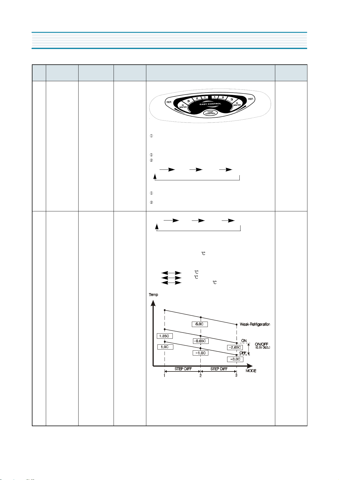
2. TEMP CONTROL Button
Temperature Regulation of Freshfood Compartment
Middle-right Icons are lit by pressing the button.
(1) 2 3 In winter
3. Temperature Regulation of Freezer Compartment
Temperature is regulation by moving the lever to the left and / or the
right.
Temperature has nothing to do with PCB control.
1. Temperature regulation by TEMP Control Button.
(1) 2 3 In winter
2. R-Fan is controlled by On/Off-point of each mode.
3. On/Off DIFF : 1.0
( Middle (“ 1” ) OFF-point : 4.0 )
4. Step Difference of Fresh Food Compartment.
* 1 2 : 1.0
* 2 3 :1.0
* 3 IN WINTER : 1.0
Reference
- ON/OFF Diff :
Fixed at
Micom
- STEP Diff :
Fixed at
Micom
Comp and
C-fan are
Coworking
10
OPERATION AND FUNCTIONS
CONTROL
NO
FUNCTION
3 Defrosting
Period
4 Defrosting
Mode
INPUT CONTROL
OBJECTS
1. Total Run-time
of COMP
2. Running-rate of
COMP
3. Total time of
Door openings
4. RT Temperature
Defrosting Period 1. COMP
Defrosting
Mode
2. R-FAN
3. HEATER
CONTENTS REMARK
1. What to be considered in determing Defrosting Period
1) Total Run-time of COMP : 6, 8, 10, 12, 14 hours
2) Running-rate of COMP (each 2hours’ running-rate) :
more than 80%
3) Total time of Door openings : 10 minutes
4) Total Time (COMP-On + COMP Off ) : 60 hours
5) Ambient Temperature : more than 35
6) In each Error : R1, F1, D1, F3, RT-S, Door-SW Error
2. Terms to start Defrosting Period
1) The Defrosting starts with the following conditions, in
case total COMP-run time passes 6, 8, 10 or 12hours
- when an Error occurs
- when running-rate of COMP is more than 80%
- when total Door-opening time is more than 10minutes
- when the ambient temperature is more than 35
2) Defrosting starts unconditionally when total COMP-
run time passes 14 hours, under the condition taht
terms of 1) are not satisfied.
3) Defrosting starts immediately when Total-time
(COMP-On + Off time) is more than 60 hours, under
the condition that terms of 1) and/or 2) are not satis
fied.
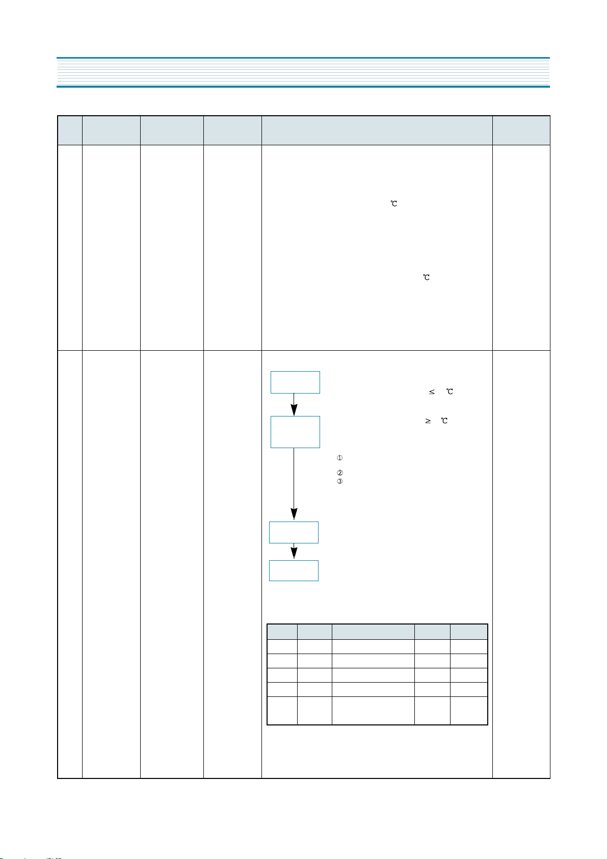
1.Defrosting Mode
Pre-Cool
1) Time : 25minutes
2) COMP and R-Fan are On, and HTR is off
3) Pre-cool turns off when R-Sensor 2.5
C-Fan and
COMP are coworking.
Heater
Defrosting
Pause
Fan Delay
1) Heater turns off when D-Sensor 10
2) Limit time : 80minutes
3) Heater continues to be On for 40 minutes of limit time
when D-Sensor is in Error
4) Limit time
30seconds : Heater continues to be On after
Defrosting regardless of D-Sensor temperature.
40minutes : in case of D1-Error
80minutes : in normal control state
1) Time : 4minutes
2) COMP and R-Fan are Off.
1) Time : 5minutes
2) Only COMP is On, While R-Fan is Off.
2. Output Control and Limit Time of each Defrosting Mode
Pre-Cool Heater Defrosting Pause Fan Delay
COMP ON OFF OFF ON
F-FAN ON OFF OFF OFF
R-FAN
CONTROL
HETER OFF ON OFF OFF
Limit Time 50MINUTES
OFF OFF OFF
(1) 80 MINUTES
(2) 40 MINUTES
in case of D-Sensor Error
4MINUTES 5MINUTES
11
 Loading...