

Daewoo DWD-M1041 Service Manual

Service Manual
Washing Machine
Model:
DWD-M8041/M8042/M8043
DWD-M1041
DWD-M1241/M1242/M1243
S/M No. :
✔ Caution
: In this Manual, some parts can be changed for improving, their per-
formance without notice in the parts list. So, if you need the latest
parts information, please refer to PPL(Parts Price List) in Service
Information Center (http://svc.dwe.co.kr).
DAEWOO ELECTRONICS CORP.
http : //svc.dwe.co.kr Jan. 2010
9
DIRECTION FOR DISASSEMBLY
4. DIRECTION FOR DISASSEMBLY
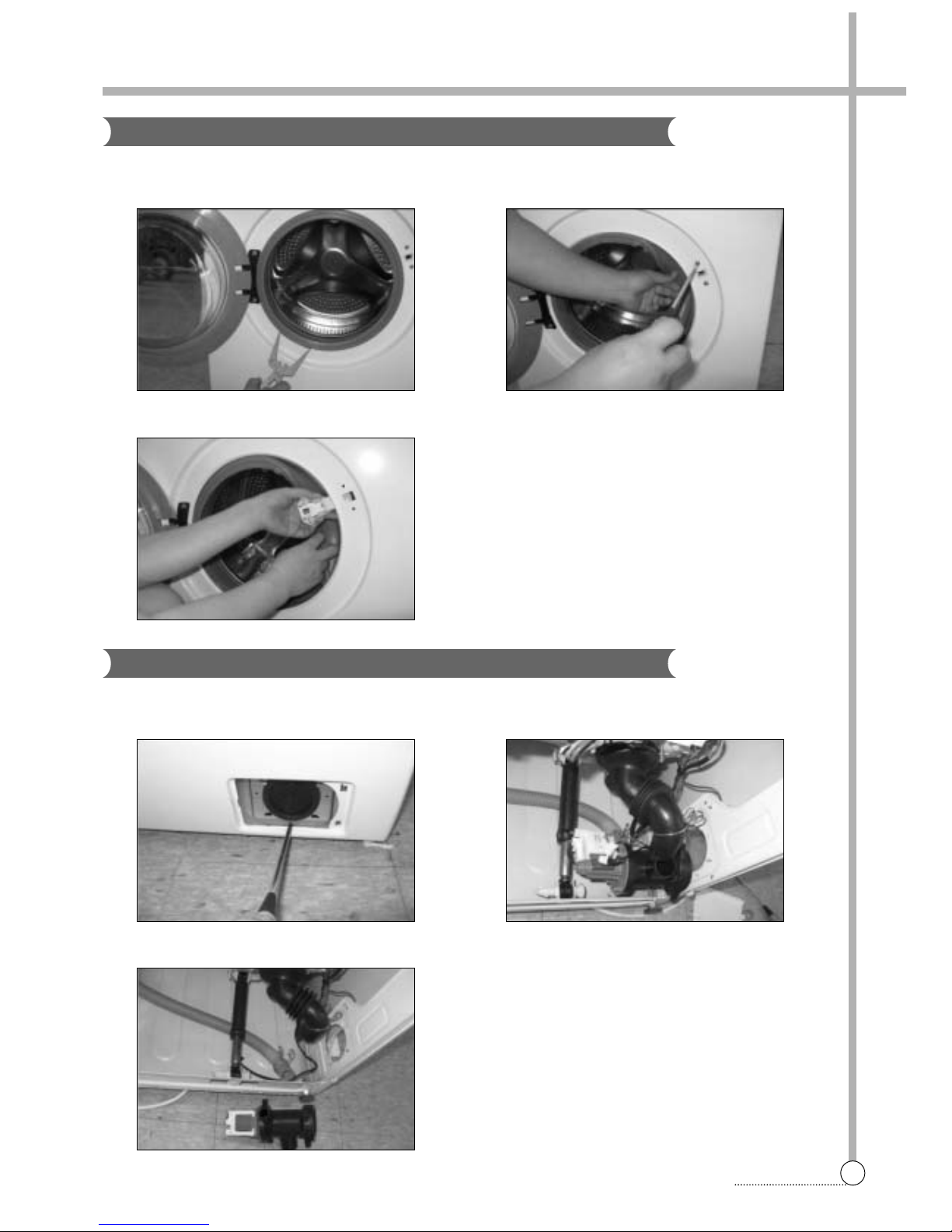
DOOR LOCK SWITCH
1 Open the door and remove the clamp door as. 2 Separate the gasket from the cabinet front and remove
two screws.
DRAIN PUMP
3 Remove the door lock switch from the cabinet front .
1 Separate the cover pump from the cabinet front and
remove screw.
2 Lay the right-side of the washer on the floor. And sepa-
rate connectors and hose drain from the pump.
3 Remove the hose drain o from the pump.
10
DIRECTION FOR DISASSEMBLY
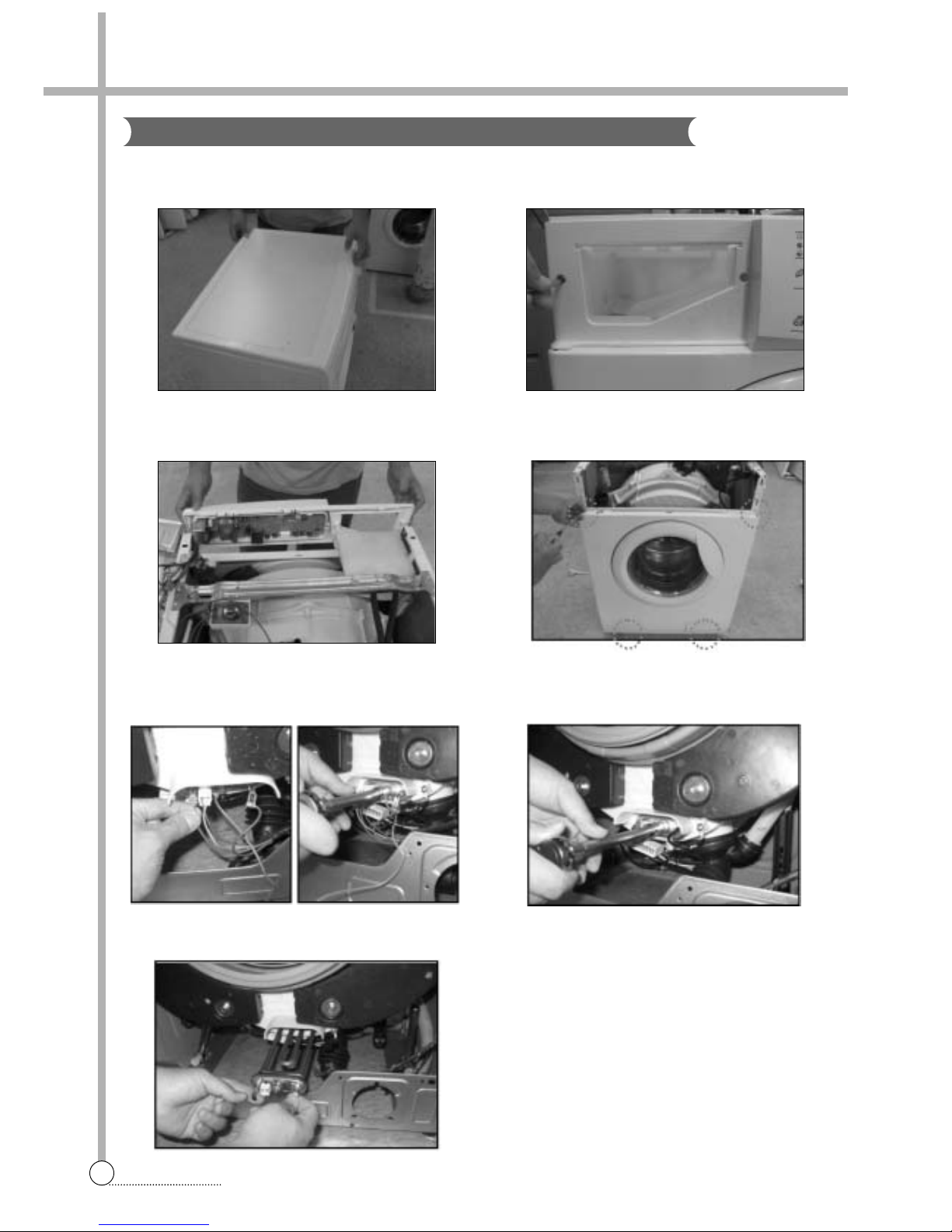
HEATER AND THERMISTOR
1 Separate the plate t as from the washer.
(Remove two screws at rear)
2 Separate the case detergent as and remove two
screws from panel f.
3 Separate the panel f as from the washer. 4 Separate the cabinet front from the washer.
(Remove the clamp door as and 4 screws)
5 Separate connectors from the heater and remove the
nut by using a box wrench.
6 Remove the earth terminal and loosen the nut by using
a box wrench.
7 Pull out the heater from the tub.
11
DIRECTION FOR DISASSEMBLY
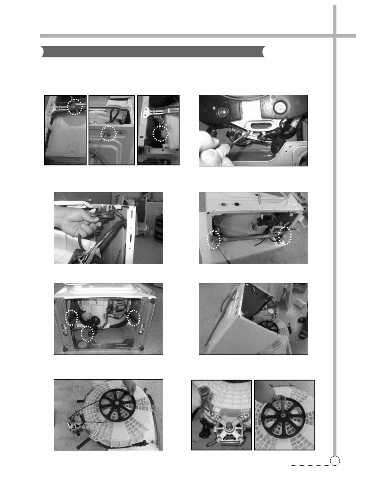
UNIVERSAL MOTOR
1 Separate the box inlet as from the washer.
(Remove screws and hose inlet)
2 Remove the screw of the motor connector.
And separate the connector from the tub.
Firstly, you have to do from 1 to 5 of HEATER AND THERMISTOR DISASSEMBLY.
3 Separate the hose air from the sensor pressure. 4 Lay the front-side of washer on the floor.
And remove four screws.
5 Separate two dampers and the hose drain. 6 Lift up the cabinet as.
7 Separate the belt. 8 Remove two screws from the motor and remove the
screw from the drum using a box wrench.
5. EXPLODE VIEW AND P ARTS LIST
12
EXPLODE VIEW AND PARTS LIST
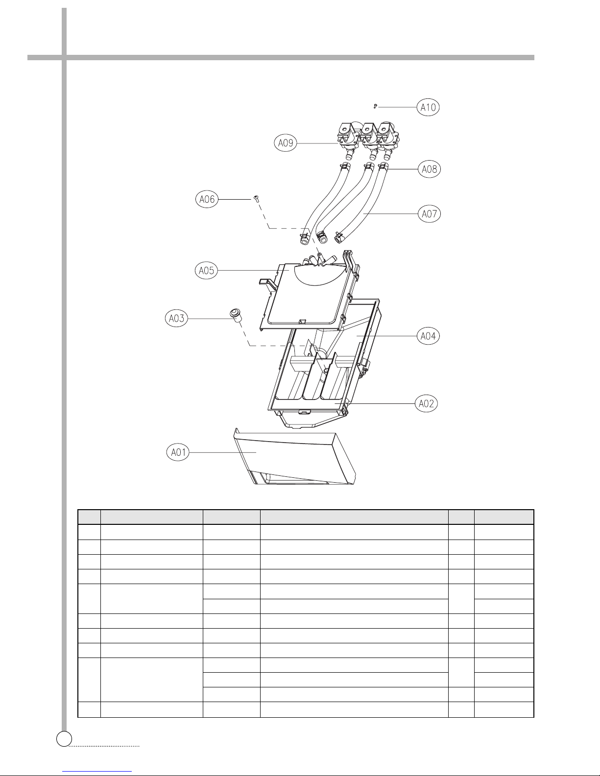
■ BOX INLET AS
A01 CASE HANDLE 36111T1U00 ABS D-MU1041 1
A02 CASE DETERGENT 3611145800 PP 1
A03 CAP SOFTENER 3610907800 PP 1
A04 BOX INLET 3610527500 PP 1
A05 NOZZLE AS 3618105700 D-MU80 SINGLE VALVE 1 COLD ONLY
3618105710 D-MU80 COLD+HOT COLD +HOT
A06 SCREW TAPPING 7122401411 T2S TRS 4X14 MFZN 1
A07 HOSE WATER SUPPLY 3613270900 EPDM ID9.5 OD14.5 L=215 2(3) COLD(+HOT)
A08 CLAMP HOSE 3611205800 100H, ID=13.8 W=10.0 0.9T 4(6) COLD(+HOT)
A09 VALVE INLET 3615414900 220-240V 2-WAY PP/BRACKET 1 COLD
3615416821
220-240V.VDE.BITRON.2WAY + DR TECH INSPECTION COST
COLD(EU)
3615414800 220-240V 1-WAY HOT PP-BRACKET 1 HOT(OPTION)
A10 SCREW TAPTITE 7272400811 TT3 TRS 4X8 MFZN 2(4) COLD(+HOT)
No. PART NAME PART CODE SPECIFICATION Q'TY REMARK
 Loading...