

Daewoo DWD-M103, DWD-M1032 Service Manual

Service Manual
Washing Machine
Model: DWD-M1032
DAEWOO ELECTRONICS CORP.
S/M No. :
http : //svc.dwe.co.kr July. 2008
✔ Caution
: In this Manual, some parts can be changed for improving,
their performance without notice in the parts list. So, if you
need the latest parts information, please refer to PPL(Parts
Price List) in Service Information Center (http://svc.dwe.co.kr).
9
DIRECTION FOR DISASSEMBLY
4. DIRECTION FOR DISASSEMBLY
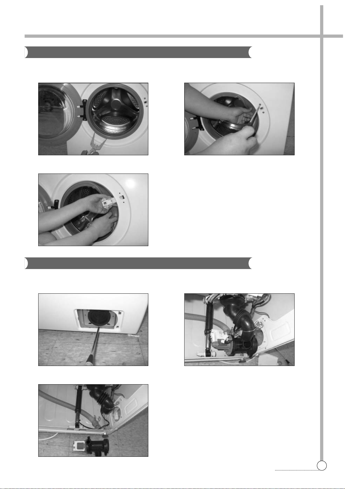
DOOR LOCK SWITCH
1 Open the door and remove the clamp door as. 2 Separate the gasket from the cabinet front and remove
two screws.
DRAIN PUMP
3 Remove the door lock switch from the cabinet front .
1 Separate the cover pump from the cabinet front and
remove screw.
2 Lay the right-side of the washer on the floor. And sepa
rate connectors and hose drain from the pump.
3 Remove the hose drain o from the pump.
10
DIRECTION FOR DISASSEMBLY
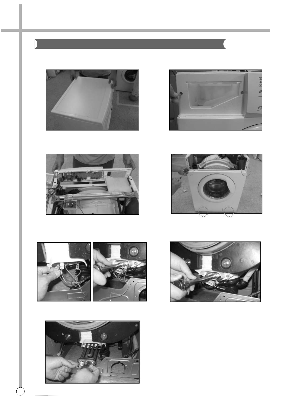
HEATER AND THERMISTOR
1 Separate the plate t as from the washer.
(Remove two screws at rear)
2 Separate the case detergent as and remove two
screws from panel f.
3 Separate the panel f as from the washer. 4 Separate the cabinet front from the washer.
(Remove the clamp door as and 4 screws)
5 Separate connectors from the heater and remove the
nut by using a box wrench.
6 Remove the earth terminal and loosen the nut by using
a box wrench
7 Pull out the heater from the tub.
11
DIRECTION FOR DISASSEMBLY
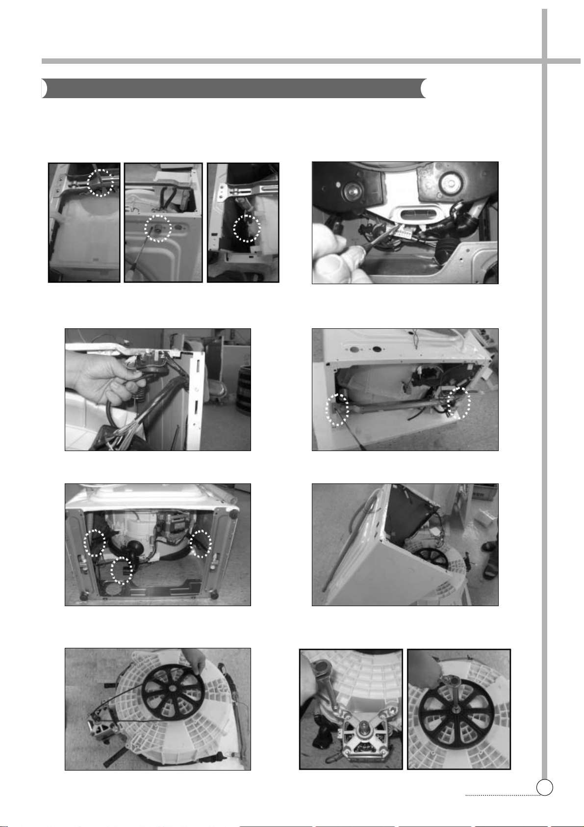
UNIVERSAL MOTOR
1 Separate the box inlet as from the washer.
(remove screws and hose inlet)
2 Remove the screw of the motor connector.
And separate the connector from the tub.
Firstly, you have to do from 1 to 5 of HEATER AND THERMISTOR DISASSEMBLY.
3 Separate the hose air from the sensor pressure. 4 Lay the front-side of washer on the floor.
And remove four screws.
5 Separate two dampers and the hose drain. 6 Lift up the cabinet as.
7 Separate the belt. 8 Remove two screws from the motor and remove the
screw from the drum using a box wrench.
5. EXPLODE VIEW AND PARTS LIST
12
EXPLODE VIEW AND PARTS LIST
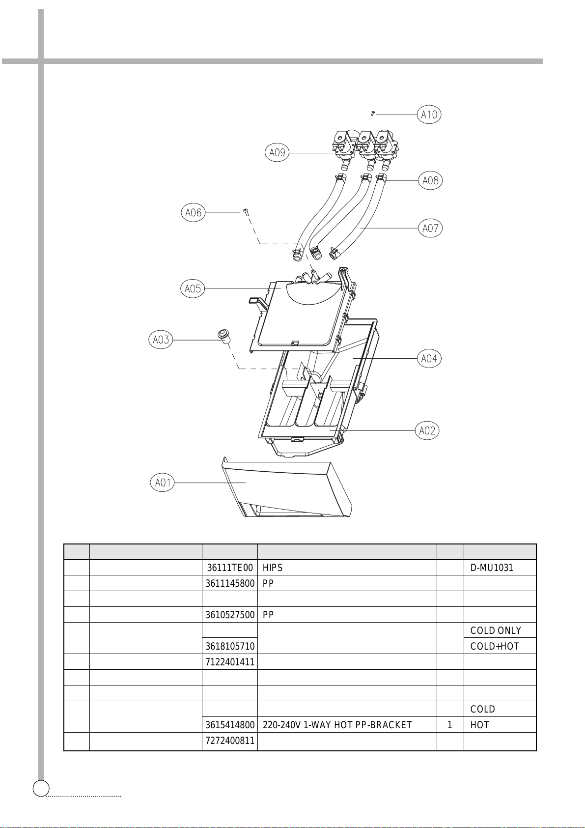
■ BOX INLET AS
No. PART NAME PART CODE SPECIFICATION Q'TY REMARK
A01 HANDLE CASE 36111TE00 HIPS 1 D-MU1031
A02 CASE DETERGENT 3611145800 PP 1
A03 CAP SOFTENER 3610907800 PP 1
A04 BOX INLET 3610527500 PP 1
A05 NOZZLE AS
3618105700
NOZZLE TOP + NOZZLE UNDER 1
COLD ONLY
3618105710 COLD+HOT
A06 SCREW TAPPING 7122401411 T2S TRS 4X14 MFZN 1
A07 HOSE WATER SUPPLY 3613268900 EPDM ID=9.5 OD=14.5 L=215 2(1) COLD(HOT)
A08 CLAMP HOSE 3611205800 ID=13.8 W=10.0 0.9T 4(2) COLD(HOT)
A09 VALVE INLET
3615414910 220-240V 2-WAY NYLON/BRACKET VDE 1 COLD
3615414800 220-240V 1-WAY HOT PP-BRACKET 1 HOT
A10 SCREW TAPTITE 7272400811 TT3 TRS 4X8 MFZN 2
NO DISPONIBLE
NO DISPONIBLE
BOX INLET AS:
3610528010
PEDIR: 3610528010
COMPATIBLE:
3615416820
CASE DETERGENT
AS:
3611147310
PEDIR: 3611147310
PEDIR: 3611147310
 Loading...