

Daewoo DT-K5623P-KS3 User Manual

TIME LAPSE RECORDER WITH DIGITAL SHUTTLE
24 HOUR REAL TIME
User’s Guide
EV-VCR024R
Be sure to read carefully and follow all the SAFETY
INFORMATION on page i.
Keep the manual in a safe place for future reference.
i.
Time Lapse Video Cassette Recorder
AUTO SET
C
H
.
O
P
E
J
E
C
T
Worth Knowing
Please keep the video machine's guarantee card and receipt safe for warranty purposes.
Precautions
◆ Read carefully through this manual to familiarize yourself with this
high–quality Time Lapse video cassette recorder.
◆ Make sure the rating of your household electricity supply matches that
shown on the back of the Time Lapse video cassette recorder.
◆ Refer to this chapter and the "Initial installation" chapter to help you
install and adjust your Time Lapse video cassette recorder.
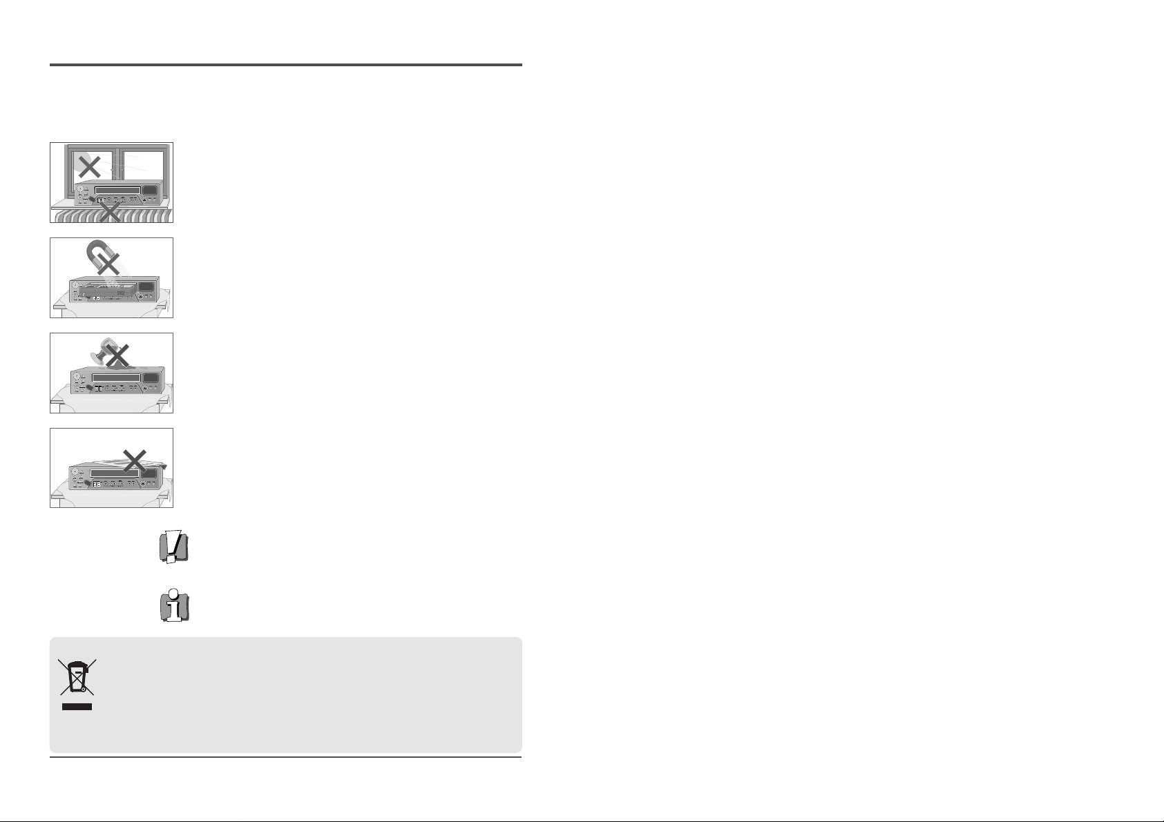
Do not ...
... expose the Time Lapse video cassette recorder to high levels of humidity
and heat, to avoid the risk of fire and electric shock.
... open the Time Lapse video cassette recorder. Have a qualified technician
carry out repairs.
... connect the Time Lapse video cassette recorder to the power supply if
you have just moved it from a cold to warm environment. This can result
in condensation inside the recorder and cause serious damage to the
machine and cassettes. Wait around two hours to allow it to reach room
temperature.
Make sure ...
... the recorder is placed on a steady, flat surface.
... you place the recorder where there is good ventilation all around.
... you clean the recorder only with a soft, lint–free cloth; do not use
aggressive or alcohol–based cleaning agents.
... you disconnect the power supply if the recorder appears to be working
incorrectly, is making an unusual sound, has a strange smell, has smoke
emitting from it or liquids have got inside it. Have a qualified technician
check the recorder.
... you disconnect the power supply and aerial if you will not be using the
recorder for a long period or during a thunderstorm.
For your own safety!
◆ There are no components in this Time Lapse video cassette recorder
you can service or repair yourself.
◆ Do not open the case of the Time Lapse video cassette recorder. Only
allow qualified personnel to repair or service your set.
◆ This Time Lapse video cassette recorder is designed for continuous
operation. Switching it off does not disconnect it from the mains
(stand–by). To disconnect it from the mains, you have to unplug it.
◆ Recording any copyright protected material may infringe a copyright.
Disposal of Used Electrical & Electronic Equipment
The meaning of the symbol on the product, its accessory or packaging indicates that this product shall not
be treated as household waste. Please, dispose of this equipment at your applicable collection point for the
recycling of electrical & electronic equipments waste. In the European Union and Other European countries
which there are separate collection systems for used electrical and electronic product. By ensuring the
correct disposal of this product, you will help prevent potentially hazardous to the environment and to
human health, which could otherwise be caused by unsuitable waste handling of this product. The recycling
of materials will help conserve natural resources. Please do not therefore dispose of your old electrical and electronic
equipment with your household waste. For more detailed information about recycling of this product, please contact
your local city office, your household waste disposal service or the shop where you purchased the product.
1
Time Lapse Video Cassette Recorder
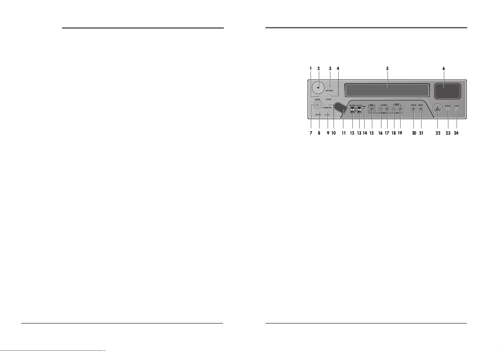
Front Panel
Locations of controls and indicators
1 STOP button
2 REC button
3 REC CHECK button
4 EJECT button
5 CASSETTE LOADING
DOOR
6 DISPLAY PANEL
7 PLAY button
8 REW button
9 FF button
10 PAUSE/STILL button
11 REMOTE SENSOR
12 HIGH-PICTURE switch
13 SET LOCK switch
14 RESET button
15 MENU button
16 SHIFT(†) /
TRACKING (-) button
17 SHIFT(√) /
TRACKING (+) button
18 REC/PLAY SPEED(†)
button (SET - button)
19 REC/PLAY SPEED(…)
button(SET + button)
20 AUDIO ON button
21 DISPLAY button
22 STANDBY/ON button
23 COUNTER button
24 CLEAR button
Time Lapse Video Cassette Recorder
Locations of controls and indicators .............................................................................................. 1
Front Panel .............................................................................................................. 1
Digital Display ......................................................................................................... 2
Back Panel .............................................................................................................. 4
Remote Control ....................................................................................................... 5
Connections ................................................................................................................................. 6
Video Cassettes Tapes .................................................................................................................. 7
Types of On-screen displays and Display Sequence ...................................................................... 8
Setting the Clock ........................................................................................................................ 10
Changing the On-Screen Display ................................................................................................ 12
Normal Recording ...................................................................................................................... 14
Program Timer Recording .......................................................................................................... 16
Alarm Recording ........................................................................................................................ 20
Panic Recording ......................................................................................................................... 23
Series Recording ........................................................................................................................ 23
Autorepeat Recording ................................................................................................................ 25
Normal Playback ....................................................................................................................... 26
Normal Playback ................................................................................................... 26
Tracking Control / Vertical Lock Control ............................................................... 26
Audio Playback ...................................................................................................... 27
Special Playback ........................................................................................................................ 28
Digital Shuttle .........................................................................................................28
Reverse Play / Picture Search .................................................................................29
Still Image ............................................................................................................ 29
Recording Check / Alarm Search ........................................................................... 30
Alarm Scan / Index Search .................................................................................... 31
Other Functions .......................................................................................................................... 32
Tape counter (Zero Search) .................................................................................. 32
Setting the Security Lock (Set Lock) ...................................................................... 33
Setting the HIGH PICTURE ..................................................................................... 33
Setting the SW Out Terminal Output ...................................................................... 34
Setting the Buzzer .................................................................................................. 35
Checking the Alarm Recording Times .................................................................... 36
Checking Power Loss Times .................................................................................. 36
Setting In/Out terminals ......................................................................................... 37
Daily Inspection ......................................................................................................................... 42
Troubleshooting Guide ............................................................................................................... 43
Specifications ............................................................................................................................. 45
Contents
3
Time Lapse Video Cassette Recorder
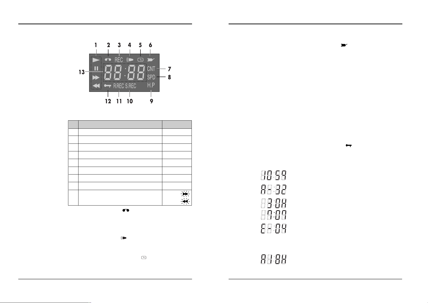
6 Power Loss indicator :
Flashes on after power loss.
7 CNT indicator : CNT
Comes on when the tape or alarm counter is on.
8 SPD indicator : SPD
Comes on when the play or recording speed is on.
9 HIGH PICTURE indicator : H.P
Comes on when the HIGH PICTURE sw is set to the “ON”
position.
10 S.REC indicator : S.REC
Comes on when “YES” is selected in the menu for the
series recording.
11 R.REC indicator : R.REC
Comes on when “YES” is selected in the menu for the
repeat recording.
12 SET LOCK SW indicator :
Comes on when the SET LOCK sw is set to the “ON”
position.
13 Mode display
• TAPE COUNTER display (eg:10:HOUR,59:MINUTE)
- Maximum Hour : 19 - Maximum Minute : 59
• ALARM COUNTER display (eg: A:Alarm , 32:Alarm No.)
• PLAY/REC SPEED display (eg: 30H:Play/Recording
Speed)
• TIME display (eg: 7:HOUR , 07:MINUTE)
• ERROR display (eg: E:Error , 04:Error No.)
- E-01 : The cassette cannot be loaded or unloaded.
- E-02 : The tape stops.
- E-03 : The drum can not rotate properly.
- E-04 : The tape is cut/broken.
• AUDIO ON display (eg: A:Audio , 18H:Play Speed)
2
Time Lapse Video Cassette Recorder
Digital Display
1 Operation Indicators display the actual operation
mode.
2 Cassette indicator :
Comes on when a cassette is loaded.
3 Record check indicator : REC
Flashes on during record check.
4 Alarm indicator :
Flashes on when an alarm is being recorded and stops
flashing after alarm recording.
5 Timer Recording indicator :
Comes on when in timer recording stand-by mode, or
during a timer recording.
Operation Mode Indicator
1 Record (REC) REC
2 Record pause (REC PAUSE) REC + »
3 Playback (PLAY) √
4 Still image (STILL) √+ »
5 Fast forward (FF) √√
6 Rewind (REW) œœ
7 CUE (CUE)+ √+ √√
8 Review (REVIEW)+ √+œœ
9 Slow (Pause Still + FF, √+ »+
Pause Still + REW) √+ »+
5
Time Lapse Video Cassette Recorder
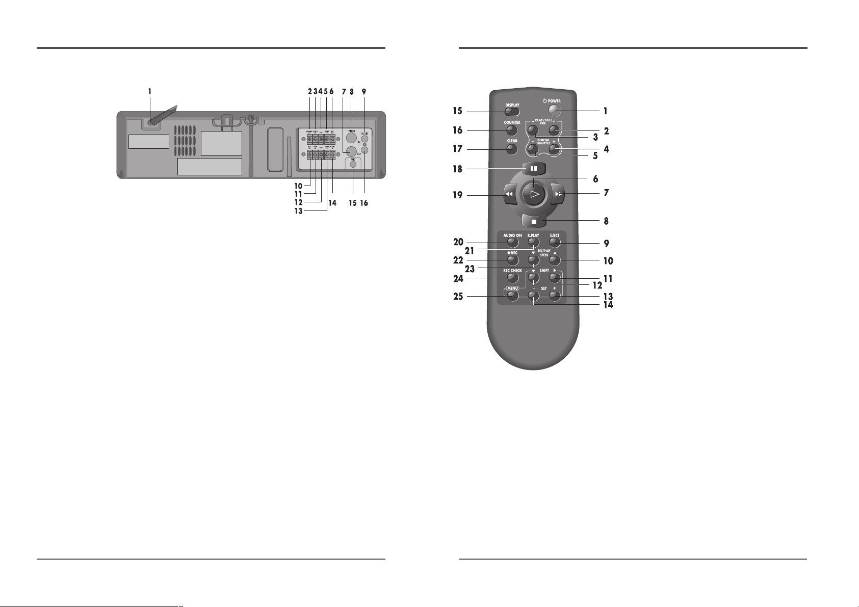
Remote Control
1 POWER button
2 PLAY/STILL TRACKING + button
3 PLAY/STILL TRACKING - button
4 DIGITAL SHUTTLE + button
5 DIGITAL SHUTTLE - button
6 PLAY √ button
7 FF √√ button
8 STOP ■ button
9 EJECT button
10 REC/PLAY SPEED… button
11 SHIFT √ button
12 SHIFT † button
13 SET + button
14 SET - button
15 DISPLAY button
16 COUNTER button
17 CLEAR button
18 PAUSE/STILL button
19 REW œœ button
20 AUDIO ON button
21 REVERSE PLAY button
22 ● REC button
23 REC/PLAY SPEED† button
24 REC CHECK button
25 MENU button
4
Time Lapse Video Cassette Recorder
Back Panel
1 AC POWER CORD
2 WARNING OUT terminal
3 SERIES IN terminal
4 COM terminal
5 SERIES OUT terminal
6 SW OUT terminal
7 VIDEO OUT jack
8 VIDEO IN jack
9 AUDIO IN jack
10 TAPE END terminal
11 PANIC IN terminal
12 COM terminal
13 ALARM OUT terminal
14 ALARM IN terminal
15 MIC(microphone input) jack
16 AUDIO OUT jack
7
Time Lapse Video Cassette Recorder
6
Time Lapse Video Cassette Recorder
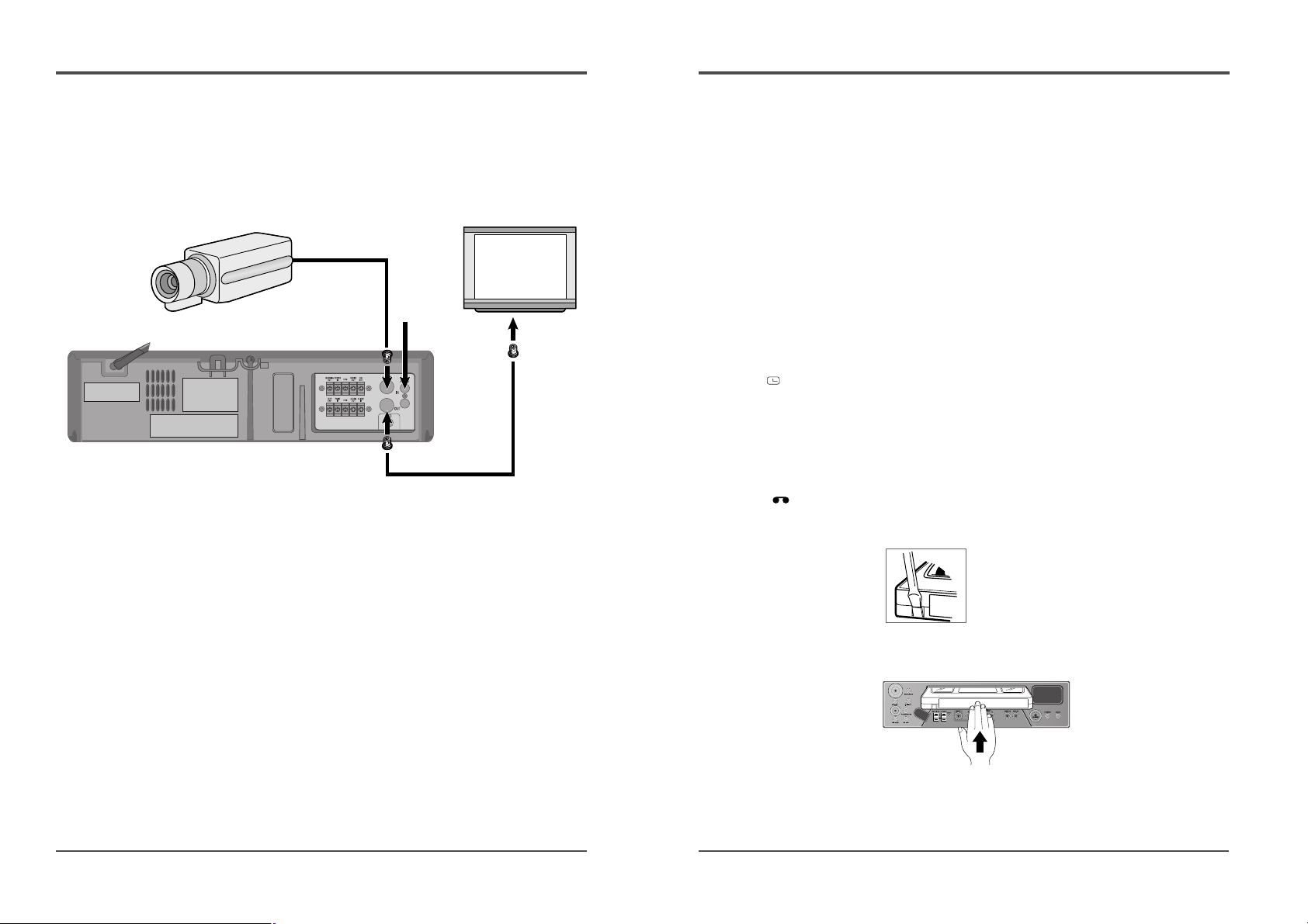
Connections
Connect the video camera and monitor TV as shown in
the figure below.
NOTE : Make sure to turn the power off on all devices
before making the connections.
Power Cord Installation
Insert the plug of the power cord into an outlet.
Video Cassettes Tapes
Use only video cassette tapes bearing the $ logo.
This VCR was primarily designed for use with E-180
cassette tapes. It is recommended to use E-180 VHS or E240 VHS video cassette tapes for optimal performance.
Handling Cassette Tapes
Cassette tapes should always be stored vertically in their
cases, away from high temperatures, magnetic fields,
direct sunlight, dirt, dust and locations subject to mold
formation.
Do not tamper with the cassette mechanism.
Never touch the tape with your fingers.
Protect cassette tapes from shocks or strong vibrations.
To Protect your recordings
After having recorded a tape, if you wish to keep the
recording, use a flathead screwdriver to break off the
erasure-prevention tab on the cassette.
To record again on a tape without erasure-prevention tab,
cover the hole with adhesive tape.
Erasure-prevention tab
To prevent accidental erasure, remove the
tab after recording.
To record again, cover the hole with vinyl
tape.
Loading
Place the cassette, label
side up, in the loading
slot. Gently push the
center of the cassette
until it is loaded
automatically.
Unloading
In STOP mode, press the EJECT button. The cassette is
automatically ejected.
✔
• If you try to record on a
cassette without the erasureprevention tab, the VCR will
eject the cassette.
• If the TIMER button is
pressed when a cassette
without the erasureprevention tab is loaded,
the VCR will eject the
cassette, the timer recording
indicator ( ) will start
flashing and a buzzer will
sound if “YES” is set in the
menu for buzzer.
✔
• When the cassette is
loaded, the cassette
indicator “ “ will light
on the display panel.
• The counter display will
switch to the reset counter
“0H 00M 00S” display on
the monitor screen. (“0H
00M” on the display
panel.)
✔
• Do not insert any object in
the cassette loading slot, as
that may cause injury and
damage to the VCR.
• If your hand gets stuck in
the cassette loading slot,
unplug the power cord and
consult the dealer where the
unit was bought. Do not
forcibly pull the hand out as
that may cause severe
injuries.
Video camera
(sold separately)
To VIDEO OUT terminal
To VIDEO IN
terminal
From an
external audio
source
Monitor TV (sold separately)
9
Time Lapse Video Cassette Recorder
8
Time Lapse Video Cassette Recorder
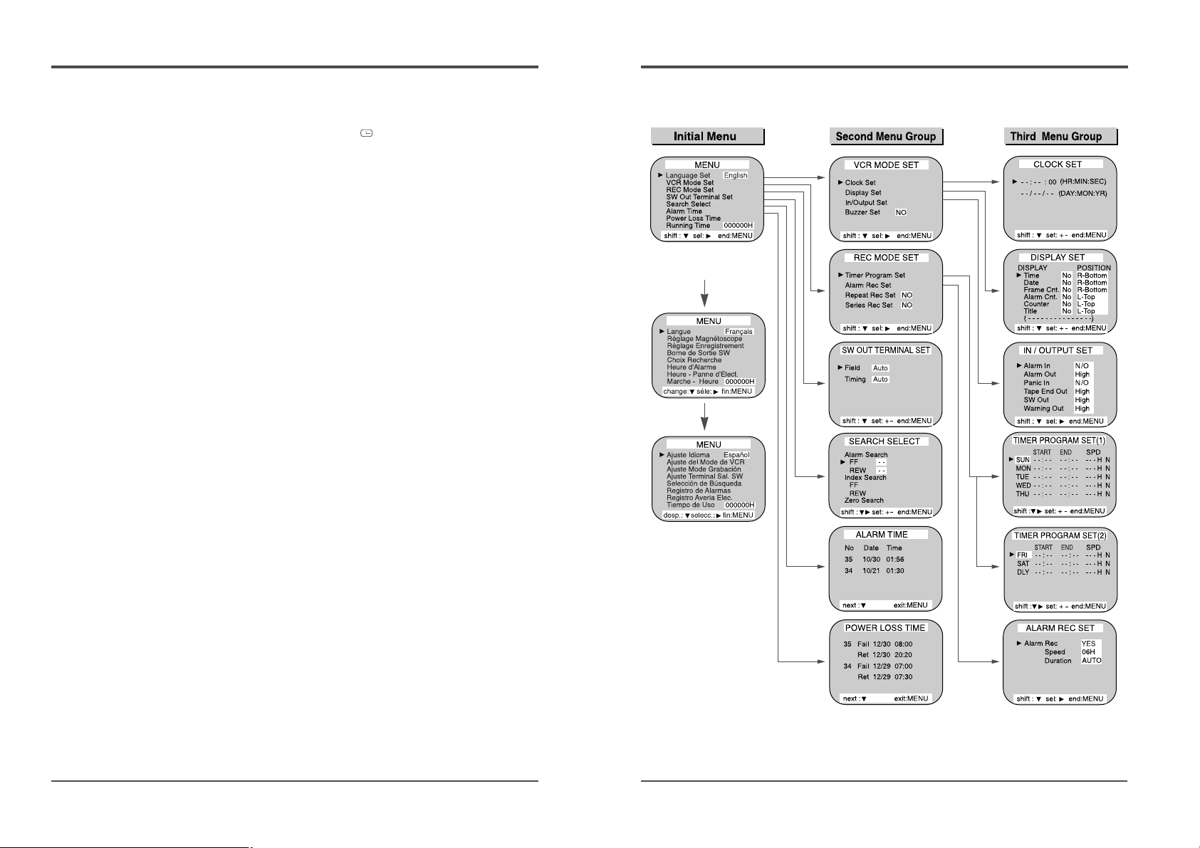
Types of On-screen displays and Display Sequence
• If the VCR is in timer recording stand-by mode (the “ ” indicator is displayed on
the display panel), the on-screen displays will not be available. First press the
STANDBY/ON(POWER) button, to cancel the recording stand-by mode, then proceed
with the VCR programming. When finished, press the STANDBY/ON(POWER) button
again to return the VCR to timer recording stand-by mode.
• When a menu is displayed, recording will not be possible.
• Press the MENU button three times, the setting procedure is now completed and the
normal screen is displayed.
• During recording or playback the menus cannot be displayed.
• Press the MENU button. (First time)
• Press the SHIFT† button to move the arrow mark (√) downward for the
desired item.
• Press the SHIFT√ button to select the desired item, then the desired menu is
displayed.
• Press the MENU button to return to the normal screen from the initial menu.
• Press the SHIFT√ button to select the desired item.
• Press the SET - (or +) button to set or Press the SHIFT√ button to select
“YES” or “NO”.
• Press the MENU button to return to the initial menu.
• Press the SHIFT√ (or SHIFT†)button to select the desired item.
• Press the SET - (or +) button to set or Press the SHIFT√ button to select.
• Press the MENU button to return to the previous menu.
A
B
C
A
B
C
11
Time Lapse Video Cassette Recorder
6 Press the SET - (or +) button to set the minutes (eg
: 30), then press the SHIFT√ button.
7 The seconds are already set to “00”.
8 Press the SHIFT√ button.
9 Press the SET - (or +) button to set the month (eg :
04), then press the SHIFT√ button.
10 Press the SET - (or +) button to set the day (eg :
12), then press the SHIFT√ button.
11 Press the SET - (or +) button to set the year (eg : 04
for 2004).
• The last 2 digits only are displayed.
• The day of the week is set automatically.
12 Press the MENU button three times, the normal
screen is displayed.
• The setting procedure is now complete.
10
Time Lapse Video Cassette Recorder
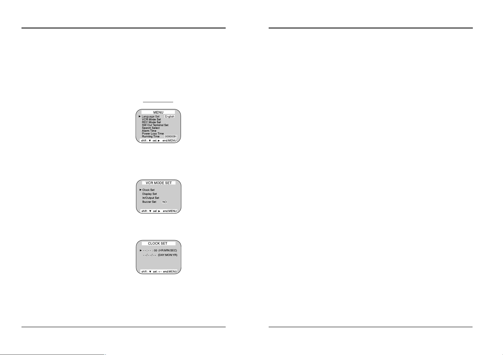
Setting the Clock
Example: To set the clock to April 12, 2004 at 9:30
Clock Setting
1 Turn the power on to all devices used.
2 Press the MENU button, the initial MENU is displayed.
The arrow mark (√) is located in “VCR Mode Set”.
Initial MENU
3 Press the SHIFT√ button, the VCR MODE SET menu
is displayed. The arrow mark (√) is located in
“Clock Set”.
4 Press the SHIFT√ button, the CLOCK SET menu is
displayed.
5 Press the SET - (or +) button to set the hours (eg :
09), then press the SHIFT√ button.
 Loading...