

Page 1

S/M No. : SN500P-010
Service Manual
Internet Settop Box
CHASSIS : SN-500
Model :
DSN-9070
DSN-9071
DAEWOO ELECTRONICS CO., LTD
http : //svc.dwe.co.kr
OCT. 1999
Page 2

TABLE OF CONTENTS
1. Instruction Manual ....................................................................................................................... 1
2. Specification................................................................................................................................. 13
3. Block Diagram.............................................................................................................................. 14
4. Description of the Circuit Operation .......................................................................................... 15
5. Trouble Shooting.......................................................................................................................... 17
6. Circuit Diagram............................................................................................................................. 26
7. Exploded View.............................................................................................................................. 32
8. Packing View ................................................................................................................................ 33
Page 3
1
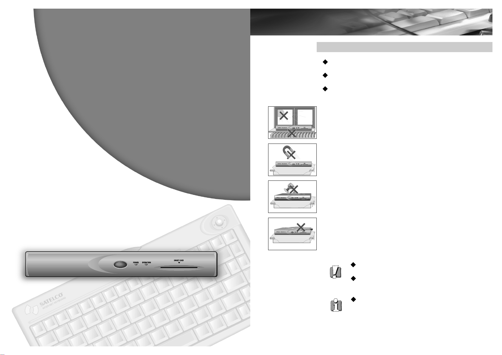
PRECAUTIONS
Read carefully through this manual to familiarize yourself with this highquality “set-top box”.
Make sure the rating of your household electricity supply matches that
shown on the power adapter.
Refer to this chapter and the "Initial installation" chapter to help you
install and adjust your “set-top box”.
Do not ...
... expose the “set-top box” to high levels of humidity and heat, to avoid
the risk of fire and electric shock.
...
open the “ set-top box”. Have a qualified technician carry out repairs.
... connect the “set-top box” to the power supply if you have just moved
it from a cold to warm environment. This can result in condensation
inside the “set-top box” and cause serious damage to the machine.
Wait around two hours to allow it to reach room temperature.
Make sure ...
... the “set-top box” is placed on a steady, flat surface.
... you place the “set-top box” where there is good ventilation all around.
... you clean the “set-top box” only with a soft, lint-free cloth; do not use
aggressive or alcohol-based cleaning agents.
... you disconnect the power supply if the “set-top box” appears to be
working incorrectly, is making an unusual sound, has a strange smell,
has smoke emitting from it or liquids have got inside it. Have a qualified
technician check the box.
... you disconnect the power supply and aerial if you will not be using the
“set-top box” for a long period or during a thunderstorm.
For your own safety!
There are no components in this “set-top box” you can
service or repair yourself.
Do not open the case of the “set-top box”. Only allow
qualified personnel to repair or service your set.
This “set-top box” is designed for continuous operation.
Switching it off does not disconnect it from the mains
(stand-by). To disconnect it from the mains, you have to
Instruction
Manual
1
unplug it.
Page 4

32
CONTENTS
INTRODUCTION
Features
_______________________
3
Package contents
________________
4
Name of parts
___________________
5
CONNECTING Y OUR SYSTEM ___________ 8
INITIAL SETUP
Setting the network ______________
9
WEB BROWSING
Surfing the internet
______________
11
Setting the browser _____________
16
Setting the printer
_______________
17
E-MAIL
Setting E-mail
__________________
18
E-mail _______________________ 19
OTHER FUNCTIONS
Upgrade the software
____________
22
Error diagnose
_________________
22
Specifications
__________________
23
Thank you very much for purchasing the Internet Set-top Box. To enjoy
the Internet with this Set-top Box, you are recommended to subscribe
to a local network. And for better and easier use of this product,
please read through the following chapters of this manual carefully.
This chapter shows you the key features of the Set-top Box and
reviews package contents and name of parts.
As a home multimedia terminal, this Set-top Box has many useful
features described below. The Set-top Box makes you explore the
Internet easy and fun with features such as :
Browser
- HTML 4.0
- CSS 1.0
- SSL 3.0, TLS 1.0
- JavaScript 1.3
- Cookie & Bookmark
- Off-Line Browsing
E-mail
- POP3 or IMAP4 supported
- Address Book
- Off-Line E-mail
Upgradability through the Internet
Wireless Keyboard with Track-ball
FEATURES
INTRODUCTION
2
Page 5

1. POWER ON/OFF indicator
Indicates whether the set-top box is on or off.
2. OPERATING indicator
Flashes when the set-top box is connecting to your
ISP and when receiving new information. Remains
lit while in use.
3. SMART CARD slot
Allows you to use a Smart Card when the
technology becomes available. Smart Cards, which
are being developed by the finance industry, are
credit cards with an added computer chip that
stores personal information. Smart Cards will make
transactions conducted on the Internet, such as
buying products, paying bills, and banking, safer
and more convenient. Additional accessories may
be required.
4. Wireless keyboard receiving window
5
NAME OF PARTS
4
INTRODUCTION
-CONTINUED
31
24
PACKAGE CONTENTS
Make sure you have received all of the following items in your Internet
Terminal package:
Set-top Box
FRONT PANEL
Telephone linecord ManualVideo/Audio cable
Power Adapter2 BatteriesWireless Keyboard
3
Page 6

7
6
INTRODUCTION
-CONTINUED
1. TRACK-BALL
To move the pointer on the screen.
2. CLICK
To put in practice something that you selected with
the pointer.
3. POWER button (Green)
To turn on the set-top box or turn off.
*
Many buttons in the first row may not works, and
the function of them may be changed for more
convenient use later.
1
2
3
1 2 3
4 5 6 7
1. VIDEO OUTPUT
Connects your set-top box to the video input of your
TV.
2. AUDIO R, L OUTPUT
Connects your set-top box to the right and left audio
inputs of your TV.
3. Phone Wire Port
Connects your set-top box to a telephone jack.
4.
DC INPUT
Connect the power adapter to your set-top box.
5. DC OUTPUT
6. S-VIDEO OUTPUT
Allows you to connect your set-top box to your TV
for better picture quality (if your TV has an S-Video
Input)
7. PRINTER OUTPUT
Allows you to connect your set-top box to a printer.
REAR PANEL
WIRELESS KEYBOARD
4
Page 7

9
INITIAL SET-UP
SETTING THE NETWORK
8
CONNECTING YOUR TV, TEL-LINE, PRINTER
When you turn on the set-top box, the page
will appear.
While initializing the set-top box, the progress
bar will be shown at the bottom of screen
until the initialization is finished.
The left-side page in which you are asked to
select ISP will appear.
Click “Cancel” and “CONNECTION” icon
which is located on the right-bottom of
screen.
CONNECTING YOUR SYSTEM
1. Connecting your TV
Connect audio and video cable to the set-top
box and to audio and video input on your TV .
2. TV with an S-VIDEO jack
If your TV has S-VHS input, connect the S-VHS
cable to the set-top box and your TV.
* S-VHS cable is not supplied.
3. Connecting your Tel-Line
Connect the telephone line from the wall to
the phone jack marked port( )
4. Connecting your power adapter
Connect the power adapter to turn on and off
your set-top.box.
5. Connecting your Printer
1
4
3
2
Power Adapter
5 Printer
5
Page 8

11
SURFING THE INTERNET
10
INITIAL SET-UP
-CONTINUED
In the case of modem type, “Network setup”
screen will appear like left-side. Input the
required information. Please refer to the
below explanation.
ISPTo select the name of ISP.
Tel To type the telephone number of ISP.
ID To input the user ID.
PasswordTo input the user password.
Tone/Pulse To select tone or pulse type in
accordance with your phone dial mode.
Below 6 items are optional.
DNSTo set the “DNS server”.
HTTP Gateway To set the “HTTP Gateway”.
Proxy To set the “Proxy”.
Time To set the “Time”.
CHAP Server To set the “CHAP server”.
VJ Compression To set the “VJ compression
option”.
When the input is finished, click OK. Then the
initial page will appear.
In the case of LAN type, “Network setup”
screen will appear like left-side page. Input
the required information. Please refer to the
below explanation.
IP Address To type in the IP address.
Gateway To type in the Gateway.
Subnet Mask To type inthe Subnet Mask.
DNSTo type in the DNS.
HTTP Gateway To set the HTTP Gateway.
ProxyTo set the “Proxy”.
TimeTo set the “Time”.
Please check the above information from the
network manager.
“BROWSER”, “E-MAIL”, “SETUP” and
“CONNECTION” icons will be shown at the
right-bottom of screen.
“BROWSER” icon.
“E-MAIL” icon.
“SETUP” icon.
“CONNECTION” icon.
Click the “BROWSER” icon.
Then the input box and menu icons will be
shown at the bottom of screen.
Type in the address of site which you want to
visit, and click the “go”.
The desired web-site will appear.
WEB BROWSING
6
Page 9

1312
WEB BROWSING
-CONTINUED
FIND
u This “find” icon is used to look for a word in
the current web-site.
1. Click on ‘find’ icon and then the following text
box will appear at the bottom of the screen.
2. Type in the word that you want to look for in
the current web-site and choose the options
(please refer to the following explanation on
each option).
Input Box To type in the word which you
want to look for
Case To decide to look for the word
distinguishing a capital from a small letter
.
Upper To decide to look for the word in the
upper part of the current page on screen
Lower To decide to look for the word in the
lower part of the current page on screen
3. Click ‘find’ icon to start looking for the word
and ‘cancel’ to stop finding.
INPUT BOX
Type in the address of the site which you want
to visit, and click the “go” icon. In case that
the address of the site is in the form of
‘www.???.com’, you may type in the middle
part of the full address. For example, you can
just type in ‘yahoo’ for ‘www.yahoo.com’.
Otherwise, you have to type in the full address
like 'www.w3.org'.
If you click this icon, the latest ten (10) sites
which you have visited will be shown.
GO
This button makes the browser start when you
typed in the URL in the Input Box.
BACKWARD & FORWARD
These “back” and “forward" icons are used to
move on to the previous and the next websites. Just click on these icons to move on.
And if you click on “arrow” icons right-sided,
the sites which you have visited will be
shown.
RELOAD
Click on this icon to reload the entire web
site.
STOP
u While downloading a certain site, just click on
this icon to stop downloading.
7
Page 10

1514
BOOKMARK
You can memorize more than 1,000 of your
favorite web-sites, and also categorize those
sites into 12 different categories (folders). So,
you can visit the desired web-site by just
clicking the name of the site memorized on
each folder, without typing in the address of
the site in the “Input box”.
Click the “bookmark’ icon, and then the
bookmark page will appear.
ADD
1. When your desired web-site is completely
downloaded, click “bookmark’ icon. And then
the text box and icons will appear.
WEB BROWSING
-CONTINUED
2. To add the site in the “bookmark”, click the
‘add’ icon and choose the folder that you want
to put the site into.
3. Click the ‘close’ icon to go back to the Internet
surfing mode.
To use the bookmark later, click the
‘bookmark’ icon, find the site name that your
want to visit and just click on it. Then, the
web-site will be opened.
Add folder To make a new folder
Edit To rename a folder
Del To delete a memorized site
Move To move a memorized site from a
folder to another
8
Page 11

17
SETTING THE PRINTER
SCREEN & SOUND SETUP
Click the “Screen & Sound Setup”, then the
left-side page will appear.
Adjust Screen To set the screen position.
Select SoundTo select the sound effect.
PRINTER SETUP
Click the “Printer Setup” then the left-side
page will appear. You can choose the printer
which you want to use.
You can print out the current web-page to
click the “Print” in the menu icons.
16
SETTING THE BROWSER
u You can set the environment into your desired
one. Just click on the “SETUP” icon, then five
kinds of menu for the environmental set-up
will be seen.
GENERAL SETUP
u Click the “General Setup”, then the left-side
page will appear.
Initial Page Setup To set the firstly shown
site when you turn on set-top box and select if
you set the first page into the Initial
Homepage, the empty screen or the latest
page that you visited recently.
Auto Disconnection To set the time for
automatic disconnection.
Upgrade SetupTo update the software.
APPEARANCE SETUP
u Click the “Appearance Setup”, then the left-
side page will appear.
Default Font SizeTo select the font size of the
letter.
Default Font Face To select the font face of
the letter.
Use scroll bar To use the scroll bar of the
web site.
WEB BROWSING
-CONTINUED
9
Page 12

19
E-MAIL
18
SETTING E-MAIL
Click the ‘E-mail’ icon at the right-bottom of
screen, you will see this page which begins to
check the received mail.
After checking the mail, the left-side page will
be shown.
If you click on a mail, then it will be opened as
below
Reply To compose the response.
Forward To use this icon for forwarding the
mail to someone.
Delete To delete the mail.
Copy To copy the mail (supported only in
IMAP server).
Print To print the mail out.
Previous To show the previous mail.
Next To show the next mail.
Return To go back to the previous page.
E-MAIL-CONTINUED
To make use of this mail function, you have to
set a few things firstly. Click the ‘E-MAIL’ icon
on the page.
Then the left-side page will appear. And after
inputting the required information, press “OK”
icon to start e-mail.
Incoming mailserver
Name To input the address of sever
which you want to use.
Type To select the type of server (IMAP4
or POP3).
Username To input your mail ID.
Password To input your password.
Outgoing mailser ver
Name To input the address of outgoing
server.
E-mail To input your mail address.
10
Page 13

20
ADDRESS
Click this icon and memorize the mail
addresses which you use frequently.
Add To make a new mail address.
Delete To delete a mail address.(First, you
should choose the mail address which you
want to delete.)
Edit To modify the name of mail address.
(First, you should choose the mail address.)
Write To To write a mail.
Save To save this mail address book.
Return To go back to the previous page.
FOLDER
You can make the mail folder if you use
IMAP4 protocol.
Open To open the selected folder.
Add To make a new folder
.
Del To delete a folder.
Rename To change the name of folder.
Return To go back to the previous page.
E-MAIL-CONTINUED
WRITE
Click this icon to compose a new mail, then
the following will be shown.
To To type in the mail address of the
receiver.
Cc To type in the mail address of other person
who receive at the same time.
Subj To write down the subject of message.
Send To send the mail.
Print To print the composed mail out.
Cancel To cancel the composition of mail.
CHECK
Click this icon to check if a new mail has been
delivered.
21122322
Page 14

Terminal DC In/Out (1)
Video Out(1)
Audio (R/L) Out (1)
S-Video Out (1)
A/S Switch (1)
Printer Port (1)
External Phone Wire (1)
Smart Card Slot (1)
Dimensions 290mm X 215mm X 43mm (W X D X H)
Weight
1.25kg
Power Requirements AC 230V
Power Consumption 10W max.
Accessories Size AA Batteries (2)
DC Power Adapter (1)
A/V (Audio/Video) Cable (1)
Telephone Cable (1)
Wireless Keyboard (1)
Display System PAL-B/G, D/K, I
Printer HP 694C, some more kinds of HP and
CANON Printer will be available later
SPECIFICATION
OTHER FUNCTIONS
UPGRADE THE SOFTWARE
The software of this set-top box can be upgraded via the Internet. We
will have the new software on the Internet every time any changes are
made. The local distributor will give the address of download site. To
upgrade the software, go to the given site and click most recent file and
this set-top box will automatically upgrade itself. When completed, it
will turn itself off and restart after a while.
Looks like error? Here are the answers.
Set-top box doesn’t turn on.
o Batteries in the wireless keyboard could be weak. Check the
batteries and replace them, if necessary.
No picture, no sound.
o Make sure the power cord is connected.
o Check that the correct TV/Video setting is selected.
ERROR DIAGNOSE
12
Page 15

2. Specifications
Function
Hardware
Software
Model Name
Main Function Internet, E-Mail
Display Type
AC Adaptor Input
DC Input
Power Consumption
Size(W X D X H)
Weight
On TV (NTSC or PAL)
110Vac or 90~260Vac (50
6
Vdc, 1500
15W Under
290 x 208 x 40(mm)
1.25
§¸
Internal side
Processor
DRAM
PROM
Flash ROM
Wireless Keyboard
Printer Port
S-Video Out
C-Video Out
Audio Out(L/R)
Output Type
Connect Type
Smartcard
Browser
Internet Connection
E-Mail
Sound Effect
GIF Animation, JPEG
Anti-Flickering Function
Upgrade Through Network
Help Function
ARM7500FE, 56
16MB(8MB~)
512KB
2MB
Installed
Installed
Installed
Installed
Installed
NTSC-M or PAL-B, D, G, H, I
MODEM or LAN
Installed
HTML 4.0
CSS 1.0
Java Script 1.3
Dynamic HTML
HTTP 1.0
SSL 3.0
TLS 1.0
Bookmark/Cookie/Proxy etc.
Through ISP
PPP, TCP/IP
PAP/CHAP
IMAP or POP3
SMTP
Installed
WAV/PCM Play
Installed
Installed
Possible
Installed
§Ì
§Ö
§Ô/60§Ô)
DSN-9070/9071
¡Ú¡Ú¡Ú
13
Page 16

3. Block Diagram
14
Page 17

4. Description of the Circuit Operation
1. ARM 7500FE PART
The circuit is divided into digital and analogue input/output parts around the ARM 7500FE part.
Two addresses and two data buses are basically served from the ARM 7500FE part.
- RA (DRAM ROW/COLUMN MULTIPLEXED ADDRESSES) uses 12 bits.
- LA (LATCHED ADDRESSES) uses 29 bits.
- D (MAIN DATA BUS) uses 32 bits.
- BD (MAIN EXTERNAL BUS) uses 16 bits.
RA and D are connected to the DRAM (the capacity is 8~16 Mbyte), the main memory, and are used
when the actual program is operated.
2. PROM part
D and LA are connected to the PROM (the capacity is 512 kbyte).
When the power is turned on, the system reads the initial program codes set in the PROM
and loads them onto the memory.
There is a small WEB BROWSER for emergency use in the PROM.
This can be used if there are any problems in the WEB BROWSER.
The small WEB BROWSER can be loaded by operating the power and the A/S SW.
(Turn the power on while pressing the A/S SW, then turn the A/S SW off in 5 sec.)
3. FLASH MEMORY part
BD and LA are connected to FLASH MEMORY (the capacity is 2 Mbyte to 4 Mbyte memories),
which performs the same function as a hard disc in a PC.
The main program, WEB BROWSER, is loaded, and the INTERNET SET TOP BOX operates.
4. RECEIVER CIRCUIT part
These can be used as wireless-type accessories through the receiver circuit composed of receiver devices,
89C2051 and 97L52.
5. PRINTER OUTPUT part
8 bit data is supplied to the printer port from BD through 74HC377 for printing.
The printer control signals are supplied through the 8 bit WIDE IO PORT.
6. VIDEO OUTPUT part
The composite video and S-VHS(Y, C) signals are provided so the the signals can be displayed on the TV using the
CH7001C NTSC ENCODER.
- Horizontal/vertical position change : UP(#26), DOWN(#27), LEFT(#28), RIGHT(#29)
- Flicker filtering : MS0(#11), MS1(#12)
15
Page 18

3. Description of the Circuit Operation
7. CLOCK part
A clock is needed for the main board of the INTERNET SET TOP BOX.
IO CLK(64
and XOUT(14.318§Ö) is supplied to CH7001C.
The clock doubling chip, CH9294, connected to crystal (14.318
The another crystal(64§Ö) supplied IOCLK.
§Ö)
MCLK(56§Ö) and VCLK(25.18§Ö) are supplied to the ARM 7500FE,
§Ö
) taked the role.
8. SOUND OUTPUT part
SOUND OUTPUT is supplied from the ARM 7500FE in digital types.
Analogue signals, R and L, are supplied to the external amplifier through CS4333 (SOUND ENCODER)
using the digital type stereo sound data and the clock.
9. POWER part
DC 6V is applied to the SET from the power Adaptor.
The power LED is turned ON/OFF by receiving signals from regulated Receiver IC.
Stand by 5V is by Metal Oxide type Resister and Zener diode circuit.
Main Vcc is regulated by PQ05RF21 Regulator.
10. MODEM part
Data needs to be added by the vendor.
16
Page 19

5. Trouble Shooting
1. Contents
1) Don’t turn on power LED.
2) No function of wireless keyboard or remocon.
3) Though it turn on the power LED, No raster.
4) No color or Raster with unstable sync.
5) PROM booting
6) Don’t Progress booting
7) Can’t connect ISP
8) Can’t hear sound effect and Playing wave file
9) Can’t print
2. To download a browser for A/S
1) Turn off set
2) Push the A/S button (S002) and turn on set.
3) You should push the A/S button until the green LED goes out
4) Select ‘1. Modem’ or ‘2. Ethernet’
5) Input the required information
6) Then, the set automatically downloads new browser for a few minutes
7) New browser rebooting, automatically
17
Page 20

1) Don’t turn on Power LED
Adapter connection
START
check
N.G
Reconnection
O.K
Adapter output(6Vdc)
check
N.G
Change the adapter
O.K
I005 #40 S/B 5Vdc
check
N.G
SB5V and GND, R088
ZD001,D040
check/Replace
O.K
I005 #40 <-> #1,
I025 #2(VCC) check
O.K
LD001 (LED)
check
O.K
2. No function of
Wireless KBD/Remocon
N.G
N.G
I025 #4 (high) check?
I025 check/Replace
LD001(Red)
Check/Replace
18
Page 21

2) No function of wireless Keyboard(or Remocon)
Keyboard battery
START
check
N.G
Battery change
(AAM *2)
O.K
IP001 #3 SB5V and
IR pulse check
N.G
SB5V Repair and
IP001 Check /Repalce
O.K
X004 Waveform
check
N.G
X004(6Mhz) waveform
check/Replace
O.K
I101 #165,#167,
#168,#169 check
O.K
Change
wireless KBD/Remocon
N.G
19
Between I005 and I101,
Pattern check/Repair
Page 22

3) Though it turn on the Power LED, No Raster.
START
Video cable
check
N.G
Connect correctly,
Change cable
O.K
X001, X003
Waveform check
N.G
X001(64M),
X003(14.318M)
Check/Replace
O.K
I019 #12, #18, #19
Waveform check
N.G
I019 Check/Replace
O.K
I101 RGB, H.V.
Check
N.G
I012, I080~6 Signal
Line Check
O.K
I101 check
O.K
N.G
Move to Item 4
Repair
IC Check/Replace
20
Page 23

4) No color or Raster with unstable sync.
START
I101 R.G.B. H.V.
check
N.G
I101 Check
O.K
I022 #30 NTSC/PAL
check
N.G
Set display system
correctly
O.K
I022 #16(14.318Mhz)
check
N.G
I019 check/Replace
O.K
I022 Check/Replace
21
Page 24

5) PROM booting
Download new browser
6) Don’t progress booting
START
O.K
I008,I009, I015,I016
Connection check
O.K
START
N.G
Repair
Check /Replace
I008,I009, I015,I016
Connection
check
O.K
Modem/Lan
Connection check
O.K
Download new browser
N.G
N.G
Repair
Check /Replace
Connect correctly
Check /Replace
22
Page 25

7) Can’t connect ISP
START
Tel line or Lan line
check
N.G
Connect correctly or
change
Ask ISP or admin
O.K
ISP or Lan Info.
check
N.G
Change setup and try
O.K
Modem or Lan card
check
N.G
Set com2 port and IRQ3.
Replace
O.K
P006 (ISA Slot)
check
O.K
Address, data line
check
O.K
Download new browser
N.G
N.G
Repair or Replace
Repair
23
Page 26

8) Can’t hear sound effect and playing wav file
START
Audio connector
check
N.G
Connect correctly,
Change
O.K
Browser Set up
check
N.G
Set sound effect
correctly
O.K
I020 In/Out
check
N.G
I020 check/Replace
O.K
I101 Check
24
Page 27

9) Can’t print
START
Printer power
N.G
Turn on printer
check
O.K
Printer connector
check
N.G
Connect correctly
Change connector
O.K
Browser Set up
check
N.G
Set printer correctly
O.K
I013 In/Out and
I/O pin check
O.K
I101 check
N.G
25
I013 check/Replace
I/O line Replace
Page 28

5. Circuit Diagram
AE
C035
0.01uF
C037
0.01uF
C041
0.01uF
C043
0.01uF
VCC VCC VCC VCC
LA[2..28]
VCC
223
224
225
LA2
227
LA3
228
LA4
229
LA5
230
LA6
231
LA7
232
LA8
234
LA9
235
LA10
236
LA11
237
LA12
239
LA13
ROM_CS
BD[0..15]
BD0
BD1
BD2
BD3
BD4
BD5
BD6
BD7
BD8
BD9
BD10
BD11
BD12
BD13
BD14
BD15
240
LA14
1
LA15
2
LA16
3
LA17
4
LA18
5
LA19
6
LA20
7
LA21
9
LA22
11
LA23
12
LA24
13
LA25
14
LA26
15
LA27
16
LA28
140
164
163
162
161
160
158
157
156
155
154
150
148
147
146
142
141
87
182
179
178
177
176
175
174
173
172
199
220
221
200
LA0
LA1
LA2
LA3
LA4
LA5
LA6
LA7
LA8
LA9
LA10
LA11
LA12
LA13
LA14
LA15
LA16
LA17
LA18
LA19
LA20
LA21
LA22
LA23
LA24
LA25
LA26
LA27
LA28
NROMCS
BD0
BD1
BD2
BD3
BD4
BD5
BD6
BD7
BD8
BD9
BD10
BD11
BD12
BD13
BD14
BD15
VSS_CORE3
OD0
IOP0
IOP1
IOP2
IOP3
IOP4
IOP5
IOP6
IOP7
NSIOCS1
NPCCS2
NPCCS1
NEASCS
D[0..31]
D31
D30
D29
D28
D27
D26
D25
D24
D23
D21
D20
D19
D18
D17
D16
D15
D14
D13
D9
32
89
153
214
61
91
121
17
18
19
20
22
23
25
26
28
27
29
31
33
34
36
37
38
39
40
42
43
44
45
D31
D30
D29
D28
D27
D26
D25
D24
D22
D23
D21
D20
D19
D18
D17
D16
D15
D14
D13
D12
D11
VDD14
VDD_ATOD
VDD_CORE0
VDD_CORE1
VDD_CORE2
VDD_CORE3
VDD_ANALOG
NIOR
VDD12
VDD11
VDD10
VDD9
VDD8
VDD6
VDD7
VDD5
VDD4
VDD3
VDD2
VDD1
VDD0
OSCDELAY
NRESET
NPOR
SETCS
SNA
SYNC
8
79
56
41
24
72
211
233
216
198
166
149
117
132
106
59
136
139
171
183
137
D10
I101
CL-PS7500FE -56QC
NIOGT
KBCLK
KBDATA
VCLKI
ATODREF
ATOD3
ATOD2
ATOD1
ATOD0
188
168
169
190
122
123
124
125
126
MA[0..11]
D8
D6D5D4
D3
D0
MA11
MA10
MA9
46
48
49
50
51
52
53
54
55
101
102
D9
D8
D7
NXIPLATCH
NXIPMUX16
NBLI
96
195
189
103
D6
D5
D4
D3
D2
D1
D0
RA11
RA10
NTEST
INT9
INT7
NINT8
NINT6
INT5
NINT4
NINT3
INT2
97
99
98
184
100
186
185
192
191
RAS[0..3]
CAS[0..3 ]
WE
C044
WE
VCC
MA3
MA2
MA1
MA0
RAS1
RAS0
CAS3
CAS2
CAS1
CAS0
RAS3
RAS2
105
107
108
109
110
111
112
113
114
116
118
119
120
128
129
131
133
134
RA9
RA8
RA7
RA6
RA5
RA4
RA3
RA2
RA1
RA0
NINT1
MSCLK
MSDATA
NMSCS
NIORQ
IORNW
NCDACK
TC
LNBW
CLK2
165
86
167
201
209
219
218
196
222
205
NWE
NRAS3
NRAS2
NRAS1
NRAS0
NCAS3
NCAS2
NCAS1
NCAS0
90
VIREF
180
ID
62
VDD13
65
VDD_CORE
63
VSS19
64
VSS18
67
VSS_CORE
69
SCLK
71
WS
70
SDCLK
68
SDO
197
NSIOCS2
181
OD1
145
NEVENT2
194
NEVENT1
75
HCLK
143
I_OCLK
213
CPUCLK
152
MEMCLK
206
REF8M
135
OSCPOWER
202
NBLO
203
NRBE
204
NWBE
60
VCLKO
57
PCOMP
73
ECLK
88
HSYNC
93
BOUT
187
READY
138
RESET
217
NCCS
215
NIOW
208
CLK16
212
VSS_CORE2
151
VSS_CORE1
127
VSS_ATOD
95
VSS_ANALOG
66
VSS17
30
VSS_CORE0
10
VSS0
21
VSS1
35
VSS2
47
VSS3
58
VSS4
74
VSS5
85
VSS6
104
VSS7
115
VSS8
130
VSS9
144
VSS10
159
VSS11
170
VSS12
193
VSS13
210
VSS14
226
VSS15
238
VSS16
94
GOUT
92
ROUT
207
CLK8
VSYNC
ED7
ED6
ED5
ED4
ED3
ED2
ED1
ED0
76
77
78
80
81
82
83
84
0.01uF
7.5K
10K
R050
R073
R061 10K
VCC
EV2
LRCLK
SCLK
SDATA
SIOCS2
OD1
EV1
VIDCLK
I_OCLK
CPUCLK
SDATA
SIOCS2
OD1
EV2
EV1
VIDCLK
I_OCLK
CPUCLK
VCCVCC
RED
GREEN
CLK16
IOW
RESET
READY
BLUE LRCLK
R071 10K
R072 10K
OD0
IOP0
IOP1
IOP2
IOP3
IOP4 ROM_CS
IOP5
IOP6
IOP7
PRINTER_CS
FLASH_CS
OD0
PRINTER_CS
IOP0
IOP1
IOP2
IOP3
IOP4
IOP5
IOP6
IOP7
FLASH_CS
IOR
IOR
POR D22
POR
R057 10K
R052 10K
R051 10K
R054 10K
R058 10K
R060 10K
R053 10K
IOGT D12
KBCLK D11
KBDATA D10
BLI D7
INT6 D 2
INT5 D 1
MSCLK MA8
MSDATA MA7
MSCS MA6
IORQ MA5
IORNW MA4
VSYNC
INT6
IOGT
KBCLK
KBDATA
INT5
BLI
MSCLK
MSCS
IORQ
IORNW
VSYNC
MSDATA
3
D030
R034
4.7K
VCC
3
MMBD1203
1 2
MMBD1203
D031
1 2
AEN
N
HSYNC SCLK
RED
GREEN
CLK16
IOW
RESET
READY
BLUE
HSYNC
26
Page 29

5. Circuit Diagram
SB5V SB5V
SB5V
GND
VCC
IR
IP001
TSOP1238
+
3.3uF
R002
C020
330
1
2
3
GND1PVS2SDA3NC14VCC5RST6CLK7NC28SW19SW2
P005
SB5V
IOGT
BLI
10K
R059
10K
R094
SB5V
10K
R096
SMART_C ARD
10
BD[0..3]
10K
R095
10K
R097
SB5V
12
13
14
15
16
17
18
19
5
4
P1_0
P1_1
P1_2
P1_3
P1_7
P1_4
P1_5
P1_6
XTAL1
XTAL2
RESET
P3_0*RX
P3_1*TX
P3_2*I0
P3_3*I1
P3_4*T0
P3_5* T1
P3_7
VCC
I010
1
2
3
6
7
R036
0
R040
0
MSCS BD3
0
SB5V
10K
R0390R038
R092
30
29
21
22
23
24
25
ALE
PSEN
P2_0
P2_1
P2_2
P2_3
GND
8
9
AT89C2051
11
20
10
12
IORNW IOGT
IORQ BLI
C019
0.1uF
IORQ
MSCS
SB5V
IORNW
C013
0.1uF
SB5V
26
27
28
10
11
12
13
14
15
16
17
40
20
VCC
P2_4
P2_5
P2_6
P2_7
P3_0
P3_1
P3_2
P3_3
P3_4
GND
P3_5
P3_6
P3_7
VCC VCC VCC
EV2
EV1
POR
S002
EV2
EV1
POR
R070
10K
R065
10K
C045
R074
10K
3.3uF
+
12
3
4 3
D039
RESET
EA
P0_0
P0_1
P0_2
P0_3
P0_4
P0_5
P0_6
P0_7
P1_0
P1_1
P1_2
P1_3
P1_4
P1_5
P1_6
P1_7
XTAL1
I005
9
31
39
1
2
3
4
38
37
36
35
5
34
33
32
XTAL2
6
7
GMS97L52
8
19
18
MMBD1203
VCC
123
3
6MHZ
ON_OFF
+
SB5V
R001
100K
C018
33uF
R033
4.7K
R032
4.7K
R031
4.7K
R030
4.7K
SB5V
MSCLK
MSCLK
ON_OFF
C002
100pF
C004
100pF
C006
100pF
C008
100pF
MSDATA BD0
KBCLK BD1
KBDATA BD2
KBCLK
KBDATA
MSDATA
2
X004
1
I006
KIA7042AP
Key Board Receiver IC
Smart Card IC
Dependent Configuration Independent Configuration
Main Receiver IC
Receiver Configuration
Key Board-Remocon-Smart card
Bridge IC
R036, R038, R039 R040
* I006 is Optional RESET function
* S002 is A/S Switch for ROM booting
I005
I010
Jumper
27
Page 30

5. Circuit Diagram
C093
RAS1WECAS3
0.01uF
CAS2
MA[0..11]
C091
0.01uF
CAS2
RAS0
WE
CAS3
MA[0..11]
C095
0.01uF
WE
CAS2
RAS2
CAS3CAS1
MA[0..11]
C097
0.01uF
WE
RAS3
CAS3
MA7
MA6
MA8
MA10
MA9
MA5
MA11
1
6
16
21
28
VCC
VCC
VCC
A11(N.C)15A10(N.C)
DQ833DQ934DQ1035DQ11
DQ1238DQ1339DQ1440DQ15
I081
VCC VCC
I080
41
D30
D31
D[16..31]
1
6
VCC
VCC
41
D15
D14
36
D29
D28
D25
D26
D27
MA[0..11] MA[0..11]
MA11
MA10
MA9
16
21
28
VCC
A11(N.C)15A10(N.C)
DQ1238DQ1339DQ1440DQ15
36
D13
D12
D11
D10D9D8D7D6D5D4D3D2D1D0
10
D24
D22
D21
D23
MA8
MA7
MA6
MA5
DQ833DQ934DQ1035DQ11
10
CAS2
MA3
MA4
20
A423A524A625A726A827A9
DQ47DQ58DQ69DQ7
5
D19
D20
MA4
MA3
20
A423A524A625A726A827A9
DQ47DQ58DQ69DQ7
5
WE
MA2
RAS0
CAS3
14
31
A017A118A219A3
nRAS
nUCAS30nLCAS
DQ02DQ13DQ24DQ3
N.C11N.C
N.C
12
32
D18
D16 MA0
D17 MA1
VCC VCC
RAS0
CAS1
MA2
MA1
MA0
RAS0
CAS0WECAS1
14
31
A017A118A219A3
nRAS
nUCAS30nLCAS
DQ02DQ13DQ24DQ3
N.C11N.C
N.C
12
32
VCC
13
29
nW
nOE
VSS
VSS
VSS
KM416C1204BJ 1MB*16
22
CAS0
VSS
22
I083
37
42
C090
0.01uF
WE
VCC
13
29
nW
nOE
VSS
VSS
I082
KM416C1204BJ 1MB*16
37
42
1
6
VCC
41
D30
D31
D[16..31]
1
6
VCC
41
D15
D14
MA10
MA9
MA11
16
21
28
VCC
VCC
A11(N.C)15A10(N.C)
DQ1238DQ1339DQ1440DQ15
36
D29
D28
D25
D26
D27
MA[0..11]
MA11
MA10
MA9
16
21
28
VCC
VCC
A11(N.C)15A10(N.C)
DQ1238DQ1339DQ1440DQ15
36
D13
D12
D11
D10D9D8D7D6D5D4D3D2D1D0
MA7
MA6
MA8
MA5
DQ833DQ934DQ1035DQ11
10
D24
D22
D21
D23
MA8
MA7
MA6
MA5
DQ833DQ934DQ1035DQ11
10
CAS2
MA3
MA4
20
A423A524A625A726A827A9
DQ47DQ58DQ69DQ7
5
D19
D20
MA4
MA3
20
A423A524A625A726A827A9
DQ47DQ58DQ69DQ7
5
WE
MA2
RAS1
CAS3
14
A017A118A219A3
nRAS
nUCAS30nLCAS
DQ02DQ13DQ24DQ3
N.C11N.C
N.C
12
32
D18
D16 MA0
D17 MA1
VCC VCC
RAS1
CAS1
MA2
MA1
MA0
RAS1
14
A017A118A219A3
nRAS
nUCAS30nLCAS
DQ02DQ13DQ24DQ3
N.C11N.C
N.C
12
32
VCC
13
29
31
nW
nOE
VSS
VSS
VSS
KM416C1204BJ 1MB*16
22
37
42
C092
0.01uF
WE
CAS0
CAS0WECAS1
VCC
13
29
31
nW
nOE
VSS
VSS
VSS
KM416C1204BJ 1MB*16
22
37
42
MA8
MA4
MA11
MA9
MA2
MA10
MA3
MA6
MA7
1
VCC
I085
41
D31
D[16..31]
1
VCC
I084
41
D15
MA5
6
16
21
VCC
VCC
D28
D30
D29
6
21
VCC
VCC
D12
D13
D14
20
28
A423A524A625A726A827A9
A11(N.C)15A10(N.C)
DQ47DQ58DQ69DQ7
DQ833DQ934DQ1035DQ11
DQ1238DQ1339DQ1440DQ15
5
10
36
D27
D20
D24
D18
D21
D19
D23
D22
D26
D25
MA[0..11]
MA9
MA11
MA5
MA3
MA2
MA4
MA8
MA10
MA7
MA6
16
20
28
A423A524A625A726A827A9
A11(N.C)15A10(N.C)
DQ47DQ58DQ69DQ7
DQ833DQ934DQ1035DQ11
DQ1238DQ1339DQ1440DQ15
5
10
36
D3
D4
D6
D2
D8
D9
D11
D7
D5
D10
WE
RAS2
CAS3
CAS2
MA0
MA1D1
13
14
29
31
nW
A017A118A219A3
nOE
nRAS
nUCAS30nLCAS
DQ02DQ13DQ24DQ3
N.C11N.C
VSS
N.C
VSS
VSS
KM416C1204BJ 1MB*16
12
22
32
37
42
D17
D16
C094
0.01uF
VCC VCC
CAS0
RAS2
WE
WE
MA1
RAS2
CAS1
MA0
CAS0
VCC VCC
13
14
29
31
nW
A017A118A219A3
nOE
nRAS
nUCAS30nLCAS
DQ02DQ13DQ24DQ3
N.C11N.C
VSS
N.C
VSS
VSS
KM416C1204BJ 1MB*16
12
22
32
37
42
D0
MA9
MA7
MA8
MA11
MA10
1
6
16
21
28
VCC
VCC
VCC
A11(N.C)15A10(N.C)
DQ833DQ934DQ1035DQ11
DQ1238DQ1339DQ1440DQ15
I087
I086
10
36
41
D24
D31
D27
D25
D29
D26
D30
D23
D28
D[16..31]
MA[0..11]
MA7
MA10
MA9
MA8
MA11
1
6
16
21
28
VCC
VCC
VCC
A11(N.C)15A10(N.C)
DQ833DQ934DQ1035DQ11
DQ1238DQ1339DQ1440DQ15
10
36
41
D14
D8
D10
D12
D13
D7
D15
D9
D11
RAS3
MA3
MA5
MA2
MA4
MA6
20
A423A524A625A726A827A9
DQ47DQ58DQ69DQ7
5
D21
D19
D20
D22
D18
MA4
MA3
MA6
MA2
MA5
20
A423A524A625A726A827A9
DQ47DQ58DQ69DQ7
5
D3
D5
D2
D4
D6
WE
MA0D16
MA1
CAS3
CAS2
13
14
29
31
nW
A017A118A219A3
nOE
nRAS
nUCAS30nLCAS
DQ02DQ13DQ24DQ3
N.C11N.C
VSS
N.C
VSS
VSS
KM416C1204BJ 1MB*16
12
22
32
37
42
D17
C096
0.01uF
VCC VCC
CAS0 CAS2
RAS3
WE
CAS1
RAS3
WE
MA0
CAS0
CAS1
MA1
13
14
29
31
nW
A017A118A219A3
nOE
nRAS
nUCAS30nLCAS
DQ02DQ13DQ24DQ3
N.C11N.C
VSS
N.C
VSS
VSS
KM416C1204BJ 1MB*16
12
22
32
37
42
D0
D1
D[0..15]
D[0..15]
D[0..31]
D19
D18
D17
D16
D15
64
MA012MA113MA214MA315MA416MA517MA618MA728MA831MA932MA1019MA11
I099
29
VCC VCC
MA11 D31
MA10 D30
MA9 D29
MA8 D28
MA7 D27
MA6 D26
MA[0..11]
RAS133RAS034RAS_145RAS_044CAS040CAS143CAS241CAS342WE47PD167PD268PD369PD470NC135NC236NC337NC438VSS11VCC110NC511VSS239VCC2
MA5 D25
MA4 D24
MA3 D23
MA2 D22
MA1 D21
MA0 D20
RAS1
RAS0
RAS1
RAS[0..1]
D[0..15]
D14
D13
D12
D7
D5D4D3D2D1
D0
51
D1053D1155D1257D1361D1463D1565D163D175D187D199D2021D2123D2225D2327D2450D2552D2654D2756D2858D2960D3062D31
CAS3 D11
CAS2 D10
CAS1 D9
CAS0 D8
RAS0
WE D6
CAS[0..3]
WE
46
VCC359VSS3
72
NC671NC766NC848NC9
30
SIMM MODULE DRAM (32BIT DATA, RAS0,1)
D02D14D26D38D420D522D624D726D849D9
D[0..15]
* I099A : 72pin SIMM SOCKET
I080, I081
I080, I081, I082, I083
ON BOARD
SIMM SOCKET
DRAM Configuration
I080, I081, I082, I083, I084, I085
I080, I081, I082, I083, I084, I085, I086, I087
KMM5321204BW
KMM5322204BW
KMM5324104BK
KMM5328104BK
4M byte
8M byte
12M byte
16M byte
32M byte
28
Page 31

5. Circuit Diagram
A
BD15
BD14
BD13
VCC
BD12
12
37
39
41
43
45
47
VCC
DQ13
DQ14
nBYTE
nRESET
DQ15/A-1
C015
0.01uF
IOW
IOR
VCC
BD11
BD10
BD9
BD8
BD2
BD3
BD4
BD5
BD6
BD7
30
32
33
34
35
36
38
40
42
44
DQ8
DQ9
DQ3
DQ4
DQ5
DQ6
DQ7
DQ10
DQ11
DQ12
FLASH_CS2
IOR
IOW
FLASH_CS2
BD0
BD1
11
15
26
28
29
31
nWE
nCE
nOE
DQ0
DQ1
DQ2
RY/nBY
VCC
BD11
BD12
BD13
BD14
BD15
12
36
37
39
41
43
45
47
VCC
DQ12
DQ13
DQ14
nBYTE
nRESET
DQ15/A-1
C017
0.01uF
IOW
IOR
VCC
BD8
BD9
BD10
BD7
BD6
BD5
BD4
BD3
BD2
30
32
33
34
35
38
40
42
44
DQ8
DQ9
DQ3
DQ4
DQ5
DQ6
DQ7
DQ10
DQ11
FLASH_CS4
IOW
IOR
FLASH_CS4
BD1
BD0
11
15
26
28
29
31
nWE
nCE
nOE
DQ0
DQ1
DQ2
RY/nBY
LA21
LA22
LA23
A151A142A133A124A115A106A97A8
A1816A17
A16
I009
LA20
LA[2..20]
VCC
37
VCC
A1816A17
I008
LA20
17
48
LA19
LA18
LA17
BD[0..15] BD[0..15]
12
47
nBYTE
nRESET
A16
17
48
LA19
LA18
LA17
LA16
LA15
LA14
LA13
LA12
BD15
BD14
BD13
BD12
BD11
36
39
41
43
45
DQ12
DQ13
DQ14
DQ15/A-1
A151A142A133A124A115A106A97A8
LA16
LA15
LA14
LA13
LA12
8
LA11
LA10
LA9
BD10
BD9
BD8
30
32
34
DQ9
DQ10
DQ11
8
LA11
LA10
LA9
A718A619A520A421A322A223A124A0
LA8
LA7
LA6
LA5
LA4
VCC
BD3
BD4
BD5
BD6
BD7
35
38
40
42
44
DQ8
DQ3
DQ4
DQ5
DQ6
DQ7
A718A619A520A421A322A223A124A0
LA8
LA7
LA6
LA5
LA4
N.C9N.C
N.C13N.C
VSS
VSS
MBM29F800B-TSOP
10
14
25
27
46
LA3
LA2
VCC
LA21LA21
LA21LA21
C014
0.01uF
IOW
IOR
FLASH_CS1
IOR
IOW
FLASH_CS1
BD0
BD1
BD2
11
15
26
28
29
31
33
nWE
nCE
nOE
DQ0
DQ1
DQ2
RY/nBY
N.C9N.C
N.C13N.C
VSS
VSS
MBM29F800B-TSOP
10
14
25
27
46
LA3
LA2
VCC
A151A142A133A124A115A106A97A8
A1816A17
A16
I016
LA20
LA[2..20]
VCC
37
VCC
A1816A17
I015
LA20
17
48
LA17
LA18
LA19
BD[0..15] BD[0..15]
12
47
nBYTE
nRESET
A151A142A133A124A115A106A97A8
A16
17
48
LA19
LA18
LA17
8
LA9
LA10
LA11
LA12
LA13
LA14
LA15
LA16
BD15
BD14
BD13
BD12
BD11
BD10
BD9
BD8
30
32
34
36
39
41
43
45
DQ9
DQ10
DQ11
DQ12
DQ13
DQ14
DQ15/A-1
8
LA16
LA15
LA14
LA13
LA12
LA11
LA10
LA9
A718A619A520A421A322A223A124A0
LA4
LA5
LA6
LA7
LA8
VCC
BD3
BD4
BD5
BD6
BD7
35
38
40
42
44
DQ8
DQ3
DQ4
DQ5
DQ6
DQ7
A718A619A520A421A322A223A124A0
LA8
LA7
LA6
LA5
LA4
N.C9N.C
N.C13N.C
VSS
VSS
MBM29F800B-TSOP
10
14
25
27
46
LA2
LA3
LA21
LA21
C016
0.01uF
IOW
IOR
FLASH_CS3
IOR
IOW
FLASH_CS3
BD0
BD1
BD2
11
15
26
28
29
31
33
nWE
nCE
nOE
DQ0
DQ1
DQ2
RY/nBY
N.C9N.C
N.C13N.C
VSS
VSS
MBM29F800B-TSOP
10
14
25
27
46
LA3
LA2
VCC VCC
LA21
LA21
R045
0
LA22
R046
0
R047
2A
FLASH_CS
FLASH_CS1
FLASH_CS2
FLASH_CS
FLASH_CS1
FLASH_CS2
VCC
122B132A14
16
_2E15VCC
_1E11A21B31Y041Y151Y261Y37GND
I014
C030
VCC
LA23
0
R048
0
2B
FLASH_CS3
FLASH_CS4
FLASH_CS3
FLASH_CS4
2Y392Y2102Y1112Y0
74HC139D
8
0.01uF
LA[2..20]
D[0..15]
D0D1D2D3D4D5D6D7D8D9D10
21
20
19
18
17
16
15
14
11
D0
D1
D2
D3
D4
D5
D6
D7
A0
A1
A2
A3
A4
A5
A6
I012
LA[2..19]
A7
24
25
26
27
28
29
30
31
32
LA2
LA3
LA4
LA5
LA6
LA7
LA8
LA9
LA10
LA[2..20]
ROM_CS
VCC
D11
D12
D13
D14
D15
10
9
8
7
6
5
4
2
3
1
12
13
D8
D9
D10
D11
A8
A9
A10
A11
35
36
37
38
LA11
LA12
LA13
LA14
44
CE
D12
D13
D14
D15
VPP
NC0
NC1
VCC
GND0
A12
A13
A14
A15
A16
A17
OE
NC2
NC3
GND1
39
40
41
LA15
LA16
LA17
27C4096-44PIN PLCC
42
43
22
23
33
34
LA18
LA19 ROM_CS
IOR
IOR
LA21
0x000000 ~ 0x0FFFFF
C026
0.01uF
VCC
0x100000 ~ 0x1FFFFF
R046, R048
0x200000 ~ 0x2FFFFF
0x300000 ~ 0x3FFFFF
29F800B 29F160D
Flash ROM Configuration
0x000000 ~ 0x07FFFF
0x080000 ~ 0x0FFFFF
I008
I009
R045, R047
0x180000 ~ 0x1FFFFF
0x100000 ~ 0x17FFFF
I015
I016
Jumper
29F160D:Pin9-A19,Pin14-nWP
E28F800B5B(intel):Pin12-nRP,Pin13-VPP,Pin14-nWP,Pin15-NC
* I012A : 44pin PLCC SOCKET
* Notice
29
Page 32

5. Circuit Diagram
CPUCLK
CPUCLK
RED
GREEN
BLUE
HSYNC
VSYNC
RED
GREEN
BLUE
VSYNC
HSYNC
VCC
2
3
4
6
8
VCC1RED
BLUE
GND17GND2
GREEN
HSYNC5VSYNC
P004
VIDCLK
C072
0.01uF
VIDCLK
C071
0.01uF
R086
180
R084
180
VCC
19
12
9
11
3
4
5
7
MS0
MS1
MS2
FS0
FS1
VCLK
MCLK
I019
STROBE
XO_FIN1VDD0
GND1
AVDD
AGND
GND0
6
13
14
15
16
10
2
VCC
R111
1M
X003
11pF
11pF
C039
14.318MHz
C038
R080
10K
VCC
4
2
44
34
R
G
B
H35V
VGA_OUT
Y
C
I022
21
23
19
BL020
BL019
VCC VCC
C042
0.01uF
VCC
8
20
FS2
FS3
VDD1
CH9294G
XI
GND2
XOUT
17
18
C067
0.01uF
C066
10uF
+
VCC
R085
180
BL021
C053
AVDD
C052
C057
C059
0.001uF
VR003
VR 10K
VR002
VR 10K
VR001
VR 10K
R063
75
R055
75
R049
75
C202
120pF
C201
120pF
C200
120pF
8
33
15
16
37
38
43
XI
PD0
AVDD13 AVDD0
STROBE6 CLKOUT
*CLKEN7UNDRS C
RSET
360
R081
75
R082
R083
75
VCC
D034
MMBD1203
1 2
AVDD2
XO_FIN
CVBS
VREF1
22
41
75
R079
BL015
3
BL022
BL023
0.1uF
0.1uF
0.1uF
VDD
C054
C061
C058
C065
0.1uF
C063
C064
0.1uF
DVDD
I021
VCC
R044
25
13
32UP26
VDD018VDD1
DVDD09DVDD1
DVDD2
VREF2
*TEST
AGND1
39
36
1
C060
2.2uF
+
C055
0.1uF
0.1uF
C102
0.1uF
0.1uF
0.1uF
VCC
SIOCS2
IOW
BD[0..7]
SIOCS2
IOW
BD0
BD1
3
4
1D513
11
G
D1
D2
CLK
Q1
Q2
GND10VCC
5
2
20
10K
DOWN27LEFT
AGND2
DGND1
DGND2
GND1
GND2
5
10
14
20
24
220pF
I_OCLK
VCC
4
OUT3VCC
NC1GND
X001
64MHz
2
C049
0.01uF
VCC DC6V SB5V GND1 GND2 GND3
VCC DC6V SB5V
BD2
BD3
BD4
BD5
BD6
BD7 I_OCLK
7
8
14
17
18
D3
D4
D6
D7
D8
Q3
Q4
Q5
Q6
Q7
Q8
74HC377D
6
9
12
15
16
19
0
R043
0
R041
28
29
30
12
11
PD117MS1
MS0
RIGHT
NTSC*PAL
DGND3
AGND3
AGND4
31
40
42
R041
R043
R044
CH7001C_V
Display Configuration
Software select
NTSC Fixed
PAL Fixed
VCC
BL016
C056
0.1uF
SDATA
SCLK
LRCLK
CLK16
SDATA
SCLK
LRCLK
CLK16
1
2
3
4
LRCK
MCLK
SDATA
DEMSCLK
AOUTR
GND
VCC
AOUTL
I020
5
6
7
8
VCC
C050
10uF+C047
R077
56K
2.4K
C051
R078
L
BL017
C048
0.01uF
CS4333
VCC
10uF
+
R076
56K
2.4K
0.001uF
C046
0.001uF
R075
R
BL018
C101
220pF
HB-1H3216-700JT
BL015, BL016, BL017, BL018
BL019, BL020, BL021, BL022
BL023
* VR001, VR002, VR003 use white balance control
* C060 is Not stuff to the test pin
* P004 is Optional header for VGA_out
12
3
VCC
12
3
D038
MMBD1203
1R2C3
6Y7
GND1
D037
MMBD1203
GND24GND35GND4
P011
SVHS_AUDIOR
1CV2
3
4
5L6
VCC
GND1
GND2
GND3
P010
VIDEO_AUDIOL
12
3
VCC
12
3
D035
MMBD1203
D036
MMBD1203
30
Page 33

5. Circuit Diagram
43
60
VCC1
SMEMR
IOR45IOW
44
IOW
IOR
PE
BUSY
12
11
36
38
40
34
N5V
VCC2
N12V
AEN11RESET3314.3MHT61IRQ356IRQ455IRQ554IRQ6
IOW
AEN
RESET
CLK16
AUTOFD14ERROR
SLCT
13
15
16
41
P12V
INT6
INT5
INIT
GND0
INT6
SLCTIN17GND018GND119GND220GND3
62
1
32
GND1
GND2
IOCHCK
IRQ7
53
52
3
3
3
3
VCC
BD[8..15]
BD8
74
75
SD873SD9
IRQ935IOCHRDY
SA2364SA2265SA2166SA2067SA1968SA1869SA1770IRQ1083IRQ1184IRQ1285IRQ13
10
LA28
LA27 BD9
LA26 BD10
READY
READY
LA[22..28]
GND422GND523GND624GND7
21
25
1
D009
MMBD1203
2
1
D003
2
MMBD1203
1
D022
2
MMBD1203
12
D017
MMBD1203
BD12
BD15
78
80
96
71
72
89
93
95
94
82
81
63
97
98
VCC
SD1479SD15
SD1176SD1277SD13
SD10
MEMR
MEMW
DREQ0
DREQ591DREQ6
IRQ14
87
86
330
R091
R093
330
LA25 BD11
LA24
LA23 BD13
LA22 BD14
PRINTER
12
3
D021
MMBD1203
1
3
D002
MMBD1203
2
1
3
D001
MMBD1203
2
1
3
D019
2
MMBD1203
12
3
D015
MMBD1203
GND
SBHE
DACK088DACK590DACK692DACK7
DREQ7
IOCS16
MASTER
MEMCS16
CONAT98B
C089
470pF
C088
470pF
C087
470pF
C086
470pF
C085
470pF
C084
470pF
C083
470pF
C082
470pF
C081
470pF
VCC
SB5V
ZD001
LD002
GREEN
MTZJ5.1A
LD001
D040
33_1W
R088
RED
1N4148
C070
47uF/16V
+
2
VO
4
ON*OFF
3
GND
VI
I025
PQ05RF21
1
C069
0.33uF
ON_OFF
OD1
VCC
OD1
ON_OFF
R090
180
R089
180
R103
10K
Q002
SB5V
SB5V
2SC1623
R102
10K
Q001
2SC1623
R101
100K
BD[0..7]
BD7
BD6
BD5
BD4
BD3
BD2
BD1
VCC
BD0
57
51
46
47
58
50
59
2
3
4
5
6
7
8
9
D6
D5
D4
D3
D2
D1
D0
D7
ALE
A19
A18
A17
A16
A15
A14
A13
A12
P006
LA[2..21]
A11
13
14
15
12
16
17
18
19
20
LA21
LA15
LA14
LA13
D02D13D24D35D46D57D68D7
P002
42
37
39
TC
OWS
DREQ149DACK3
DACK2
DACK148DREQ3
DREQ2
REFSH
SMEMW
SYSCLK
A10
A9
A8
A625A5
A7
A4
23
21
22
24
26
27A328A229A130A031
LA9
LA8
LA7
LA6
LA5
LA4
LA3
LA12
LA11
LA10
IOR
STROBE
ACK
9
1
10
C080
470pF
C079
470pF
C078
470pF
C077
470pF
C076
470pF
C075
470pF
C074
470pF
C073
470pF
VCC
R010 33
R00833R00633R00433R003 33
R007 33
R009 33
R005 33
VCC
2
5
6
10
20
9
12
15
16
Q1
Q2
Q3
Q4
Q5
Q6
VCC
GND
G
CLK
D1
D4
D6
D2
D3
D5
I013
3
4
7
8
1
13
11
14
17
BD1 LA19
BD2 LA18
BD3 LA17
BD4 LA16
BD5
BD6
BD0 LA20
PRINTER_CS
IOW
C029
VCC
BD[0..7]
PRINTER_CS
IOW
R01433R015 33
R016 33
R017 33
R018 33
19
Q8
Q7
D8
D7
74HC377D
18
BD7
0.01uF
IOP7
IOP6 LA2
IOP5
IOP4
IOP3 AEN
IOP7
IOP6
IOP5
IOP4
IOP3
10K
R01933R020 33
R021 33
R022 33
RP002
10
1
9
8
7
6
5
4
3
2
IOP1 CLK16
IOP0 INT5
OD0
IOP2 RESET
IOP2
IOP1
IOP0
OD0
POWER
C068
2200uF/16V
+
DC6V
* I025A Heat sink for I025
C103
0.1uF
1SW2
3
VCC
GND
P001
DJ-0702B
* R088 Metal Oxide type
31
Page 34

6. Exploded View (Model Name : DSN-9070, 9071)
8
7
5
6
11
10
4
15
2
PARTS LIST
3
1
1
9
13
1
1
1
4
1
5
1
1
1
1
2
1
1
1
1
DSN-9070
DSN-9071
MODEL NAME
15
4957900100
1
14
5970102200
1
4
5
1
- DSN-9071
1
1
1
1
2
1
1
1
1
13
12
11
10
9
9
8
7
6
5
4
3
2
1
No.
4921600100
4921500100
7173301011
4920100500
4925003110
4925001410
7001300611
4850G00210
4925001000
7121300811
7121300811
4857026903
9910100450
4920100400
PART CODE
EARTH PLATE
LABEL SERIAL
SPEC PLATE
LEG
SCREW TAPPTITE
CABINET UPPER
MASK FRONT AS
MASK FRONT AS
SCREW MACHINE
MODEM
COVER BACK AS
SCREW TAPPING
SCREW TAPPING
HEAT SINK
PCB MAIN AS
CABINET BOTTOM
PART NAME
1
SPTH-C, T0.3
PAPER(UL)/42x12
1
1
PE FILM/UL
TT2 BIN 3x10 MFZN
4
NBR
5
1
EGI T0.6/PCM
1
1
DSN-9070
1
PAN 3x6 MFZN
YES-561CLX2
1
2
EGI T0.6/SPRAY/SILK
1
T2S PAN 3x8 MFZN
1
T2S PAN 3x8 MFZN
AL EX L-26
1
1
DSN-500A
1
EGI T0.8
Q'TY
MATERIAL
12
14
* NOTES (ASSEMBLING FLOW)
1. CABINET BOTTOM + MAIN PCB AS WITH 2 TAPPING SCREW
2. 1 + COVER BACK AS
3. 2 + MODEM WITH 1 MACHINE SCREW
4. 3 + MASK FRONT AS.
5. 4 + CABINET UPPER WITH 4 SCREWS
6. 5 + 4 LEG, SPEC PLATE, LABEL SERIAL
32
Page 35

7. Packing View (Model Name : DSN-9070, 9071)
PARTS LIST
1
PAPER(UL)/42x12
1
SW-2(DSN-500)
DSN-500A
1
1
LD-PE T0.05
161x240/DSN-500A
1
1
LD-PE T0.05
1
KI-1T
R-V2
1
RCAX3+RCAX3=1500
1
DIN 4P PLUG=1500
1
1
2
1
1
Q'TY
LR6
1301-62-05
EPS (DSN-500)
MATERIAL
10
5970102200
14
1
4924700500
1
13
1
99B4900900
12
4924500200
1
11
1
10
4921800110
1
9
4924500100
8
1
485090K003
48B00RV2--
7
1
12
1
1
6
5
1
4
1
2 3
1 2
1
1
Q'TY No.
4859005250
4859005150
4850Q00610
4859000170
4924600200
PART CODE
LABEL SERIAL
BOX GIFT
DRAWING-SET
BAG STB
MANUAL INSTRUCTION
BAG POLY
KEYBOARD WIRELESS
TRANSMITTER REMOCON
JACK PHONE PLUG AS
JACK PHONE PLUG
-
ADAPTOR POWER
BATTERY
PLUG MODULAR AS
PAD
PART NAME
* NOTES
1. LET EACH ACCESSORY BE LOCATED AT PARTITIONED PLACE AS ABOVE.
2. DIRECTION THE WIRELESS KEYBOARD AS THIS ;
FRONT
11
9
8
TRACK BALL
TRACK BALL SIDE IS TO POSITIONED AT DEEP PLACE OF PAD.
3. ACCESSORIES ARE CHANGEBLE BY REQUEST OF BUYER.
FRONT
3
7
4
6
5
2
FRONT
13
FRONT
1
14
33
Page 36

DAEWOO ELECTRONICS CO., LTD
686, AHYEON-DONG MAPO-GU
SEOUL, KOREA
C.P.O. BOX 8003 SEOUL, KOREA
TELEX : DWELEC K28177-8
CABLE : “DAEWOOELEC”
E-mail : G7F00E@web.dwe.co.kr
FAX : 82-32-510-7624
TEL: 82-32-510-7630
 Loading...