


Disassembly &
Assembly
Lift Trucks Vehicle Systems
D35S-2, D40S-2, D45S-2
D40SC-2, D45SC-2, D50SC-2
G35S-2, G40S-2, G45S-2
G40SC-2, G45SC-2, G50SC-2
SB2204E00
Jun. 1999

Important Safety Information
Most accidents involving product operation, maintenance and repair are caused by failure to observe basic safety
rules or precautions. An accident can often be avoided by recognizing potentially hazardous situations before an
accident occurs. A person must be alert to potential hazards. This person should also have the necessary
training, skills and tools to perform these functions properly.
Read and understand all safety precautions and warnings before operating or performing lubrication,
maintenance and repair on this product.
Basic safety precautions are listed in the ÒSafetyÓ section of the Service or Technical Manual. Additional safety
precautions are listed in the ÒSafetyÓ section of the owner/operation/maintenance publication.
Specific safety warnings for all these publications are provided in the description of operations where hazards
exist. WARNING labels have also been put on the product to provide instructions and to identify specific hazards.
If these hazard warnings are not heeded, bodily injury or death could occur to you or other persons. Warnings in
this publication and on the product labels are identified by the following symbol.
Improper operation, lubrication, maintenance or repair of this product can be dangerous and could result
in injury or death.
Do not operate or perform any lubrication, maintenance or repair on this product, until you have read and
understood the operation, lubrication, maintenance and repair information.
Operations that may cause product damage are identified by NOTICE labels on the product and in this
publication.
DAEWOO cannot anticipate every possible circumstance that might involve a potential hazard. The warnings in
this publication and on the product are therefore not all inclusive. If a tool, procedure, work method or operating
technique not specifically recommended by DAEWOO is used, you must satisfy yourself that it is safe for you and
others. You should also ensure that the product will not be damaged or made unsafe by the operation, lubrication,
maintenance or repair procedures you choose.
The information, specifications, and illustrations in this publication are on the basis of information available at the
time it was written. The specifications, torques, pressures, measurements, adjustments, illustrations, and other
items can change at any time. These changes can affect the service given to the product. Obtain the complete
and most current information before starting any job. DAEWOO dealers have the most current information
available.
WARNING
1


Vehicle Systems Index
Index
Brake Hydraulic Booster..........................................21
Counterweight..........................................................36
Engine......................................................................39
Hood Assembly..........................................................5
Hydraulic Control Valve ...........................................27
Hydraulic Oil Filter Assembly...................................37
Hydraulic Pump .......................................................33
Overhead Guard ........................................................6
Primary Lift Cylinder ................................................12
Secondary Lift Cylinders............................................9
Steer Axle ................................................................23
Steering Cylinder .....................................................24
Steering Knuckles, Kingpins And Bearings .............22
Steering Unit ............................................................15
Steering Wheel ........................................................15
Tie Rods...................................................................21
Tilt Cylinders ..............................................................7
Tires And Rims (Steer) ............................................26
Transaxle .................................................................37
3

Vehicle Systems Disassembly & Assembly5
Disassembly & Assembly
Hood (with seat) Assembly
Remove & Install Hood (with seat)
Assembly
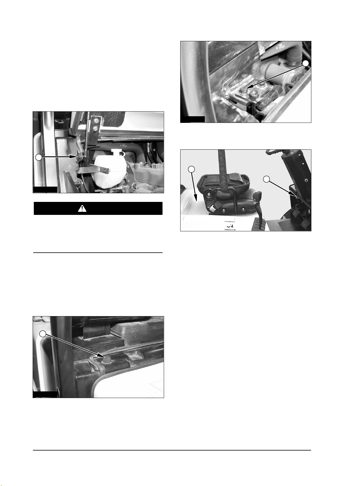
The hood and seat assembly can fall when nut (1)
is removed from the support cylinder rod. To avoid
personal injury, support the seat and hood
assembly before removing nut (1).
1. Raise the hood. Support the hood with a hoist.
2. Remove nut (1) from the support cylinder. Remove
the cylinder rod from the bracket.
3. Lower the hood.
4. Remove the bolts (2) from the cover. Remove
cover.
5. Remove the washers and four bolts (3).
6. Release latch (5). Use the hoist to remove hood
and seat assembly (4). The hood and seat
assembly weighs 52 kg (115 lb).
7. Install the hood and seat assembly in the reverse
order of removal.
IACD201P
IACD202P
IDCD054P
IACD203P
1
3
5
4
2
WARNING
Vehicle Systems Disassembly & Assembly
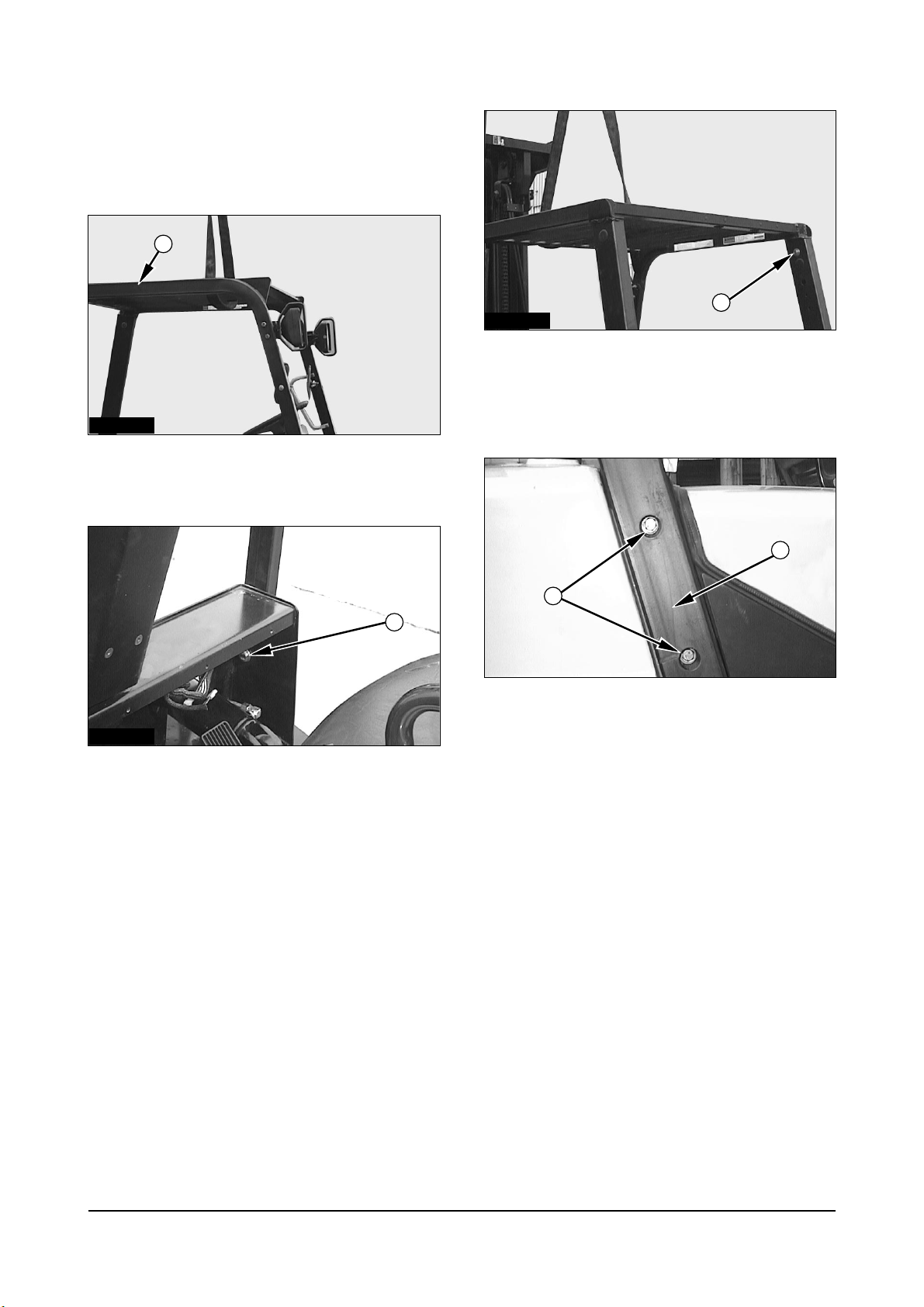
Overhead Guard
Remove & Install Overhead Guard
1. Support overhead guard (1) with lifting straps and
a hoist.
2. Remove the washers, nuts, and two bolts (2).
3. Remove the washers, nuts, and two bolts (3).
4. Remove front overhead guard (1), Front overhead
guard (1) weighs 30 kg (66 lb).
5. Remove the washers, nuts, and four bolts (4).
6. Remove rear Leg (5).
7. Install front overhead guard (1) and rear leg (5) in
the reverse order of removal.
6
IDCD055P
IDCD056P
IDCD057P
IDCD058P
1
3
4
5
2
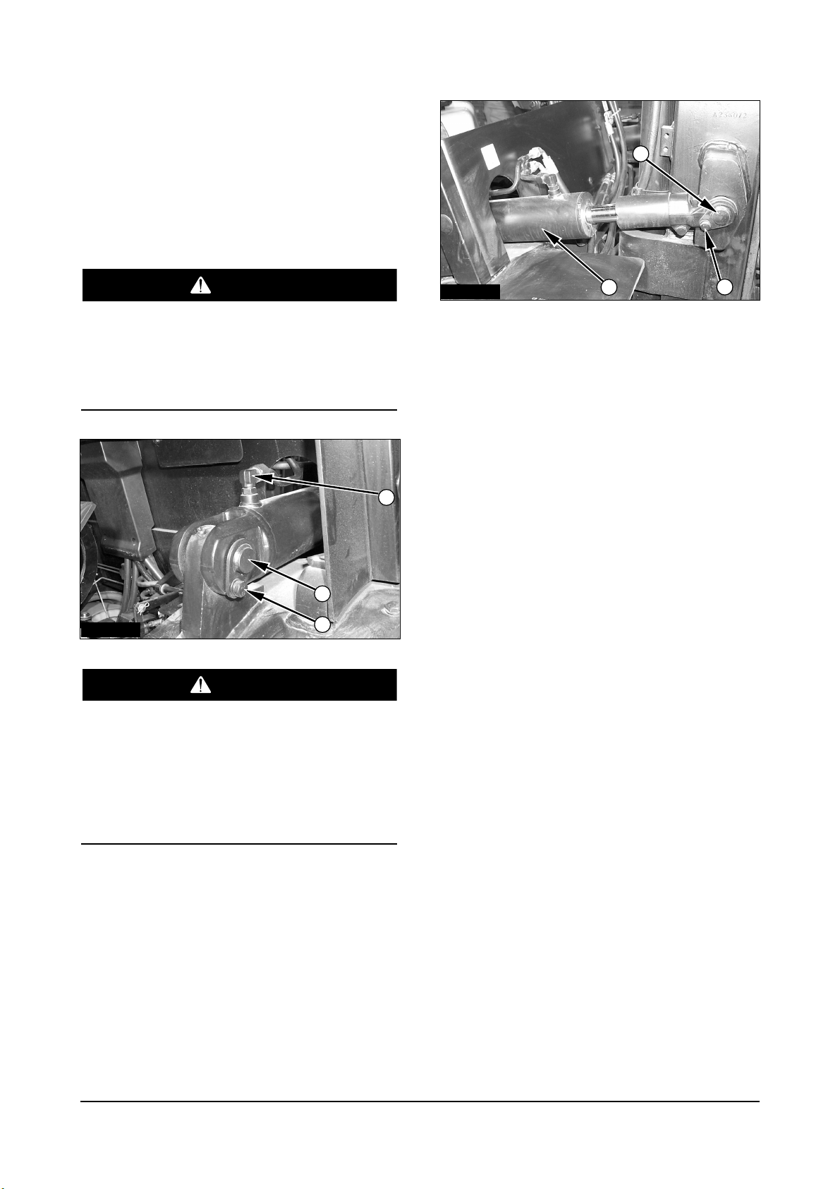
Vehicle Systems Disassembly & Assembly
Tilt Cylinders
Remove & Install Tilt Cylinders
NOTE : The procedure for removing and installing
the tilt cylinders is the same for both cylinders.
If both tilt cylinders are removed at the same time
the mast can fall. To avoid possible personal
injury, make sure the mast is securely held in
place or supported by a hoist before removing the
tilt cylinders.
To prevent personal injury, move the control
levers backward and forward to release any
pressure in hydraulic system. Slowly loosen the
cap of the hydraulic tank to release any pressure
in the tank. Be cautious of hot hydraulic oil when
any lines are disconnected in the hydraulic
system.
1. Disconnect elbow (2). Remove retainer bolt (3)
and pin (1).
2. Remove retainer bolt (6) from pin (5). Remove pin
(5).
3. Remove tilt cylinder (4).
4. Install the tilt cylinder in the reverse order of
removal.
7
IACD204P
IACD205P
2
6
5
4
3
1
WARNING
WARNING
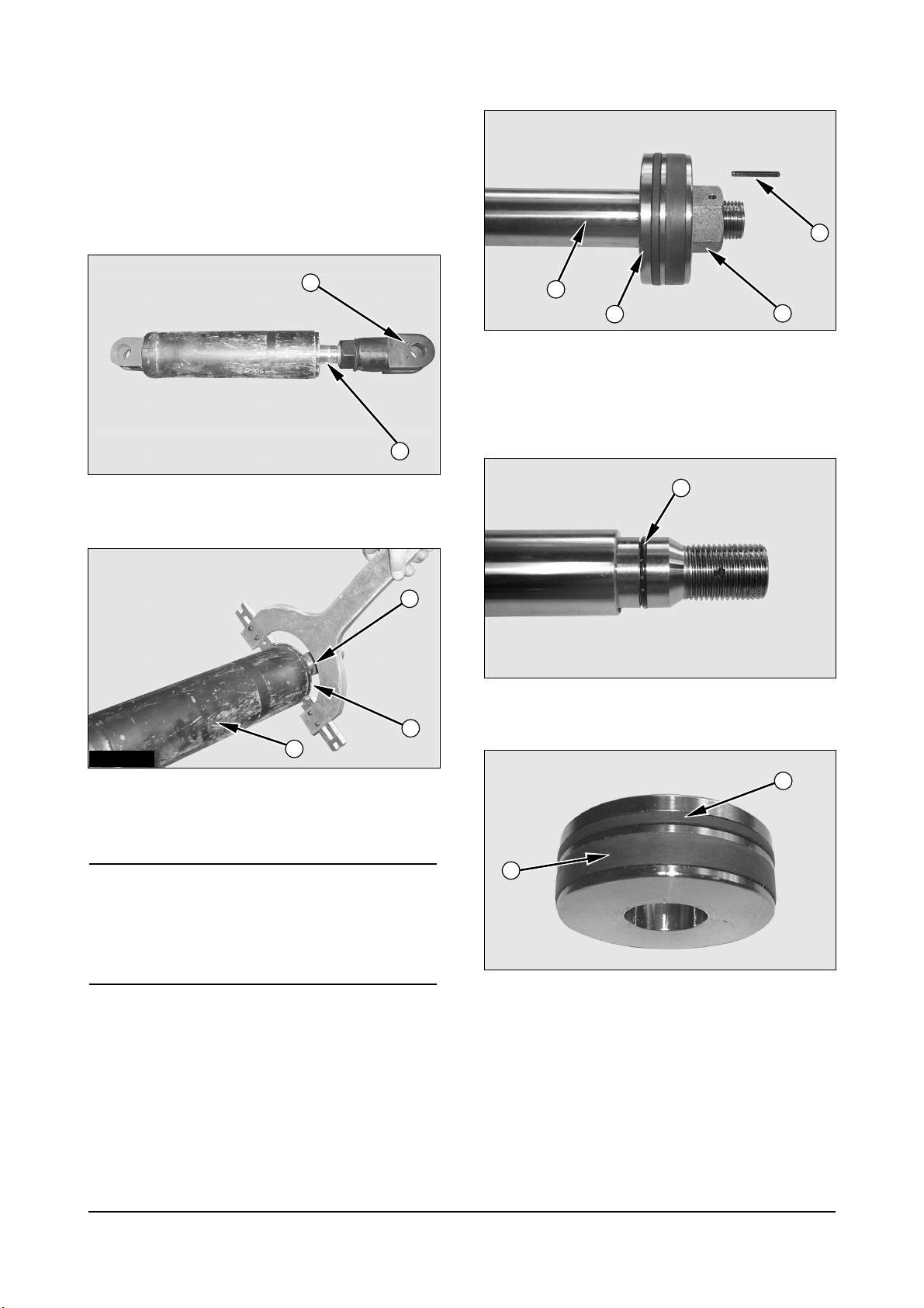
Vehicle Systems Disassembly & Assembly
Disassemble & Assemble Tilt
Cylinders
Start By:
a. Remove tilt cylinder.
1. Remove eye (1) from the rod assembly (4).
2. Remove rod cover (2) from the cylinder tube (3)
using a spanner wrench.
NOTICE
Use extra care not to damage the highly finished
surface of the cylinder rod and the bore of the clylinder
tube during disassembly and assembly of the tilt
cylinder.
3. Remove rod assembly (4) from the cylinder body.
4. Remove pin (5) inside hole and nut (6) from the
cylinder rod (4).
5. Remove piston (7) from the cylinder rod.
6. Remove O-ring seal (8) from the cylinder rod.
7. Remove wear ring (9) and slipper seal (10) from
the piston.
8
ICCD002P
ICCD003P
ICCD005P
ICCD006P
ICCD004P
1
4
4
8
10
9
2
3
4
7
6
5
Vehicle Systems Disassembly & Assembly
8. Remove O-ring seal (11) and backup ring (12)
from the rod cover (2).
9. Remove wiper seal (13), backup ring (14), U-
packing (15) and DU-bush (16) from the rod cover.
NOTE : Assemble the tilt cylinder in the reverse
order of disassembly.
Secondary Lift Cylinders
Disassemble Secondary Lift
Cylinders
Start By :
a. Remove secondary lift cylinders.
1. Put secondary lift cylinder (1) in position as shown.
2. Remove head assembly (2) with tool.
9
ICCD007P
ICCD008P
11
2
12
13
16
15
14
Vehicle Systems Disassembly & Assembly
3. Remove rod (3) from the cylinder body.
4. Remove retaining ring (4) and piston (5) from the
cylinder rod.
5. Remove O-ring seal (6) from the cylinder rod.
6. Remove O-ring seal (7), back-up ring (8) and seal
(9) from the piston.
7. Remove O-ring seal (10) from the head assembly.
8. Remove wiper seal (11), seal (12) and bush (13)
from the head assembly.
10
Vehicle Systems Disassembly & Assembly
Assemble Secondary Lift
Cylinders
1. Install bush (13) and seal (12).
2. Install wiper seal (11). Install the seal with the lip
toward the outside.
3. Install O-ring seal (10) onto the head assembly.
4. Install seal (9), back-up ring (8) and O-ring seal (7)
on the piston.
5. Install O-ring seal (6) on the cylinder rod.
6. Install piston (5) and retaining ring (4) on the
cylinder rod.
7. Install cylinder rod (3) in the cylinder body.
11
Vehicle Systems Disassembly & Assembly
8. Install head assembly (2) on the cylinder rod and
tighten using tool.
End By :
a. Install secondary lift cylinders.
Primary Lift Cylinder
Remove & Install Primary Lift
Cylinder
Start By :
a. Remove carriage.
To prevent personal injury, move the control
levers backward and forward to release any
pressure in hydraulic system. Slowly loosen the
cap of the hydraulic tank to release any pressure
in the tank. Be cautious of hot hydraulic oil when
any lines are disconnected in the hydraulic
system.
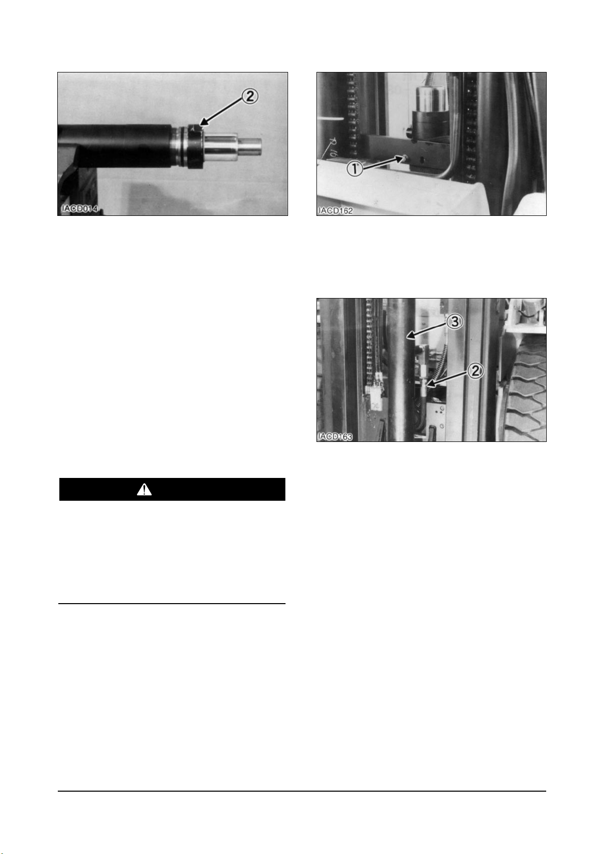
1. Fasten nylon straps and hoist to the primary lift
cylinder.
2. Remove bolt (1).
3. Pull the cylinder out far enough to disconnect
hydraulic hose (2). Remove primary lift cylinder
(3).
4. Install primary lift cylinder (3) in the reverse order
of removal.
End By :
a. Install carriage.
12
WARNING

Vehicle Systems Disassembly & Assembly
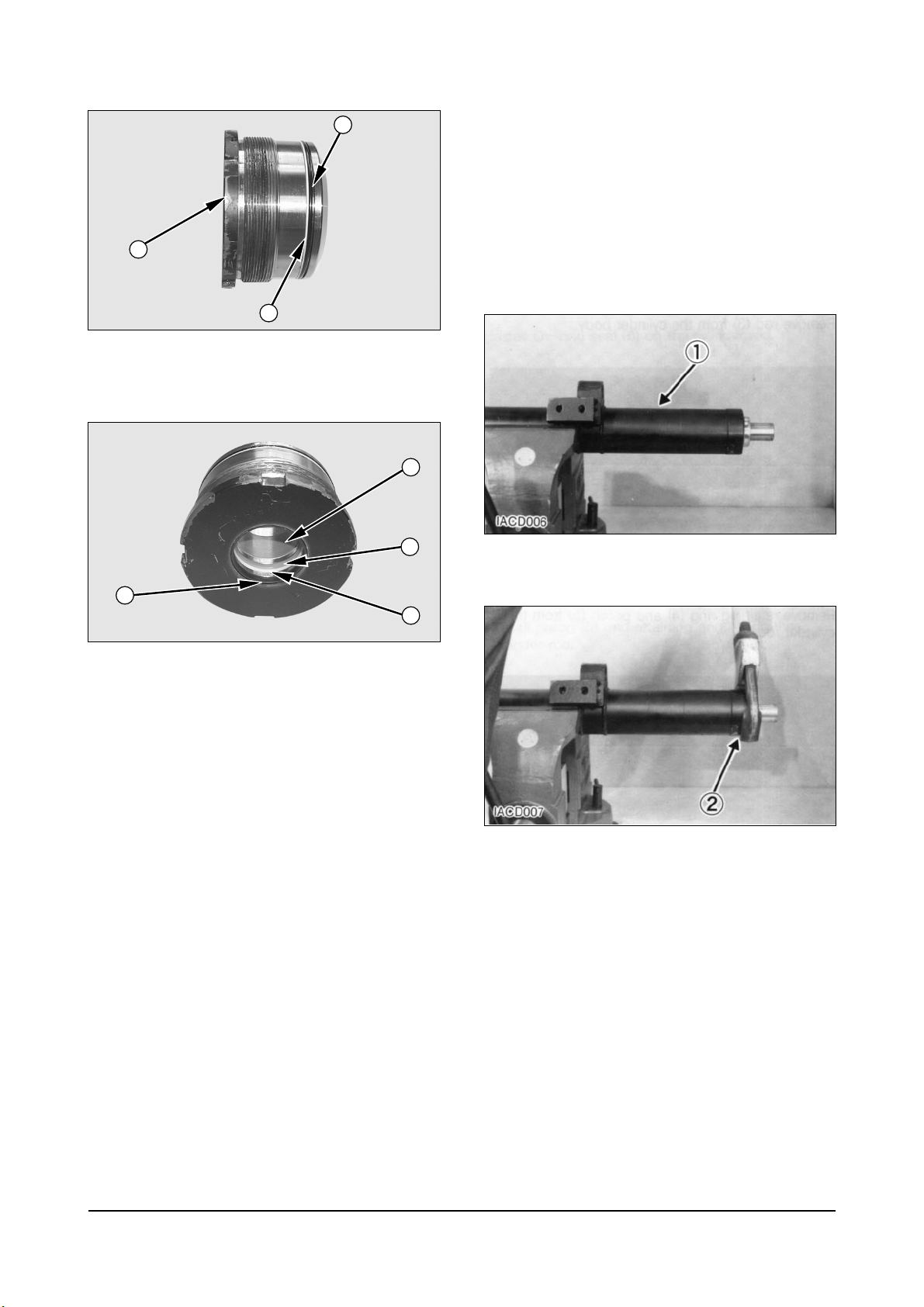
Disassemble Primary Lift Cylinder
Start By :
a. Remove primary lift cylinder.
1. Remove bearing (1).
2. Remove rod (2) from the cylinder body.
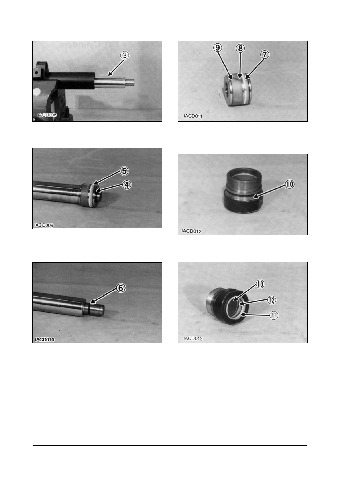
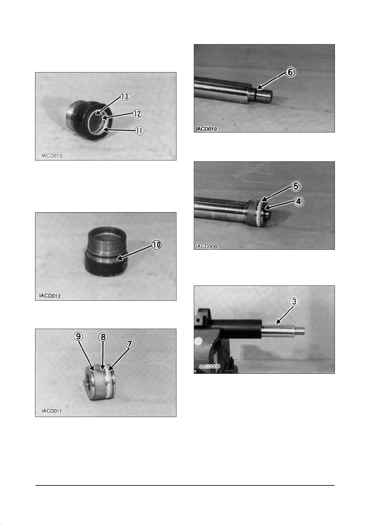
3. Remove split rings (3) from the cylinder rod.
4. Remove O-ring seal (4) and back-up ring (5) from
the bearing.
5. Remove wiper seal (6), back-up ring (7), seal (8)
and rings (9) from the bearing.
13

Vehicle Systems Disassembly & Assembly
Assemble Primary Lift Cylinder
1. Install back-up ring (7) and seal (8) in the bearing.
Install the seal with the lip toward the inside.
2. Install wiper seal (6). Install the seal with the lip
toward the outside.
3. Install rings (9) in the bearing.
NOTE : Install the back-up ring with the curved side
contacting the O-ring seal.
4. Install the back-up ring (5) and O-ring seal (4) on
the bearing.
5. Install split rings (3) on the cylinder.
6. Install cylinder rod (2) in the cylinder body.
7. Install bearing (1) on the cylinder body. Tighten the
bearing (1).
End By :
a. Install primary lift cylinder.
14

Vehicle Systems Disassembly & Assembly
Steering Wheel
Remove & Install Steering Wheel
1. Remove cap (1) from the steering wheel.
2. Remove nut (2) and cup (3) from the steering
wheel shaft. Put location marks on the steering
wheel and the steering wheel shaft for installation
purposes.
3. Use hammer (A) to remove the steering wheel
from the shaft.
NOTE : Use the following steps to install the steering
wheel.
4. Put the steering wheel on the steering wheel shaft
in its original position.
5. Install cup (3) and nut (2). Tighten nut (2) to a
torque of 80
L 7 N¥m (60 L 5 lb¥ft).
6. Install cap (1).
Steering Unit
Remove & Install Steering Unit
Start By:
a. Remove steering wheel.
1. Open the access cover for the fuse panel.
Remove horn switch and open the top cover.
2. Loosen two bolts (1). Slide directional control
switch (3) off of steering column (2). Set switch (3)
aside, clear of the steering column.
15
IACD208P
IACD206P
IACD209P
IDCD064P
1
2
1
323
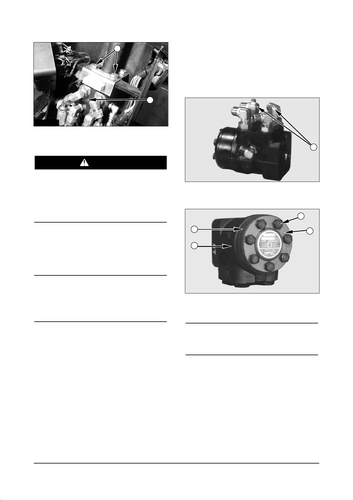
3. Remove two bolts (4).
To prevent personal injury be sure pressure in the
hydraulic system has been released before
disconnecting any hydraulic lines. Slowly loosen
the cap of the hydraulic tank to release any pressure
in the tank. Be cautious of hot hydraulic oil when
any lines are disconnected in the hydraulic system.
NOTE : Identify and mark all hydraulic hoses for
purposes of reassembly.
4. Disconnect five hoses from steering unit (5).
NOTICE
Steering unit (5) and column (2) can separate after
bolts (4) have all been removed, causing unit (5) to
fall. To avoid damaging components, support the
steering pump while removing bolts (4).
5. Support steering unit (5) while removing the
remaining two bolts (4). Remove steering unit (5)
and steering column (2).
6. Install the steering unit in the reverse order of
removal.
End By :
a. Install steering wheel.
Disassemble & Assemble Steering
Unit
Start By :
a. Remove steering unit from the truck.
1. Remove the elbows (1) from the body.
2. Remove seven bolts (5) from gerotor housing (3).
NOTICE
Make a note of the position of special bolt with a pin.
It is located at a mark in line with check valve.
3. Separate housing (3) and cap (4) from steering
unit body (2).
Vehicle Systems Disassembly & Assembly16
ICCD079P
ICCD080P
1
5
3
2
4
IACD210P
4
5
WARNING

Vehicle Systems Disassembly & Assembly
4. Remove the components from housing (3) as
follows:
a. Remove plate (6) from housing (3).
b. Remove shaft (7) from gerotor (9).
c. Remove gerotor (9) from housing (3).
d. Remove O-rings seal (8) from housing (3).
e. Remove O-ring seal (10) from cap (4).
5. Remove suction valve balls (12) and pins (11).
6. Remove screw (13) and check valve ball (14).
7. Remove O-ring seal (15) from steering unit body
(2).
8. Remove sleeve (16) from the body.
9. Remove the components from sleeve (16) as
follows :
a. Remove pin (18) from spool (17) and sleeve
(16).
b. Remove spool (17) from sleeve (16).
c. Remove two bearing races (19), (20) and
bearing (21) from spool (17).
d. Remove six springs (23) and ring (22) from
spool (17).
10. Remove O-ring seal (24) and king-ring (25) from
body.
11. Check the condition of dust seal ring(26).
Replace seals with new if worn or damaged.
17
ICCD081P
ICCD082P
ICCD083P
ICCD086P
ICCD084P
ICCD085P
976
10
17
16
23
17
22
21
19
4
12
14
11
2
16
252624
15
13
3
8
18
23
20

Vehicle Systems Disassembly & Assembly
12. Remove plug (27) and washer (28) from steering
unit body.
13. Remove plug (31) and spring (32) from the body
(2).
14. Remove poppet (34) and relief valve housing (35)
from the body.
15. Remove plug (36) and washer (37) from the
body.
NOTE : The following steps are for assembling the
steering pump.
16. Install washer (37) and plug (36) into the steering
unit body.
17. Install housing (35) and poppet (34) into the
pump body.
18. Install spring (32) and plug (31) into body (2).
Tighten plug (31) to a torque 50 N¥m (37 lb¥ft).
19. Install washer (28) and plug (27) into body (2).
Tighten plugs to a torque 30 N¥m (22 lb¥ft).
18
ICCD087P
ICCD088P
ICCD089P
27
2
35
32
31
34
ICCD088P
2
35
32
31
34
28
ICCD087P
27
28
36
37
ICCD089P
36
37

Vehicle Systems Disassembly & Assembly
20. Install dust seal ring (26). Install O-ring seal (24)
with king-ring (25) into body.
NOTICE
For purposes of installation, note that springs (23) are
installed in two stacks of three. Make sure the curves
of the two stacks are in contact and positioned in the
center of spool (17). The notched side of springs (23)
must be positioned toward sleeve (16).
21. Install springs (23) into spool (17).
22. Install spool (17) into sleeve (16).
23. Install pin (18), ring (22), two bearing races (19),
(20) and bearing (21) in their original positions on
spool (17).
24. Install sleeve (16) into steering unit body (2).
25. Install O-ring seal (15) into body (2).
26. Install check valve ball (14) and screw (13).
Tighten the screw (13).
27. Install suction valve balls (12) and pins (11) in
their original positions into the steering unit body.
19
ICCD086P
252624
ICCD085P
17
22
21
191823
20
ICCD084P
16
23
17
ICCD082P
ICCD083P
12
14
11
2
16
15
13

Vehicle Systems Disassembly & Assembly
28. Install plate (6) onto steering unit body.
NOTICE
Make sure the notch of shaft (7) properly seats on pin
(18) when installed into body and spool (17).
29. Install shaft (7) into body (2) and spool (17).
NOTICE
Gerotor (9) must be aligned with shaft (7) and pin (18)
as shown in the illustration.
30. Install O-ring seal (8) and housing (3).
31. Install O-ring seal (10) and cap (4).
NOTICE
To assure proper operation of the steering unit, make
sure bolts (5) are clean and dry before installing.
Tighten bolts (5) in the sequence shown in the
illustration.
32. Install bolts (5) into cap (4). Tighten bolts (5) in
correct sequence to a torque of 30 L 6 N¥m (22
L 4.4 lb¥ft).
End by :
a. Install steering unit to the truck.
20
ICCD090P ICCD091P
ICCD081P
976
10
4
3
8
2
4
6
7
5
3
1
ICCD080P
5
3
2
4

Vehicle Systems Disassembly & Assembly
Brake Hydraulic Booster
Remove And Install Brake Hydraulic
Booster
1. Remove the floor plate over the brake hydraulic
booster.
2. Disconnect pressure line (3).
3. Disconnect return line (4) and supplement line (1).
4. Disconnect brake line (5).
5. Remove pin (6) and bolts (7).
6. Remove hydraulic booster (2).
NOTE : The following steps are for installation of the
brake master cylinder.
NOTE : Installation is reverse order of removal.
7. Remove the air (bleed the brake lines). See the
topic Brake System Air Removal in Testing And
Adjusting.
8. Install the floor plate over the brake master
cylinder.
Tie Rods
Remove And Install Tie Rods
Start By :
a. Remove steer wheels.
NOTE : The procedure to remove and install the tie
rod is the same for each steer wheel.
1. Support the steer axle with a floor jack (A).
Position the wheel to gain access to the tie rods.
2. Remove two pin retaining bolts (2). Remove pins (1).
3. Remove tie rod (4) and dust seals (3).
4. Use tooling (B) to remove bearings (5) from the tie rod.
5. Use tooling (B) to install new bearings (5) in the tie rod.
6. Install the tie rod in the reverse order of removal.
Tools Needed A B
Floor Jack 1
Drive Set 2
21
IACD211P
3
2
7
615
4
IACD212P
1
3
4
2
IACD213P
5

Vehicle Systems Disassembly & Assembly
Steering Knuckles, Kingpins,
And Bearings
Remove And Install Steering
Knuckles, King Pins And Bearings
Start By:
a. remove steer wheels
NOTE : The procedure to remove and install the
steering knuckles, kingpins, and bearings is the same
for both sides of the lift truck.
1. Remove pin retaining bolt (2). Remove pin (1).
2. Position the tie rod away from the steering
knuckle.
3. Remove four bolts (3) and cover (4).
4. Remove four bolts (5) and cover (6).
5. Remove the nut and bolt (7). For the purpose of
reassembly, the torque for bolt (7) is 11 L 1 N¥m
(8 L 1 lb¥ft).
Tools Needed A
Drive Set 1
22
IACD215P
5
IACD216P
7
6
IACD214P
3
4
IACD212P
1
2

Vehicle Systems Disassembly & Assembly
6. Remove kingpin (8) and knuckle (9).
7. Remove spacer (11), bearing cup (13) and bearing
cone (12).
8. Check the condition of lip type seal (10). Replace
seal (10) with new if worn or damaged.
9. Repeat steps 7 and 8 for the remaining seal,
bearing and spacer in the other side of knuckle
(9).
NOTICE
Check the condition of all seals, bearings and
components. If any parts are worn or damaged use
new parts for replacement.
10. Lubricate the pins, king pins and bearings.
11. Install the steering knuckle, kingpins and bearings
in the reverse order of removal.
End By:
a. Install steer wheels.
Steer Axle
Remove & Install Steer Axle
Be sure the pressure in the hydraulic system is
released before any lines or hoses have been
disconnected.
1. Put the lift truck in position on tooling (A).
2. For the purpose of reassembly, put identification
marks on hoses (1). Disconnect hoses (1). Plug
and cap all openings to prevent contamination and
debris from entering the system.
3. Support the steer axle with a floor jack.
4. Loosen mounting bolts (2) until approximately two
bolt threads are left in the mounting bosses.
5. Lower the steer axle onto the bolt heads with the
floor jack
Tools Needed A
Jack Stand 4
23
IACD217P
9
IDCD081P
9
IACD218P
1
IACD219P
4
2
3
10
131211
8
WARNING

Vehicle Systems Disassembly & Assembly
6. Remove bolts (2) and mounting caps (3) from the
steer axle.
7. Remove steer axle (4). The steer axle weighs180
kg (400 lb).
NOTE : Use the following steps to install the steer
axle.
8. Use a floor jack to position steer axle (4).
NOTE : Use bolts (2) and cap (3) to align steer axle
(4) with the mounting bosses while raising steer axle
(4) into position with the floor jack.
9. Seat steer axle (4) as follows:
a. Install bolts (2) through cap (3) and into the
mounting bosses approximately two bolt
threads.
b. Use the floor jack to raise steer axle (4) into the
mounting boss.
c. Tighten bolts (2).
11. Connect hoses (1).
Steering Cylinder
Remove & Install Steering Cylinder
1. Remove the pin retaining bolt (4) and pin (2) from
the tie rod at each end of steering cylinder (1).
2. Disconnect two hoses (5).
3. Remove four bolts (3). For installation purposes,
the torque for bolts (3) is 240 LL30 N¥m (178 LL22
lb¥ft).
4. Remove steering cylinder (1).
5. Install steering cylinder (1) in the reverse order of
removal.
24
IACD218P
1
IACD219P
4
2
3
IACD212P
2
4
1
IACD218P
3
5

Vehicle Systems Disassembly & Assembly
Disassemble And Assemble
Steering Cylinder
Start By :
a. Remove steering cylinder.
1. Put the steering cylinder in position in a vise.
2. Loosen head (1) from tube (2) with a spanner
wrench.
3. Remove rod assembly (3) from the tube (2).
4. Remove retaining ring (5) with a plier and ring (6)
from each side of piston (7) that holds piston in
position on rod (3).
5. Remove piston (7) from the rod (3).
6. Remove O-ring seal (8) from the rod.
7. Remove seal ring (9) and backup seal (10) from
the piston.
8. Loosen the head in the opposite end of the tube.
25
ICCD065P
1
2
ICCD066P
2
3
ICCD066P
2
3
ICCD068P
563
7
ICCD069P
8
ICCD070P
10
9

Vehicle Systems Disassembly & Assembly
9. Remove O-ring seal (12) and backup ring (13)
from each head (1).
10. Remove wiper seal (14), backup ring (15), U-
packing (16) and DU-bush (17) from the bore of
each head.
NOTE : Assemble the steering cylinder in the reverse
order of disassembly.
Tires And Rims (Steer)
Remove And Install Tires And Rims
(Steer)
1. Put a hydraulic jack in position under the steer
axle.
2. Loosen nuts (1) that hold the tire and rim in place.
3. Lift the steer axle until the tire is clear of the
ground. Remove nuts (1). Remove the tire and
rim.
NOTE : The following steps are for installation of the
tires and rims (steer).
4. Put the tire and rim in position on the hub.
5. Install nuts (1) that hold the tire and rim in place.
Tighten the nuts to a torque of 430 L 35 NIIm
(318 LL25 lbIIft).
6. Lower the steer axle and remove the hydraulic
jack.
26
ICCD094P
1
13
12
ICCD095P
17
16
15
14
IA3M4014
1

Hydraulic Control Valves
Remove And Install Hydraulic
Control Valves
Hydraulic oil under pressure can remain in the
hydraulic system after the engine and pump have
been stopped. Personal injury can result if the
pressure is not released before any work is done
to the hydraulic system. To prevent possible
personal injury, turn the engine off and move the
control levers to make sure the hydraulic pressure
is released before any fitting, plug, hose or
component is loosened, tightened, removed or
adjusted. Always move the lift truck to a clean and
level location away from the travel of other
machines.
NOTE : For purposes of reassembly, put
identification marks on all lines, tubes and hoses
before any disconnections are made.
1. Disconnect hydraulic lines (2) from control valve
(1).
2. Remove the cotter pins, washers and pins from
linkages.
3. Support control valve (1). Remove circuit braker
plate (4). Remove three bolts (3), nut and control
valve (1).
4. Install the control valve in the reverse order of
removal.
5. Fill the hydraulic tank to the correct level with fluid.
Refer to the Operation And Maintenance Manual
for further information.
Vehicle Systems Disassembly & Assembly27
IACD221P
1
2
IACD222P
3
1
4
WARNING

Vehicle Systems Disassembly & Assembly
Disassemble Hydraulic Control
Valve
Start By :
a. Remove hydraulic control valve.
NOTE : For purpose of assembly, put identification
marks on all valve sections.
1. Remove three nuts (1) to separate the valve
sections.
2. Remove inlet section assembly (2) from the valve
body.
3. Remove O-ring (3) from inlet section assembly (2).
4. Remove relief valve (4) and O-ring (5).
5. Remove lift section assembly (6) from the valve
body.
6. Remove plug (7) and O-ring (8) from the lift
section assembly (6).
7. Remove O-ring (9), poppet (10) and spring (11)
from the lift section assembly (6).
8. Remove two screws (12) and cap (13) from lift
section assembly.
28
IACD223P
IACD224P
1
2
2
543
IACD225P
6
IACD226P
IACD227P
7
6
9
11
10813
12

Vehicle Systems Disassembly & Assembly
9. Remove relief valve (14) and O-ring (15) from lift
section assembly.
10. Remove two screws (16) and seal plate (17).
11. Remove lift spool (18).
12. Remove the wiper seals (19) and O-rings (20)
from the spool. Check the condition of O-rings
and wiper seals and replace with new ones if
needed.
NOTE : Remove the spool end (21) from the spool
with a wrench. The centering spring (22) has a slight
preload and will extend to its free length when the
spool end is removed.
13. Remove the spring seats (23 and 24), centering
spring (22) and seal plate (25).
14. Remove tilt section assembly (26) from the valve
body.
15. Remove O-ring (27), poppet (28) and spring (29)
from tilt section assembly (26).
16. Remove two screws (30) and cap (31) from tilt
section assembly.
29
IACD229P
20
25
22
21
232419
IACD228P
IACD231P
IACD232P
18
17
15
14
16
282930
31
27
26
IACD230P
26

Vehicle Systems Disassembly & Assembly
17. Remove two screws (32) and seal plate (33).
18. Remove tilt spool (34).
19. Remove the wiper seals (35) and O-rings (36).
Check the condition of wiper seals and O-rings
and replace with new ones if needed.
NOTE : Remove the spool end (37) from the spool.
The centering spring (38) has a slight preload and
will extend to its free length when the spool end is
removed.
20. Remove spring seats (39 and 40), spring (38 and
42) and piston (41).
21. Remove side shift section assembly (43) and
fourth section (44) from the valve body.
NOTE : Do step 7 through 13 except step 9 to
disassemble valve spools of side shift and fourth
section assembly.
30
IACD234P
IACD233P
IACD236P
IACD235P
41
42
33
36
34
32
373835
37
39
384043
44

Vehicle Systems Disassembly & Assembly
Assemble Hydraulic Control Valve
NOTICE
Do not use caustic (corrosive) materials to clean any
parts in this valve group. Caustic materials will cause
corrosion and damage to parts.
1. Make sure all valve parts are clean and free of dirt.
2. Install O-ring (3) to inlet section assembly (2).
3. Install relief valve (4) with O-ring (5) to inlet section
assembly (2). The torque for the relief valve is
65 N¥m (575 lb¥in).
4. Install the spring seats (23 and 24), centering
spring (22) and seal plate (25) on the lift spool.
5.
Compress the spring with spool end (21) and
tighten spool end. Torque the spool end to 8 ~
11 N
¥
m (70 ~ 97 lb¥in).
6. Install the wiper seals (19) and O-ring (20) to the
spool (18).
7. Install the spool (18), seal plate (17) and the
screws (16).
8. Install relief valve (14) with O-ring (15) to lift
section assembly. The torque for the relief valve is
45 N¥m (398 lb¥in).
31
IACD224P
2
543
IACD229P
20
25
22
21
232419
IACD228P
18
17
15
14
16

Vehicle Systems Disassembly & Assembly
9. Install cap (13) and two screws (12).
10. Install O-ring (9), poppet (10) and spring (11) to
lift section assembly (6).
11. Install O-ring (8) and plug (7) to the lift section
assembly.
12. Install piston (41), spring (42), spring seats (39
and 40) and spring (38) on the tilt spool assembly.
13. Compress the spring with spool end (37).
Torque the spool end to 8 ~ 11 N¥m (70 ~ 97 lb¥in).
NOTE : Do step 6, 7, 9 and 10 to assemble the tilt
spool to the tilt section assembly.
NOTE : Do same steps to assemble the side shift
section and fourth section assembly.
14. Assemble all the sections on the studs.
15. Install the nuts (1) that hold the valve sections
together.
Tighten the single top nut to torque of 100 N¥m
(885 lb¥in) and two bottom nuts to torque of
65 N¥m (575 lb¥in).
End By :
a. Install hydraulic control valve.
32
IACD226P
IACD227P
7
6
9
11
10813
12
IACD235P
41
42
37
39
38
40
IACD223P
1

Vehicle Systems Disassembly & Assembly
Hydraulic Pump
Remove and Install Hydraulic Pump
Start By :
a. Remove counterweight.
1. Drain the oil from the hydraulic tank.
2. Disconnect three oil lines (1) from the pump
elbows.
3. Remove bolts (2) and disconnect U-Joint (3).
4. Fasten a hoist to pump (5). Remove bolts (4) that
hold the pump in place. Remove the pump and
plate assembly. The weight of the pump is 30 kg
(132 lb).
NOTE : The following steps are for installation of the
hydraulic pump.
5. Inspect seals for damage. Install new seals, if
needed.
6. Fasten a hoist to pump (5). Put the pump and
plate assembly in position and install the bolts that
hold the pump in place. The weight of the pump is
30 kg (132 lb).
7. Connect three oil lines (1) to the pump elbows.
8. Connect U-joint (3) in position and install bolts (2).
9. Fill the hydraulic tank with oil to the correct level.
See the Operation and Maintenance Manual.
End By :
a. Install counterweight
33
IACD237P
IACD238P
1
5
4
2
3

Vehicle Systems Disassembly & Assembly
Disassemble And Assemble
Hydraulic Pump
1. Position the pump vertically in the vise with the
drive shaft facing down, and tighten the vise. Do
not over-tighten. Take care to avoid damaging
machined surfaces. Make a reference mark
vertically down the pump to enable you to
reassemble the pump sections in the same
position.
2. Use a wrench to remove four screws (1).
3. Remove the cover (2). Take care not to damage
precision machined surfaces.
4. Remove the bush (3) and examine it carefully.
Replace if damaged.
5. Remove seal (4) and backup seal (5) from the
bush.
6. Remove O-ring (6) from the body (7).
7. Carefully remove the drive gear (8) and idler gear
(9). Take great care not to strike the shafts against
hard surfaces which could damage the gear teeth.
8. Remove the pump body (7). Take care not to
damage precision machined surfaces. Carefully
examine all components. Replace any damaged or
worn ones.
34
IACD239P
IACD240P
IACD241P
IACD242P
IACD243P
IACD244P
1
2
5
7
4
369
8
7

Vehicle Systems Disassembly & Assembly
9. Remove the spacer (10).
10. Remove splined coupling (11) and O-rings (12).
11. Remove four nuts (13) with a spanner.
12. Remove the body (14). If necessary insert two
screwdrivers in the recesses and lever upwards.
Take care not to damage precision machined
surfaces.
13. Remove balance plate (15), seal (16), backup
seal (17), drive gear (18) and idler gear (19) from
the body (14). Take great care not to strike the
shafts against hard surfaces which could damage
the gear teeth.
14. Remove the balance plate (20) and seals from
the body.
35
IACD245P
IACD246P
IACD247P
IACD248P
IACD249P
IACD250P
10
14
12
15
16
17
14
19
18
13
20
11

Vehicle Systems Disassembly & Assembly
15. Remove O-ring (21) from the flange (22).
16. Remove the flange (22) from the vise.
17. Assemble the hydraulic pump in the reverse
order of disassembly.
Counterweight
Remove And Install Counterweight
1. Install two eyebolts in the counterweight. Fasten a
hoist to the eyebolts as shown.
2. Remove two bolts (1), washers that hold the
counterweight to the frame. Remove the
counterweight. The weights of the different
counterweight go from a minimum of 1650 kg
(3630 lb) to a maximum of 2350 kg (5170 lb).
NOTE : The following steps are for installation of the
counterweight.
3. Install two eyebolts in the counterweight. Fasten a
hoist to the eyebolts.
4. Put the counterweight in position on the frame and
install bolts (1), washers that hold the
counterweight in place. Tighten torque : 600 LL50
N¥m (442 LL37 lb¥ft).
36
IACD251P
IACD252P
IACD253P
22
21
1

Vehicle Systems Disassembly & Assembly
Hydraulic Oil Filter Assembly
Remove And Install Hydraulic Oil
Filter Assembly
1. Disconnect four oil lines (1).
2. Remove hydraulic tank cover (2).
3. Remove the oil filter from hydraulic tank cover.
NOTE : The following steps are for installation of the
hydraulic oil filter assembly.
4. Install the hydraulic oil filter assembly in position
on hydraulic tank cover.
5. Install the hydraulic tank cover (2) with six bolts
and washers.
6. Connect four oil lines (1).
7. Fill hydraulic oil tank to the correct level. See the
Operation and Maintenance Manual.
Transaxle
Remove & Install Transaxle
Start By :
a. Remove mast *
b. Remove floor plate
* Refer to the mast systems Disassembly &
Assembly section for further information.
1. Raise the machine until tires are approximately 1
to 2 inches off of the floor. Position the machine on
tooling (A).
NOTE : Put identification marks on all wiring, hoses
and lines to assure proper installation.
2. Disconnect hoses (1) and brake tubes (2).
Loosen bolts (3) and remove pedal assembly (4).
37
IACD222P
IACD255P
2
1
1
2
3
4
Tools Needed A B
Stand 2
Link Bracket 1

Vehicle Systems Disassembly & Assembly
3. Remove cover (5).
4. Remove cowl plate (6). Disconnect brake tubes (7)
and parking cables from drive axle.
5. Disconnect accel cable (8).
6. Disconnect wires (9) from solenoid valves and wire
from transmission temperature sender.
7. Disconnect two cooling hoses (10).
8. Loosen bolts (11) and remove drive axle mounting
bracket (12).
9. Support the engine with a hoist and tooling (B).
10. Support transaxle assembly with a floor jack and
wood block.
11. Remove housing cover.
Remove bolts (13) that hold the converter to the
flywheel.
NOTE : At this point, make a final check to be sure
all removals and disconnections have been made
from the transaxle.
12. Remove bolts (14) and nuts from the converter
housing.
13. Use the floor jack to move transaxle assembly
from beneath the machine.
14. Install transaxle in the reverse order of removal.
15. Bleed the brake system.
Refer to the topic ÒBrake System Air removalÓ in
the Testing and Adjusting section of Vehicle
Systems.
16. Fill all fluids to their correct levels.
38
IACD259P
IACD257P
7
11
12
6
IACD258P
9
8
10
IACD260P
14
13
IACD256P
5

Vehicle Systems Disassembly & Assembly
End By :
a. Install floor plate.
b. Install mast *
* Refer to the Mast System Disassembly & Assembly
Section for further information
Engine
Remove & Install Engine
NOTE : Procedures for LP gas and diesel engines
are all similar. The engine shown in the following
illustrations is for diesel engine.
Start By :
a. Remove overhead guard *
b. Remove hood (with seat) assembly *
c. Remove counterweight *
d. Remove floor plate.
e. Remove hydraulic control valve *
* Refer to the topics ÒOverhead GuardÓ, ÒHood (with
seat) AssemblyÓ, ÒCounterweightÓ and ÒHydraulic
Control ValveÓ in this module.
1. Disconnect all hoses from radiator (3). Loosen
bolts (1) and (2) and remove radiator (3).
2. Disconnect air intake hose (4).
3. Disconnect battery cables and remove battery (5)
and battery tray assembly.
4. Disconnect fuel lines from the engine.
5. Disconnect accel cable and engine stop motor
cable from the engine.
39
Tools Needed A
Link Bracket 1
IACD262P
5
4
IACD263P
IACD261P
3
1
2

Vehicle Systems Disassembly & Assembly
6. Loosen nuts (6) and disconnect exhaust tube (7).
7. Disconnect engine wire harness (8). Disconnect
wires from the alternator (9). To remove engine
from the truck, other wires or connectors not
shown should be disconnected.
8. Remove bolts (10) and disconnect U-joint (11)
from the engine
9. Remove housing cover.
Remove bolts (12) that hold the converter to the
flywheel.
NOTE : At this point, make a final check to be sure
all removals and disconnections have been made
from the engine.
10. Support engine with a hoist and tooling (A).
Support transaxle with wood block.
11. Remove bolts (13) and nuts from the converter
housing.
40
IACD264P
7
6
IACD265P
8
IACD266P
9
IACD267P
IACD260P
11
131210

Vehicle Systems Disassembly & Assembly
12. Remove bolts (14) and nuts from two engine
mounts, located on each side of the engine.
NOTICE
Make sure the engine is supported underneath by
suitable wooden blocks. Failure to support engine will
result in possible damage.
13. Remove the engine with a hoist.
14. Install the engine in the reverse order of removal.
End By :
a. Install hydraulic control valve *
b. Install floor plate.
c. Install hood (with seat) assembly *
d. Install counterweight *
e. Install Overhead guard.*
* Refer to the topics ÒHydraulic Control ValveÓ, ÒHood
(with seat) AssemblyÓ, ÒCounterweightÓ and
ÒOverhead GuardÓ.
41
IACD269P
14
 Loading...