

Daewoo CP-810 Service Manual

¸¬¬°æññ-ª½ò¼©
»
ò½±
òµ®
УЯОфоррр
S/M No: CP810P-010
Service Manual
66 Cm STEREO ColourTelevision
CHASSIS : CP-810
MODEL :DTJ - 28A6F
DTJ - 28A7F
DTJ - 28B1F
DTJ - 28G6F
DTJ - 28G7F
DTJ - 28G8F
ì
Caution
: In this Manual, some parts can be changed for improving, their
performance without notice in the parts list. So, if you need the
latest parts information,please refer to PPL(Parts Price List) in
Service Information Center (http://svc.dwe.co.kr).
DAEWOO ELECTRONICS CO., LTD.

МЯЮФЫ СЪ ЭСТМЫТМН
1. Safety Instruction ........................................................................................................................ 2
2. Specifications .............................................................................................................................. 3
3. Circuit block Diagram ................................................................................................................. 5
4. Alignment Instructions ............................................................................................................... 6
5. IC Description .............................................................................................................................. 12
6. IC DC Voltage Charts .................................................................................................................. 32
7. Service Parts List/Recommendable Spare Parts List .............................................................. 35
8. Mechanical Exploded View ......................................................................................................... 45
9. Printed Circuit Board .................................................................................................................. 51
10. Schematic Diagram ..................................................................................................................... 52
1

1. Safety Instruction
WARNING
X-RAY RADIATION PRECAUTION
1. Excessive high voltage can prodece potentially hazardous X-RAY RADIATION. To avoid such hazards,
the high voltage must not exceed the specified limit.
The nominal value of the high voltage of this receiver is
23-24kv at max beam current. The high voltage must
not, under any circumstances, exceed 30kv.
Each time a receiver require servicing, the high volt-
age should be checked. It is imprortant to use an accurate and reliable high voltage meter.
: Only competent service personnel may carry out work involving the testing or repair of this equipment
2. The only source of X-RAY Radiation in this TV receiver
is the picture tube. For continued X-RAY RADIATION
protection, the replacement tube must be exactly the
same type tube as specified in the parts list.
SAFETY PRECAUTION
1. Potentials of high voltage are present when this
receiver is operating. Operation of the receiver outside
the cabinet or with the back board removed involves a
shock hazard from the receiver.
1) Servicing should not be attempted by anyone who is
not thoroughly familiar with the precautions necessary when working on high-voltage equipment.
2) Dischange the high potential of the picture tube
before handling the tube. The picture tube is highly
evacuated and if broken, glass fragments will be
violently expelled.
PRODUCT SAFETY NOTICE
Many electrical and mechanical parts in this have
special safety-related characteristics. These characteristics are often passed unnoticed by a visual
inspection and the X-RAY RADIATION protection
afforded by them cannot necessarily be obtained by
using replacement components rated for higher voltage, wattage, etc. Replacement parts which have
these special safety characteristics are identified in
this manual and its supplements, electrical compo-
2. If any Fuse in this TV receiver is blown, replace it with
the FUSE specified in the Replacement Parts List.
3. When replacing a high wattage resistor ( oxide metal
film resistor ) in circuit board, keep the resistor 10mm
away from circuit board.
4. Keep wires away from high voltage or high temperature components.
5. This receiver must operate under AC230 volts, 50Hz.
NEVER connect to DC supply or any other power or
frequency.
nents having such features are identified designated
symbol on the parts list.
Before replacing any of these components, read the
parts list in this manual carefully. The use of substitute
replacement parts which do not have the same safety
characterisitics as specifide in the parts list may create
X-RAY Radiation.
2

2. Specifications
CRT 28" : A66EAK071X54 ( PHILIPS )
System PAL/SECAM-B/G, D/K, PAL-I/I’, SECAM-L/L’, NTSC-3.58/4.43 (Play back )
Main Voltage 230V AC, 50Hz
Power Consumption Stand-by mode : 2.0 Watts
Normal operating mode : 80 Watts
Sound output 10 + 10 Watts, 10% THD at RF 60% mod. ( 1 kHz )
Speaker 12W 8ohm x 2 EA
Antenna Impedance 75 ohm unbalanced input (Din Standard )
Tuning system Frequency Synthesize(FS) Tuning System
Tuner DT5-BF14D, EL2782-105-B
Number of Program 100 programs
Aux. Terminal 21 pin EURO-SCART jack ( AV input, TV output, RGB input )
Remote controller R-22D05 with 2 "AAA" type batteries
Teletext TOP(5 Page memory) & FLOF(7 Page memory)
OSD language - West : English, German, French, Italian, Spanish, Nethelands, Swedish
21 pin EURO-SCART jack ( AV input, S-VHS input )
RCA type AV input jack
Headphone jack ( 3.5 mm )
JACK AUDIO TERMINAL (AUDIO OUT L, R)
- West option : English, German/Dutch/Flemish, French, Italian, Spanish/Portuguese,
Swedish/Finnish/Danish, Hungarian, Rumanian, Turkish
- East option : Polish, Czech/Slovak, Rumanian, Servo-croat, German/Dutch/Flemish,
French, Estonian, Lettish
- East : English, Russian, Polish, Rumanian, Czech, Hungarian
O
l
3
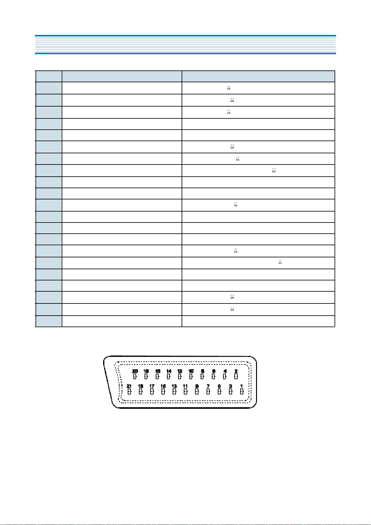
PIN Signal Designation Matching Value
Specifications
1 Audio Out (linked with 3)
2 Audio In (linked with 6)
3 Audio Out (linked with 1)
4 Audio Earth
5 Blue Earth
6 Audio in (linked with 2)
7 Blue in
8 Slow (Function) Switching
9 Green Earth
10 NC
11 Green In
12 NC
13 Red Earth
14 Rapid(Blanking) Switching Earth
15 Red In, C In
16 Rapid(Blanking) switching
0.5Vrms, Imp < 1 k • (RF 60% MOD)
0.5Vrms, Imp < 10 k
0.5Vrms, Imp < 1 k •(RF 60% MOD)
0.5Vrms, Imp < 10 k •(RF 60% MOD)
+
0.7Vpp 2dB, Imp 75
-
TV : 0-2V, PERI : 9.5 - 12V, Imp > 10 k
+
0.7Vpp 2dB, Imp 75
-
+
0.7Vpp 2dB, Imp 75
-
Logic 0 : 0 - 0.4V, Logic 1 : 1 - 3V, Imp 75
17 Video Earth
18 Rapid Blanking Earth
19 Video Out
20 Video In, Y In
21 Common Earth
+
1Vpp 2dB, Imp 75
-
+
1Vpp 2dB, Imp 75
-
4
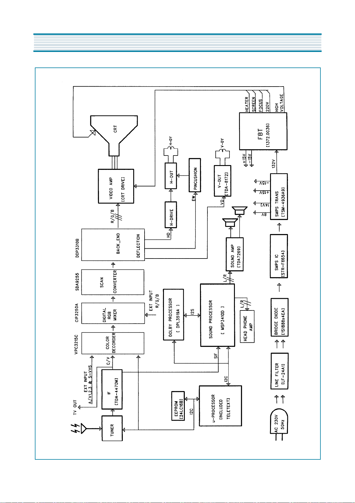
3. Circuit Block Diagram
5
4. Alignment Instructions
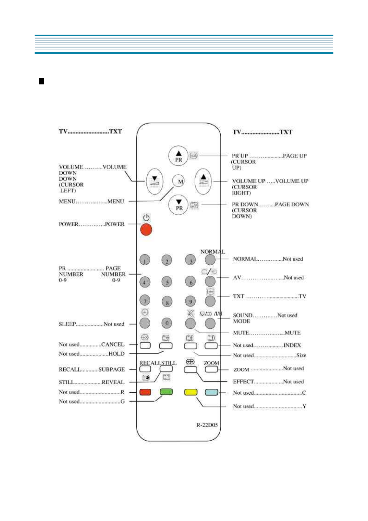
4-1. User Remocon
R-22D05
6
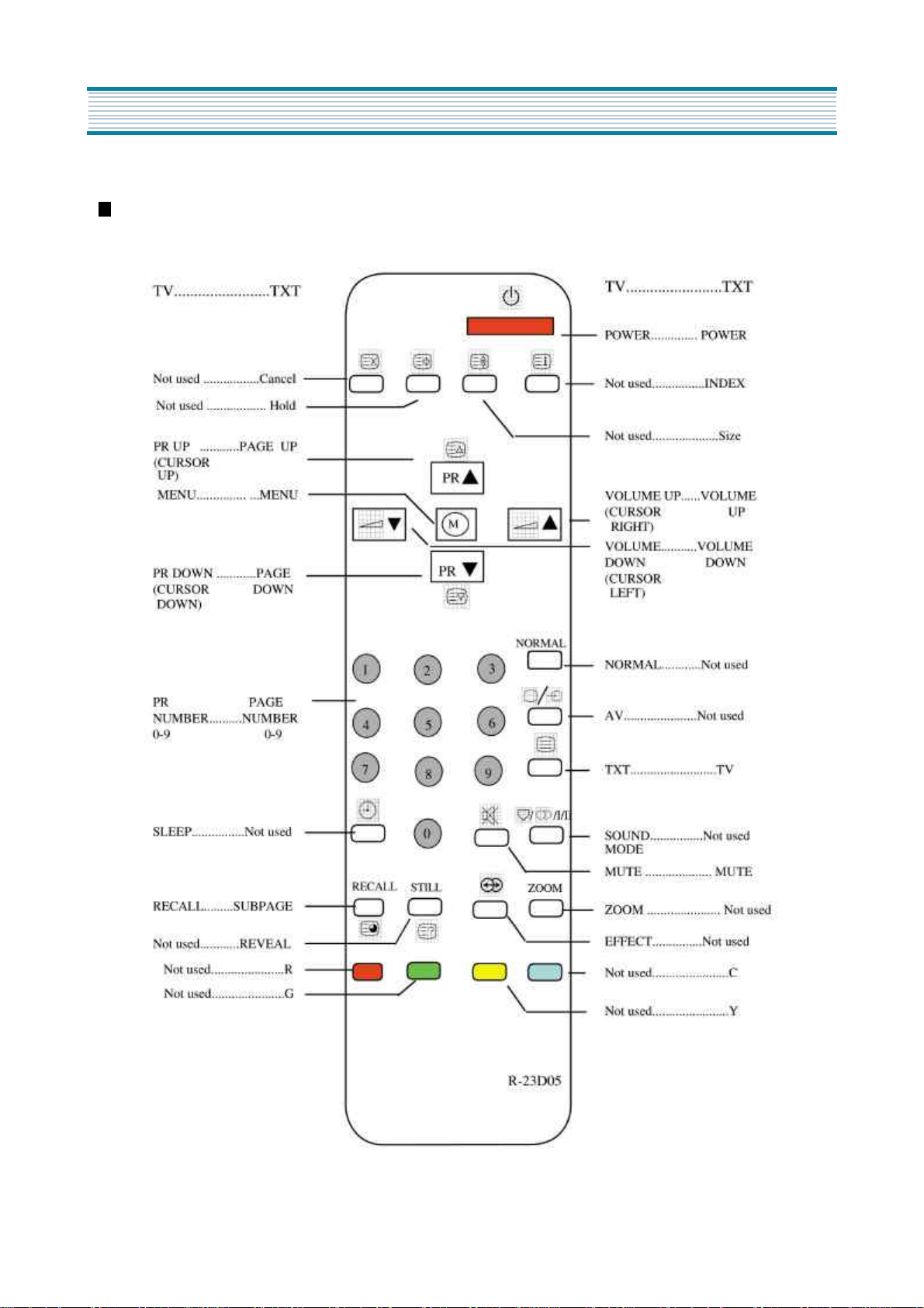
R-23D05
Alignment Instructions
7
Alignment Instructions
* How to Enter the "Service Mode" with user remocon.
1) Set the TV Pr 91
2) Sharpness " MIN " control.
3)Press the Red, Green, Menu buttons in regular sequency within 5 seconds after setting TV power off.
4) You can see the Menu of " Srvice Mode" on the screen.
5) The PR UP/DOWN buttons on the remote controller are used to move the selection bar up or down the Menus.
6) The VOL UP/DOWN buttons on the remote controller are used to adjust levels.
7) If you want to exit from " Service Mode" then power the TV off.
SVC v1
V. Slope
V. Center
V. Size
S. Curve
H. Center
H. Width
EW. Para
EW. Cor T
EW. CB
EW.Sym
R. bias
G. b
B. b
R. drive
G. d
B. d
G2
Sub Bri
DT
005
995
220
019
-190
510
382
028
500
021
370
311
311
330
315
330
330
021
048
- You can see the SVC Menu by OSD in TV set.
8

Alignment Instructions
4-2. AFT
Standard B/G, D/K, I and L
1) Set a Signal Generator with
- RF FREQUENCY = 38.9 MHz,
- RF OUTPUT LEVEL = 80 5dBuV
- Pattern = Color Bar
- System = PAL-B/G
2) Connect the Signal Generator RF Output to TP2 (Tuner IF Output).
There must be no signal input to the tuner.
3) Set the L109 to TP1(I101, #22) with DC Voltage to 2.5V 0.1V
+
-
+
-
4-3. AGC
1) Set a Pattern Generator with RF LEVEL 60 3dBuV, RF Frequency 210. 25MHz(10CH), Pattern Color Bar.
2) Connect a OSCILLOSCOPE PROBE to P101 (TUNER AGC INPUT).
3) Set the RBOI to P101(Tuner AGC Input) with DC Voltage to 2.8V 0.2V
+
-
+
-
4-4. SCREEN (G2)
1) Set a Pattern Generator with - RF Frequency : 210.25MHz (10CH)
- Pattern : RETMA
2) Select the “G2” in Menu
3) And a Horizontal Line will appear on the screen.
4) Adjust the SCREEN VOLUME on FBT barely to see the Horizontal Line.
5) Press the PR UP/DOWN keys to finish the SCREEN adjustment.
4-5. FOCUS
1) Apply a RETMA PATTERN signal.
2) Adjust the FOCUS VOLUME on FBT to obtain optimal resolution.
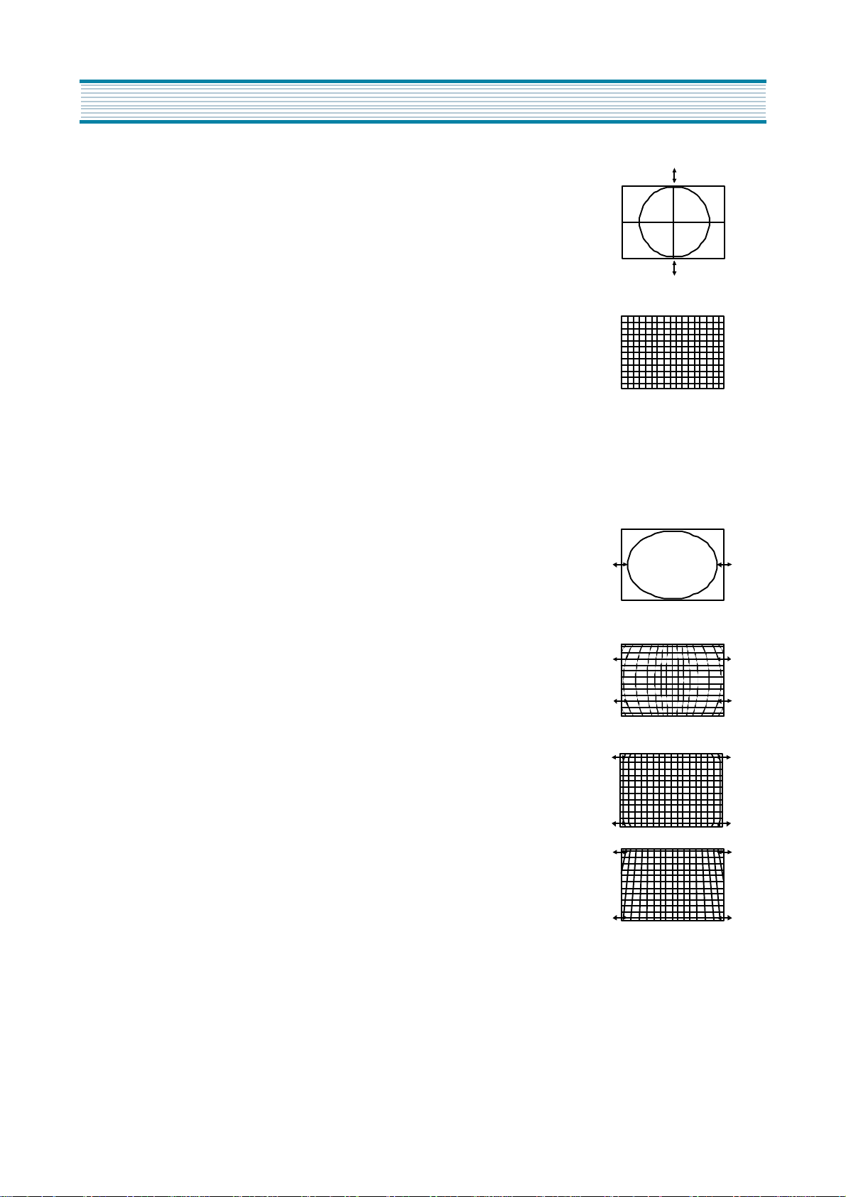
4-6. GEOMETRY
4-6-1 VERTICAL SLOPE ( Fixed : Adjust if need be )
1) Apply a RETMA PATTERN Signal.
2) Set the TV to Normal I mode.
3) Adjust the higher semicircle and the lower semicircle to be the same, with the V.Slope by volume
Up/Down keys.
4-6-2 VERTICAL CENTER
1) Apply a RETMA PATTERN Signal.
2) Set the TV to Normal I mode.
3) Adjust the center of the picture with the V.Center by volume Up/Down keys.
9
Alignment Instructions
4-6-3 VERTICAL SIZE
* The VERTICAL CENTER adjustment has to be done in advance.
1) Apply a RETMA PATTERN Signal.
2) Set the TV to Normal I mode.
3) Adjust the VERTICAL SIZE of the picture with the select V.size by
volume UP/DOWN keys.
4-6-4 VERTICAL S-CORRECTION ( Fixed : Adjust if need be )
1) Apply a CROSSHATCH PATTERN Signal.
2) Adjust the S-CORRECTION to obtain the same distance between
horizontal lines with the S.Curve by volume UP/DOWN keys.
4-6-5 HORIZONTAL CENTER
1) Apply a RETMA PATTERN Signal.
2) Adjust picture centering with the select H.Center by volume UP/DOWN keys.
4-7. EW
4-7-1 WIDTH
1) Apply a RETMA PATTERN Signal.
2) Adjust the horizontal width to make a perfect circle with the select H.Width
by volume UP/DOWN keys.
4-7-2 PARA
1) Apply a CROSSHATCH PATTERN Signal.
2) Adjust the vertical line to straight with the select E.W Para by volume
UP/DOWN keys.
4-7-3 CORNER ( Fixed : Adjust if need be )
1) Apply a CROSSHATCH PATTERN Signal.
2) Adjust the vertical line to straight with the select EW.Cor T by volume
UP/DOWN keys.
4-7-4 SYMMETRY ( Fixed : Adjust if need be )
1) Apply a CROSSHATCH PATTERN Signal.
2) Adjust the symmetrical balance to be suitable with the select EW Sym by
volume UP/DOWN keys.
10

4-8. WHITE BALANCE
4-8-1 RGB Reference R
Alignment Instructions
4-8-2 Beam Reference LOW ( 288, 301 : 10Cd/ )
HIGH ( 288, 301 : 10Cd/ )
m
2
2
m
4-8-3 Adjust G, B Gain with select Menu G,B of BIAS, DRIVE of select Menu so that R, G, B Bars
are on the center position of the analog meter. If R Analog meter is not on center, control
the Brightness +/- of user Remocon so as R Analog meter to be on the center position.
4-9. SUB BRIGHT
4-9-1 Pattern : Retma
4-9-2 Adjust the SUB BRIGHT with the select Sub Bri by volume UP/DOWN keys.
so that only H-Center parts of picture can be seen.
4-10. DOUBLE TEXT CENTER
4-10-1 Pattern : Pattern RED
4-10-2 Select Menu
4-10-3 Select DT in SVC menu time to see the Double Text Picture.
( Left : RF Picture, Right : Text Picture )
4-10-4 Change the Double Text control keys volume UP/DOWN keys so that the left edge of text
picture concur with the right edge of RF picture.
11

5. IC description
5-1. ST92195
(1) General Description
1.1 INTRODUCTION
The ST92195 microcnontoller is developed and manufactured by STMicroelecrtonics using a proprietary n-well
HCMOS process. Its performance derives from the use of
a flexible 256-register programming model for ultra-fast
context switching and real-time event response. The intelligent onchip peripherals offload the ST9 core from I/O
and data management processing tasks allowing critical
application tasks to get the maximum use off core
resources. The ST92195 MCU supports low power consumption and low voltage operation for power-efficient
and low-cost embedded systems.
1.1.1 ST9+Core
The advanced Core consists of the Central Processing
Unit (CPU), the Register File and the Interrupt controller.
The general-purpose registers can be used as accumulator, Index register, or address pointers. Adjacent register
pairs make up 16-bit registers for addressing or 16-bit
processing. Although the ST9 has an 8-bit ALU, the chip
handles 16-bit operations, including arithmetic, loads/
stores, and memory/register and memory/memory
exchanges. Two basic memory spaces are available :
Program Memory and the Register File, Which includes
the control and status registers of the on-chip peripherals.
1.1.2 Power Saving Modes
To optimize performance versus power consumption, a
range of operating modes can be dynamically selected.
Run Mode.
CPU and peripherals running at the maximum clock
speed delivered by the phase Locked Loop(PLL) of the
Clock Control Unit(CCU).
Wait For Interrupt Mode.
rupt(WFI) instruction suspends program execution until
an interrupt request is acknowledged. During WFI, the
CPU clock is halted while the peripheral and interrupt
controller keep running at a frequency programmable via
the CCU. In this mode, the power consumption of the
device can be reduced by more than 95%(LP WFI).
Wait For Interrupt Mode.
rupt(WFI) instruction, and if the Watchdog is not enable,
the CPU and its peripherals stop operation and the I/O
This is the full speed execution mode with
The Wait For Inter-
The Wait For Inter-
ports enter high impedance mode. A reset is necessary to
exit from Halt mode.
1.1.3 I/O Ports
Up to 28 I/O lines are dedicated to digital Input/Output.
These lines are grouped into up to five I/O Ports and can
be configureed on a bit basis under software control to provide timing, status signals, timer and output, analog inputs,
external interrupts and serial or parallel I/O.
1.1.4 TV Peripherals
A set of on-chip peripherals form a complete system for TV
set and VCR applications:
- Voltage Synthesis
- VPS/WSS Slicer
- Teletext Slicer
- Teletext Display RAM
- OSD
1.1.5 On Screen Display
The human interface is provided by the On Screen Display
module, this can produce up to 26 lines of up to 80 characters from a ROM defined 512 character set. The character
resolution is 10x10 dot. Four character sizes are supported. Serial attributes allow the user to select foreground
and background. Parallel attributes can be used to select
additional foreground and background colors and underline
on a character by character basis.
1.1.6 Teletext and Display RAM
The internal 8k Teletext and Display storage RAM can be
used to store Teletext pages as well as Display parameters.
1.1.7 Teletext, VPS and WSS Data Slicers
The three on-board data slicers using a single external
crystal are used to extract the Teletext, VPS and WSS
information from the video signal. Hardware Hamming
decoding is provided.
1.1.8 Voltage Synthesis Tuning Control
14-bit Voltage Synthesis using the PWM (Pulse Width
Modulation)/BRM (Bit Rate Modulation) technique can be
used to genetate tuning voltages for TV set applications.
The tuning voltage is output on one of two separate output
pins.
12

IC description
1.1.9 PWM Output
Control of TV settings is able to be made with up to eight
8-bit PWM outputs, with a frequency maximum of
lutions with higher frequency operation can be programmed.
1.1.10 Serial Peripheral Interface (SPI)
The SPI bus is used to communicate with external
devices via the SPI, or bus communication standards. The SPI uses one or two lines for serial data and a
synchronous clock signal.
2
I C
1.1.11 Standard Timer (STIM)
The Standard Timer includes a programmable 16-bit
down counter and an associated 8-bit prescaler with Single and Continuous counting modes.
1.1.12 Analog/Digital Converter (ADC)
In addition there is a 3 channel Analog to Digital Converter with integral sample and hold, fast 5.7us conver-
sion timer and 6-bit guaranteed resolution.
(2) Feature
Register File based 8/16 bit Core Architecture with
RUN, WFI, SLOW and HALT modes
to operating temperature range
0 CO70 C
Up to 24 MHz Operation @5V 10%
Minimum instruction cycle time : 375ns at 16MHz internal clock
64K Bytes ROM
256 Bytes RAM of Register file(accumulator or index
registers)
256 Bytes of on-chip static RAM
8K Bytes of TDSRAM(Teletext and Display RAM)
56-lead Shrink DIP package
28 fully programmable I/O pins
Serial Peripheral Interface
Flexible Clock controller for OSD, Data Slicer and Core
clocks running from one single low frequency external
crystal.
Enhanced Display Controller with 26 rows of 40/80
characters
- Serial and Parallel attributes
- 10x10 dot Matrix, 512 ROM characters, definable by
user
- 4/3 and 16/9 supported
O
+_
- Rounding, fringe, double width, double height,
scrolling, cursor, full background colour,
semitransparent mode and reduced intensity colour
supported
Teletext unit, including Data slicer, Acquisition Unit and
up to 8K Bytes RAM for Data Storage
VPS and Wode Screen Signalling slicer
Integrated Sync Extractor and Sync Controller
14-bit Voltage Synthesis for tuning reference voltage
Up to 6 external interrupts plus 1 non-maskable interrupt
8x8-bit programmable PWM outputs with 5V opendrain or push-pull capability
16-bit Watchdog timer with 8-bit prescale
16-bit standard timer with 8-bit prescaler usable as a
Watchdog timer
3-channel Analog-to-Digital converter ; 6-bit guaranteed
Rich instruction set and 14-Addressing modes
Versatile Development Tools, including Assembler,
Linker, C-compiler, Archiver, Source Level Debugger
and Hardware Emulators with Real-Time Operating
System available from third parties
Piggyback board available for prototyping
13
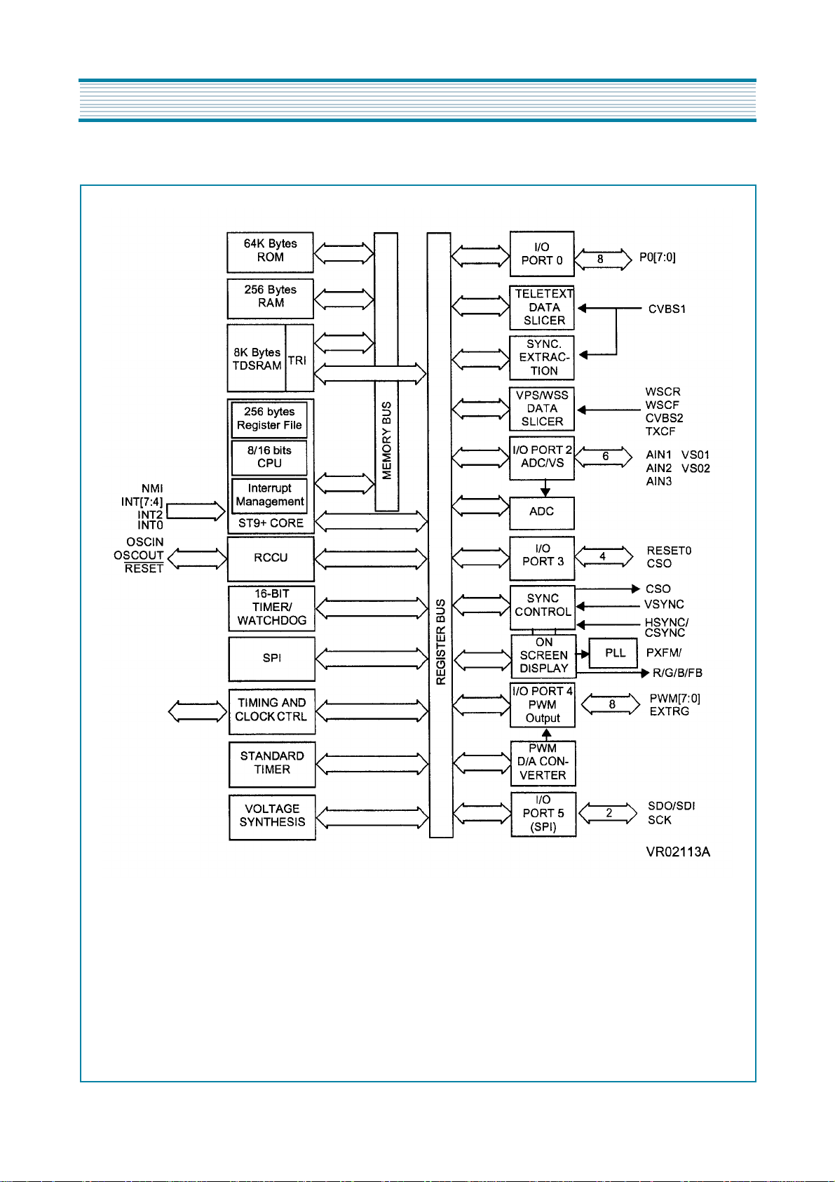
IC description
(3) Block Diagram
14
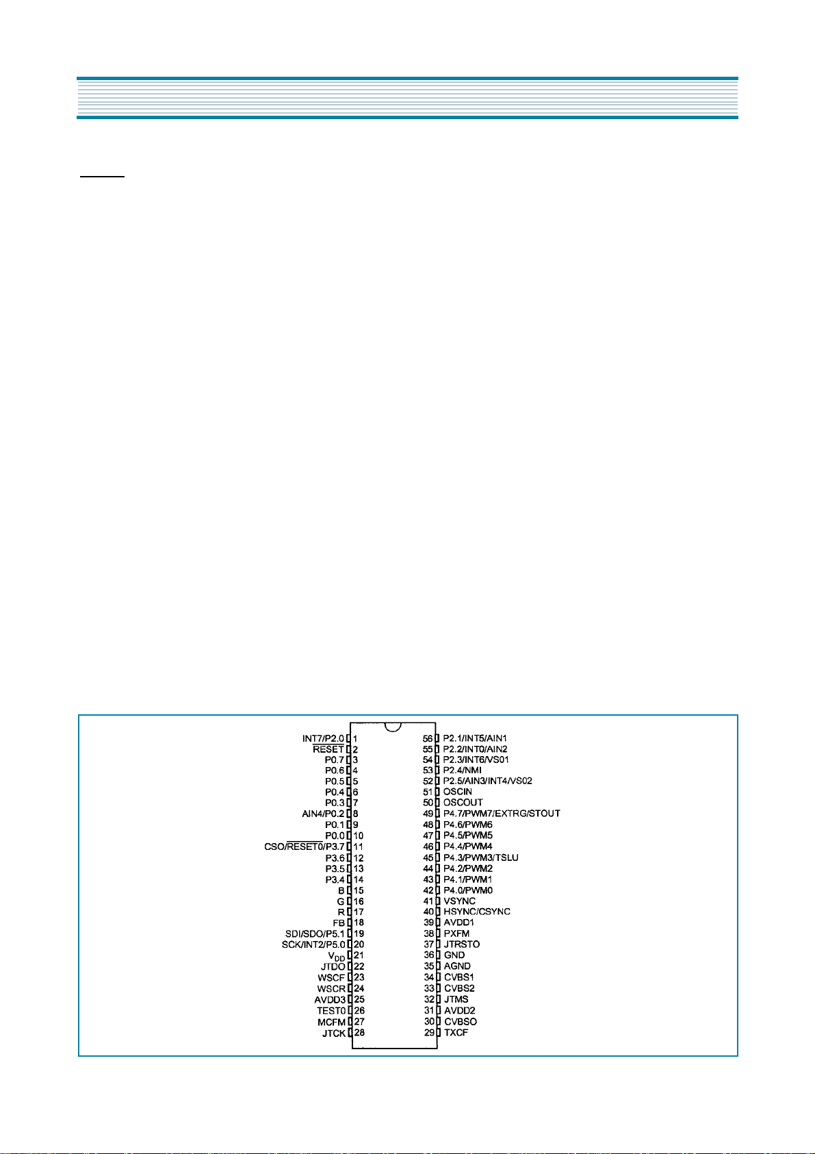
(4) PIN DESCRIPTION
IC description
RESET Reset(input, active low). The ST9+ is initialised
by the Reset signal. With the deactivation of RESET,
program execution begins from the Program memory
location pointed to by the vector contained in program
memory locations 00h and 01h.
R/G/B Red/Green/Blue.Video color analog DAC out-
puts
FB Fast Blanking. Video analog DAC output.
VOD Main power supply voltage(5V 10%, digital)
WSCF, WSCR Analog pins for the VPS/WPP slicer line
PLL.
MCFM Analog pin for the display pixel frequency multiplier.
OSCIN, OSCOUT Oscillator(input and output).
These pins connect a parallel-resonant crystal(24MHz
maximum), or an external source to the on-chip clock
oscillator and buffer. OSCIN is the input of the oscilltor
inverter and internal clock generator; OSCOUT is the
HYNC/CSYNC Horizontal/Composite sync. Horizontal
or composite video synchronisation input to OSD. Positive or negativety.
PXFM Analog pin for the Display Pixel Frequency Multiplier
AVDD Analog VDD of PLL. This pin must be tied to
VDD externally to the ST92195.
GND Digital circuit ground.
AGND Analog circuit ground(must be tied externally to
digital GND).
CVBS1 Composite video input signal for the Teletext
slicer and sync extraction.
CVBS2 Composite video input signal for the VPS/WSS
slicer. Pin AC coupled.
AVDD1, AVDD2 Analog power supplies(must be tied
externally to AVDD).
TXCF Analog pin for the VPS/WSS line PLL.
CVBSO, JTDO, JTCK Test pins : leave floating.
output of the oscillator inverter.
VSYNC Vertical Sync. Vertical video synchronisation
input to OSD. Positive or negative polarity.
Figure 2. Pin Description
JTMS, TEST0 Test pins : must be tied to AVDD2.
JTRST0 Test pin : must be tied to GND.
15
 Loading...