

Daewoo CP-325 Service Manual
1GOODMANS 1418 R
General Information
Also Covers
DTC-14B1 VUP
Daewoo CP-325
Matrix
Item
CRT Purity Adjustments - See Note
X-Ray Precautions
X-RAY RADIATION PRECAUTION
1 Excessive high voltage can produce poten-
tially hazardous X-RAY RADIATION. To avoid
such hazards, the high voltage must not
exceed the specified limit. The nominal value
of the high voltage of this receiver is 25.5kv
(14”: 23.5kv) at max beam current. The high
voltage must not, under any circumstances,
exceed 27.5kv (14”: 25.0kv). Each time a
receiver requires servicing, the high voltage
should be checked following the HIGH
VOLTAGE CHECK procedure. It is recommended the reading of the high voltage be
recorded as a part of the service records. It is
important to use an accurate and reliable high
voltage metre.
2. The only source of X-RAY RADIATION in this
TV receiver is the picture tube. For continued
X-RAY RADIATION protection, the replacement tube must be exactly the same type tube
as specified in the parts list.
Adjustments
SCREEN & WHITE BALANCE ADJUSTMENT
1.This adjustment is to be made only after
warming up at least 15 minutes.
2. Receive B,W pattern signal
3. Set the RGB Bias VR (RJ04, RJ13, RJ24) to
MINIMUM.
4. Set the G, B Drive VR (RJ1 4, RJ22) to
CENTER.
5. Set the CONTRAST, BRIGHTNESS,
COLOUR control to MIN, and Sub-brightness
control to CENTER.
6. Connect a short P501 to GND.
7. Rotate the SCREEN control to clockwise or
CCW so as to obtain dim horizontal line of
one color in R, G and B.
8. Rotate the R, G and B Bias VR of the other
color which did not appear on the screen
clockwise, until a dim white line is obtained.
9. Rotate the Screen control gradually anticlockwise until the last horizontal line
disappears on the screen.
10.Remove the short P501 and set the CONTRAST, BRIGHTNESS, COLOR control to
MAX.
11.Set the G, B Drive VR to obtain the best
white uniformity on the screen.
12.Rotate the CONTRAST, BRIGHTNESS,
COLOR controls until a dim raster is obtained
and touch-up adjustment of RGB Bias VR to
obtain the best white uniformity on the screen.
SUB-BRIGHTNESS ADJUSTMENT
1 White balance adjustment must proceed this
procedure.
2. Set the CONTRAST, BRIGHTNESS, COLOR
control to MIN.
3. Rotate the SUB-BRIGHTNESS VR (VR513)
gradually CCW until the last beam disappears
on the screen.
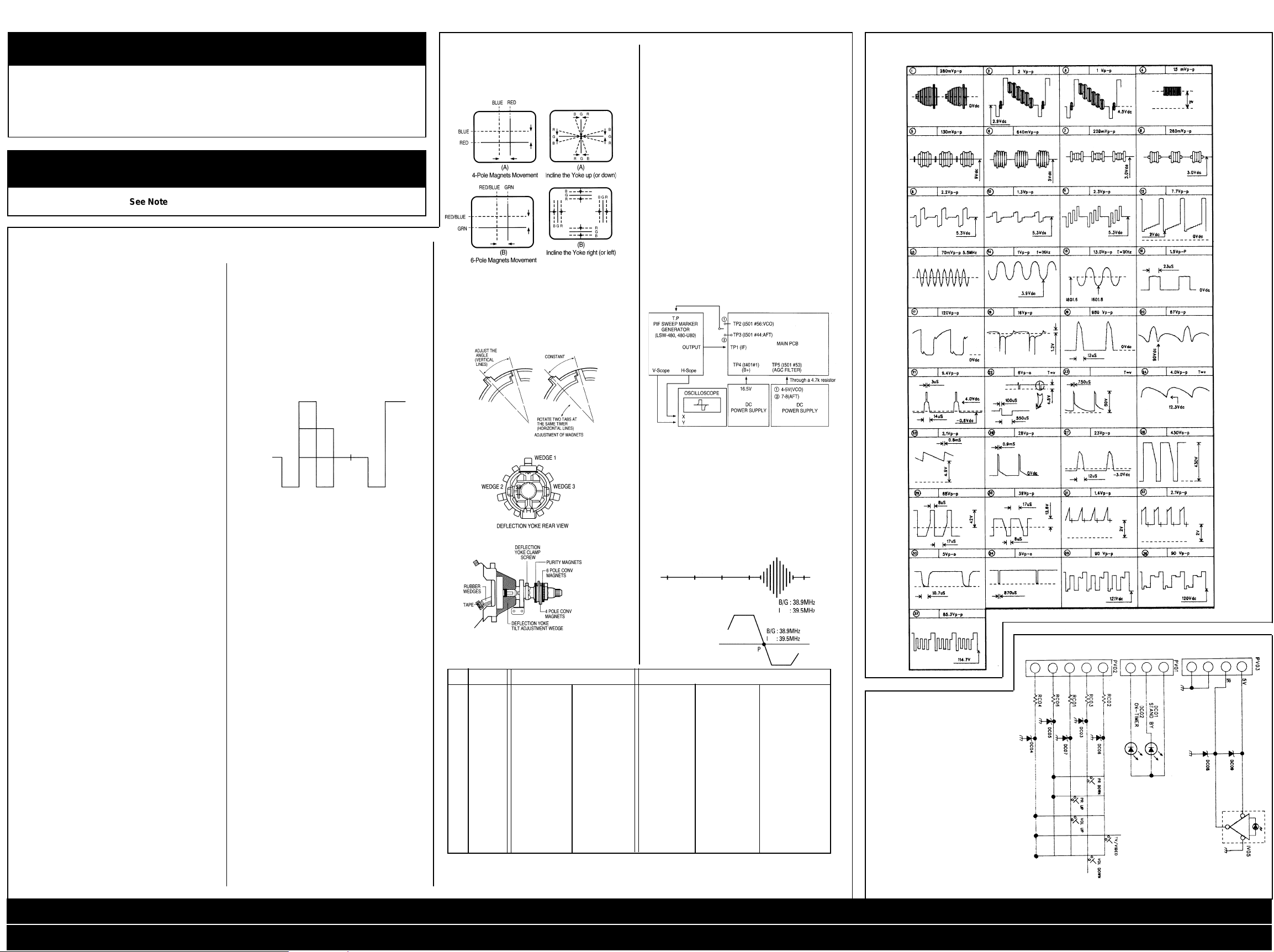
COLOUR AMPLITUDE AND PHASE
ADJUSTMENT
1. Receive a PAL/DEM Signal (Philips Model
PM5518)
2. Connect the probe of an oscilloscope to R203
(TP6:B-Y output)
3. Adjust L510 and VR516 in order to make the
waveform fine on the screen like Fig. 1.
Fig. 1
VERTICAL HEIGHT ADJUSTMENT
1. Receive RETMA pattern signal
2. Set the BRIGHTNESS control and CONTRAST control to Max., and the COLOR
control to centre.
3. Adjust VR306 for the optimum vertical height
and over scanning.
VERTICAL CENTRE ADJUSTMENT
1. Receive RETMA pattern signal.
2. Adjust VR317 so that the vertical center of the
picture may be coincident with the mechanical
center of CRT.
HORIZONTAL CENTRE ADJUSTMENT
1 Receive RETMA pattern signal.
2. Adjust VR426 so that the horizontal centre of
the picture may be coincident with the
mechanical centre of CRT.
FOCUS VOLTAGE ADJUSTMENT
1. Receive RETMA pattern signal.
2. Adjust the FOCUS VOLUME on the FBT and
make the picture on the screen be finest.
RF AGC ADJUSTMENT
1. Receive PAL COLOR BAR signal in the VHF
high band where the strength of signal can be
60-65 dB.
2. Set the CONTRAST control to Max., the
BRIGHTNESS control to provide adequate
black and grey scales.
3. Maintain the fine tuning on the screen, and
adjust VR130 (AGC DELAY CONTROL VR.)
in order that it may be located on the position
which the picture noise disappear on the
image.
MAIN B + (+103V) ADJUSTMENT
1. Receive RETMA pattern signal.
2. Set the picture level to NORMAL mode.
3. Connect DC voltage meter to the TP7 and
adjust VR801 for +103V DC.
Fig. 1 Fig. 2
Fig. 1
Centre Convergence by Convergence Magnets
Fig. 2
Circumference Convergence by DEF. Yoke
Fig. 3 Adjustment of magnets
Fig. 4 Rubber wedge location
Fig. 5 Picture tube neck component
Tube Size Table
NO. LOC. 14” 20”
1 CRT ORION POLKOLOR ORION SAMSUNG POLKOLOR
2 CRT ISM—01 CTV3240—0501 ISM—03 CTV3240—0501
SOCKET
3 D/COIL DC—1450 DC—2050
4 T401 DCF—2077D FSA24006S DCF-2217J FSA—17013M FSA26012M
5 L404 L—125 1—76 L—102 L—62 L—76
6 R413 1W 4.7ohm(F) 1W 0.33ohm(F) 1W 6.2ohm(F) 1W 2.7ohm(F) 1W 2ohm(F)
7 R416 1/4W 390K 1/4W 330K 1/4W 240K 1/4W 270K 1/4W 240K
8 R417 1/4W 390K 1/4w 330K 1/4W 240K 1/4W 270K 1/4W 240K
9 R530 1/6W 4.3K 1/5W 22K
10 R540 1/6W 1K 1/5W 56K
11 C406 1.6KV 6000P 1.6KV 6000P 1.6KV 6900P 1.6KV 8200P 1.6KV 7500P
12 C421 200V 0.47u 200W 0.51u 200V 0.47u 200V 0.51u 200V 0.51u
13 C414 — 2KV 470P — 2KV 660P 2KV 470P
A34JLL90X A34EFU13X A4JLL90X A4BECR11XI6 A4BEEV33X01
➔
1142.50258
➔
➔
VCO/AFT ADJUSTMENT
1. APPARATUS CONNECTION &
PRESETTING CONNECTION
1. Connect H-out of LSW-480 to X-axis of the
oscilloscope and V-out of LSW-480 to Y-axis
of the oscilloscope.
2. Connect the sweep signal output to TP1.
3. Set ATTENUATOR of LSW-480 to 30dB.
4. Supply 16.5V D.C. voltage (B+) to TP4.
5. Supply 4-5V D.C. voltage to TP5:VCO.
6. Supply 7-8V D.C. voltage to TP5:AFT.
PRESET
1) Oscilloscope Scaling
D.C level.
b) Set the horizontal time display to X-Y c) Put
the horizontal axis (X) to 1V/div. and the
vertical axis (Y) to 2V/div.
2) LSW-480 MARKER FREQ. SETTING.
fp(n+1) fs fc fp-2 fp fs(n-1)
B/G 31.9 33.4 34.5 36.9 38.9 40.4
P-I 31.9 33.5 35.07 37.5 39.5 41
Connection for PIF Adjustments
II. ADJUSTMENT OF VCO (B/G, I)
1. Connect the test point of LSW-480 to TP2.
2. Adjust L109 (ACO COIL) so that the P marker
point is located on the reference level.
Ill. ADJUSTMENT OF AFT B/G, I)
1. Connet the test point of LSW-480 to TP3
2. Adjust L108 (AFT COIL) so that the P marker
point is located on the reference level.
VCO Waveform
AFT Waveform
➔
➔
➔
Waveforms
➔
➔
Control
➔
➔
Diagram
X-Ray Precautions / Adjustments / Tube Size Table / Waveforms / Control Diagram / Troubleshooting / Troubleshooting Cont’d
CRT Diagram / Remote Control Diagram / Main Diagram / Main Diagram Cont’d
2GOODMANS 1418 R
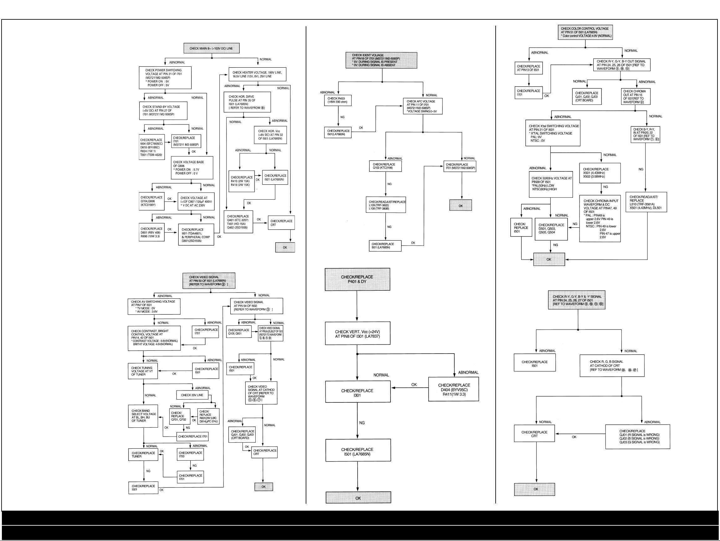
Troubleshooting
Guides
1. No Raster
3. Auto Search Trouble (Channel Skip)
5. No Colour
2. No Picture (Raster OK)
4. No Vertical Scanning
(One Horizontal Line On Screen)
6. No Specific Colour
X-Ray Precautions / Adjustments / Tube Size Table / Waveforms / Control Diagram / Troubleshooting / Troubleshooting Cont’d
CRT Diagram / Remote Control Diagram / Main Diagram / Main Diagram Cont’d
 Loading...