

Page 1
DAEWOO CP-310
1
General Information
Also Covers:
DVT-1484D, DVT-2084D
Ferguson
FG 14 CB 12V, FG 20 CB 12V
Goodmans
TVC 1400 & TVC 14 VP
Electrical Adjustments (TV)
GENERAL INFORMATION
All adjustments are throughly checked and
corrected when the receiver leaves the factory.
Therefore the receiver should operate normally
and produce proper colour and B/W pictures
upon installation. But, several minor adjustments may be required depending on the
particular location in which the receiver is
operated. This receiver is shipped completely in
a card-board carton. Carefully draw out the
receiver from the carton and remove all packing
materials.
Plug the power cord into a AC power outlet.
Turn the receiver ON and adjust the FINE
TUNING for the best picture detail. Check and
adjust all the customer controls such as
BRIGHTNESS, CONTRAST and COLOUR
Controls to obtain a natural B/W picture.
PROTECTION CIRCUIT CHECK
1. Turn on the receiver.
2. The receiver must be turned off and changed
in stand-by mode.
HIGH VOLTAGE CHECK
1. Connect an accurate high voltage metre to
the anode of the picture tube.
2. Turn on the receiver. Set the BRIGHTNESS
and CONTRAST controls to minimize (zero
beam current).
3. High voltage should be below 27.5kv
(14:25.0kv, 21”: 29.0kv)
AUTOMATIC DEGAUSSING
A degaussing coil is mounted around the picture
tube so that external degaussing after moving
the receiver is normally unnecessary. Providing
the receiver is properly degaussed upon
installation. The degaussing coil operates for
about 1 second after the power of the receiver is
switched ON. If the set is moved or placed in a
different direction, the power switch must be
switched off for at least 15 minutes in order to
make the automatic degaussing circuit operate
properly.
Should the chassis or parts of the cabinet
become magnetized to cause poor colour purity,
use an external degaussing coil. Slowly move
the degaussing coil around the faceplate of the
picture tube, the sides and front of the receiver
and slowly withdraw the coil to a distance of
about 2m before disconnecting it from the AC
source.
If colour shading still persists, perform the
COLOUR PURITY ADJUSTMENT and CONVERGENCE ADJUSTMENTS procedures, as
mentioned later.
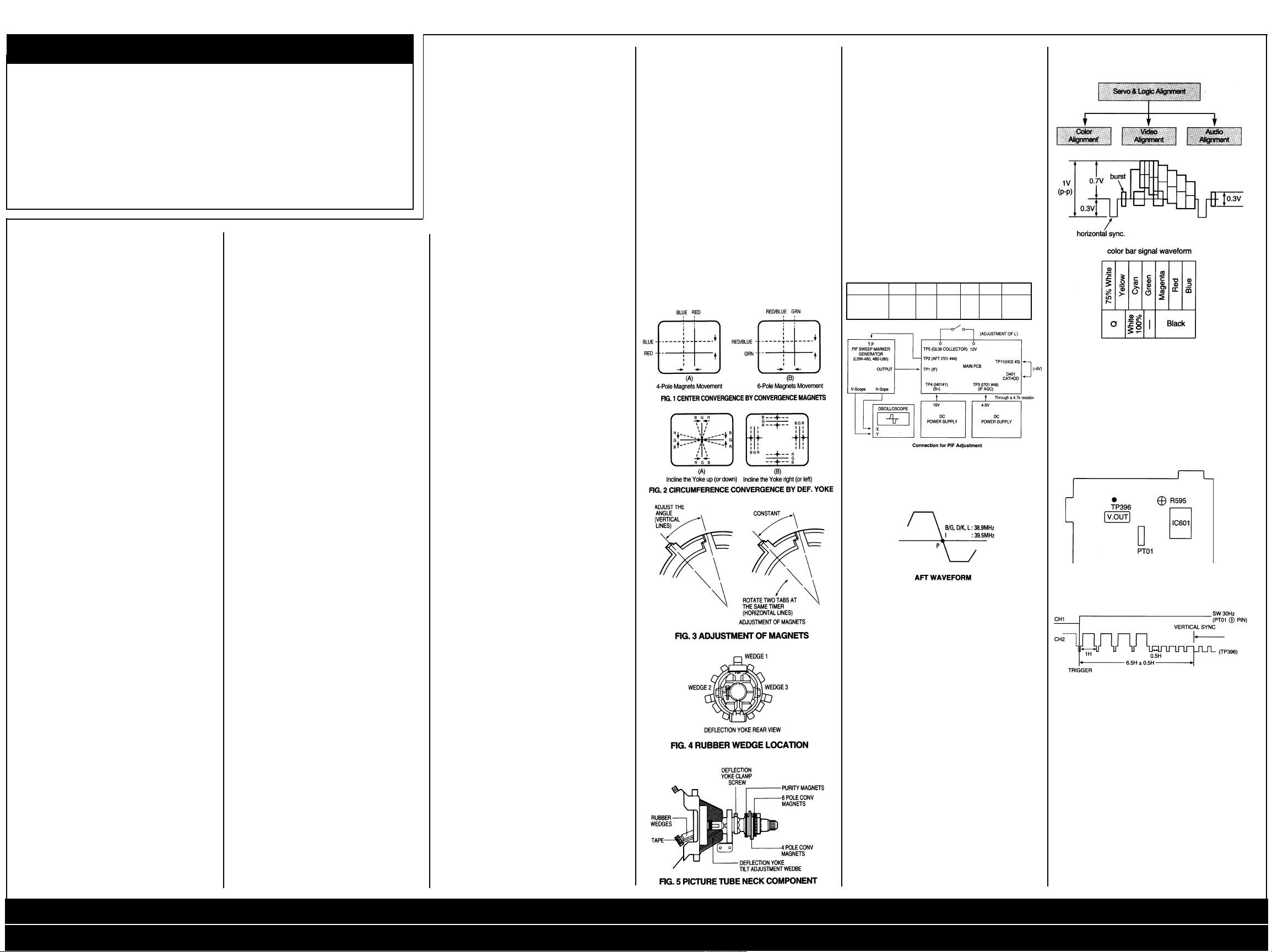
DYNAMIC CONVERGENCE ADJUSTMENT
Dynamic convergence (convergence of the
three colour field at the edges of the CRT
screen) is accomplished by proper insertion and
positioning of three rubber wedges between the
edges of the deflection yoke and the funnel of
the CRT. This is accomplished as follows:
1. Switch the receiver on allow it to warm up for
15 minutes.
2. Apply crosshatch pattern from dot/bar
generator to the receiver. Observe spacing
between lines around edges of the CRT
screen.
3. Tilt the deflection yoke up and down, and
insert tilt adjustment wedges 1 and 2 between
the deflection yoke and the CRT until the misconvergence illustrated in figure. 2 (A) has
been corrected.
4. Tilt the deflection yoke right and left, and
insert tilt adjustment wedge 3 between the
deflection yoke and the CRT until misconvergence illustrated in figure. 2 (B) has
been corrected.
5. Alternately change spacing between, and
depth of the insertion of, the three wedges
until proper dynamic convergence is obtained.
6. Use a strong adhesive tape to firmly secure
latch of the three rubber wedges to the funnel
of the CRT.
7. Check purity and readjust, if necessary.
STATIC (CENTRE) CONVERGENCE
ADJUSTMENT
1. Switch the receiver on and allow it to warm
up for 15 minutes.
2. Connect the output of a crosshatch generator
to the receiver and concentrating on the
centre of the CRT screen, proceed as follows:
a. Locate the pair of 4 pole magnet rings.
Rotate individual rings (Change spacing
between tabs) to converge the vertical red
and blue lines. Rotate the pair of rings
(maintaing spacing between tabs) to converge the horizontal red and blue lines. (Refer
to fig. 1 (A))
b. After completing red and blue centre conver-
gence, locate the pair of 6 pole magnet rings.
Rotage individual rings (change spacing
between tabs) to converge the vertical red
and blue (Magenta) and green lines. Rotate
the pair of rings (maintaining spacing
between tabs) to converge the horizontal red
and blue (Magenta) and green lines. (Refer to
Fig. 1(B))
COLOR PURITY ADJUSTMENT
For the best result, it is recommended that the
purity adjustment is made in final receiver
location. If the receiver will be moved, perform
adjustment with it’s facing east. The receiver
must have been operating 15 minutes prior to
this procedure and the faceplate of the CRT
must be at room temperature. The receiver is
equipped with an automatic degaussing circuit.
But, if the CRT shadow mask has come
excessively magnetized, it may be necessary to
degauss it with manual coil. Do not switch the
coil.
The following procedure is recommended while
using a dot generation.
1. Check for correct location of all neck components (See figure. 5).
2. Rough-in the static convergence at the centre
of the CRT, as explained in the static convergence procedure.
3. Rotate the picture control to centre of its
rotation range, and rotate brightness control
to max. CW position.
4. Apply green color signal to procedure a green
raster.
5. Loosen the deflection yoke tilt adjustment
wedges (3), loosen the deflection yoke clamp
screw and push the deflection yoke as close
as possible to the CRT screen.
6. Begin the following adjustment with the tabs
on the round purity magnet rings set together,
initially move the tabs on the round purity
magnet rings to the side of the CRT neck.
Then, slowly separate the two tabs while at
the same time rotating them to adjust for a
uniform green vertical band at the CRT
screen.
7. Carefully side the deflection yoke backward to
achieve green purity. (uniform green screen)
Centre purity was obtained by adjusting the
tabs on the round purity magnet rings, outer
edge purity was obtained by sliding the
deflection yoke forward. Tighten the deflection
yoke clamp screw.
8. Check for red and blue field purity by applying
red signal and touch up adjustments, if
required.
9. Perform black and white tracking procedure.
SCREEN & WHITE BALANCE ADJUSTMENT
1. This adjustment is to be made only after
warming up at least 15 minutes.
2. Receive B/W pattern signal
3. Set the RGB Bias VR (R522, R512, R502) to
center.
4. Set the G, B Drive VR (R515, R505) to
CENTER.
5. Set the CONTRAST, BRIGHTNESS, COLOR
control to MIN, and Sub-brightness control to
CENTER.
6. Rotate the R, G and B Bias VR of the other
color which did not appear on the screen
clockwise, until a dim white is obtained.
7. Rotate the Screen control gradually anticlockwise until the last horizontal line
disappears on the screen.
8. Set the CONTRAST, BRIGHTNESS, COLOR
control to MAX.
9. Set the G, B Drive VR to obtain the best white
uniformity on the screen.
10.Rotate the CONTRAST, BRIGHTNESS,
COLOR controls until a dim raster is obtained
and touch-up adjustment of RGB Bias VR to
obtain the best white uniformity on the screen.
SUB-BRIGHTNESS ADJUSTMENT
1. White balance adjustment must proceed this
procedure.
2. Set the CONTRAST, BRIGHTNESS, COLOR
control to MIN.
3. Rotate the SUB-BRIGHTNESS VR (VRAO1)
gradually CCW until the last beam disappears
on the screen.
VERTICAL HEIGHT ADJUSTMENT
1. Receive RETMA pattern signal.
2. Set the BRIGHTNESS control and CONTRAST control to Max., and the COLOR
control to centre.
3. Adjust VR301 for the optimum vertical height
and over scanning.
VERTICAL CENTER ADJUSTMENT
1. Receive RETMA pattern signal.
2. Adjust VR302 so that the vertical center of the
picture may be coincident with the mechanical
center of CRT.
HORIZONTAL CENTER ADJUSTMENT
1. Receive RETMA pattern signal.
2. Adjust VR401 so that the horizontal centre of
the picture may be coincident with the
mechanical centre of CRT.
FOCUS VOLTAGE ADJUSTMENT
1. Receive RETMA pattern signal.
2. Adjust the FOCUS VOLUME on the FBT and
make the picture on the screen be finest.
RF AGC ADJUSTMENT
1. Receive PAL COLOR BAR signal in the VHF
high band where the strength of signal can be
60-65 dB.
2. Set the CONTRAST control to Max., the
BRIGHTNESS control to provide adequate
black and grey scales.
3. Maintain the fine tuning on the screen, and
adjust VR601 (AGC DELAY CONTROL VR.)
in order that it may be located on the position
which the picture noise disappear on the
image.
MAIN B+ (+103V) ADJUSTMENT
1. Set the Bright, Contrast and colour to MAX.
2. Connect DC voltage meter to the P405 and
adjust VR801 for +103V DC.
PIF ADJUSTMENT
1. APPARATUS CONNECTION &
PRESETTING
CONNECTION
1. Connect H-out of LSW-480 to X-axis of the
oscilloscope and V-out of LSW-480 to Y-axis
of the oscilloscope.
2. Connect the sweep signal output to TP1.
3. Set ATTENUATOR of LSW-480 to 30dB.
4. Supply 12V D.C. voltage (B+) to TP4.
5. Supply 4-5V D.C. voltage to TP3.
PRESET
1) Oscilloscope Scaling
a) Put the scale of X and Y of the oscilloscope
to D.C level.
b) Set the horizontal time display to X-Y
c) Put the horizontal axis (X) to 1V/div. and the
vertical axis (Y) to 2V/div.
2) LSW-480 MARKER FREQ. SETTING.
fp(n+1) fs fc fp-2 fp fs(n-1)
B/G, D/K, L 31.9 33.4 34.5 36.9 38.9 40.4
31.9 33.5 35.07 37.5 39.5 41
II. ADJUSTMENT OF AFT(B/G, D/K, I, L)
1. Connect the test point of LSW-480 to TP2.
2. Adjust L103 (AFT COIL) so that the P marker
point is located on the reference level.
Electrical Adjustments (VCR)
ALIGNMENT AND ELECTRICAL ADJUSTMENT
For these adjustment, use the equipment
mentioned below The suitable output waveform
of the color-bar singal and proceed by using the
alignment tape and video signal. generator is
shown below.
Instrument and Tools Required
1. Color TV receiver.
2. Oscilloscope having 10 MHz or more
bandwidth.
3. Color-bar generator.
4. Frequency counter.
5. VTVM.
6. VOM (20 kµ/V).
7. Audio oscillator.
8. Audio attenuator.
Signal Level and Input and Output Impedance
Requirement
1. Video input: Negative sync, 1 Vp-p standard
composite video signal, 75Ω.
2. Video output: Same as above.
3. Audio input: Line -5dBm 47KΩ.
4. Audio output: -5dBm, 10KΩ. or less.
Adjustment Sequence
The VCR should be adjusted in the sequence
shown below.
SERVO
1. PLAYBACK PHASE
Mode Play
Adjustment Parts R595
Check Point TP396
Test Equipments Oscilloscope
Test T ape DP-1
Location of Adjustments Parts
MAIN PCB
Observation Waveform
Horizontal Axis: S/DIV
Vertical Axis: CH1: SW30, CH2: V.OUT
Adjustment Procedure
1. Preparation
1) Play back on test tape (COLOR BAR).
2) Set the oscilloscope to the CHOP mode.
Connect CH1 to the SW PULSE (PT01 (3))
and CH2 to the VIDEO OUT (TP396) and
trigger the scope with the signal from CHi.
2. Adjustment
1) Adjust R595 to position the rising edge of SW
PULSE at 6.5H±0.5H from the V-SYNC.
VIDEO
1. EE LEVEL ADJUSTMENT
Mode EE (Stop)
Adjustment Parts R395
Check Point TP395
Test Equipments Oscilloscope Signal gen.
Input Signal Color bar signal with
100% white
Electrical Adjustments (TV) (VCR) / Electrical Adjustments (VCR) Cont’d / Head Amp Diagram / Audio Diagram / Remote Control / Video Diagram
Connection Diagrams (DVT-1484) (DVT-2084) / Main Diagram (TV) / Power Servo Syscon Diagrams (DVT 1484P) (DVT 2084P)
Page 2

2DAEWOO CP-310
Electrical Adjustments
(VCR) Cont’d
Location of Adjustments Parts
Main PCB
Observation Waveform
Horizontal Axis: 10µS/DIV
Vertical Axis: 0.1 V/DIV
Adjustment Procedure
1. Preparation
1) Set the LINE mode.
2) Supply the COLOR BAR signal with 100%
white to the VIDEO IN JACK.
2. Adjustment
1) Set the VCR to STOP (FE) mode.
2) Connect the oscilloscope to TP395 and
trigger the scope externally with the composite synchronous signal from TP31 3.
3) Adjust R395 to obtain 0.5±0.01 Vp-p between
the SYNC TIP and 100% white level.
2. PLAYBACK OUTPUT LEVEL
Mode PLAY
Adjustment Parts R396
Check Point TP396
Test Equipments Oscilloscope
Test T ape DP-1
Location of Adjustments Parts
Main PCB
Adjustment Procedure
1. Preparation
1) Set the SYSTEM SELECT SWITCH to the
AUTO MODE.
2) Play back the test tape (COLOR BAR).
2. Adjustment
1) Connect the oscilliscope to TP396 and trigger
the scope externally with the C.SYNC signal
from TP313.
2) Adjust R396 to obtain 2.0±0.1 Vp-p between
the SYNC TIP and 100% white level.
3. SYNC TIP FREQUENCY
Mode (STOP)
Adjustment Parts R391, R393
Check Point TP391
Test Equipments Frequency counter
Input Signal No signal
Location of Adjustments Parts
Main PCB
Adjustment Procedure
1. Preparation
1) Set the LINE mode.
2) Supply the input signal in the OPEN state.
2. Adjustment
1) Set the VCR to the FE (STOP) mode.
2) Connect the frequency counter to TP391.
3) Set the SYSTEM SELECT SWITCH to the
PAL mode.
4) Adjust R393 to obtain 3.8 ±0.1 Mhz.
4. FM DEVIATION
Mode REC PLAY
Adjustment Parts R392
Check Point TP396
Test Equipments Oscilloscope
Input Signal Color bar with
100% white
Location of Adjustments Parts
Main PCB
Adjustment Procedure
1. Preparation
1) Set the LINE mode.
2) Supply the COLOR BAR signal to the VIDEO
IN JACK.
2) Connect the oscilloscope to TP396 (VOUT)
and trigger the scope externally with the
C.SYNC signal from TP31 3.
3) Record the signal for about 10 seconds in SP
mode and play back the signal just recorded.
Confirm the playback output level is
2.0±0.2Vp-p.
2. Adjustment
If the playback output level is not 2.0±0.2Vp-p,
adjust as follows.
1) Adjust R392 a little.
2) Record the Color bar signal for about 10
seconds and play back the signal just
recorded.
3) Confirm the playback output level.
4) Repeat the procedure 1) to 4) until the
playback output level becomes 2.0±0.2Vp-p
between the SYNC TIP and 100% white peak.
5. C RECORD CURRENT
Mode EE
Adjustment Parts R399 & R491
Check Point TP399
Test Equipments Oscilloscope
Test Tape Blank T ape
Input Signal Color Bar
Location of Adjustments Parts
Main PCB
Observation Waveform
Horizontal Axis: 10µS/DIV
Vertical Axis: 20 mV/DIV
Test T ape Blank Tape
Input Signal Color Bar
Location of Adjustments Parts
Main PCB
Observation Waveform
Horizontal Axis: 10µS/DIV
Vertical Axis:50 mV/DIV
Adjustment Procedure
1. Preparation
1) Set the LINE mode.
2) Supply the COLOR BAR signal to the VIDEO
IN JACK.
2. Adjustment
1) Set the VCR to the EE mode.
2) Trigger the scope externally with the C.SYNC
signal from TP31 3.
3) Connect the oscilloscope to TP399.
Adjust R399 until Y-FM record current
becomes 300±10 mVp-p.
AUDIO
1. AUDIO PLAYBACK OUTPUT LEVEL
Mode Play
Adjustment Parts R291
Check Point Audio Output
Test Equipments Audio Level Meter
Test T ape DP-1
Location of Adjustments Parts
Main PCB
Location of Adjustments Parts
Main PCB
Adjustment Procedure
1. Preparation
1) Set the LINE mode.
2) Supply the signal in OPEN mode.
3) Connect the AUDIO level meter to both
TP201 and TP202.
4) After inserting a blank tape, record in SP
mode.
2. Adjustment
1) Adjust R292 to obtain 2.4mVrms.
3. Adjustment Inspection Standard
In comfirmation of recording playback
frequency characteristics, compared with 1
KHz recording-playback output level, (8KHz)
recording-playback output level is higher than
the standard, increase the record bias and if
lower, decrease it.
End
Observation Waveform
Horizontal Axis: S/DIV
Vertical Axis: 0.5 V/DIV
Electrical Adjustments (TV) (VCR) / Electrical Adjustments (VCR) Cont’d / Head Amp Diagram / Audio Diagram / Remote Control / Video Diagram
Observation Waveform
Horizontal Axis: 10µS/DIV
Vertical Axis: 0.5V/DIV
Adjustment Procedure
1. Preparation
1) Set the LINE mode.
2) Supply the COLOR BAR signal to the VIDEO
IN JACK.
2. Adjustment
1) Set the VCR to FE mode.
2) Connect the oscilloscope to TP399.
Adjust R399 until Y-FM record current
becomes minimum.
3) Trigger the scope externally with the C.SYNC
signal from TP313.
4) Adjust R491 until Color record current
becomes 80±5 mVp-p.
6. Y RECORD CURRENT
Mode FE
Adjustment Parts R399
Check Point TP399
Test Equipments Oscilloscope
Adjustment Procedure
1. Preparation
1) Connect the AUDIO level meter to the AUDIO
OUTPUT JACK.
2) Play back the test tape (DP-1).
2. Adjustment
1) Adjust R291 until the output level becomes
-5 ±1.5dBm.
2. AUDIO RECORD BIAS
Mode REC
Adjustment Parts R292
Check Point TP201, TP202
Test Equipments Audio Level Meter
Test T ape Blank Tape
Connection Diagrams (DVT-1484) (DVT-2084) / Main Diagram (TV) / Power Servo Syscon Diagrams (DVT 1484P) (DVT 2084P)
Page 3
DAEWOO CP-310
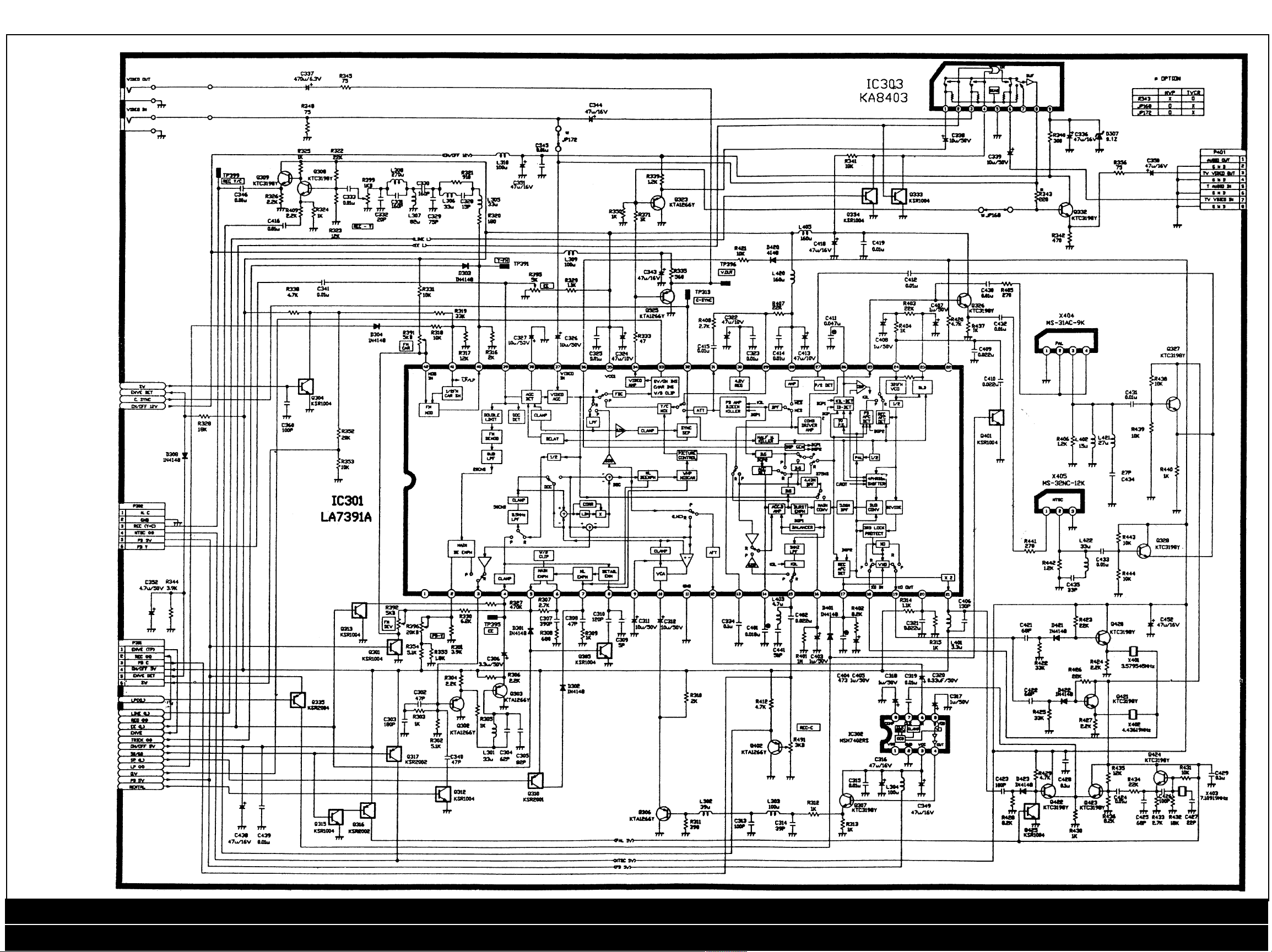
Video
Diagram
3
Electrical Adjustments (TV) (VCR) / Electrical Adjustments (VCR) Cont’d / Head Amp Diagram / Audio Diagram / Remote Control / Video Diagram
Connection Diagrams (DVT-1484) (DVT-2084) / Main Diagram (TV) / Power Servo Syscon Diagrams (DVT 1484P) (DVT 2084P)
Page 4

Audio Diagram
4DAEWOO CP-310
Remote
Control
Diagram
Head Amp
Diagram
Electrical Adjustments (TV) (VCR) / Electrical Adjustments (VCR) Cont’d / Head Amp Diagram / Audio Diagram / Remote Control / Video Diagram
Connection Diagrams (DVT-1484) (DVT-2084) / Main Diagram (TV) / Power Servo Syscon Diagrams (DVT 1484P) (DVT 2084P)
Page 5

DAEWOO CP-310
5
Connection Diagram
(DVT-1484)
Electrical Adjustments (TV) (VCR) / Electrical Adjustments (VCR) Cont’d / Head Amp Diagram / Audio Diagram / Remote Control / Video Diagram
Connection Diagrams (DVT-1484) (DVT-2084) / Main Diagram (TV) / Power Servo Syscon Diagrams (DVT 1484P) (DVT 2084P)
Page 6

6DAEWOO CP-310
Connection Diagram
(DVT-2084)
Electrical Adjustments (TV) (VCR) / Electrical Adjustments (VCR) Cont’d / Head Amp Diagram / Audio Diagram / Remote Control / Video Diagram
Connection Diagrams (DVT-1484) (DVT-2084) / Main Diagram (TV) / Power Servo Syscon Diagrams (DVT 1484P) (DVT 2084P)
Page 7

DAEWOO CP-310
Main
Diagram
(TV)
7
Electrical Adjustments (TV) (VCR) / Electrical Adjustments (VCR) Cont’d / Head Amp Diagram / Audio Diagram / Remote Control / Video Diagram
Connection Diagrams (DVT-1484) (DVT-2084) / Main Diagram (TV) / Power Servo Syscon Diagrams (DVT 1484P) (DVT 2084P)
Page 8

8DAEWOO CP-310
Power Servo Syscon Diagram (DVT 1484P)
Electrical Adjustments (TV) (VCR) / Electrical Adjustments (VCR) Cont’d / Head Amp Diagram / Audio Diagram / Remote Control / Video Diagram
Connection Diagrams (DVT-1484) (DVT-2084) / Main Diagram (TV) / Power Servo Syscon Diagrams (DVT 1484P) (DVT 2084P)
Page 9

DAEWOO CP-310
9
Power Servo Syscon Diagram (DVT 2084P)
Electrical Adjustments (TV) (VCR) / Electrical Adjustments (VCR) Cont’d / Head Amp Diagram / Audio Diagram / Remote Control / Video Diagram
Connection Diagrams (DVT-1484) (DVT-2084) / Main Diagram (TV) / Power Servo Syscon Diagrams (DVT 1484P) (DVT 2084P)
 Loading...