

Page 1
Document # PG10-007
44” (112.0 cm)
RDW24I, RDW24S
Revised 03/12/12 Page 1/3
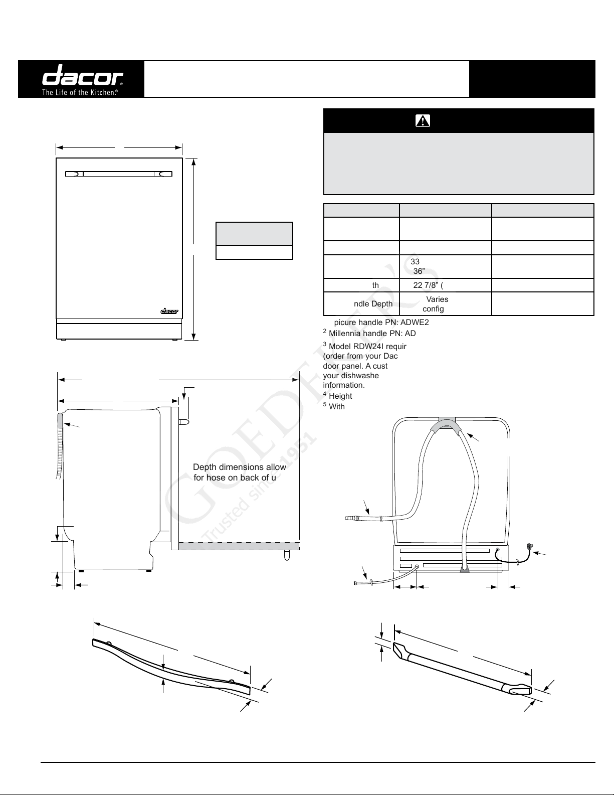
Product Dimensions
A
Front
Depth with door open
49 3/4” (126.4 cm)
Depth with door closed
C
Renaissance® 24” Wide
Built-In Dishwasher
Product tolerances: ±1/16” (±1.6 mm)
otherwise stated
Approximate
Shipping Weight
B
117 lbs. (53 kg.)
D Handle depth
PLANNING
GUIDE
WARNING
• Observe all governing codes and ordinances during planning
and installation. Contact your local building department for
further information.
• This appliance must be installed in accordance with the
accompanying installation instructions.
Model RDW24I Model RDW24S
Front Panel Type
(A) Width 23 1/2” (59.7 cm) 24” (61.0 cm)
(B) Height
(C) Depth 22 7/8” (58.1 cm)
(D) Handle Depth
1
Epicure handle PN: ADWE24HCH (chrome) or ADWE24HB (glossy black)
2
Millennia handle PN: ADWM24H (polished) or ARDWMH24 (brushed)
3
Model RDW24I requires installation of either a Dacor glass panel kit
(order from your Dacor dealer), or a customer provided, custom overlay
door panel. A custom overlay panel allows you to blend the exterior of
your dishwasher into the overall kitchen décor. See page 2/3 for more
information.
4
Height with required trim kit installed.
5
Without custom front panel installed.
Integrated
front panel
33 7/8” (86.0 cm) to
36” 1/2 (92.7 cm)
Varies with
conguration
2
Stainless steel
4
5
34 3/8” (87.4 cm) to
36 1/2” (92.7 cm)
22 7/8” (58.1 cm)
Epicure
Millennia®: 2” (5.1 cm)
®
: 2 1/2” (6.4 cm)
1
2
Drain hose
Side
6 1/4” (15.9 cm) to
8 1/4” (21.0 cm)
1 15/16” (4.9 cm)
Do not modify
loop in hose
Depth dimensions allow
for hose on back of unit
B
C
A
Drain hose
54” (137.0 cm)
long
Water supply line
60” (152.0 cm)
long
UTILITY CONNECTION DIMENSIONS
A
Back
3 3/8” (8.6 cm)
B
Power cord
long
2 7/8” (7.3 cm)
C
A = 1 3/8" (3.5 cm) B = 23" (58.40 cm) C = 2" (5.1 cm)
MILLENNIA STYLE HANDLE DIMENSIONS
(PART NUMBERS ADWM24H AND ARDWMH24)
All specications subject to change without notice.
A = 7/8" (2.2 cm) B = 18 1/2" (47.0 cm) C = 2 3/8" (6.0 cm)
EPICURE STYLE HANDLE DIMENSIONS
(PART NUMBERS ADWE24HCH AND ADWE24HCH)
Phone: (800) 793-0093www.dacor.com
Page 2
Document # PG10-007
RDW24I, RDW24S
Revised 03/12/12 Page 2/3
Renaissance 24” Wide
Built-In Dishwasher
Electrical Specifications
Dedicated Circuit Required
Grounded, 3-prong, electrical outlet
supplied by 120 Vac,
60 Hz, 15 Amp. (circuit breaker)
■ The above specifications are for reference only. For exact
specifications see the product data label, located inside the right door
■ Do not modify the power cord or use an extension cord. The power
cord may be disconnected from the appliance and hard-wired to a
junction box connected to a circuit meeting the above specifications if
the power cord is not long enough.
11 Amp. @ 120 Vac, 60 Hz.
Water Supply Specifications
■ Water Pressure: The water supply pressure must be between 4.2
and 140 psi (30-1000 kPa). The water supply line and the shut-off
valve must supply a flow volume of at least 3 gallons (12 liters) per
minute.
■ Water Supply Temperature: The dishwasher can be connected to a
cold or hot water supply (maximum 160°F, 70°C). Dacor recommends
using a hot water supply of 120°F (49°C) to 140°F (60°C). If a cold
water supply is used, the washing times will be longer, but the
performance will not be affected.
■ Water Supply Valve Requirement: 3/8” water supply valve for
connection to dishwasher’s water supply line is required in a location
where it is easily accessible after the dishwasher is installed. The
dishwasher water supply line is equipped with a 3/8” (1.0 cm) NPT
female compression fitting on the end.
Total
Connected Load
PLANNING
GUIDE
■ Floor must be solid and level. All cutout surfaces must be at right
angles. Surrounding cabinet must have sufficient material for
attachment of the anti-tip brackets (see installation instructions).
■ The electrical wiring, water supply and drain lines must enter through
the area indicated by the shading on the illustration below. Preferably,
they should come through the right side of the cabinet.
■ The access hole(s) in the cabinet for the power cord and water line
shallbenobiggerthan1-1/2˝(3.8cm)indiameter.Theaccesshole
forthedrainhoseshallbenobiggerthan2˝(5.0cm)indiameter.The
access holes for all three must be round and smooth. If the partition
is metal, it needs to be covered with an edge protector. Call Dacor for
the part number of an approved edge protector.
Cutout tolerances: +1/16” (+1.6 mm), -0
2” (5.1 cm)
4” (10.2 cm)
F
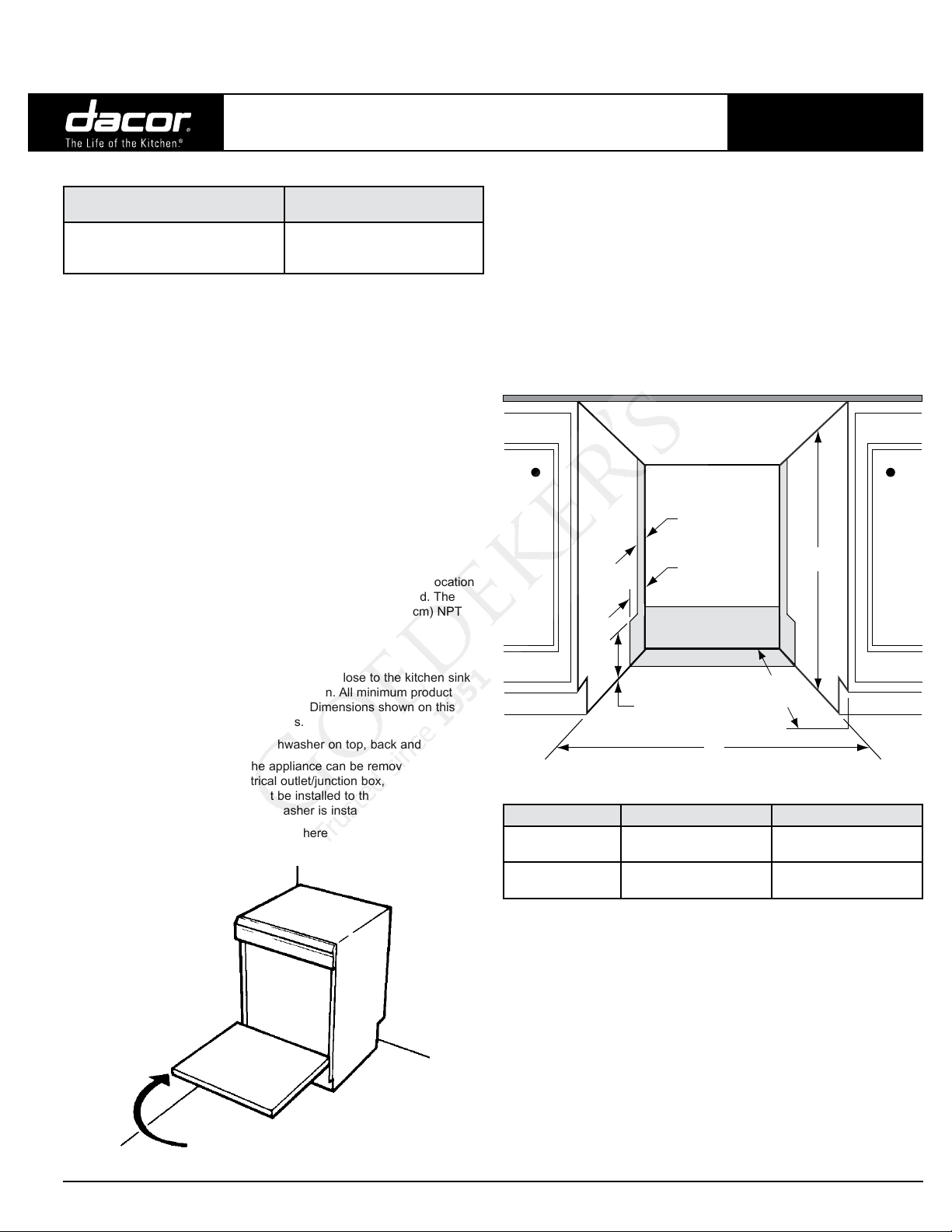
Location Specifications
■ Install in a location with convenient access, close to the kitchen sink
for easy water supply and drain connection. All minimum product
dimensions must be met or exceeded. Dimensions shown on this
page provide the required clearances.
■ The cabinet must enclose the dishwasher on top, back and sides.
■ Plan the installation so that the appliance can be removed easily if
service is required. The electrical outlet/junction box, water supply
valve and drain connection must be installed to the right or left of the
cutout and accessible when dishwasher is installed.
■ If dishwasher is installed in a corner, there must be a minimum
clearance of 2” (5.1 cm) from the side wall so the door can open. See
diagram.
2” (5.1 cm) min.
clearance
24”
5 3/8”
(13.6 cm)
DISHWASHER CUTOUT - FRONT VIEW
Model (E) Cutout Width (F) Cutout Height
RDW24I*
RDW24S** 24” (61.0 cm)
*If installing model RDWH24I in a 24” wide cutout installation of a trim kit
(Dacor PN 106925) is required to fill the space between the edge of the
cutout and the dishwasher.
** If the height of the existing cutout is too low:
■ Check to see if the cabinet face can be trimmed at the top. In many
cases, when a non-standard size dishwasher has been installed
previously, there is enough room inside the cabinet once the cabinet
face is modified.
■ The dishwasher can be shortened 1/4” (6.0 mm) by not installing the
plastic feet provided with the unit. Extra care must be taken if the feet
are not installed. Dacor is not responsible for floor damage during
installation.
■ The dishwasher can be shortened 1/4” (6.0 mm) by removing the trim
pieces that surround the wash compartment opening. NOTE: Doing
so will create a gap of 1/4” (6.0 mm) on the right and left side of the
door.
23 5/8” (60.0 cm) to
24” (61.0 cm)
(61.0 cm)
E
33 7/8” (86.0 cm) to
36” (91.4 cm)
34 3/8” (87.3 cm) to
36 1/2” (92.7 cm)
All specications subject to change without notice.
Phone: (800) 793-0093www.dacor.com
Page 3

Document # PG10-007
RDW24I, RDW24S
Revised 03/12/12 Page 3/3
Renaissance 24” Wide
Built-In Dishwasher
Drain Specifications
IMPORTANT: Should a drain hose longer than the one provided be
required, use a hose extension approved for detergents and high
temperature water. Total drain hose length (including factory installed
hose) must not exceed 10 feet. (304.8 cm) from the top of the drain loop
on the back of the unit. Joints and joint tubes must have a minimum inside
diameter of 7/8” (2.2 cm).
■ The drain hose supplied with the dishwasher must be connected to
a minimum 1/2” inside diameter drain connection. The drain hose is
equipped with a cone-shaped connector on the end that is ready to be
cut to the desired drain connection size. Only a clamp (not provided)
is required. It fits drain connections with an internal diameter of 1/2,
5/8, 3/4 and 7/8 inches (1.3, 1.6, 1.8 and 2.2 cm).
■ You must install an air gap in the drain system if required by local
codes. Plan for the air gap in the sink or countertop area adjacent to
the dishwasher. A section of drain hose (not provided) needs to be
installed from the air gap to the waste disposer inlet or waste tee. See
below.
■ If an air gap is not required, the drain hose must be installed to a
disposer inlet or waste tee above the sink trap in the household
plumbing.
■ For proper drainage, the drain line connection must be a minimum
of 20” (50.8 cm) above the bottom of the dishwasher. No part of the
drain hose can be lower than the disposer or waste tee connection or
higher than 35” (88.9 cm) from the bottom of the dishwasher.
PLANNING
GUIDE
Custom Panel/Handle for Model RDW24I
■ The custom panel mounting screws are provided with the dishwasher.
Follow the panel dimensions below to ensure that the custom overlay
panel will fit properly.
■ The handle and handle mounting hardware are not included with
model RDW24I. A handle designed for use with an appliance should
produce satisfactory results. Do not use a knob or handle attached
by a single fastener. Instead use a handle with a larger D-style
pull. The panel craftsman must determine and obtain the proper
handle fasteners for the application. Handle screw heads must be
countersunk into the panel before panel installation.
(G) Height (H) Width (J) Thickness
30 1/8” (76.5 cm) 23 3/4” (60.3 cm)* 3/4” (1.9 cm) min.
* Based on 24” (61.0 cm) wide cutout. Recommended panel width is 1/4”
(6.4 mm) less than cutout width.
IMPORTANT: If the door panel weighs more than 15 pounds, you must
order the optional heavy duty door springs (Dacor PN 701385). Maximum
panel weight with heavy duty springs: 23 pounds.
20"
min.
EXAMPLE OF DRAIN CONNECTION WITHOUT AIR GAP
20"
min.
35"
max.
max.
G
CUSTOM PANEL
DIMENSIONS
H
J
35"
EXAMPLE OF DRAIN CONNECTION WITH AIR GAP
All specications subject to change without notice.
Phone: (800) 793-0093www.dacor.com
 Loading...