

Page 1
Installation Instructions
Modernist Microwave In-A-Drawer
DMR24M977WM, DMR24M977WM
DMR30M977WM, DMR30M977WM
™
Part No. 112242 Rev B
Page 2

Contents
Before You Begin… 3
Important 3
Customer-Service Information 4
If You Need Help… 4
Model and Serial Numbers 4
Before You Call for Service… 4
Important Safety Precautions 5
Related Equipment Safety 5
Grounding the Microwave In-A-Drawer™ 5
Installation Requirements 7
Checklist 7
Design Specications 8
Clearances and Dimensions 8
Installation 11
Preparing to Install the Microwave In-A-Drawer™ 11
Provided Material 11
Unpacking the Microwave In-A-Drawer™ 11
About the Electrical Outlet 12
Installing the Anti-Tip Block 12
Installing the Microwave In-A-Drawer™ 12
2
Page 3

Before You Begin…
Important
Installer
• For safety and to minimize problems, read this manual thoroughly before starting the installation.
• The installer shall ensure proper installation; the warranty does NOT cover product failure due
to improper installation.
• Remove all packing material before connecting the electrical supply.
• Observe all local codes in installing the oven.
• Leave this manual with the owner.
• Write the oven’s model/serial numbers in this manual for service/maintenance reference.
Owner
• Keep this manual for personal reference and for that of inspectors, service personnel, etc.
3
Page 4
Customer-Service Information
If You Need Help…
If you have questions or issues with installation, contact your Dacor® dealer or the Dacor customer-service team. If your Dacor microwave is under warranty, call Dacor Customer Assurance.
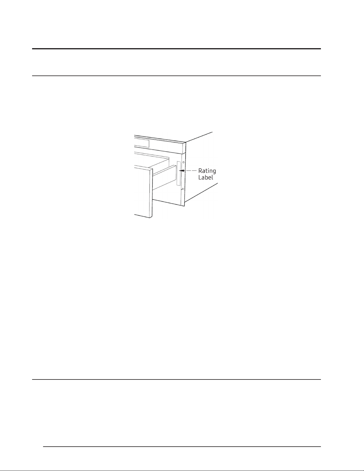
Have the microwave’s model/serial numbers available when you call.
These numbers are on the rating label, which is on the right-hand side of the chassis face. To
view the label: On the control panel, press Open. The drawer opens to reveal the label.
Dacor Customer Assurance
Phone: 800-793-0093 x2813 (USA, Canada)
Mon – Fri, 5:00 a.m. – 5:00 p.m. pacic time
Website
www.dacor.com/customer-care/contact-us
All specications may change without notice. Dacor assumes no liability for such changes.
© 2017 Dacor. All rights reserved.
Before You Call For Service…
Read the BEFORE YOU CALL and operating instruction sections in the User Manual. It may save
you time and money. The list includes common issues that are not caused by defective workmanship or material.
See the warranty information in your Use Manual for Dacor’s toll-free service number and address. Use the contact information if need to speak to a Dacor representative about warranty
and mechanical issues and to order parts.
4
Page 5
Important Safety Precautions
Related Equipment Safety
Remove all tape and packaging before using the microwave. Dispose of the packaging after
unpacking the oven. Do not let children play with the packing material. Do not modify the oven
(e.g., remove panels, wire covers, screws).
DANGER—ELECTRIC-SHOCK HAZARD
• To avoid risk of electrical shock, personal injury, or death; verify your appliance is grounded
according to local codes, or in their absence, with the National Electrical Code (NEC). ANSI/
NFPA 70-latest edition.
• To avoid severe personal injury and possibly death, the electricity must be off while the electrical connections are made.
WARNING—MOVING HAZARD
To avoid risk of severe personal injury; this appliance requires two or more people while handling and moving. Use of appliance moving devices is recommended.
WARNING
Never let anyone climb, sit, stand, hang, or put any kind of weight on the open oven drawer. Such
activity could result in property damage and personal injury.
Grounding the Microwave In-A-Drawer
The microwave has a 3-prong grounding plug that must be plugged into a grounded outlet.
If only a 2-prong wall outlet is available, the customer shall have it replaced with a properly
grounded 3-prong outlet.
• Do not remove the third (ground) prong from the power cord.
• Do not use an adapter plug.
• Do not use an extension cord. (If the power cord is too short, have a qualied electrician or
serviceman install an outlet near the appliance.)
• Do not use a Ground Fault Circuit Interrupter.
™
5
Page 6

Important Safety Precautions
Follow these precautions with exactness to avoid re or electrical shock that may cause property
damage, personal injury, or death.
WARNING
• Follow the information in this manual exactly to avoid re or electrical shock that may cause
property damage, personal injury, or death.
• Ensure the microwave is properly installed and grounded by a qualied technician.
• New branch-circuit installations (1996 NEC), mobile homes, RVs, or installations where local
codes prohibit grounding through the neutral conductor, require a 4-wire branch-circuit connection.
• Improper connection of aluminum house wiring to copper leads can cause an electrical hazard
or re. Use only connectors designed for joining copper to aluminum, and follow the manufacturer’s recommended procedure closely.
• Electricity must be off while the electrical connections are made. Failure to do so can
result in severe personal injury or death.
6
Page 7

Installation Requirements
Checklist
Use this checklist to ensure you complete the installation process properly and verify the oven’s
proper function:
• Before installing the oven, verify the cabinet dimensions are correct and the required electrical connections are present.
• See this manual’s content regarding Safety, Cabinet Dimensions, Removing Packaging, Electrical Installation, Testing the Installation and Customer Service.
• Team-lift the unit directly into the cabinet cutout.
• Ensure the electrical conduit reaches to the connection point properly.
• Slide the unit fully into place, while routing the electrical conduit correctly.
• With a Phillips screwdriver and supplied screws, anchor the oven to the cabinetry opening.
• Consult the complete installation instructions, and follow the other procedures listed, including verifying proper oven function.
• All product literature and accessories are supplied (may be wrapped or boxed) with the oven.
7
Page 8
Design Specications
Clearances and Dimensions
• The dimensions shown in Figures 2, 4, and 5 are minimums and must be used.
• The contact surface must be of solid, level, plywood construction strong enough to support
the oven’s weight (about 100 lbs).
• Locate the unit within easy access of the proper electrical outlet, or locate a new outlet. (See
About the Electrical Outlet, pg. 12.)
• The oven can be built into a cabinet or wall by itself or under any gas or electric wall oven.
• The clearance between the microwave drawer and a wall oven must be at least 2 in.
• The microwave drawer easily accommodates a 9” x 13” dish or bag of microwave popcorn.
• The microwave can be ush-mounted. (See the instructions included with the ush-mount
deector vent.)
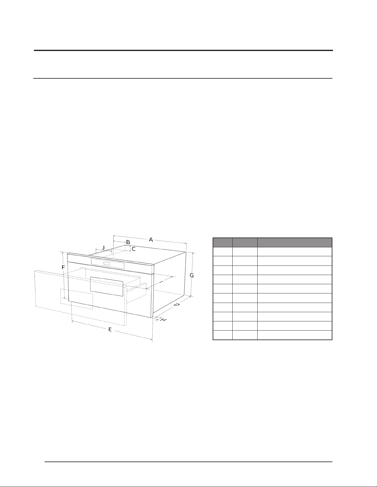
24” Drawer Dimensions
Figures 1 and 2 contain appliance dimensions that will help plan the drawer’s location.
Dim. Inches Description
A 21 5/8 Overall chassis width
B 4 11/16 Width of chassis notch
C 1 3/4 Height of chassis notch
D 21 7/8 Chassis depth
E 23 7/8 Microwave face width
F 15 7/8 Microwave face height
G 14 19/32 Chassis height
H 1 9/64 Door face thickness
I 15 Automatic drawer-open depth
J 4 Chassis notch width
8
Page 9
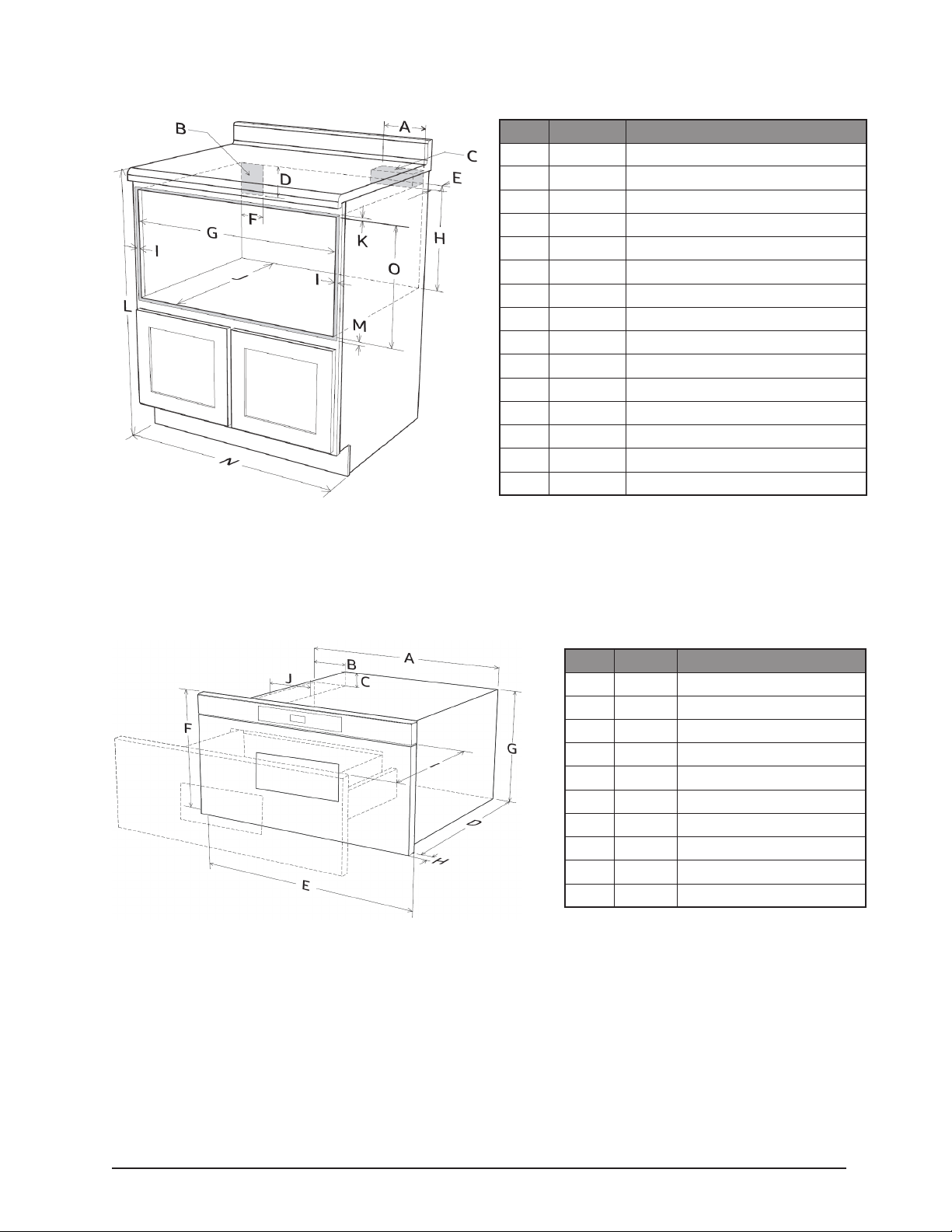
24” Drawer Dimensions, cont.
Dim. Inches Description
A 6 Anti-tip block length
B — Electrical outlet location
C — Anti-tip block
D 5 Outlet location height
E 3 1/2 Anti-tip block width
F 4 Outlet location width
G 22 1/8 Cutout width
H 14 13/16 Cutout oor to block bottom
I 7/8 Minimum overlap allowance (sides)
J 23 1/2 Minimum cutout depth
K 3/16 Minimum overlap allowance (top)
L 36 Nominal countertop height
M 1/8 Minimum overlap allowance (bottom)
N 24 Minimum cabinet width
O 15 9/16 Cutout height
30” Drawer Dimensions
Figures 3 and 4 contain appliance dimensions that will help plan the drawer’s location.
Dim. Inches Description
A 21 5/8 Overall chassis width
B 4 11/16 Width of chassis notch
C 1 3/4 Height of chassis notch
D 21 7/8 Chassis depth
E 30 Microwave face width
F 15 7/8 Microwave face height
G 14 19/32 Chassis height
H 1 9/64 Door face thickness
I 15 Automatic drawer-open depth
J 4 Chassis notch width
9
Page 10

30” Drawer Dimensions, cont.
Dim. Inches Description
A 6 Anti-tip block length
B — Electrical outlet location
C — Anti-tip block
D 5 Outlet location height
E 3 1/2 Anti-tip block width
F 4 Outlet location width
22 1/8 min.
G
28 7/16 max.
H 14 13/16 Cutout oor to block bottom
I 23/32 Minimum overlap allowance (sides)
J 23 1/2 Minimum cutout depth
K 3/16 Minimum overlap allowance (top)
L 36 Nominal countertop height
M 1/8 Minimum overlap allowance (bottom)
N 30 Minimum cabinet width
O 15 9/16 Cutout height
Cutout-opening width range
Dim. Inches Description
A 84 Nominal wall-cabinet height
B — Optional wall-oven cutout
C — Electrical outlet location
D 6 Anti-tip-block length
E — Anti-tip block
F 3 1/2 Anti-tip-block width
G 5 Outlet location height
H 4 Outlet location width
I 2 Min. distance between cutout openings
22 1/8 min.
J
28 7/16 max.
K 3/16 Minimum overlap allowance (top)
L 14 13/16 Cutout oor to block bottom
M 23/32 Minimum overlap allowance (sides)
N 23 1/2 Minimum cutout depth
O 15 9/16 Cutout height
P 1/8 Minimum overlap allowance (bottom)
Q 30 Minimum cabinet width
Cutout-opening width range
10
Page 11

Installation
Preparing to Install the Microwave In-A-Drawer
Phillips Screwdriver Drill
Provided Material
Panhead Screws (4) Literature Kit
™
Unpacking the Microwave In-A-Drawer
• Remove packing material from the drawer
(Do not remove the waveguide cover, which
is on the oven-chamber ceiling.)
• Remove the “features” sticker.
• Check for damage (e.g., loose/bent/misaligned components, damaged drawer seal,
dented surfaces).
• Report damage to your dealer or a Dacor
Authorized Servicer. Do not install/operate
a damaged appliance.
™
11
Page 12

Installation
About the Electrical Outlet
Installing the Anti-Tip Block
A 120 volt 60 Hz, AC only, 15 amp. or more protected electrical supply is required. It is preferable that the oven be on its own circuit.
The drawer has a 3-prong grounding plug that
must be plugged into a properly installed and
grounded outlet. If only a 2-prong outlet is
available, have a qualied electrician install a
proper outlet.
NOTE: Address any questions to a qualied
electrician or service technician.
This block keeps the oven from tipping forward
and possibly spilling hot foods and liquids.
It must be installed so its bottom is 14 13/16”
above the cutout oor.
The installer shall provide the anti-tip block.
(See pgs. 9 and 10 for specic placements.)
If the drawer is relocated, relocate the block
with it.
Installing the Microwave In-A-Drawer
1. Place the drawer in front of its cutout.
2. Plug in the power cord, and slide the unit
3. On the control panel, press Open. The draw-
4. Using the 4 holes as a template, predrill
™
into the cutout until the mounting ange
meets the cabinet face. (Do not pinch the
cord between the chassis and the wall.)
er opens, exposing the four anchor-screw
holes. (See the graphic at left.)
the cabinet with a 1/16” bit, then anchor the
drawer with the 4 provided screws.
12
Page 13

Instructions D’installation
Modernist Micro-Onde Tiroir
DMR24M977WM, DMR24M977WM
DMR30M977WM, DMR30M977WM
™
Page 14

Table des Matières
Avant de Commencer… 3
Important 3
Information Pour le Service à la Clientèle 4
Pour Obtener de L’aide… 4
Nombre de modèles et de séries 4
Before You Call for Service… 4
Important Précautions de Sécurité 5
Related Equipment Safety 5
Grounding the Microwave In-A-Drawer™ 5
Conditions D’installation 7
Liste de Contrôle 7
Les Spécications de Conception 8
Clearances and Dimensions 8
Installation 11
Preparing to Install the Microwave In-A-Drawer™ 11
Provided Material 11
Unpacking the Microwave In-A-Drawer™ 11
About the Electrical Outlet 12
Installing the Anti-Tip Block 12
Installing the Microwave In-A-Drawer™ 12
14
Page 15

Before You Begin…
Important
Installer
• For safety and to minimize problems, read this manual thoroughly before starting the installation.
• The installer shall ensure proper installation; the warranty does NOT cover product failure due
to improper installation.
• Remove all packing material before connecting the electrical supply.
• Observe all local codes in installing the oven.
• Leave this manual with the owner.
• Write the oven’s model/serial numbers in this manual for service/maintenance reference.
Owner
• Keep this manual for personal reference and for that of inspectors, service personnel, etc.
15
Page 16

Customer-Service Information
If You Need Help…
If you have questions or issues with installation, contact your Dacor® dealer or the Dacor customer-service team. If your Dacor microwave is under warranty, call Dacor Distinctive Service. Have
the microwave’s model/serial numbers available when you call.
Dacor Modernist Service (under-warranty repairs only)
Phone: 800-793-0093 x2822 (USA and Canada)
Mon – Fri, 6:00 a.m. – 5:00 p.m. pacic time
Dacor Customer Service
Phone: 800-793-0093 x2813 (USA and Canada)
Mon – Fri, 6:00 a.m. – 5:00 p.m. pacic time
Website
www.dacor.com
All specications may change without notice. Dacor assumes no liability for such changes.
© 2017 Dacor. All rights reserved.
Model and Serial Numbers
Before You Call For Service…
The model and serial numbers are on the rating label, which is on the right-hand side of the
chassis face. (See the graphic at left.)
To view the label:
On the control panel, press Open. The drawer
opens to reveal the label.
Read the BEFORE YOU CALL and operating instruction sections in your User Manual. It may save
you time and money. The list includes common issues that are not caused by defective workmanship or material.
See the warranty information in your Use Manual for Dacor’s toll-free service number and address. Use the contact information if need to speak to a Dacor representative about warranty
and mechanical issues and to order parts.
16
Page 17

Important Safety Precautions
Related Equipment Safety
Remove all tape and packaging before using the microwave. Dispose of the packaging after
unpacking the oven. Do not let children play with the packing material. Do not modify the oven
(e.g., remove panels, wire covers, screws).
DANGER—ELECTRIC-SHOCK HAZARD
• To avoid risk of electrical shock, personal injury, or death; verify your appliance is grounded
according to local codes, or in their absence, with the National Electrical Code (NEC). ANSI/
NFPA 70-latest edition.
• To avoid severe personal injury and possibly death, the electricity must be off while the electrical connections are made.
WARNING—MOVING HAZARD
To avoid risk of severe personal injury; this appliance requires two or more people while handling and moving. Use of appliance moving devices is recommended.
WARNING
Never let anyone climb, sit, stand, hang, or put any kind of weight on the open oven drawer. Such
activity could result in property damage and personal injury.
Grounding the Microwave In-A-Drawer
The microwave has a 3-prong grounding plug that must be plugged into a grounded outlet.
If only a 2-prong wall outlet is available, the customer shall have it replaced with a properly
grounded 3-prong outlet.
• Do not remove the third (ground) prong from the power cord.
• Do not use an adapter plug.
• Do not use an extension cord. (If the power cord is too short, have a qualied electrician or
serviceman install an outlet near the appliance.)
• Do not use a Ground Fault Circuit Interrupter.
™
17
Page 18

Important Safety Precautions
Follow these precautions with exactness to avoid re or electrical shock that may cause property
damage, personal injury, or death.
WARNING
• Follow the information in this manual exactly to avoid re or electrical shock that may cause
property damage, personal injury, or death.
• Ensure the microwave is properly installed and grounded by a qualied technician.
• New branch-circuit installations (1996 NEC), mobile homes, RVs, or installations where local
codes prohibit grounding through the neutral conductor, require a 4-wire branch-circuit connection.
• Improper connection of aluminum house wiring to copper leads can cause an electrical hazard
or re. Use only connectors designed for joining copper to aluminum, and follow the manufacturer’s recommended procedure closely.
• Electricity must be off while the electrical connections are made. Failure to do so can
result in severe personal injury or death.
18
Page 19

Installation Requirements
Checklist
Use this checklist to ensure you complete the installation process properly and verify the oven’s
proper function:
• Before installing the oven, verify the cabinet dimensions are correct and the required electrical connections are present.
• See this manual’s content regarding Safety, Cabinet Dimensions, Removing Packaging, Electrical Installation, Testing the Installation and Customer Service.
• Team-lift the unit directly into the cabinet cutout.
• Ensure the electrical conduit reaches to the connection point properly.
• Slide the unit fully into place, while routing the electrical conduit correctly.
• With a Phillips screwdriver and supplied screws, anchor the oven to the cabinetry opening.
• Consult the complete installation instructions, and follow the other procedures listed, including verifying proper oven function.
• All product literature and accessories are supplied (may be wrapped or boxed) with the oven.
19
Page 20

Design Specications
Clearances and Dimensions
• The dimensions shown in Figures 2, 4, and 5 are minimums and must be used.
• The contact surface must be of solid, level, plywood construction strong enough to support
the oven’s weight (about 100 lbs).
• Locate the unit within easy access of the proper electrical outlet, or locate a new outlet. (See
About the Electrical Outlet, pg. 11.)
• The oven can be built into a cabinet or wall by itself or under any gas or electric wall oven.
• The clearance between the microwave drawer and a wall oven must be at least 2 in.
• The microwave drawer easily accommodates a 9” x 13” dish or bag of microwave popcorn.
• The microwave can be ush-mounted. (See the instructions included with the ush-mount
deector vent.)
24” Drawer Dimensions
Figures 1 and 2 contain appliance dimensions that will help plan the drawer’s location.
Dim. Inches Description
A 21 5/8 Overall chassis width
B 4 11/16 Width of chassis notch
C 1 3/4 Height of chassis notch
D 21 7/8 Chassis depth
E 23 7/8 Microwave face width
F 15 7/8 Microwave face height
G 14 19/32 Chassis height
H 1 9/64 Door face thickness
I 15 Automatic drawer-open depth
J 4 Chassis notch width
20
Page 21

24” Drawer Dimensions, cont.
Dim. Inches Description
A 6 Anti-tip block length
B — Electrical outlet location
C — Anti-tip block
D 5 Outlet location height
E 3 1/2 Anti-tip block width
F 4 Outlet location width
G 22 1/8 Cutout width
H 14 13/16 Cutout oor to block bottom
I 7/8 Minimum overlap allowance (sides)
J 23 1/2 Minimum cutout depth
K 3/16 Minimum overlap allowance (top)
L 36 Nominal countertop height
M 1/8 Minimum overlap allowance (bottom)
N 24 Minimum cabinet width
O 15 9/16 Cutout height
30” Drawer Dimensions
Figures 3 and 4 contain appliance dimensions that will help plan the drawer’s location.
Dim. Inches Description
A 21 5/8 Overall chassis width
B 4 11/16 Width of chassis notch
C 1 3/4 Height of chassis notch
D 21 7/8 Chassis depth
E 30 Microwave face width
F 15 7/8 Microwave face height
G 14 19/32 Chassis height
H 1 9/64 Door face thickness
I 15 Automatic drawer-open depth
J 4 Chassis notch width
21
Page 22

30” Drawer Dimensions, cont.
A 6 Anti-tip block length
B — Electrical outlet location
C — Anti-tip block
D 5 Outlet location height
E 3 1/2 Anti-tip block width
F 4 Outlet location width
22 1/8 min.
G
28 7/16 max.
H 14 13/16 Cutout oor to block bottom
I 23/32 Minimum overlap allowance (sides)
J 23 1/2 Minimum cutout depth
K 3/16 Minimum overlap allowance (top)
L 36 Nominal countertop height
M 1/8 Minimum overlap allowance (bottom)
N 30 Minimum cabinet width
O 15 9/16 Cutout height
Cutout-opening width range
A 84 Nominal wall-cabinet height
B — Optional wall-oven cutout
C — Electrical outlet location
D 6 Anti-tip-block length
E — Anti-tip block
F 3 1/2 Anti-tip-block width
G 5 Outlet location height
H 4 Outlet location width
I 2 Min. distance between cutout openings
22 1/8 min.
J
28 7/16 max.
K 3/16 Minimum overlap allowance (top)
L 14 13/16 Cutout oor to block bottom
M 23/32 Minimum overlap allowance (sides)
N 23 1/2 Minimum cutout depth
O 15 9/16 Cutout height
P 1/8 Minimum overlap allowance (bottom)
Q 30 Minimum cabinet width
Cutout-opening width range
22
Page 23

Installation
Preparing to Install the Microwave In-A-Drawer
Phillips Screwdriver Drill
Provided Material
Panhead Screws (4) Literature Kit
™
Unpacking the Microwave In-A-Drawer
• Remove packing material from the drawer
(Do not remove the waveguide cover, which
is on the oven-chamber ceiling.)
• Remove the “features” sticker.
• Check for damage (e.g., loose/bent/misaligned components, damaged drawer seal,
dented surfaces).
• Report damage to your dealer or a Dacor
Authorized Servicer. Do not install/operate
a damaged appliance.
™
23
Page 24

Installation
About the Electrical Outlet
Installing the Anti-Tip Block
A 120 volt 60 Hz, AC only, 15 amp. or more protected electrical supply is required. It is preferable that the oven be on its own circuit.
The drawer has a 3-prong grounding plug that
must be plugged into a properly installed and
grounded outlet. If only a 2-prong outlet is
available, have a qualied electrician install a
proper outlet.
NOTE: Address any questions to a qualied
electrician or service technician.
This block keeps the oven from tipping forward
and possibly spilling hot foods and liquids.
It must be installed so its bottom is 14 13/16”
above the cutout oor.
The installer shall provide the anti-tip block.
(See pgs. 9 and 10 for specic placements.)
If the drawer is relocated, relocate the block
with it.
Installing the Microwave In-A-Drawer
1. Place the drawer in front of its cutout.
2. Plug in the power cord, and slide the unit
3. On the control panel, press Open. The draw-
4. Using the 4 holes as a template, predrill
™
into the cutout until the mounting ange
meets the cabinet face. (Do not pinch the
cord between the chassis and the wall.)
er opens, exposing the four anchor-screw
holes. (See the graphic at left.)
the cabinet with a 1/16” bit, then anchor the
drawer with the 4 provided screws.
24
Page 25

Page 26

Page 27

Page 28

Dacor ∙ 14425 Clark Avenue, City of Industry, CA 91745 ∙ Phone: (800) 793-0093 ∙ Fax: (626) 403-3130 ∙ www.dacor.com
 Loading...