

Page 1

Modernist Microwave In-A-Drawer
Installation Instructions
Model Numbers:
DMR24M977WM, DMR24M977WS,
DMR30M977WM, DMR30M977WS
™
Table of Contents
Important Safety Instructions ..........................1
What You Need to Know About Safety
Instructions .............................................1
Safety Symbols and Labels .........................1
Installation Requirements ................................2
Important Notes To The Installer .................2
Important Notes To The Consumer ............... 2
Grounding Instructions ............................... 2
Design Specifications ...................................3-5
Clearances and Dimensions .........................3
Part No. 112242 Rev A
24" Drawer Measurements .......................... 3
30" Drawer Measurements .......................... 4
Anti-tip Block ............................................ 5
Installation Instructions ................................5-6
Verifying Package Contents ......................... 5
Electrical Outlet ......................................... 5
Drawer Installation ....................................6
Care, Cleaning and Maintenance ....................... 6
Before You Call for Service ............................... 6
TINSKB243MRR0
Page 2
IMPORTANT SAFETY INSTRUCTIONS
WARNING
• If the information in this manual is not followed exactly, a re or electrical shock may result that could cause
property damage, personal injury or death.
• To reduce the risk of tipping, the Microwave In-A-Drawer™ must be secured by a properly installed anti-tip block.
• This drawer must be electrically grounded in accordance with local codes.
• Make sure the wall coverings and the cabinets around the drawer can withstand the heat generated by the
microwave.
• Never leave children alone or unattended in the area where a microwave is in use. Never leave the
drawer open when the microwave is unattended.
• Stepping, leaning or sitting on the drawer may result in serious injuries and can also cause damage to the
Microwave In-A-Drawer™.
• Do not use the drawer as a storage space. Doing so creates a potentially hazardous situation.
• Check that the time-of-day is on the display. If not, touch STOP/C L E AR to prevent unintended use.
WHAT YOU NEED TO KNOW ABOUT
SAFETY INSTRUCTIONS
Warnings and Important Safety Instructions appearing in
this guide are not meant to cover all possible conditions
and situations that may occur. Always use common
sense, caution and care when installing, maintaining or
operating this appliance.
Always contact Dacor® about problems or conditions you
do not understand.
SAFETY SYMBOLS AND LABELS
DANGER
Immediate hazards that WILL result in severe
personal injury or death.
WARNING
Hazards or unsafe practices that COULD result in
severe personal injury or death.
Installer: Leave these instructions with the appliance.
Customer: Read and keep these installation instructions
for reference.
If you have any questions, call:
Dacor Customer Assurance
1-800-793-0093 x2813 (U.S.A. and Canada)
Monday — Friday 5:00 am to 5:00 pm Pacic Time
Web site: www.dacor.com/customer-care/contact-us
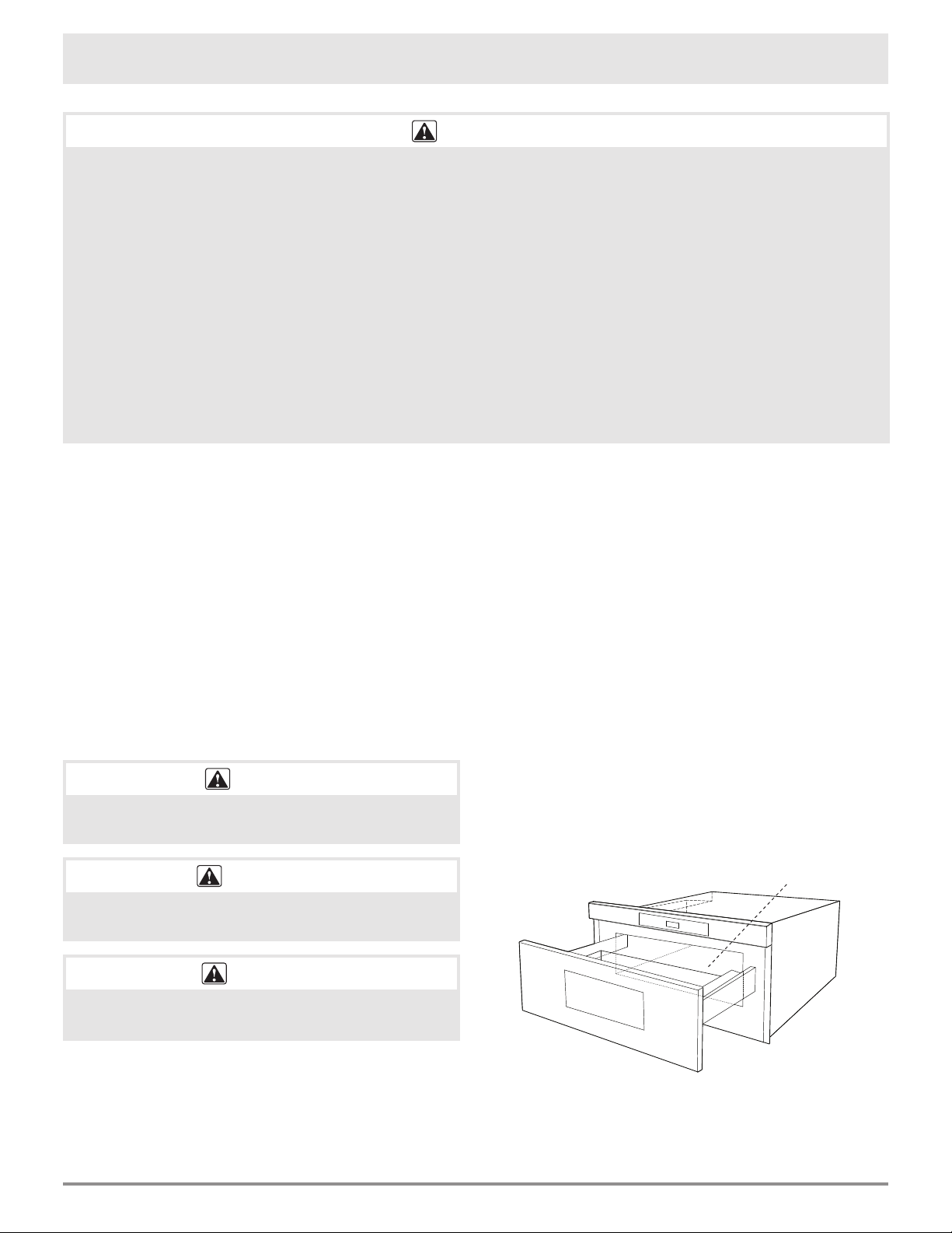
Before you call, have available the model and
serial numbers, which you can view by opening the
drawer fully and reading the rating label on the
oven-cavity floor just past the drawer's rear panel.
Rating Label (cavity floor)
CAUTION
Hazards or unsafe practices that COULD result in
minor personal injury or property damage.
E1
Page 3
Installation Requirements
The importance of the proper installation of your new
appliance cannot be overemphasized. Installation should
be done by a qualied installer.
GROUNDING INSTRUCTIONS
Before you begin the installation process, read this entire
installation instruction manual. It contains information
necessary for proper, safe installation.
Any questions or problems with the installation should
be directed to your Dacor dealer or the Dacor Customer
Service Department at 800.793.0093. You can also visit
our web site at www.Dacor.com.
IMPORTANT NOTES TO THE
INSTALLER
• Read all of the installation instructions before
installing the Microwave In-A-Drawer™.
• Remove all packing material before connecting
the electrical supply.
• Observe all governing codes and ordinances.
• Be sure to leave these instructions with the
consumer.
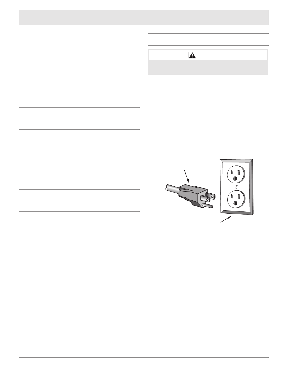
WARNING
Improper use of the grounding plug can result in a
risk of electric shock.
This appliance is equipped with a three-prong grounding
plug for your protection against possible electric
shock hazards. It must be plugged into a grounded
wall receptacle. If only a two-prong wall receptacle
is available, it is the responsibility of the customer to
have it replaced with a properly grounded three-prong
wall receptacle. Do not under any circumstances,
cut or remove the third (ground) prong from the
power cord. Do not use an adapter plug. Do not use
an extension cord. If the power supply cord is too short,
have a qualied electrician or serviceman install an outlet
near the appliance. Do not use a Ground Fault Circuit
Interrupter.
Power supply cord with
three-prong grounding plug
IMPORTANT NOTES TO THE
CONSUMER
Keep these instructions with your use & care manual for
future reference.
• When using any microwave oven generating
heat, there are certain safety precautions you
should follow, that are listed in the use & care
manual. Read the use and care manual and follow
all safety precautions carefully.
• Be sure your Microwave In-A-Drawer™ is installed
and grounded properly by a qualied installer or
service technician.
For SAFETY CONSIDERATIONS do not install the drawer
in any combustible cabinetry, which is not in accord with
the stated clearances and dimensions on pages 3, 4 and
5. See Figure 2 (for 24") or Figures 4 and 5 (for 30").
Grounding type wall receptacle
(ground fault circuit not allowed)
E2
Page 4
Design Specifications
A
B
C
L
K
J
D
E
G
H
F
I
M
M
N
O
P
Q
A
B
C
F
I
D
H
G
E
J
CLEARANCES AND
DIMENSIONS
• Dimensions that are shown in Figures 2, 4
and 5 must be used. Given dimensions provide
minimum clearance. Locate the electrical outlet
in the shaded area in the upper left-hand corner
of the cutout. See Figure 8.
• The contact surface must be solid and level.
Pay special attention to the oor on which the
drawer will sit. The oor of the opening should be
constructed of plywood strong enough to support
the weight of the unit (about 100 pounds).
• Check the location where the drawer will be
installed for proper electrical supply.
• Your oven can be built into a cabinet or wall by
itself or under any gas or electric wall oven.
• Be sure that the clearance of the oor between
the wall oven and the drawer is a minimum of 2".
• The
Microwave In-A-Drawer™ interior will easily
accommodate a 9” x 13” oblong dish or bag of
microwave popcorn.
• The Microwave In-A-Drawer™ can also be
mounted ush. Please see instructions for ush
mounting included with the ush mount deector
vent.
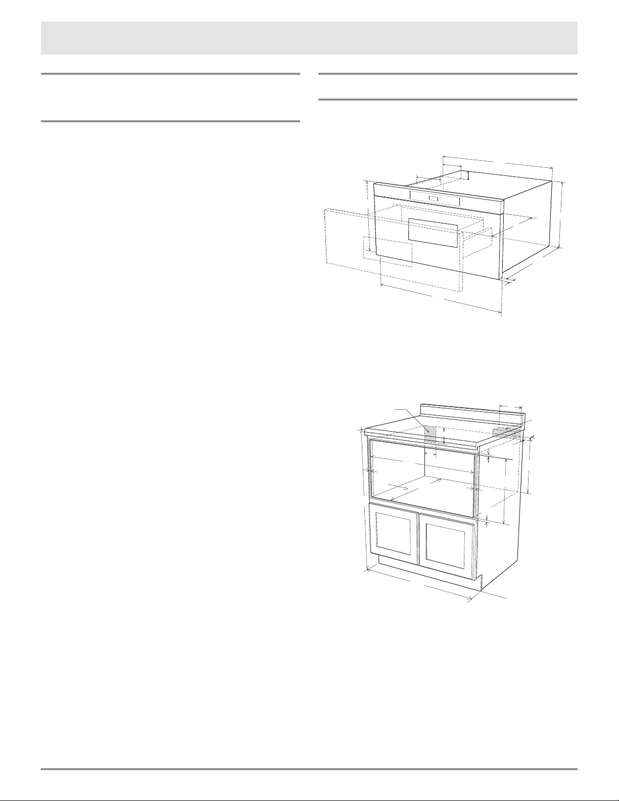
24" DRAWER MEASUREMENTS
Figures 1 and 2 contain many Microwave In-A-Drawer™
measurements for reference when planning the drawer’s
location.
A
C
I
H
19
/32"
9
/64" door thickness
A
G
D
C
E
Figure 1
A. 21 5/8"
B. 4
C. 1
D. 21 7/8"
E. 23 7/8"
J
F
B
E
F. 15 7/8"
11
/16"
3
/4"
G. 14
H. 1
I. 15" auto drawer opening
J. 4"
B
D
F
G
I
N
L
Figure 2
A. 6"
B. Electrical outlet location
C. Anti-tip block
D. 5"
E. 3 1/2"
F. 4"
G. 22 1/8" opening
H. 14 13/16" to bottom
of anti-tip block
J
0
I. Allow
J. 23 1/2" minimum depth
K. Allow 3/16" minimum overlap
L. 36" nominal countertop height
M. Allow 1/8" minimum overlap
N. Floor must support 100 lbs.
O. *24" cabinet minimum
P. 15 9/16" opening
NOTE: Open Top Cabinet illustrated
K
I
M
7
/8" minimum overlap
H
P
E3
Page 5
Design Specifications
G
A
B
C
L
K
J
D
E
G
H
F
I
M
M
N
O
P
Q
A
B
C
F
I
D
H
G
E
J
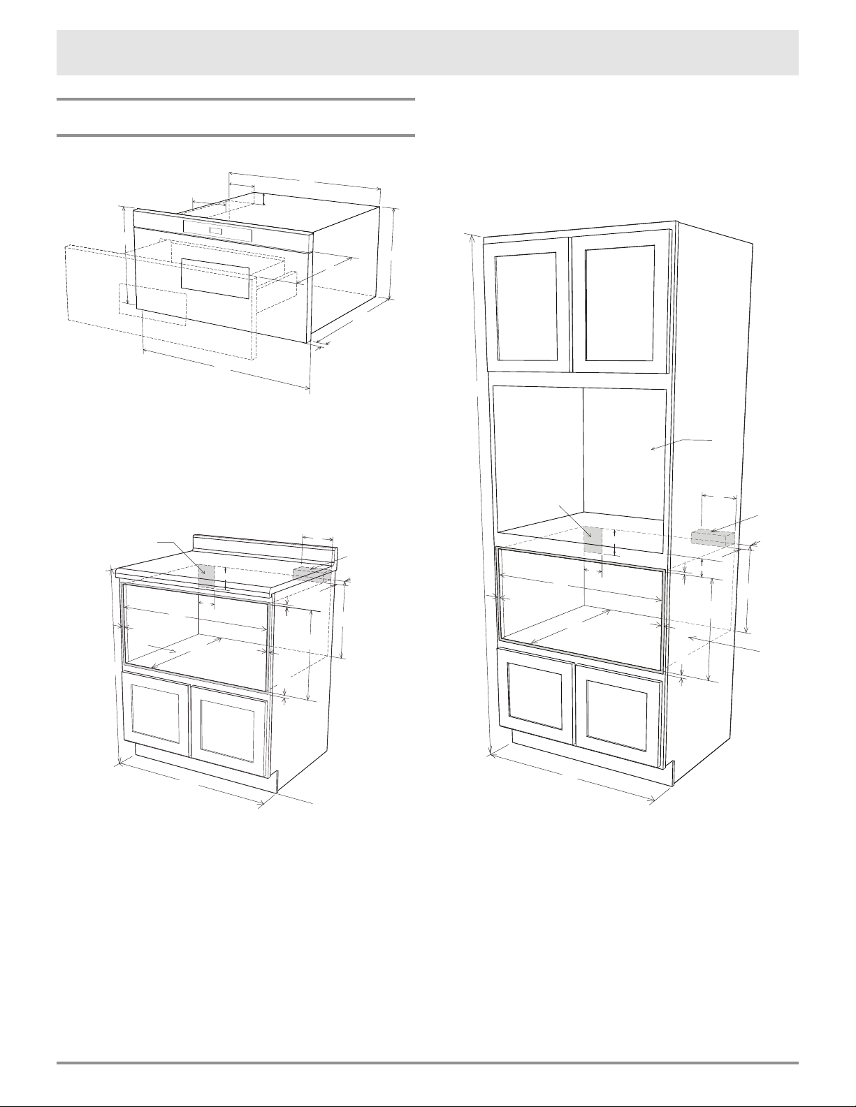
30" DRAWER MEASUREMENTS
A
C
I
H
A
C
K
P
M
E
H
Figure 3
F
A. 21 5/8"
B. 4 11/16"
C. 1 3/4"
D. 21 7/8"
E. 30"
I
N
L
E
B
F. 15 7/8"
J
G. 14 19/32"
H. 1 9/64" door thickness
I. 15" auto drawer opening
J. 4"
B
G
D
F
J
I
Figures 3, 4 and 5 contain the appliance and cutout
measurements for reference when planning the drawer’s
location.
G
D
A
B
C
G
H
J
M
N
M
D
E
F
I
K
P
L
O
Q
Figure 4
0
A. 6"
B. Electrical outlet location
C. Anti-tip block
D. 5"
E. 3 1/2"
F. 4"
G. 22 1/8" minimum
28 7/16" maximum
H. 14 13/16" to bottom
of anti-tip block
I. Allow 23/32" minimum overlap
J. 23 1/2" minimum depth
K. Allow 3/16" minimum overlap
L. 36" nominal countertop height
M. Allow 1/8" minimum overlap
N. Floor must support 100 lbs.
O. *30" cabinet minimum
P. 15 9/16" opening
NOTE: Open Top
Cabinet illustrated
Figure 5
A. 84" nominal wall cabinet
B. Optional wall oven cutout
illustrated in sketch
C. Electrical outlet location
D. 6"
E. Anti-tip block
F. 3 1/2"
G. 5"
H. 4"
I. 2" minimum
J. 22 1/8” minimum
28 7/16” maximum
E4
R
K. Allow 3/16" overlap
L. 14 13/16" to bottom
of anti-tip block
M. Allow 23/32" minimum overlap
N. 23 1/2" minimum depth
O. 15 9/16" opening
P. Allow 1/8" minimum overlap
Q. Floor must support 100 lbs.
R. 30" cabinet minimum
Page 6

Design Specifications
anti-tip
block
(6")
ANTI-TIP BLOCK
NORMAL INSTALLATION STEPS
penetrate the dry wall and are properly secured into the
base material underneath so that the block is totally
stable. When fastening, be sure that the screws do not
penetrate electrical wiring or plumbing.
ANTI-TIP BLOCK INSTALLATION INSTRUCTIONS
To reduce the risk of tipping the drawer, the anti-tip
block must be properly installed 14
cutout. The 6" anti-tip block must be provided by the
installer. See Figures 2 and 6 for (24") or Figures 4, 5,
and 6 (for 30"). The anti-tip block prevents serious injury
that might result from spilled hot liquids.
If the drawer is moved to a different location later, the
anti-tip block must also be moved and installed. When
installed to the wall, make sure that the screws completely
13
/16
" above the oor
Installation Instructions
VERIFYING PACKAGE
CONTENTS
• Remove all packing materials from inside the
drawer. DO NOT REMOVE THE WAVEGUIDE
COVER, which is located inside, on the ceiling of
the Microwave In-A-Drawer™.
Sealing
Surface
Waveguide
Cover
(6")
anti-tip
block
Figure 6
ELECTRICAL OUTLET
electrical outlet
location
5"
4"
Figure 8
• Remove the feature sticker, if there is one. Check
the drawer for any damage, such as misaligned or
bent drawer, damaged drawer seals and sealing
surfaces, broken or loose drawer guides and
dents inside the cavity or on the front side of the
drawer. If there is any damage, do not install or
operate the Microwave In-A-Drawer™ and contact
your dealer or a DACOR AUTHORIZED SERVICER.
Sealing
Surface
Oven
Cavity
Figure 7
The electrical requirements are a 120 volt 60 Hz, AC
only, 15 amp. or more protected electrical supply. It
is recommended that a separate circuit serving only
this appliance be provided.
The drawer is equipped with a 3-prong grounding
plug. It must be plugged into a wall receptacle that
is properly installed and grounded. Should you only
have a 2-prong outlet, have a qualied electrician
install a correct wall receptacle.
NOTE:
If you have any questions about the grounding or
electrical instructions, consult a qualied electrician
or service person.
E5
Page 7

Installation Instructions
DRAWER INSTALLATION
Figure 9A
1. Place the drawer adjacent to the
wall or cabinet opening. Plug
the power supply cord into the
electrical outlet.
2. Carefully guide the unit into the
prepared opening. Avoid pinching
the cord between the appliance
and the wall.
Parts Supplied
4 Screws
Figure 9B
CARE, CLEANING AND
MAINTENANCE
Refer to the use & care manual for cleaning instructions.
BEFORE YOU CALL FOR
SERVICE
Read the BEFORE YOU CALL and operating instruction
sections in your use & care manual. It may save
you time and expense. The list includes common
occurrences that are not the result of defective
workmanship or materials in this microwave.
Refer to the warranty in your use & care manual
for Dacor’s toll-free service number and address.
Please call or write if you have inquiries about your
microwave product and/or need to order parts.
3. Slide the drawer in until the mounting ange is
ush with the face of the cabinet.
4. Open the drawer. Using the 4 holes on the drawer
as a template, predrill the cabinet using a
drill bit. See Figure 9A.
5. Secure the drawer with the 4 screws supplied.
See Figure 9B.
1
/16
"
E6
Page 8

Modernist Micro-Onde Tiroir
Directives D’installation
Numéros de Modèle:
DMR24M977WM, DMR24M977WS,
DMR30M977WM, DMR30M977WS
™
Table des matières
Importantes consignes de sécurité ................... 8
Ce que vous devez savoir au sujet des
consignes de sécurité ............................... 8
Symboles et étiquettes de sécurité ............. 8
Conditions d’installation .................................. 9
Notes importantes à l’installateur ................ 9
Notes importantes au client ....................... 9
Instructions de mise à la terre .................... 9
Caractéristiques techniques ......................10-11
Dégagements et dimensions .....................10
Mesures pour le tiroir de 24 po ..................10
Mesures pour le tiroir de 30 po ..................11
Bloc anti-basculement ..............................12
Directives d’installation ............................12-13
Vérification du contenu de l’emballage ........12
Prise électrique .......................................12
Installation du tiroir .................................13
Entretien et nettoyage ..................................13
Avant d’appeler le service de réparations .........13
Page 9

IMPORTANTES CONSIGES DE SÉCURITÉ
MISE EN GARDE
• Si l’information contenue dans ce manuel n’est pas exactement suivie, un incendie ou une décharge électrique
pourrait causer des dommages matériels, des blessures personnelles ou la mort.
• Pour réduire le risque de basculement, le four Microwave In-A-Drawer™ doit être xé à l’aide d’un bloc anti-
basculement correctement installé.
• Ce tiroir doit être mis à la terre en conformité avec les codes locaux.
• Vérier que les revêtements muraux et les armoires autour du tiroir peuvent supporter la chaleur générée par le
four à micro-ondes.
• Ne jamais laisser des enfants seuls ou sans surveillance dans un endroit où un four à micro-ondes
fonctionne. Ne jamais laisser le tiroir ouvert quand le four est sans surveillance.
• Le fait de monter, de s’appuyer ou de s’asseoir sur le tiroir peut entraîner de sérieuses blessures et peut également
endommager le four Microwave In-A-Drawer™.
• Ne pas utiliser la cavité comme espace de rangement. Cela crée une situation potentiellement dangereuse.
• Vérier que l’heure s’afche. Sinon, appuyer sur STOP/CLEAR pour empêcher une utilisation non prévue.
CE QUE VOUS DEVEZ SAVOIR AU SUJET
DES CONSIGNES DE SÉCURITÉ
Les mises en garde et les importantes consignes de sécurité
apparaissant dans ce manuel ne couvrent pas toutes les
conditions et situations possibles. Il faut exercer son bon
sens, de la prudence et de l’attention en installant en
entretenant et en utilisant cet appareil.
Toujours communiquer avec Dacor® au sujet des
problèmes ou des conditions que vous ne comprenez
pas.
SYMBOLES ET ÉTIQUETTES DE SÉCURITÉ
DANGER
Risques immédiats qui AURONT pour
conséquence de sévères blessures ou la mort.
MISE EN GARDE
Risques ou comportements non sécuritaires
qui POURRAIENT avoir pour conséquence
de sévères blessures ou la mort.
Installateur : Laisser ces directives avec l’appareil.
Client : Lisez et conservez ces instructions d’installation
pour référence.
Si vous avez des questions, appelez :
Assurance client Dacor
1-800-793-0093 poste 2813 (É.-U. et Canada)
Lundi à vendredi, 5 h à 17 h Heure du Pacifique
site Web: www.dacor.com/customer-care/contact-us
Avant d'appeler, disposez des numéros de modèle et
de série qui vous pouvez afficher en ouvrant
entièrement le tiroir et en lisant la note étiquette sur
le plancher de la cavité du four juste après le panneau
arrière du tiroir.
Caractéristiques nominales
(plancher du c
hâssis)
ATTENTION
Risques ou comportements non sécuritaires
qui POURRAIENT avoir pour conséquence des
blessures mineures ou des dommages matériels.
F8
Page 10

Conditions d’installation
Il ne faut pas sous-estimer l’importance de l’installation de
votre nouvel appareil. Un installateur qualié doit procéder
à l’installation.
Avant de commencer l’installation, de lire la totalité des
directives d’installation. Il contient des renseignements
nécessaires pour un bon, la sécurité de l’installation.
Il faut acheminer les questions ou les problèmes concernant
l’installation à votre détaillant Dacor ou au service
assistance à la clientèle de Dacor au 800.793.0093. Vous
pouvez consulter aussi notre site Web à www.Dacor.com.
REMARQUES IMPORTANTES À
L’INSTALLATEUR
• Lire toutes les directives d’installation avant d’installer
le four Microwave In-A-Drawer™.
• Retirer tous les matériaux d’emballage avant de
connecter au secteur.
• Observer tous les codes et règlements en vigueur.
• Veiller à laisser ces directives au client.
INSTRUCTIONS POUR LA MISE À
LA TERRE
MISE EN GARDE
Un mauvais usage de la prise de terre peut causer des
décharges électriques.
Cet appareil est équipé d’une trois-fourche fondant la
prise pour votre protection contre des risques de choc
électrique possibles. Il doit être branché à une prise de
mise à la terre. Là où une prise murale de deux-fourche
standard est produite, il est de la responsabilité personnelle
et engagement du client pour le faire remplacer avec
une prise murale correctement fondée de trois-fourche.
Pas dans aucune circonstance, coupe ou enlever la
troisième fourche (de la terre) du cordon de secteur.
N’utilisez pas une prise d’adapteur. N’employez pas une
corde de prolongation. Si le cordon d’alimentation est trop
court, demander à un électricien ou un réparateur qualié
de poser une prise près de l’appareil. N’employez pas un
interrupteur moulu de circuit de défaut.
REMARQUES IMPORTANTES AU
CLIENT
Conserver ces instructions avec votre mode d’emploi et
d’entretien pour référence ultérieure.
• Lors de l’utilisation d’un four à micro-ondes générant
de la chaleur, il faut suivre certaines mesures de
sécurité. Elles sont répertoriées dans le mode d’emploi
et d’entretien. Lire le mode d’emploi et d’entretien et
suivre soigneusement toutes les mesures de sécurité.
• Assurez-vous de faire installer et mettre à la terre
correctement votre four Microwave In-A-Drawer™ par
un installateur ou un technicien de réparation qualié.
Pour des RAISONS DE SÉCURITÉ, ne pas installer le tiroir
dans une armoire combustible dont les dégagements et
dimensions ne correspondent pas à ceux des pages 10, 11
et 12. Voir Schéma 2 (pour le 24 po) ou Schémas 4 et 5
(pour le 30 po).
Cordon d’alimentation avec che
à trois broches mise è la terre
Prise murale mise à la terre
(disjoncteur de fuite interdit)
F9
Page 11

Caractéristiques techniques
A
B
C
L
K
J
D
E
G
H
F
I
M
M
N
O
P
Q
A
B
C
F
I
D
H
G
E
J
DÉGAGEMENTS ET
DIMENSIONS
• Il faut utiliser les dimensions indiquées aux Schémas 2,
4 et 5. Ces dimensions offrent un dégagement minimal.
Repérer la prise électrique dans l’aire ombrée dans le
coin gauche supérieur de la découpe. Voir Schéma 8.
• La surface de contact doit être solide et de niveau. Prêter
une attention particulière au plancher qui supportera le
tiroir. Le plancher de l’ouverture doit être en contreplaqué
assez fort pour supporter le poids du four et sa propre
charge (environ 45,5 kg [100 lb]).
• Vérier que l’emplacement où le tiroir sera installé aura
une alimentation électrique appropriée.
• Votre four peut être installé dans une armoire, sur un
mur, ou sous un four mural au gaz ou électrique.
• Vérier que le dégagement du plancher entre le four
mural et le tiroir est au minimum de 2 po (50,8 mm).
• Le
Microwave In-A-Drawer™
facilement accueillir un plat oblong 9 po x 13 po
(229 mm x 330 mm) ou un sac de popcorn microondes.
• Le
Microwave In-A-Drawer™
monté à eur. S’il vous plaît voir les instructions pour
le montage encastré inclus avec le afeurant évent
de déecteur.
intérieur sera
peut également être
MESURES POUR LE TIROIR DE 24 PO
Les nombreuses dimensions des Schémas 1 et 2 sont des
références pour la préparation de la pose du tiroir.
A
B
C
I
H
E
G. 14 19/32 po (370,68 mm)
H. Épaisseur de la porte
1 9/64 po (29 mm)
I. Ouverture tiroir 15 po
(381 mm)
J. 4 po (101,6 mm)
A
D
K
I
P
M
G
D
C
E
H
F
Schéma 1
5
A. 21
/8 po (549,3 mm)
B. 4 11/16 po (119,06 mm)
C. 1 3/4 po (44,50 mm)
D. 21 7/8 po (555,62 mm)
E. 23 7/8 po (606,42 mm)
F. 15 7/8 po (403,22 mm)
B
G
I
N
L
J
F
J
0
Schéma 2
A. 6 po (152,40 mm)
B. Emplacement de la
prise électrique
C. Bloc antibasculement
D. 5 po (127 mm)
E. 3 1/2 po (88,90 mm)
F. 4 po (101,60 mm)
G. 22 1/8 po (561,97 mm) min.
28 7/16 po (722,3 mm) max.
H. 14 13/16 po (376,24 mm) à la
I. Laisser un chevauchement
J. Profondeur min. 23 1/2
base du bloc antibasculement
de 7/8 po (22,23 mm)
po (596,90 mm)
K. Laisser un chevauchement
de 3/16 po (4,76 mm)
L. Hauteur de comptoir
36 po (914,4 mm)
M. Laisser un chevauchement
de 7/16 po (11,11 mm)
N. Le plancher doit support
45,4 kg (100 lb).
O. * minimum pour l’armoire
24 po (609,6 mm)
P. Ouverture 15 9/16 po
(395, 27 mm)
REMARQUE : Armoire au
dessus ouvert illustrée
F10
Page 12

Caractéristiques techniques
A
B
C
L
K
J
D
E
G
H
F
I
M
M
N
O
P
Q
A
B
C
F
I
D
H
G
E
J
G
MESURES POUR LE TIROIR DE 30 PO
Les Schémas 3, 4 et 5 contiennent plusieurs mesures du
four Microwave In-A-Drawer™ comme référence lors de la
planication de l’emplacement du tiroir.
A
J
B
C
F
Schéma 3
5
/8 po (549,3 mm)
A. 21
B. 4 11/16 po (119,06 mm)
C. 1 3/4 po (44,50 mm)
D. 21 7/8 po (555,62 mm)
E. 30 po (762 mm)
F. 15 7/8 po (403,22 mm)
L
I
H
E
G. 14 19/32 po (370,68 mm)
G
D
H. Épaisseur de la porte
1 9/64 po (29 mm)
I. Ouverture tiroir 15 po
(381 mm)
J. 4 po (101,6 mm)
B
D
I
N
F
G
J
K
I
M
A
P
C
E
H
A
B
C
G
H
J
M
N
R
M
D
E
F
I
K
P
L
O
Q
Schéma 4
0
A. 6 po (152,40 mm)
B. Emplacement de la
prise électrique
C. Bloc antibasculement
D. 5 po (127 mm)
E. 3 1/2 po (88,90 mm)
F. 4 po (101,60 mm)
G. 22 1/8 po (561,97 mm) min.
28 7/16 po (722,3 mm) max.
H. 14 13/16 po (376,24 mm) à la
base du bloc antibasculement
I. Laisser un chevauchement
de 23/32 po (18,26 mm)
J. Profondeur min. 23 1/2 po
(596,90 mm)
K. Laisser un chevauchement
de 3/16 po (4,76 mm)
L. Hauteur de comptoir
36 po (914,4 mm)
M. Laisser un chevauchement
de 7/16 po (11,11 mm)
N. Le plancher doit support
45,4 kg (100 lb).
O. * minimum pour l’armoire
30 po (762 mm)
P. Ouverture 15 9/16 po
(395, 27 mm)
REMARQUE : Armoire au
dessus ouvert illustrée
Schéma 5
A. Armoire murale 84 po
(2133,6 mm) nominale
B. Découpe du four
mural optionnel illustré
dans le dessin
C. Emplacement de la
prise électrique*
D. 6 po (152,40 mm)
E. Bloc anti-basculement
F. 3 1/2 po (88,90 mm)
G. 5 po (127 mm)
H. 4 po (101,60 mm)
I. 2 po (50,8 mm) min.
J. 22 1/8 po (561,97 mm) min.
28 7/16 po (722,3 mm) max.
F11
K. Laisser un chevauchement
de 3/16 po (4,76 mm)
L. 14 13/16 po (376,24 mm) à la
base du bloc anti-basculement
M. Laisser un chevauchement
de 23/32 po (18,26 mm)
N. Profondeur min. 23 1/2 po
(596,9 mm)
O. Ouverture 15 9/16 po
(395, 27 mm)
P. Laisser un chevauchement
de min. 1/8 po (3,17 mm)
Q. Le plancher doit support
45,4 kg (100 lb).
R. Armoire min. 30 po (762 mm)
Page 13

Caractéristiques techniques
2x4 Anti-
Tip block
(6")
Anti-Tip
block
BLOC ANTI-BASCULEMENT
ÉTAPES D’INSTALLATION NORMALE
DIRECTIVES D’INSTALLATION DU BLOC ANTI-BASCULEMENT
Pur réduire le risque de basculement du tiroir, le bloc
anti-basculement doit être correctement installé 14 ¾ po
au-dessus du plancher sur lequel le four Microwave InA-Drawer™ sera posé. Le bloc anti-basculement de 6 po
sera fourni par l’installateur. Voir Schémas 2 et 6 pour
le (24 po) ou Schémas 3, 5, et 6 (pour le 30 po). Le bloc
anti-basculement empêche de sérieuses blessures qui
pourraient survenir du déversement de liquides chauds.
Si le tiroir est déplacé à un endroit différent, le bloc antibasculement doit l’être aussi et réinstallé. Lorsqu’il est
Directives d’installation
VÉRIFICATION DU CONTENU
DE L’EMBALLAGE
• Retirer tous les matériaux d’emballage de la cavité
du four. NE PAS RETIRER LE COUVERCLE DU GUIDE
D’ONDES, situé contre la paroi supérieure de la cavité
du four Microwave In-A-Drawer™.
installé au mur, vérier que les vis complètement à sec
pénètrent le mur et sont correctement sécurisés et dans
le matériau de base underneathl le bloc soit parfaitement
stable. En xant, Faire attention que les vis ne pénètrent
pas dans le câblage électrique ou la plomberie.
(6")
6 po
Bloc
Antibas-
culement
Schéma 6
PRISE DE COURANT
Emplacement de la prise
electrical outlet location
de courant
Surface
d’étanchéité
Couvercle du
guide d’ondes
• Retirer, s’il y en a une, l’étiquette autocollante des
caractéristiques. Vérier que le four n’a subi aucun
dommage, en particulier que la porte n’est ni tordue ni
décentrée, que les joints et les surfaces d’étanchéité ne
sont pas endommagés, que les glissières du tiroir ne sont
pas brisées ou desserrées et que l’intérieur de la cavité
ou la façade ne porte aucune trace de coups. En cas de
quelque dommage que ce soit, ne pas faire fonctionner
le four à micro-ondes In-A- Drawer™ et communiquer
avec le détaillant ou un BUREAU DE SERVICE DACOR
AUTORISÉ.
Schéma 7
Surface
d’étanchéité
Cavité
du four
5 po 127,5 mm
5"
Schéma 8
Le courant alimentation est 120 volts, 60 Hz, CA seulement, 15 A ou plus et doit être protégé. Il est recommandé
’alimenter cet appareil par un circuit séparé.
d
Le four est équipé d’une che trois broches, mise à la terre.
Il faut la brancher dans une prise murale correctement
installée et mise à la terre. Si vous ne possédez que des
prises à deux broches, demandez à un électricien de métier
d’installer une prise murale qui convienne.
REMARQUE:
Pour toute question à propos de l’installation électrique ou
de la mise à la terre, consulter un électricien de métier ou
un réparateur qualié.
F12
Page 14

Directives d’installation
INSTALLATION DU TIROIR
Schéma 9A
1. Placer le four près de l’ouverture du
mur ou de l’armoire. Brancher le cordon
d’alimentation dans la prise électrique.
2. Guider avec précaution le four
assemblé dans l’ouverture préparée.
Éviter de pincer le cordon entre le four
et le mur.
Parts Supplied
Pièces fournies
4 Screws
4 Vis
Schéma 9B
ENTRETIEN ET NETTOYAGE
Consulter le mode d’emploi et d’entretien pour les
instructions de nettoyage.
AVANT D’APPELER LE SERVICE
DE RÉPARATIONS
Lire AVANT D’APPELER et les sections relatives à l’utilisation
dans votre mode d’emploi et d’entretien. Cela pourrait
vous faire économiser du temps et de l’argent. La liste
comprend les situations courantes qui ne sont pas dues à
une fabrication ou des matériaux défectueux de ce four.
Vous trouverez le numéro de service sans frais et l’adresse
de Dacor dans la garantie dans votre mode d’emploi et
d’entretien.
Veuillez appeler ou écrire si vous avez des questions au
sujet de votre four à micro-ondes ou si vous avez besoin de
commander des pièces.
3. Faire complètement glisser le tiroir jusqu’à ce que la
bride de montage afeure à la face de l’armoire.
4. Ouvrir le tiroir. À l’aide des 4 trous du tiroir comme
gabarit, percer des avant-trous dans l’armoire avec un
foret de
5. Fixer le tiroir avec les 4 vis fournies. Voir Schéma 9B.
1
/16 po. Voir Schéma 9A.
F13
Page 15

Les caractéristiques contenues en dedans sont sujettes au changement sans communication préalable.
Aucune responsabilité n’est assumée par DACOR® pour des changements des caractéristiques.
Website : www.Dacor.com
Phone/ Téléphone : (800) 793-0093
Specications contained within are subject to change without notice.
No liability is assumed by DACOR® for changes in specications.
The information and images in this book are the copyright
property of Distinctive Appliances, Inc. Neither this book
nor any information or images contained herein may be
copied or used in whole or in part without the express
written permission of Distinctive Appliances, Inc.
L’information et les images en ce livre sont la propriété de copyright des
appareils distinctifs, inc. Ni ce livre ni quels l’information ou des images
contenues ci-dessus peut être copiée ou employée entièrement ou
partiellement sans permission écrite exprès de Distinctive Appliances, Inc.
©2017 Distinctive Appliances, Inc. all rights reserved / tous droits réservés.
 Loading...