

Dacor DHD48M987WM, DHD30M967WS, DHD36M976WS, DHD36M976WM Installation Instructions Manual

Installation Instructions
Modernist Range Hood
DHD30M967WM, DHD36M976WM, DHD48M987WM,
DHD30M967WS, DHD36M976WS, DHD48M987WS
Part No. 110452 RevB

English2
Contents
Contents
Before you begin... 3
Important 3
Customer-service information 4
If You Need Help... 4
Important safety instructions 5
Related equipment safety 5
Important Information about safety instructions 5
Installation requirements 9
Checklist 9
Prepare to install hood 10
Installation Planning 12
Hood Dimension 12
Installation instructions 18
Meeting Electrical Codes 18
Preparation and Setup 19
Installing the Electrical Source 19
Meeting Installation Requirements 20
Planning the Ductwork 21
Planning the Mounting Location 24
Marking the Centerlines 25
Installing the Support Brackets 26
Blower Rotation (Rear Exhaust) 27
Remove and Replace parts 28
Assembling the Filters 30
Using the Dual-to-Single Transition Kit #AHT10 31
Hanging the Hood 33
Hardwiring the Hood 34
Inserting Light Bulbs 37
Attaching the Dacor Badge 37
Verifying the Setup 38
Wiring Diagram 40

English 3
Before you begin...
Before you begin...
Important
Installer
• In the interest of safety and to minimize
problems, read these installation
instructions completely and carefully
before you begin the installation
process.
• Leave these installation instructions
with the customer.
Customer
• Keep these installation instructions for
future reference and the local electrical
inspector’s use.

English4
Customer-service information
Customer-service information
If You Need Help...
…with questions or installation problems, contact your Dacor® dealer or the Dacor
Customer-Service Team. For under-warranty repairs to Dacor appliances, call the Dacor
Distinctive Service line. When you call, be prepared with the appliance’s model and serial
number. (See the appliance’s data plate.)
Dacor Modernist Service (repairs under warranty only)
Phone: (800) 793-0093 ex. 2822 (U.S.A. and Canada)
Monday — Friday 6:00 a.m. to 4:00 p.m. Pacific Time
Dacor Customer Service
Phone: (800) 793-0093 ex. 2813 (U.S.A. and Canada)
Monday — Friday 6:00 a.m. to 5:00 p.m. Pacific Time
Web site: www.dacor.com
Appliance Data Plate
This label contains the model and serial numbers, and electrical requirements, and is inside
the hood above the filters on the chassis’ back wall.
(Remove the filters to view the data
plate.)
All specifications are subject to change without notice. Dacor assumes no liability for
changes to specifications.
© 2017 Dacor, all rights reserved.

English 5
Important safety instructions
Important safety instructions
Related equipment safety
Remove all tape and packaging before using the appliance. Dispose of the packaging after
unpacking the appliance. Never allow children to play with packaging material.
Never modify or alter the construction of the appliance. For example, do not remove
panels, wire covers or screws.
DANGER
ELECTRICAL SHOCK HAZARD
To avoid risk of electrical shock, personal injury or death; verify your appliance has
been properly grounded in accordance with local codes or in absence of codes, with the
National Electrical Code (NEC). ANSI/NFPA 70-latest edition.
WARNING
MOVING HAZARD
To avoid risk of severe personal injury; this appliance requires two or more people while
handling and moving. Use of appliance moving devices is recommended.
Important Information about safety instructions
• The Important Safety Instructions and warnings in these instructions are not meant to
cover all possible problems and conditions that can occur. Use common sense and
caution when installing, maintaining or operating this or any other appliance.
• Always contact the Dacor Customer Service Team about problems and conditions that
you do not understand.

Important safety instructions
English6
Important safety instructions
To reduce risk of fire, electric shock, serious injury or death when using your appliance,
follow basic precautions, including the following:
WARNING
• Do not store o
r use combustible or explosive substances (e.g., gas, alcohol, paint
thinner, aerosol
cans) on nearby countertops or in adjacent cabinetry.
WARNING
TO AVOID THE POSSIBILITY OF FIRE, ELECTRIC SHOCK, PERSONAL INJURY, OR DEATH:
• Follow the directions in this manual exactly
• Use the hood only as intended by the manufacturer. If you have questions, contact the
manufacturer.
• Before servicing/cleaning the hood, switch power off at service panel, and lock access
to the panel to prevent power from being switched on accidentally. If access cannot be
locked, securely fasten a prominent warning device, such as a tag, to the panel.
• Installation work and electrical wiring must be done by qualified person(s) according to
applicable codes and standards, including fire-rated construction.
• Sufficient air is needed for proper combustion and exhaustion of cooktop gases to
prevent backdraft; follow the cooktop manufacturer’s guideline and safety standards
such as those published by the National Fire Protection Assn (NFPA), and the American
Society for Heating, Refrigeration and Air Conditioning Engineers (ASHRAE), and the
local code authorities.
• When cutting or drilling into a
wall or ceiling, take care not to damage electrical wiring
and other hidden utilities.
• Ducted fans must always be vented to the outdoors.
WARNING
• Use the hood only as outlined in this manual. Do NOT use the hood to vent hazardous/
explosive materials or vapors. If you have questions, contact Dacor (contact info on Pg.
4).
• If you receive a damaged product, immediately contact your dealer/builder. Do not
install/use a damaged hood.
• Verify that the hood was properly installed and grounded by a qualified installer
according to procedures in this guide. Have the installer show you the fuse or junction
box so you can turn the power ON/OFF as needed.
• Install this appliance according to these instructions and the requirements specified by
the manufacturer of the cooktop or range. Improper installation, adjustment, alteration,
service, or maintenance can cause serious personal injury or property damage.

English 7
Important safety instructions
• Do not install/repair/replace any part of the range hood unless specifically
recommended by the procedures in this guide. A qualified service technician should
perform all other service. Contact the nearest Dacor authorized service representative
at (800) 793-0093, or at www.dacor.com for examination, repair or adjustment.
• Do not use an extension cord or adapter plug with this appliance.
•
To avoid risk of electric shock:
- Before service is performed, switch power off at the fuse/junction box, and lock the
electrical-panel door so power cannot be switched on. If the electrical panel cannot
be locked, securely fasten a prominent warning device (e.g., tag) to the panel.
- Before cleaning the hood, turn off the main power switch.
• Read the Use and Care Manual completely before using the appliance. Clean the
appliance only as instructed in the Use and Care Manual. Use only the cleaners
specified.
• Do not tamper with the controls.
WARNING
• Never let the filters become blocked/clogged, or foreign objects (e.g., cigarettes,
napkins) be sucked into the hood.
• To avoid a fire hazard:
- If the appliance is by a window, do not use window coverings that could blow over
the cooking surface and hood.
• Use only metal ducting.
• Always run the hood fans when using your range/cooktop.
• Never let children:
- alone in the vicinity of an operating range/cooktop
- sit/stand on/play with your range/cooktop/hood; or store items of interest to
children above/around these appliances.
- play with packaging materials; plastic bags can cause suffocation.
• The minimum vertical distance between the cooking surface and the bottom-most part
of the hood must be at least 30” (76.2 cm). Consult the instructions in this manual for
the minimum vertical distance in your specific case.
• Do not attempt to use this appliance during a continuous power outage.
• To reduce risk of a grease fire:
- always turn the hood ON if cooking at high heat or when flambéing food (e.g.,
Crepes Suzette, Cherries Jubilee, Peppercorn Beef Flambé
- clean ventilating fans frequently; do not let grease accumulate on the filter or
other hood components

Important safety instructions
English8
Important safety instructions
WARNING
• T
O REDUCE RISK OF
PERSONAL INJURY FROM A GREASE FIRE:
-
CAREFULLY SMOTHER FLAMES with a close-fitting lid, cookie sheet, or metal tray,
then turn off the burner. If the flames do not die immediately, EVACUATE, THEN
CALL THE FIRE DEPARTMENT.
-
NEVER PICK UP A FLAMING PAN.
- DO NOT try to extinguish flames with water or wet dish cloths/towels; a violent
steam explosion may result.
• (FOR GREASE FIRES) USE A FIRE EXTINGUISHER ONLY IF:
- you have a Class ABC extinguisher and know how to operate it
- the fire is small and contained in its area of origin
- the fire department is being called
- you can fight the fire with your back to an exit.

English 9
Installation requirements
Installation requirements
Checklist
Use this checklist to verify that you have completed each step of the installation process.
This can help you avoid mistakes.
WARNING
• To ensure a safe, correct installation, this checklist should be completed by the
installer.
• The homeowner shall ensure the hood’s proper installation.
The hood is properly attached to the wall as instructed beginning on Pg. 24.
Ducting is fully installed; joints are secured with sheet-metal screws and wrapped
with foil tape. See Pg. 21-23.
The hood is wired/grounded as instructed and per all applicable electric codes. See
Pgs. 18-19.
Filters are assembled as instructed on Pg. 30.
The setup was verified.
Any problems were noted on the warranty card or during the online warranty
activation. The warranty card was completed and mailed, or the warranty activated
online.

English10
Installation requirements
Installation requirements
Prepare to install the hood
Have these tools and hardware within reach before you start the installation.
Hood Installation
Phillips screwdriver Level
Flathead screwdriver Junction box
Pencil/marking tool Jigsaw
Wire connector caps 8” Ducting
Wire stripper Foil tape
Drill, bits Sheet-metal screws
Dual-to-Single Vent Transition Kit (option)
Dacor Kit #AHT10 (Model DHD48 only) Sheet-metal screws
10” Ducts, ducting material Foil tape
Drill, bits
Blower Rotation (option)
Phillips screwdriver 5/16” Nut driver
English 11
Installation requirements
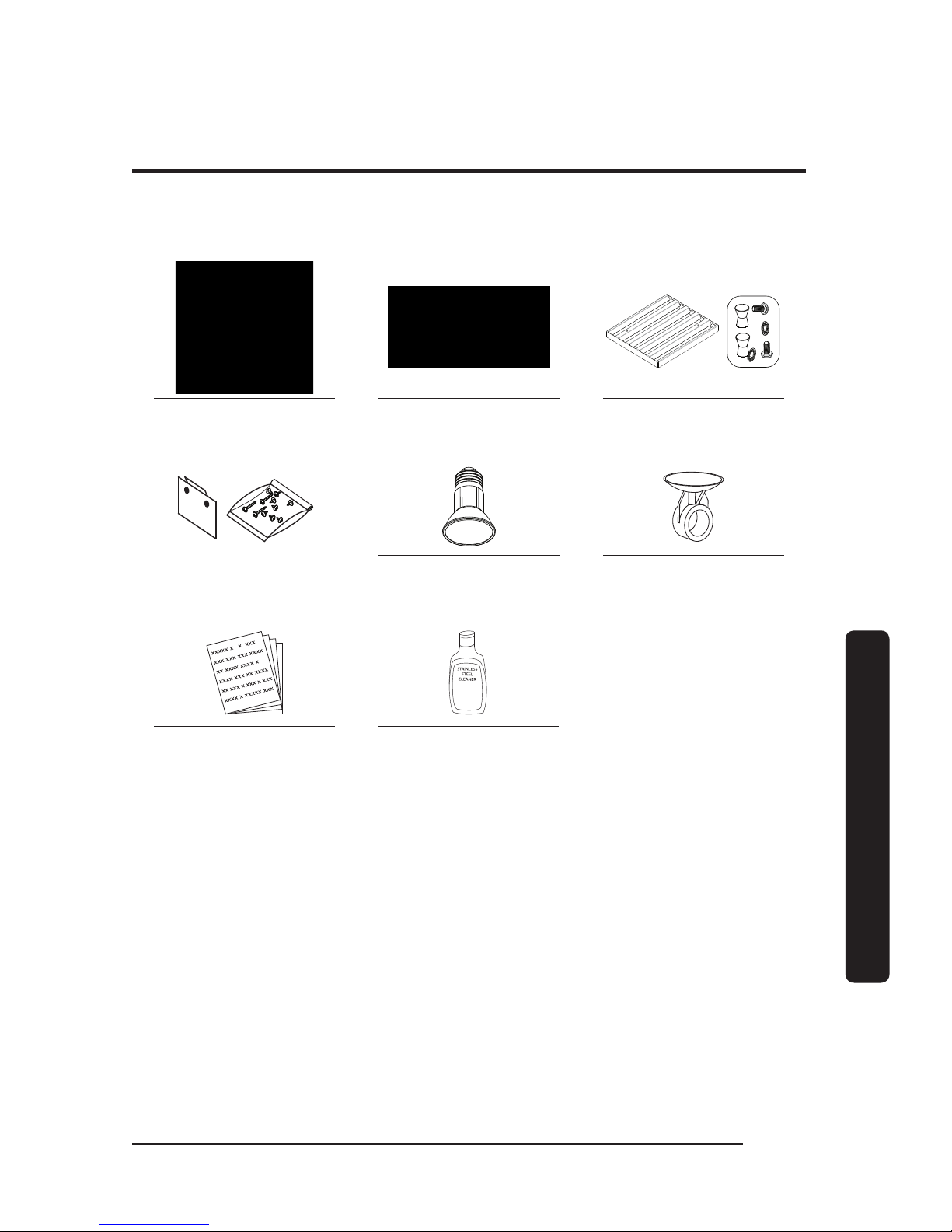
Parts List
Hood (1)
(models vary in size)
Grease channel (1) Baffle-style filter*
48” (4), 36” (3), 30” (2)
Holding brackets, Hardware
(2)
Dimmable LED light bulbs
48” (4), 36” (3), 30” (2)
Light-replacement tool (1)
Product literature** (2)
Dacor cleaning cream (1)
stainless steel units only
* Ready-to-assemble kit
** Installation instruction, User manual.
English12
Installation requirements
Installation requirements
Installation Planning
• A qualified technician must complete the installation of this built-in appliance. Proper
installation is the customer's responsibility.
• Carefully check the location where the Hood is to be installed.
The Hood should be placed for convenient access. Make certain that electrical power
can be provided in the selected location.
• Plan the installation so that all minimum clearances are met or exceeded. Dimensions
shown provide minimum clearances, unless otherwise noted. Be certain that proper
clearance is provided for the Hood when it is in the open position.
• The specified minimum cabinet depth and width must be provided.
• Make certain that you have everything necessary to ensure a proper installation before
proceeding.
Hood Dimension
General Specifications
All Models: DHD30/36/48
Features Description
Blower Speeds Four (4)
Filters Baffle style, dishwasher safe
Exhaust(s) 8” duct diameter
Total Connect Load
30”, 36”: 120V, 60 Hz, 15 Amp (actual load 3.3 Amp, 6
Amp initial surge)
48”: 120V, 60 Hz, 15 Amp (actual load 6.1 Amp, 12 Amp
initial surge)
Lights
Dimmable LED: PAR16 E26/27; 120V, 7.5W (75W Max.
other bulbs)
English 13
Installation requirements
Individual Models: DHD30/36/48
Components 48” 36” 30”
Lights
4 3 2
Filters
Blowers
2 1 1
Exhaust Vents
Blower Rating 1200 CFM 600 CFM 600 CFM
Weight Specifications
Individual Models: DHD30/36/48
Model Weight
30 53 lbs (24 kg)
36 57 lbs (26 kg)
48 77 lbs (35 kg)
Individual Models: DHD30/36/48
Model Top Vent Rear Vent Rotatable Fan
30 x x x
36 x x x
48 x x x
English14
Installation requirements
Installation requirements
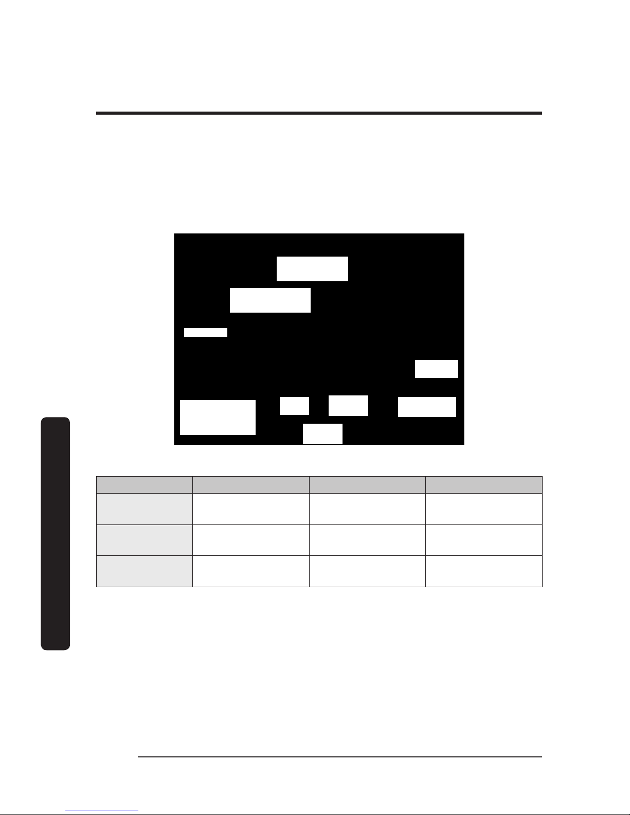
Electrical/Ductwork Connections
Connect electrical wires and ductwork through the top or rear of the hood. Before
installing the hood, mark the access holes according to the diagrams below.
(Tolerances: +1/16” -0”, unless otherwise stated.)
Top Connections: All models
Dual-Exhaust
Standard 8" duct
Single-Exhaust
Standard 8" duct
*See table
5 3/4 in.
(14.6 cm)
Hood back
(against wall)
Hood
C/L
9 7/8 in.
(25.1 cm)
19 3/4 in.
(50.2 cm)
(2) ElectricalAccess Holes
7/8 in. (5.1 cm) dia.
Dimensions: Top Electrical Access Holes (DHD 30/36/48)
Model A B C
48
1 1/2”
(3.81 cm)
5”
(12.7 cm)
3”
(7.62 cm)
36
1 1/2”
(3.81 cm)
4 1/2”
(11.43 cm)
3”
(7.62 cm)
30
1 1/2”
(3.81 cm)
5 1/2”
(13.97 cm)
3”
(7.62 cm)
 Loading...