

CyClone SI530, SC722, SC715, SI523, SI521 Installation And Operation Instructions Manual
...
Self-Cleaning Range Hoods
Wall Mount and Island Range Hoods
Models:
SC(B)500, SC(B)501, SC(B)502, SC(B)503, SC510,
SC(B)513, SC(B)514, SI(B)323, SI(B)520, SI(B)521,
SI(B)522, SI(B)523, SI530, SI531, SI532
SCB711, SC322, SCB722, SC712, SC(B)715,
SCB717, SCB718, SC720, SC(B)722
Installation and Operation Instructions
Please read all instructions before installing and operating.
All wiring and installation must be in accordance with CEC, NEC and local electrical codes.
READ AND SAVE THESE INSTRUCTIONS

2 Cyclone Canopy Installation - English
IMPORTANT SAFETY INSTRUCTIONS
WARNING
• is appliance must be installed by a qualied technician.
• e manufacturer declines all responsibilities in the event of
failure to observe the instructions given here for installation,
maintenance and suitable use of the product.
• e manufacturer further declines all responsibility for injury
due to negligence, and the warranty of the unit automatically
expires due to improper installation and maintenance.
CAUTION
• For indoor use only.
• For general ventilation use only. Do not use to exhaust hazardous
or explosive materials or vapors.
• Two installers are recommended because of the size and
weight of this hood.
WARNING
TO REDUCE THE RISK OF RANGE TOP GREASE FIRE:
1. Never leave the range unattended at high settings.
2. Always turn hood ON when cooking at high heat or when
aming food.
3. Use proper pan size. Always use cookware appropriate for
the size of the surface element.
4. Keep fan, lters and grease laden surfaces clean. Clean
ventilating fans frequently. Do not allow grease to accumulate
on fan or lter.
5. Use HIGH setting on hood only when necessary.
6. Don’t leave hood unattended when cooking.
7. To reduce the risk of re, use only metal ductwork.
8. is unit must be grounded.
9. Not for outdoor use.
WARNING
TO REDUCE THE RISK OF FIRE, ELECTRIC SHOCK, OR
INJURY TO PERSONS, OBSERVE THE FOLLOWING:
1. Use this unit only in the manner intended by the manufacturer.
2. Before servicing or cleaning the unit, switch power o
at service panel and lock service panel to prevent power
from being switched on accidentally. When the service
disconnecting means cannot be locked, securely fasten a
prominent warning device to the service panel.
3. Installation work and electrical wiring must be done by
qualied persons in accordance with all applicable codes
and standards, including re-rated construction.
4. Sucient air is needed for proper combustion and exhausting
of gases through the ue of fuel burning equipment to
prevent back draing. Follow the heating equipment
manufacturer’s guideline and safety standards as published
by the local code authorities.
5. When cutting or drilling into walls or ceilings, be careful
not to damage existing electrical wiring and other hidden
utilities.
6. To reduce the risk of re, electric shock and to properly
exhaust air, ducted fans must always be vented outdoors.
Do not vent exhaust air into spaces within walls, ceilings,
attics, crawl spaces, or garages. Do not connect this fan
with any solid-state speed control device.
7. Always keep the duct clear to maintain proper airow for
venting.
8. e bottom of the hood MUST NOT BE LESS than 28”
and at a suggested maximum of 36” above cooktop for
best capture of cooking impurities. For a gas range, the
bottom of the hood MUST NOT BE LESS than 30” above
cooktop.
WARNING
• Do not repair or replace any part of this appliance unless
specically recommended in this book. All other service
should be performed by a qualied technician.
• e hood motor has a thermal overload that will
automatically shut o the motor if it becomes overheated.
e motor will restart. If the motor continually shuts o
and restarts, contact the Cyclone service department.
Ensure that the hood is mounted at the recommended
mounting height.
• is product may have sharp edges. Be careful to avoid
cuts and abrasions during installation and cleaning.
3Cyclone Canopy Installation - English

CONTENTS
Important Safety Instructions 3
Damage Inspection 5
Ducting 5
Mounting Heights and Clearance 6
Wiring Installation 6
Wall Mount Installation - Tools and Materials Required 7
Wall Mount Installation - Parts Supplied 7
Wall Mount Hood Installation 8
Island Installation - Tools and Materials Required 9
Island Installation - Parts Supplied 9
Island Hood Installation 10
Canopy Hoods Specications 12
Troubleshooting 38
Control Panel 39
Maintenance 39
Cyclone Range Hoods Limited Warranty 40
4 Cyclone Canopy Installation - English
DAMAGE INSPECTION
• Please fully inspect unit for damage before installation.
• If the unit is damaged in shipment, return the unit to the store in which it was bought for repair or replacement.
• If the unit is damaged by the customer, repair or replacement is the responsibility of the customer.
• If the unit is damaged by the installer (if other than the customer), repair of replacement must be made by arrangement between
customer and installer.
• Once installed, all damages will be assumed the responsibility of the installer.
DUCTING
WARNING
• To reduce the risk of re, use only metal ductwork.
• To reduce risk of re and to properly exhaust air, be sure
to duct air outside – do not vent exhaust air into spaces
within walls, ceilings, attics, crawl spaces, or garages.
CAUTION
• Best to use rigid type metal ducts. Flexible ducts can
restrict airow by more than 50%.
• Reduce the number of transitions and turns as much as
possible. If a reducer is used, install a long reducer instead
of a pancake reducer. If turns and transitions are required,
install them as far away from the opening as possible and
as far apart between two as possible.
WARNING
• 6” round ductwork must be used to maintain maximum
air ow eciency with motors of 450 CFM or greater. If
the use of any size ducting is less than 6”, the warranty is
automatically voided.
• e venting duct must go horizontally or vertically up to the
outside wall or the roof. If it is turned downward anywhere
in the venting system, the warranty is automatically voided.
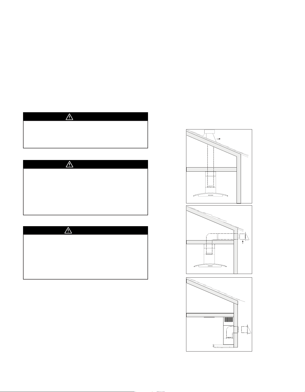
Examples of dierent types of ventilation for island
and wall mounted canopies:
Roof Pitch with Cap
and Flashing
Soffit or crawl space
Side wall cap with
gravity damper
Fasten all connections with sheet metal screws and tape all joints
with certied silver tape or duct.
Do not cut a joist or stud unless absolutely necessary. If a joist or
stud must be cut then a supporting frame must be constructed.
Before making cutouts make sure there is proper clearance within
the ceiling or wall for the exhaust vent.
Additional parts not provided.
Side wall cap with
gravity damper
5Cyclone Canopy Installation - English

MOUNTING HEIGHTS AND CLEARANCE
WARNING
• e hood should be installed at 28” minimum above the
cooking surface. If pairing your range hood with a gas
stove minimum mounting height must be 30” above the
cooking surface.
Minimum mount height between range top to hood bottom should
be no less than 28” for electric or ceramic stoves, and no less than 30”
for gas stoves. e maximum mount height should be no more than
36”. e hood must be installed at the correct mounting height. Hoods
mounted too low could result in heat damage. Hoods mounted too
high, on the other hand, will be less eective and performance may
suer.
Check your ceiling height and the hood height maximum before
you select your hood.
Hood installation height above cook top is the user’s preference.
e lower the hood is above the cook top the more ecient it will
be in drawing out cooking odors, grease and smoke.
Min:
Ceramic/Electric
Gas 30”
36”
Max:
36”
28”
WIRING INSTALLATION
is appliance requires 120V 60Hz electrical supply and connection to an individual properly grounded branch circuit protected
by a circuit breaker or time delay fuse.
Grounding Instructions
is appliance must be grounded.
is appliance is equipped with a cord having a grounding wire or
with a plug having grounding wire. e grounding wire must be
grounded properly in the junction box or the plug must be plugged
into an outlet that is properly installed and grounded.
1. Connect the power line ground wire to the green ground wire
supplied with the hood.
2. Connect the black power wire to the black wire supplied with
the hood.
3. Connect the white neutral wire to the white wire supplied with
the hood.
Black: Power
White: Neutral
Install the Electrical Power Supply
Position the outlet or junction box within the space covered by the
duct cover. Place the outlet or junction box at a maximum distance
of 24” from where the cord exits from the hood. e center of
the outlet or junction box should be positioned at 2 ¾” away from
the center of the future hood location. Make sure this does not
interfere with the mounting area or with the duct cover.
Max. 2 ¾”
Min: 3”
6 Cyclone Canopy Installation - English
Green: Ground
PLEASE REFER TO PAGES 13-37 FOR YOUR MODEL’S SPECIFICATIONS
WALL MOUNT INSTALLATION - TOOLS AND MATERIALS REQUIRED
• Electrical drill or ratchet driver
• ½” drill bit for drilling pilot holes
• 1 ¼” drill bit for drilling electrical wiring access
hole (if applicable)
• Phillips screwdriver #2 or driver bit
• Wire stripper or cutter
• Tape measure
• Aluminum foil tape and/or duct tape
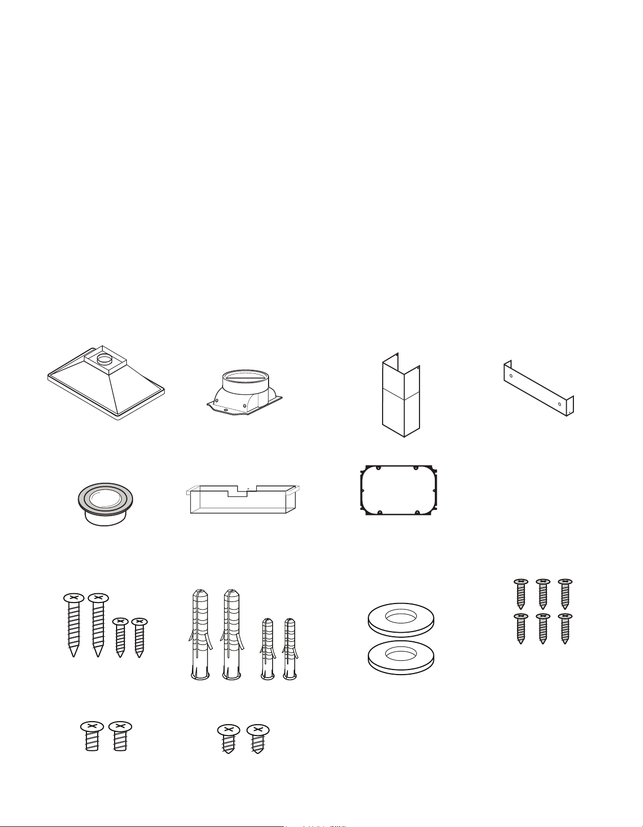
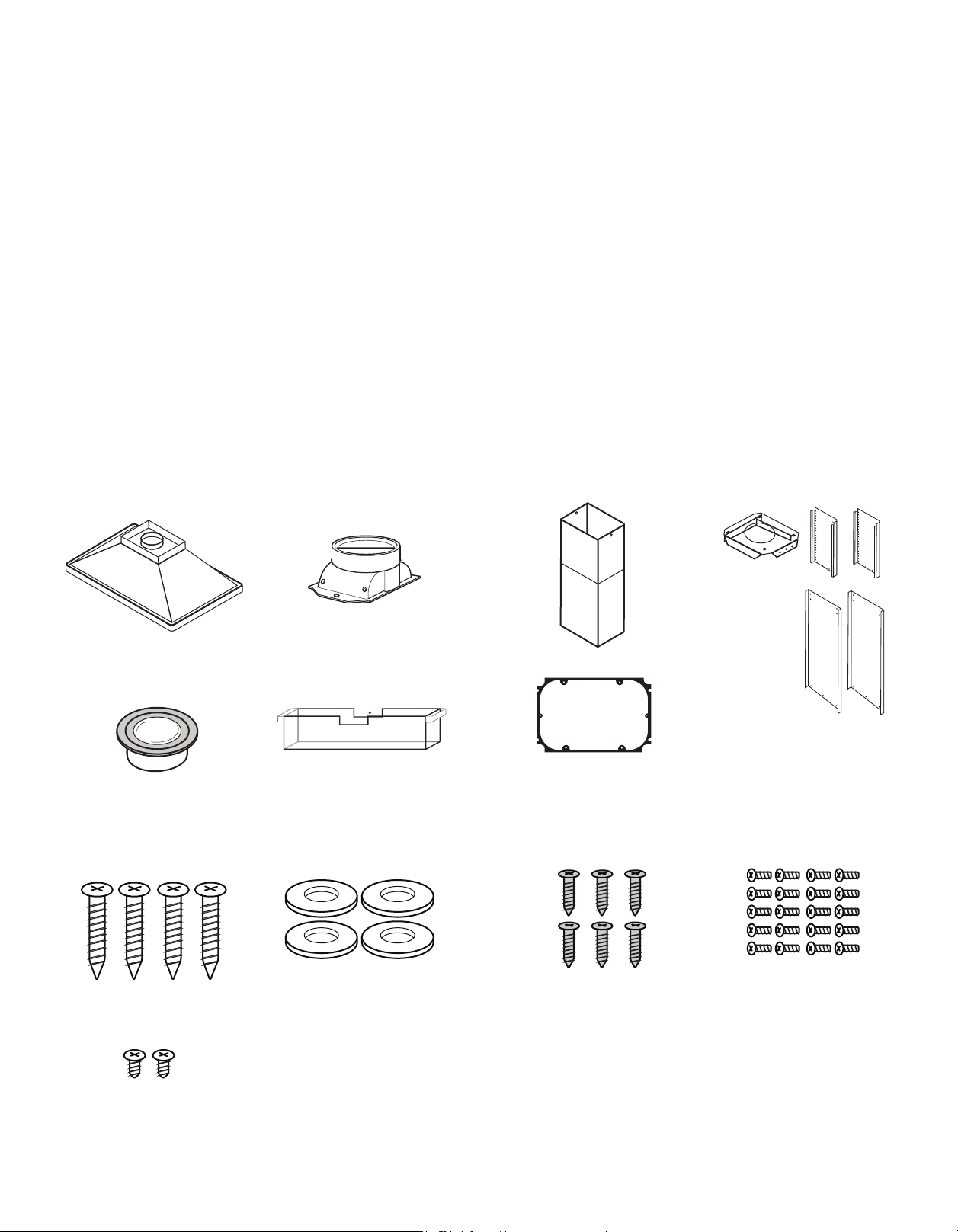
WALL MOUNT INSTALLATION - PARTS SUPPLIED
1 × Hood
1 × Round Adapter
(May be Pre-Installed)
• Electrical supplies for wiring (i.e. marrets,
electrical tape)
• Hammer
• Jigsaw or saber saw
• Drywall stud (if applicable)
• Step ladder
• Stud nder
• Level
1 × Chimney Flues
(Top and Bottom)
1 × Upper Mounting Bracket
PRE-INSTALLED
2 or 4 × G4 Type JC Lights
(12V, 20W)
1 × Oil Cup
HARDWARE PACKAGE
4 × Mounting Screws
(Long and Medium, 2 each)
2 × Top Chimney Screws SC500, SC711, SC715 ONLY:
4 × Drywall Anchors
(Large and Small, 2 each)
2 × Bottom Chimney Screws
1 × Plastic Adapter Seal
2 × Washers
6 × Adapter Screws
7Cyclone Canopy Installation - English
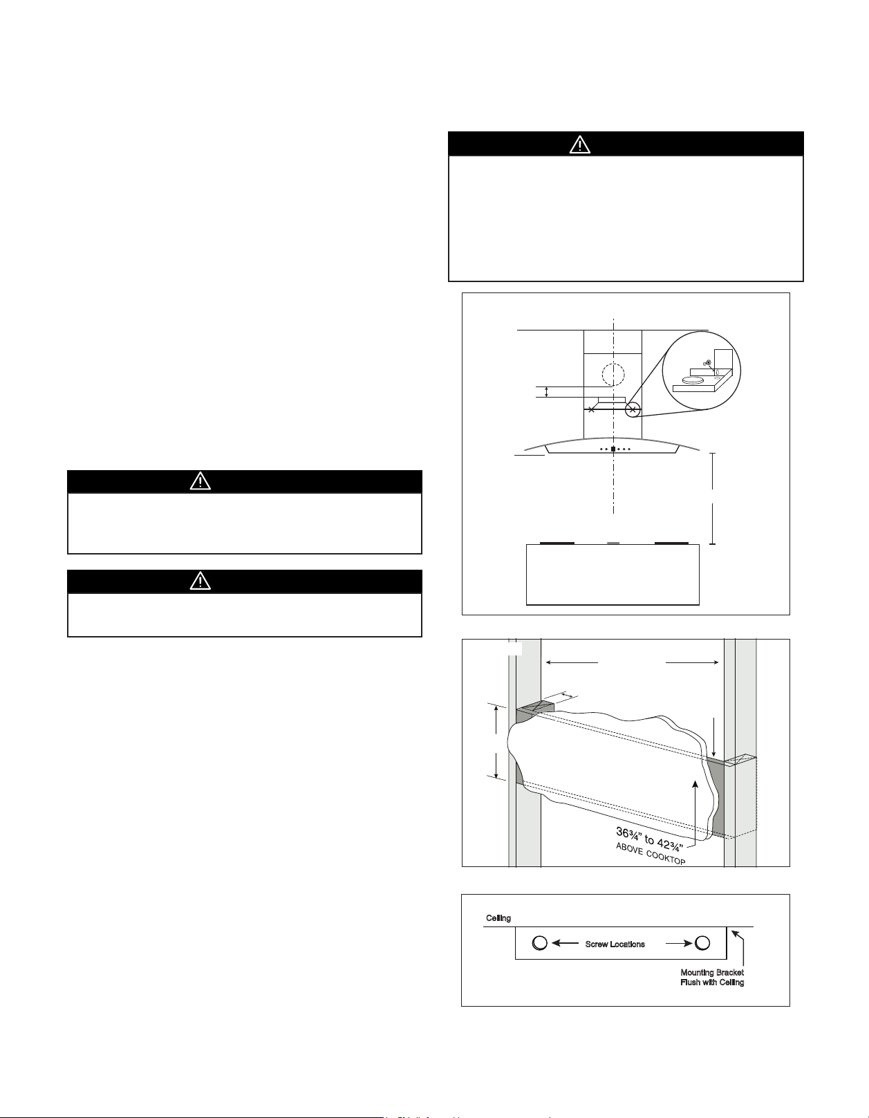
WALL MOUNT HOOD INSTALLATION
Install the Wall Mount Hood
1. Measure from range top to hood bottom and use a leveler
to mark line A (28” minimum from range top for electric/
ceramic stoves, 30” minimum from range top for gas stoves).
2. Place and mark center line C/L.
3. Use the hood fan as template to nd the mounting screws
position. Keep the hood bottom centered and level on line
A. Mark the position of the two mounting screws (Figure 1).
Important: e minimum allowable distance from the top of the
damper on range hood to the bottom of the ductwork protruding
from wall is 3”.
4. Fasten two mounting screws into studs where possible at the
positions marked with an X. Do not fasten screws all the way.
5. Where studs are not available, you must construct wood wall
framing that is ush with surface of wall studs. Wood wall
framing should be at least 1/2” thick and 3” high. Assemble
wood wall framing to wall studs for a secure installation.
Make sure the height of the framing allows the hood fan to be
secured to the wood block (Figure 2).
CAUTION
• Wood blocking may need to be added behind the drywall
if no studs are present. Wall anchors may also be used,
check local codes before using wall anchors.
CAUTION
• At least two installers are required due to the weight and
size of the hood.
• Turn o power circuit at the service panel before wiring
this unit.
• All electrical work must be done by a qualied electrician
in accordance with all applicable codes and standards.
is range hood must be properly grounded.
Figure 1.
Min. 3”
A
C/L
Min. 28-30”
WARNING
• When cutting or drilling into wall, do not damage electrical
wiring and other hidden utilities.
6. Center the upper cover mounting bracket with the center line
and mount it ush with the ceiling by drilling pilot holes and
using small anchors provided (Figure 3).
7. Install 6” round adapter if not preinstalled.
8. Remove the lters from the hood.
9. Hang hood onto screws and hand tighten. If possible, use
extra screws to further secure the hood to the wall from inside
the hood.
10. Install 6” round duct over the adapter, connect it with the
venting duct coming from the wall or ceiling. Use metal foil
duct tape to seal the joint.
11. Install electrical connection. Turn on the hood and check for
leaks around duct tape.
12. Place telescopic duct covers onto hood and extend inner top
duct cover upwards and secure to duct cover bracket.
13. Reinstall lters to the hood. Remove protective plastic lm
covering the duct covers and hood.
Figure 2.
Min. 3”
Figure 3.
Ceiling
Wall Studs
Min. 1 ½”
Screw Locations
Framing Behind
Drywall
Mounting Bracket
Flush with Ceiling
8 Cyclone Canopy Installation - English
PLEASE REFER TO PAGES 13-37 FOR YOUR MODEL’S SPECIFICATIONS
ISLAND INSTALLATION - TOOLS AND MATERIALS REQUIRED
• Electrical drill or ratchet driver
• ½” drill bit for drilling pilot holes
• 1 ¼” drill bit for drilling electrical wiring access
hole (if applicable)
• Phillips screwdriver #2 or driver bit
• Wire stripper or cutter
• Tape measure
• Aluminum foil tape and/or duct tape
ISLAND INSTALLATION - PARTS SUPPLIED
1 × Hood
1 × Round Adapter
(May be Pre-Installed)
• Electrical supplies for wiring (i.e. marrets,
electrical tape)
• Hammer
• Jigsaw or saber saw
• Drywall stud (if applicable)
• Step ladder
• Stud nder
• Level
1 × Chimney Flues
(Top and Bottom)
3 × Mounting Brackets
(Upper and Expandable Side)
PRE-INSTALLED
2 or 4 × G4 Type JC Lights
(12V, 20W)
4 × Mounting Screws
SI520 ONLY
2 × Bottom Chimney Screws
1 × Oil Cup
1 × Plastic Adapter Seal
HARDWARE PACKAGE
4 × Washers
6 × Adapter Screws
20 × Mounting Bracket Screws
9Cyclone Canopy Installation - English
4 ⅜”
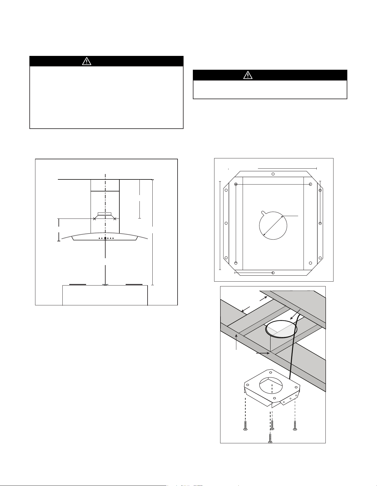
ISLAND HOOD INSTALLATION
CAUTION
• At least two installers are required due to the weight and
size of the hood.
• is hood should be installed to a nished ceiling.
• Turn o power circuit at the service panel before wiring
this unit.
• All electrical work must be done by a qualied electrician
in accordance with all applicable codes and standards.
is range hood must be properly grounded.
Measure Installation Height
C/L
D
Blower Top Box
B
C
Install Mounting Bracket
WARNING
• When building framework, always follow all applicable
construction codes and standards.
1. Modify ceiling structure at hood location. Install 2 × 4
cross framing between ceiling joists using ceiling mounting
bracket dimension (Figure 4). e framework must be sized
to support the total weight of the hood.
2. Finish ceiling surface. Be sure to mark the location of the
ceiling joists and cross framing. Bring house wiring through
nished ceiling.
Figure 4.
11 ¼”
9 ⅝”
10 ½”
8 ¾”
1 ⅜”
3 ⅜”
ø 6 ¾”
Range Hood Bottom
A
Determine the required distance between the ceiling and the top of
the blower box (D) based upon ceiling height (C), desired height of
hood above cooktop (A) and unit height (B):
D=C-A-B
e height D is the installation height of the mounting bracket
(Figure 3) . If the installation height D is less than 22”, the mounting
bracket and duct covers may need to be cut. e duct cover needs a
clean cut and must to be cut from bottom end sides for both inside
and outside pieces. For optimal clearance, the minimum mounting
should be 30” above the cooking surface.
Figure 5.
Ceiling Joists
Cross Framing
Upper Mounting
Bracket
6” Round
Ductwork
10 Cyclone Canopy Installation - English
3. Position the ceiling mounting plate in such a way that one of
the sides with three screw holes faces the front of the hood.
Secure mounting bracket to the ceiling using four wood
screws. Ensure that screws are driven into the center of the
framing for maximum strength. Assemble two upper side
brackets to the ceiling mounting bracket using six mounting
screws (three per bracket) (Figure 5 & 6).
4. Use eight screws to mount the lower brackets to the upper
brackets. Determine lower brackets mounting height based
upon installation height D of the mounting bracket.
Note: 10 Feet Ceilings
For SI520, use the mounting brackets and duct covers supplied.
For any other models, optional extension mounting brackets
and duct covers need to be ordered.
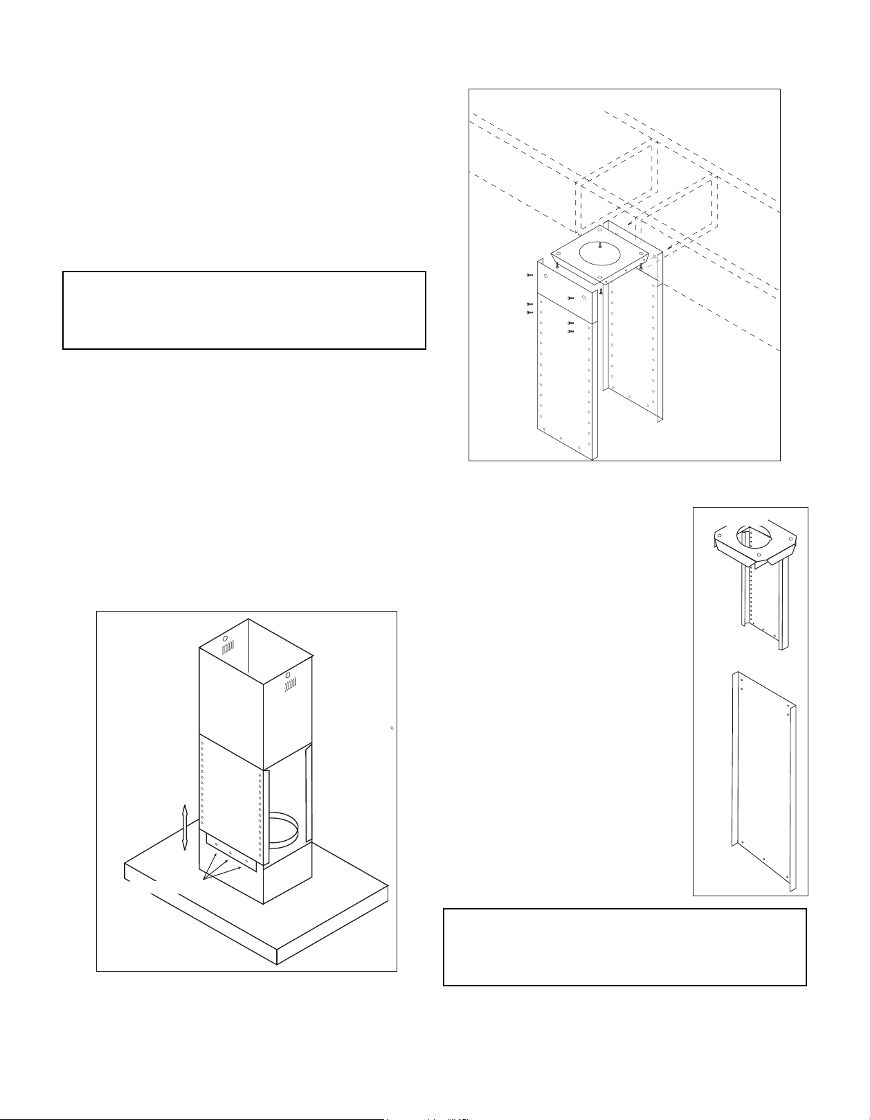
Install the Island Hood
Figure 6.
1. Remove the lters from the hood; attach the adapter/damper
to the top of the hood.
2. Measure the required length of 6” round metal duct from the
adapter/damper to the ductwork rough-in in the ceiling.
Connect this section of duct to the adapter/damper and seal
joint with metal foil duct tape.
Figure 7.
Mounting Screws
3. Slide the lower and upper chimney ues
over the installed mounting bracket
and have a second person hold it to the
ceiling.
4. Attach the hood to mounting bracket using
six screws (three per side) (Figure 7).
5. Slide the lower and upper chimney ues
down on top of the hood. Install the
electrical connection and connect the
duct to the rough-in duct work in the
ceiling. Seal the joints with metal foil
duct tape.
6. Power up hood and check for leaks
around duct tape.
7. Carefully slide the upper (inner) ue
over up to the ceiling and secure it to the
mounting plate from both sides.
8. Reinstall lters to the hood, peel o the
protective plastic lm covering the ues
and the hood.
Figure 8.
Note: For some models, the “L” shape support frame may be
used (Figure 8). e installation procedures are same except
that the hood is mounted on one side. If need be, use an
adjustable string wire from other side to keep the hood level.
11Cyclone Canopy Installation - English
CANOPY HOODS SPECIFICATIONS
W
SIZE
MOUNTING
MAX.
CUBIC FEET/METER
(CFM)
MAX. SONES
FINISH
CONTROLS
SPEED LEVELS
SC300/SC301/SC322/
SI323
30”/36”
WALL
SI323 - ISLAND
SC500/SC501/SC502/
SC503/SC510/SC513/
SC514
30”/36”
SC500/SC514 - 24”/30”/36”
WALL WALL WALL ISLAND
SC707/SC712/SC717/
SC718/SC720/SC722/
SC727/SC771
30”/36”
SC718 - 36”
SCB500/SCB501/
SCB514/SC711/SC715
30”/36”
SCB500/SCB514 -
24”/30”/36”
SI520/SI521/SI522/
SI523/SI530/SI531
36”
SI523 - 30”/36”
300 550 650 650 600
2.5 6 6 6 6
STAINLESS STEEL
STAINLESS STEEL + GLASS
STAINLESS STEEL
STAINLESS STEEL + GLASS
STAINLESS STEEL
STAINLESS STEEL + GLASS
STAINLESS STEEL
STAINLESS STEEL + GLASS
STAINLESS STEEL
STAINLESS STEEL + GLASS
PUSH BUTTON PUSH BUTTON PUSH BUTTON PUSH BUTTON PUSH BUTTON
3 3 3 3 3
DELAY OFF
LIGHTING
FILTERS
EXTENSION DUCT
OPTION
DUCT
AC INPUT
POWER
CONSUMPTION
MOUNTING HEIGHT
YES YES YES YES YES
2 × 12V 20W
HALOGEN
SI323 - 4 × 12V 20W
2 × 12V 20W
HALOGEN
2 × 12V 20W
HALOGEN
2 × 12V 20W
HALOGEN
2 × 12V 20W
HALOGEN
SI523 - 4 × 12V 20W
ALUMINUM MESH ALUMINUM MESH ALUMINUM MESH BAFFLE ALUMINUM MESH
YES, 10’ + CEILING
SPECIAL ORDER
YES, 10’ + CEILING
SPECIAL ORDER
YES, 10’ + CEILING
SPECIAL ORDER
YES, 10’ + CEILING
SPECIAL ORDER
YES, 10’ + CEILING
SPECIAL ORDER
6” ROUND TOP 6” ROUND TOP 6” ROUND TOP 6” ROUND TOP 6” ROUND TOP
120V
60Hz
120V
60Hz
120V
60Hz
120V
60Hz
120V
60Hz
180W 200W 200W 200W 200W
28”-36” 28”-36” 28”-36” 28”-36” 28”-36”
12 Cyclone Canopy Installation - English
 Loading...