

CyClone NA-930, NA-930R, CY-1000, CY-1000R Installation And Operating Instructions Manual
Self-Cleaning Range Hoods
Hottes Autonettoyantes
(Model/Modèle NA-930/R)
(Model/Modèle CY-1000/R)
Installation and Operating Instructions
Instructions d’installation et d’opération
Please read all instructions before installing and operating.
Veuillez lire toutes les instructions avant l'installation et l'opération.
All wiring must be in accordance with national and local electrical codes.
Tous les câblages doivent être conformés aux codes électriques
nationaux et locaux.

IMPORTANT SAFETY INSTRUCTIONS
READ AND SAVE ALL INSTRUCTIONS BEFORE INSTALLING OR OPERATING YOUR
CYCLONE RANGE HOOD
1. Cyclone range hood is for general purpose ventilating use only. Do not use it to exhaust hazardous,
explosive materials or vapors.
2. The safety mesh that covers the inlets to the fan must be cleaned periodically to prevent excess
grease buildup. Make sure the mesh is installed before operating the fan.
3. Do not use more than 60W incandescent light bulbs for any model. Do not use round shaped light
bulb for models CY1000 or CY1000R. Recommended use of tubular light bulb (T10) or 23W
florescent tube (equivalent to a 90W incandescent light bulb).
4. Ensure the power is turned off before installation or maintenance. If you move the range hood to
make room for working on the cabinet, turn off the 220V power for an electric range at the service
entrance. Before moving a gas range, shut off the gas.
5. When cutting or drilling into walls or ceilings, be careful not to damage existing electrical wiring and
other hidden utilities. Use only metal ductwork.
6. All electrical connections must be in accordance with local codes, ordinances, or National Electrical
Code. If you are unfamiliar with methods of installing electrical wiring, secure the services of a
qualified electrician.
7. When installed, the bottom edge of your Range Hood should be 24” – 32” above the top of cooking
surface.
8. Always keep the duct clear to maintain proper airflow for venting.
9. To reduce the risk of fire, electric shock and to properly exhaust air, ducted fans must always be
vented outside. Do not vent exhaust air into spaces within walls, ceilings, attics, crawl spaces or
garages. Do not connect this fan with any solid-state speed control device.
10. To reduce the risk of a range top grease fire, always have the fans turned on when cooking at high
heat or when cooking flaming foods. Do not leave your range unattended when cooking at high
setting. Always keep the range hood clean. Grease should not be allowed to accumulate on fans or
hood.
TOOLS AND MATERIALS REQUIRED
• Electrical drill or Ratchet Driver
• ½” drill bit for drilling pilot holes
• 1 ¼” drill bit for drilling electrical wiring access
hole
• Screwdrivers: philips & straight blade
• Pliers
• Tape measure or ruler and pencil
• Electrical supplies for wiring
• Aluminum foil tape and/or duct tape
• Hammer
• Jigsaw or saber saw
• 6 tapping screws (supplied)
• 4 hood mount screws (supplied)
• 2 rectangular oil collectors (supplied)
• 2 round shape oil collectors (supplied)
• 1 rectangular damper (supplied only with
rectangular venting models)
2
PREPARATION FOR INSTALLATION
1. Unpack range hood and check contents.
Note: Be cautious of sharp edges within the unit.
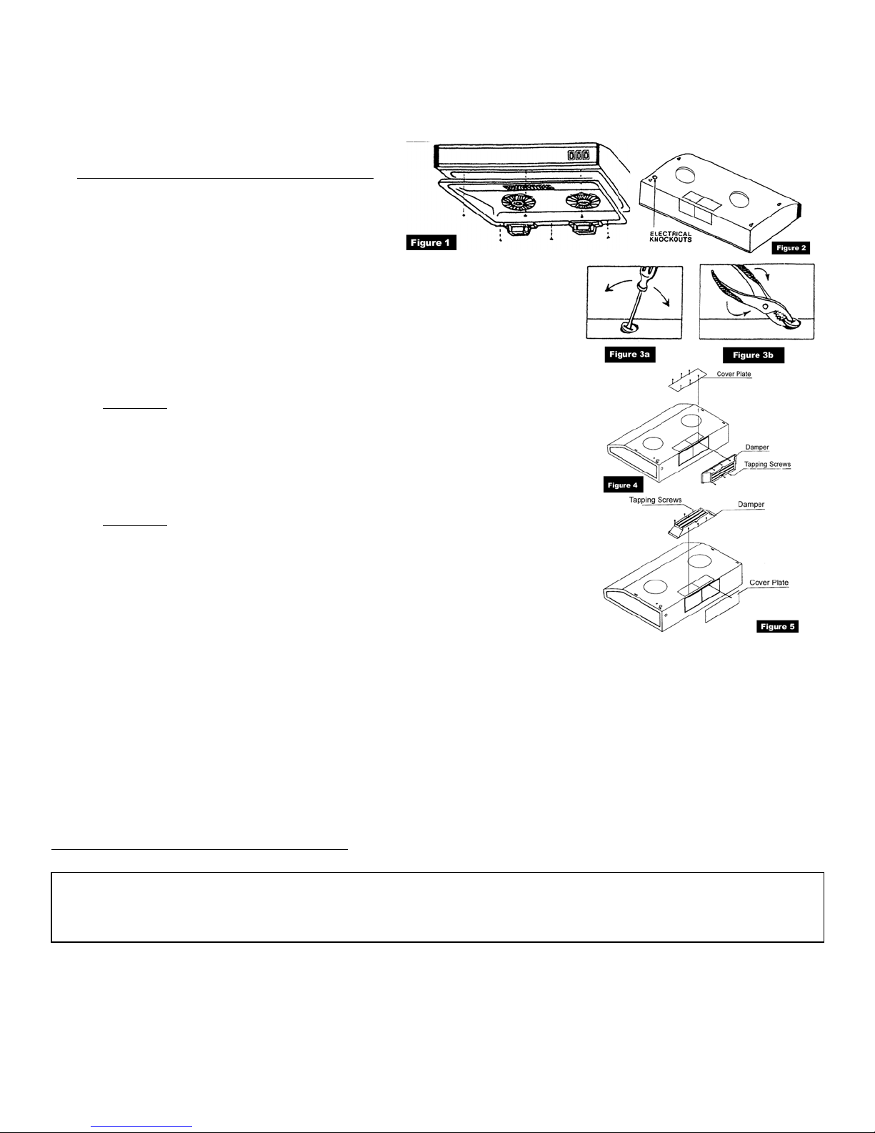
2. Remove hood cover insert screws and lift off cover
to expose the inside (Fig 1).
3. Remove either the top or rear electrical knockout,
depending on how you plan to run power leads to
the hood through cabinet or wall (Fig 2).
4. Insert a screwdriver into the knockout slot and bend the knockout back and
forth (Fig 3a & 3b). You may have to use pliers to pull out the loosened
knockout.
5. For rectangular rear venting configuration (Fig 4):
• Cover the rectangular top cutout with the rectangular cover plate and fasten
with tapping screws.
• Place the rectangular damper onto the rear cutout and fasten with tapping
screws.
• Important:
tape (preferred) or duct tape.
6. For rectangular top venting configuration (Fig 5):
• Cover the rear cutout with the rectangular cover plate and fasten with
tapping screws.
• Place the rectangular damper onto the top rectangular cutout and fasten
with tapping screws.
• Important:
tape (preferred) or duct tape.
7. For round top venting configuration: no rear cover or damper required.
Seal both the top cover plate and damper with aluminum foil
Seal both the rear cover plate and damper with aluminum foil
PREPARATION FOR VENT AND EXHAUST DUCT CONNECTION
8. To connect a rectangular vent to a round exhaust duct (or vice versa), use connecting duct.
9. The round vent of Cyclone range hoods is 6” in diameter. If your round exhaust duct is not 6” in diameter, you will need a
connecting duct to accommodate the different sizes. If your exhaust duct is less than 6” in diameter, the efficiency of your
Cyclone range hood will be reduced.
10. If you are connecting a rectangular vent to an existing rectangular duct, you do not need any connecting duct. However, to
install the range hood properly, you should consult/hire a professional.
11. If you do not have an existing exhaust duct going outside your home, you need to make one. Please consult/hire a
professional to do the work properly. In general, for rear venting, you need to cut a rectangular hole on the wall to fit the
rectangular exhaust duct extended to the outside wall. For top venting, cut a rectangular or a 6” round hole through ceiling
or the bottom of cabinet to fit the duct connection.
INSTALLATION PROCEDURES
Preparing Mounting Frame and Location
Ensure the power is turned off before installation or maintenance. If you move the range to make
room for working on the cabinet, turn off the 220V power for an electric range at the service entrance.
Before moving a gas range, shut off the gas.
1. For installation on a recessed bottom cabinet, do steps a. to d. first (Omit these steps if the hood is to be mounted on a
cabinet with a flush bottom):
a. Measure the space (under cabinet) between the inside front edge and inside back edge (Fig. 6). With a saber saw, cut
two 1” x 2” wood filler strips to fill in the bottom of the cabinet.
3
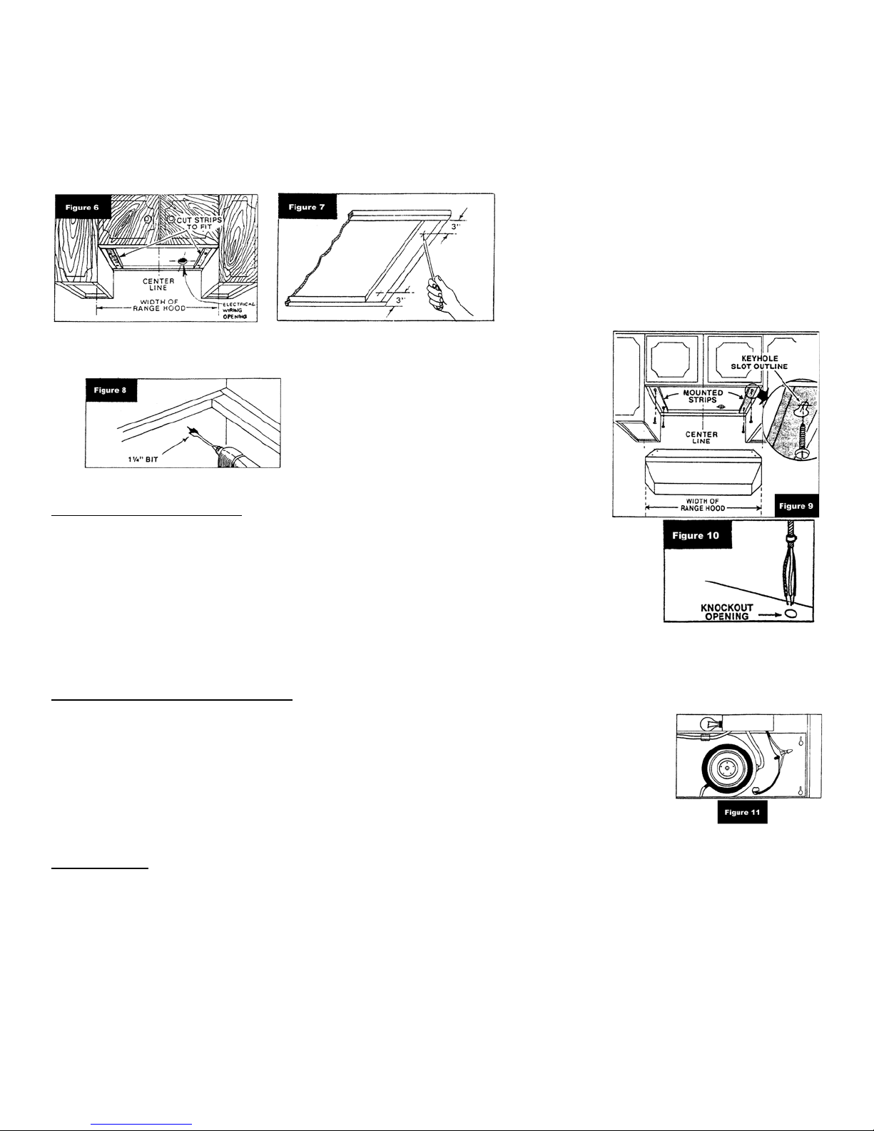
b. Start a 2 ¼” long wood screw about 3” from each end of the 1” x 2” wood strips (Fig. 7). For metal cabinet, drill ½”
holes for the 1” x 2” wood strips and the cabinet at the respective locations.
c. Position the strips on the cabinet bottom and screw the strips securely to the cabinet (Fig. 6).
d. For a more secure installation, drill four 3/16” holes from inside the cabinet, down into the wood filler strips. Insert
screws into the starter holes in cabinet and tighten screws until wood filler strips are secured under cabinet.
2. Center the hood in place beneath the cabinet
and flush with the front of the cabinet.
3. Mark the four keyhole mounting slots for the
hood. Mark these onto the bottom of the
cabinet; or, if the cabinet bottom is recessed,
onto the wood strips.
4. Mark on the cabinet bottom or wall the
5. Drill out the electrical power line
access hole as marked with a 1 ¼”
wood drill bit (Fig. 8).
6. Screw the four hood mounting wood
screws into the center of the keyholes
(Fig. 9) marked on the cabinet bottom
(for flush installation) or the 1” x 2”
wood strips (for recessed cabinet
installation). Do not turn the mounting
screws in all the way to allow
adequate space for the hood to be
fitted into place.
position of the access hole through which the
power supply cord is to be routed.
Providing Electrical Power
7. Place the range hood on the bottom of the cabinet. Route the power supply cord through the
access hole and through the knockout. This step will have to be accomplished while
positioning the hood (Fig. 10).
8. Fit the four wider ends of the keyholes into the four screws on the cabinet, and then adjust
the hood until the screws are pushed into the narrow part of the keyhole slots. The front of
the hood should be flush with the cabinet front.
9. Check to ensure the rear or top vent is fitted and connected to the duct properly.
10. Tighten the hood mounting screws all the way into the cabinet or into the 1” x 2” wood strips
so the hood is firmly attached.
Making the Electrical Connection
11. Secure the electrical connector to the hood with the connector’s “STAR” locknut.
12. Strip about ½” of insulation from the ends of the electrical power wires.
13. Connect the power line ground wire to the green ground wire supplied with the hood (Fig. 11)
14. Connect the black power wire to the black wire supplied with the hood. Do the same with white
wire.
15. Reinstall the hood cover plate with the insert screws.
16. Attach the rectangular and round oil collectors at the far back and under the mesh
respectively.
Use and Care
17. Light bulb: Slide light bulb access cover to expose the lamp-holder. Screw in a light bulb. Do not use round shape light
bulb for models CY1000 or CY1000R. Do not use more than 60W incandescent light for any model. Recommended use
of 23W florescent tube which is equivalent to a 90 W incandescent light bulb.
18. Switches: The fan and light are each controlled by a rocker switch. The light switch has two positions, “ON” and “OFF”.
The fan switch has three positions, “HIGH”, “LOW” and “OFF”.
19. Cleaning: Clean the hood with a mild detergent suitable for painted surfaces. Do not use abrasive cloth, steel wool pads,
or scouring powders.
20. Fan: The fan assembly is designed such that it will never need lubrication.
4
 Loading...