

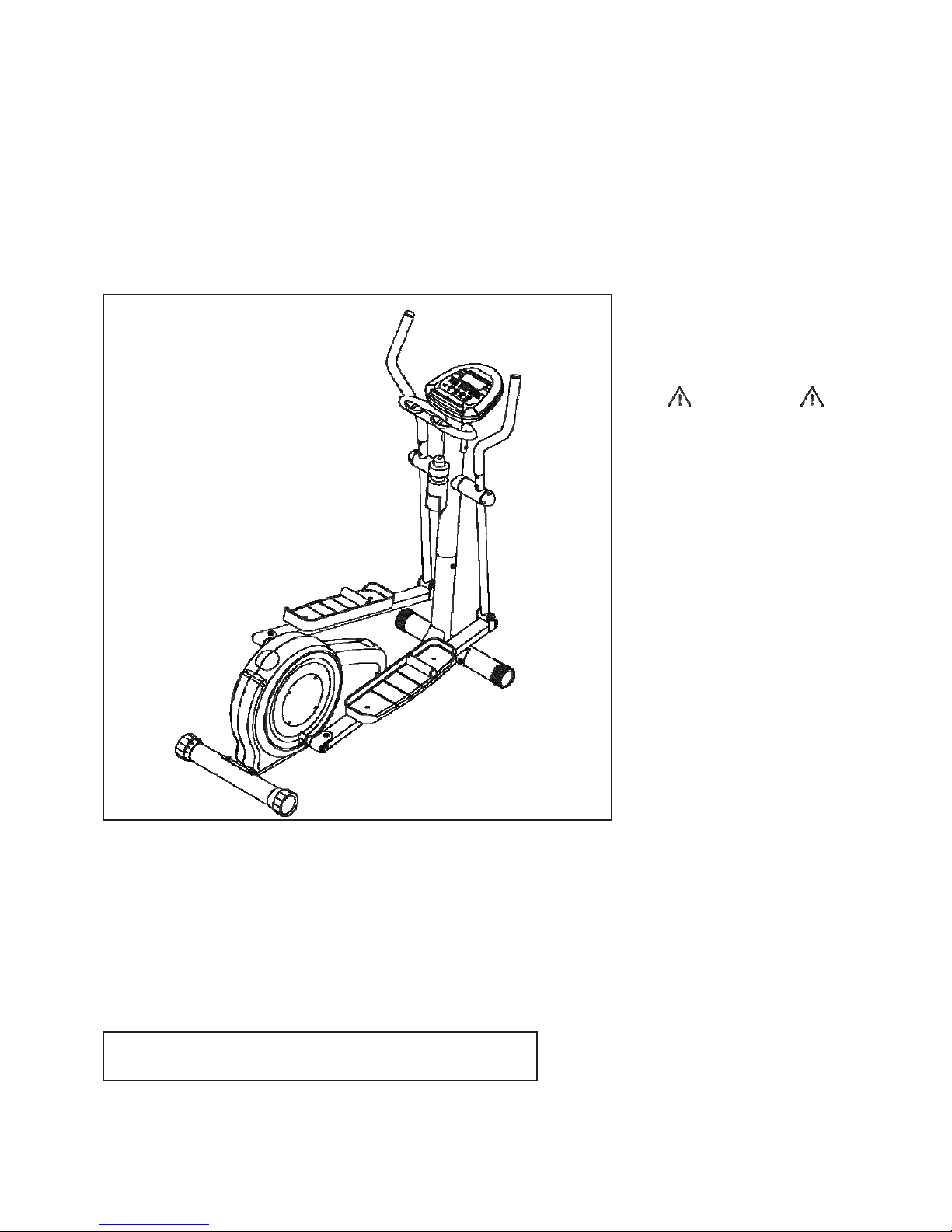
CyClone Elliptical Trainer Owner's Manual
Owner's Manual
WARNING
CAUTION:
Weight on this product should not exceed 250 lbs.
MADE IN TAIWAN
Product May Vary Slightly
From Pictured.
Exercise can present a
health risk. Consult a
physician before beginning
any exercise program with
this equipment. If you feel
faint or dizzy, immediately
discontinue use of this
equipment. Serious bodily
injury can occur if this
equipment is not assembled
and used correctly. Serious
bodily injury can also occur if
all instructions are not
followed. Keep others and
pets away from equipment
when in use. Always make
sure all bolts and nuts are
tightened prior to each use.
Follow all safety instructions
in this manual.

TABLE OF CONTENTS
Page Page
Safety Instructions 2
Hardware Illustrations 3
Assembly Instructions 4
Exercise Workout 8
Storage 8
Maintenance 8
Computer Instructions 9
Conditioning Guidelines 18
Warm-up and Cool-Down 19
Product Parts Drawing 20
Parts List 21
SAFETY INSTRUCTIONS
WARNING: To reduce the risk of serious injury, read the following Safety Instructions before
using th
e ELLIPTICAL.
1.
2.
3.
4.
5.
6.
7.
8.
9.
10.
11.
12.
13.
14.
15.
16.
17.
Read all warnings posted on the ELLIPTICAL.
Read this Owner's Ma nual a nd f ollow it carefully before using the ELLIPTICAL. Make sure that it is
properly assembled and tightened before use.
Keep children away from the ELLIPTICAL. Do not allow children to use or play on the ELLIPTICAL.
Keep children and pets a way from the ELLIPTICAL when it is in use.
Set up and operate the ELLIPTICAL on a solid level surface. Do not position the ELLIPTICAL on
loose rugs or uneven surfaces.
Inspect the ELLIPTICAL for worn or loose components prior to use.
Tighten/replace any loose or worn components prior to using the ELLIPTICAL.
Consult a physician prior to commencing an exercise program . If, at any time during exercise, you
feel faint, dizzy, or experience pain, stop and consult your physician.
Follow your physician's recommendations in developing your own personal fitness program.
Consult your physician before using any of the Heart Programs (P9 to P12). See COMPUTER
INSTRUCTIONS for a description of these programs.
Always choose the workout which best fits your physical strength and flexibility level. Know your
limits and train within them. Always use common sense when exercising.
Do not wear loose or dangling clothing while using the ELLIPTICAL.
Never exercise in bare feet or socks; always wear correct footwear, such as running, walking, or
cross-training shoes. Be sure that they fit well, provide foot support and feature non-skid
rubber soles.
Be careful to maintain your balance while using, mounting, dismounting, or
assembling the
ELLIPTICAL, loss of balance may re sult in a fall and serious bodily injury.
Keep both feet firmly and securely on the Foot Pedals while exercising.
The ELLIPTICAL should not be used by persons weighing over 250 pounds.
The ELLIPTICAL should be used by only one person at a time.
The ELLIPTICAL is for consumer use only. It is not for use in public or semipublic facilities.
WARNING: Before starting a ny exercise or conditioning program you should consult with your personal
physicia n to see if you require a complete physical exam. This is especially i mportant if you
are over the age of 35, have never exercised before, are pregnant, or suffer from any
illness. READ AND FOLLOW THE SAFETY PRECAUTIONS. FAILURE TO FOLLOW
THESE INSTRUCTIONS CAN RESULT IN SERIOUS BODILY INJURY.
2
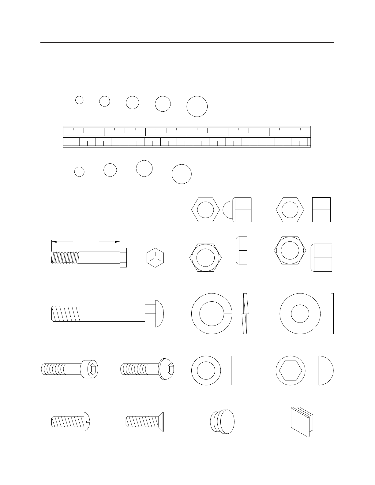
HARDWARE ILLUSTRATIONS
This chart is provided to help identify some of the small parts used in the assembly of this product. This
sheet may not include all the hardware needed to assemble your product. It is intended to be used as a
guide to help simplify your assembly process.
3/16" 1/4" 5/16" 3/8" 1/2"
INCHES
0 1/2 1 1/2 2 1/2 3 1/2 4 1/2 5 1/2 6
in.
0 10 20 30 40 50 60 70 80 90 100 110 120 130 140
150
mm.
MILLIMETERS
6 8 10 12
Place washers, the end of bolts or screws on the
circles to check for the corre ct size. Use the small
scale to check the sizes of bolts and screws.
Length
Acorn Nut Standard Nut
Hex Head Bolt
Thin Nylock Nut Nylock Nut
Carriage Bolt
Socket Head Screw Button Head Screw
Lock Wa sher
Spacer
Flat Washer
Nut Cap
Round Head Screw Flat Head Screw
Round Plug Square Plug
3
ASSEMBLY INSTRUCTIONS
Place all parts from the box in a cleared area and position them on the floor in front of you. Remove all
packing materi als from your area a nd pla ce them ba ck into the box. Do not dispose of the packing materi als
until assembly is completed. Read each ste p carefully before beginning.
LEFT
R
RIGHT
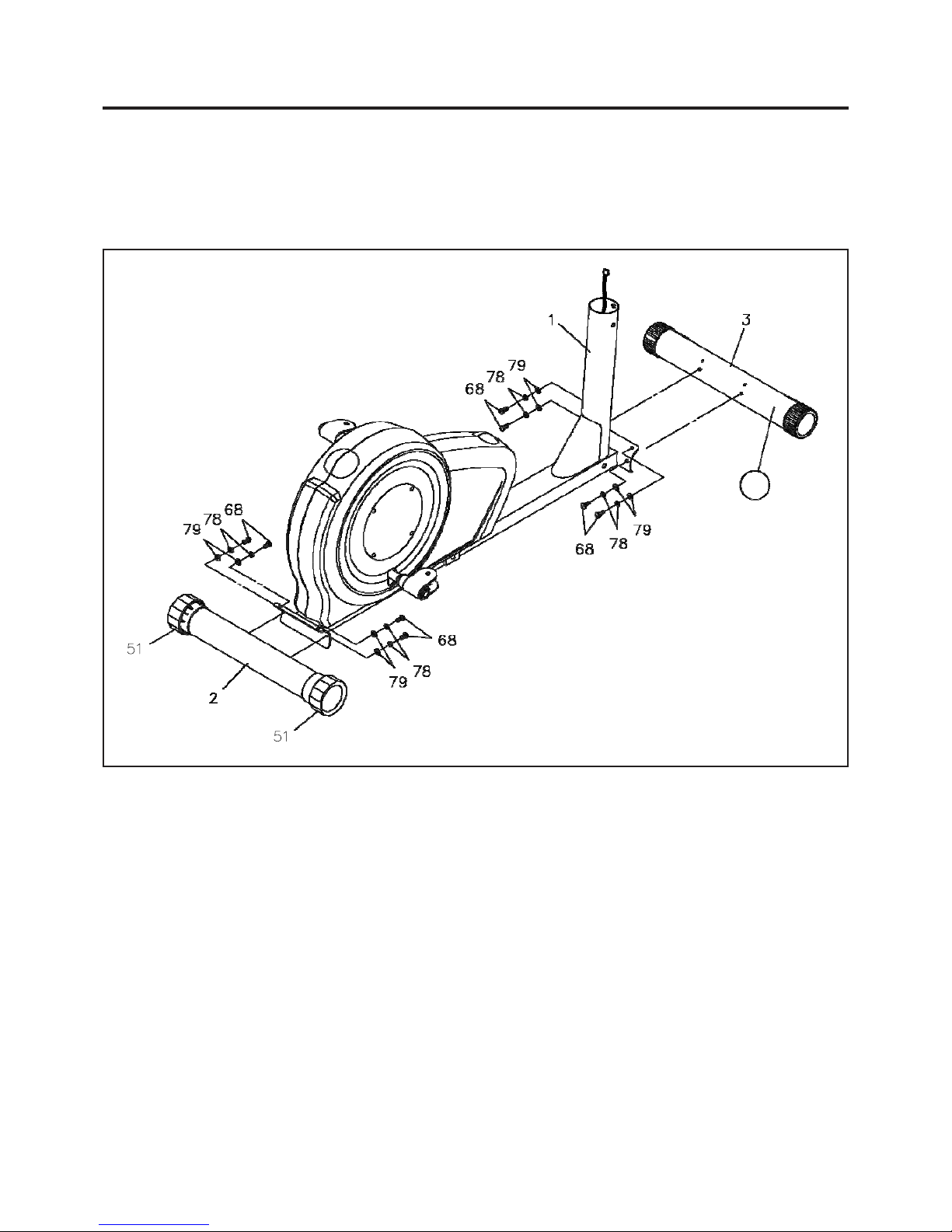
STEP 1
There is a "R" decal on one end of the FRONT STABILIZER(3), the one with wheels.
Attach the
FRONT STABILIZER(3) onto the MAIN FRAME(1) with the "R" decal end at right side and
secure with
BUTTON HEAD BOLTS(M8 x 20mm)(68), LOCK WASHERS(M8)(78),
and
WASHERS(M8)(79).
STEP 2
Attach the REAR STABILIZER(2) onto the MAIN FRAME(1) with BUTTON HEAD
BOLTS
(M8 x 20mm)(68), LOCK WASHERS(M8)(78), and WASHERS(M8)(79).
NOTE:
You can adjust the
LEVELING CAPS(51) on the REAR STABILIZER(2) to keep the Elliptical
stable.
4
ASSEMBLY INSTRUCTIONS
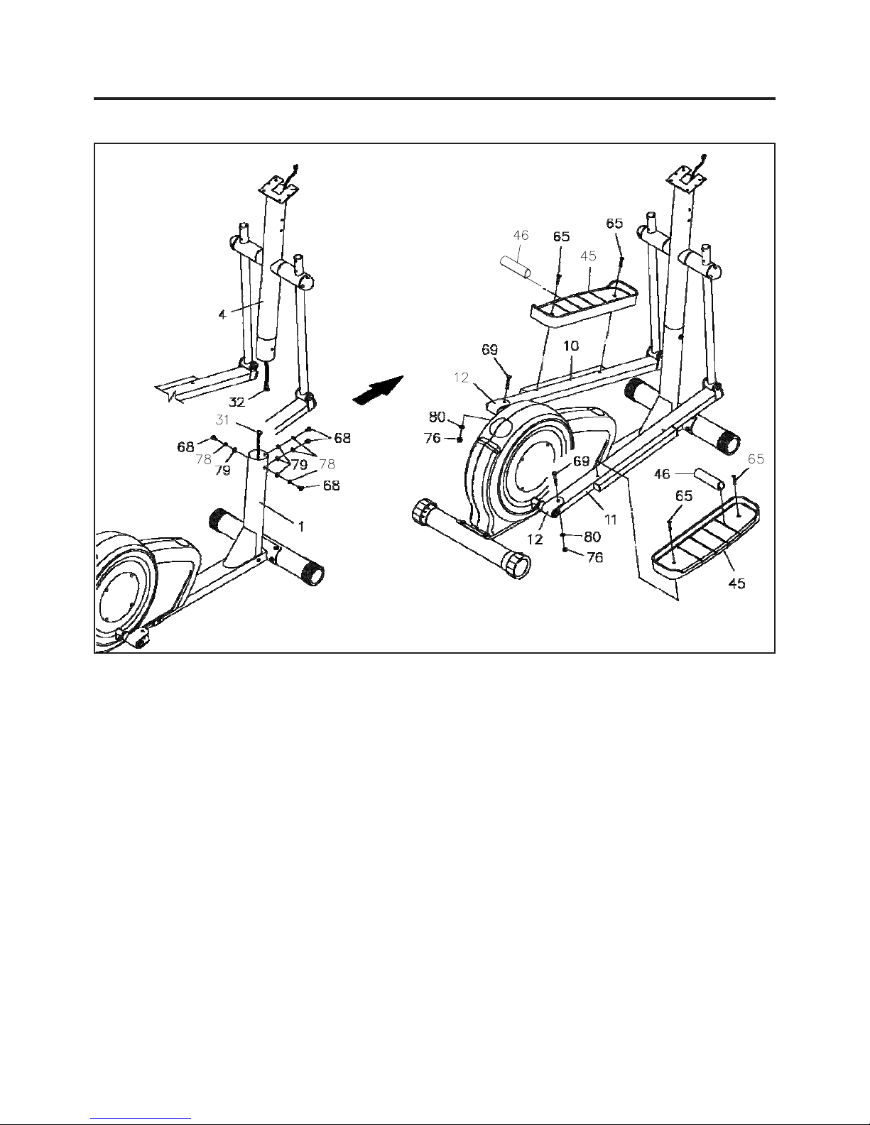
STEP 3
Connect the LOWER CONNECTION WIRE(31) to UPPER CONNECTION WIRE(32). Insert
the
UPRIGHT(4) onto the MAIN FRAME(1) and secure with BUTTON HEAD BOLTS(M8 x
20mm)(68), LOCK WASHERS(M8)(78),
and WASHERS(M8)(79).
STEP 4
Connect the LEFT and RIGHT PEDAL ARMS(10, 11) to the PEDAL ARM CONNECTORS(12) with
BUTTON HEAD BOL TS(M10 x 55mm)(69), W ASHERS(M10)(80), and NYLOCK NUTS(M10)(76).
STEP 5
Attach the PEDAL CAPS(45) onto the LEFT and RIGHT PEDAL ARMS(10, 11) with ROUND HEAD
BOLTS(M6 x 25mm)(65). Slide the PEDAL DIVIDERS(46) into one of the four slots on the
PEDAL CAPS(45) to fit your shoes. You may select the front or the back of the PEDAL
CAPS(45)
for foot placement. You will have more vertical movement in the Elliptical stride if you place
your feet at the back of
the
PEDAL CAPS(45).
CAUTION: The lip on the PEDAL CAPS(45) must face inside. The sides without a lip face outside as
shown.
5
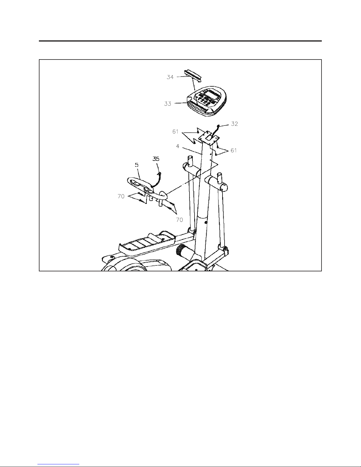
ASSEMBLY INSTRUCTIONS
STEP 6
Install four "C" size batteries into the COMPUTER(33), four batteries included. Plug the
UPPER CONNECTION WIRE(32) into the COMPUTER(33). Then attach the COMPUTER(33) onto
the plate
on the
UPRIGHT(4) with ROUND HEAD SCREWS(M5 x 10mm)(61). Press the
READING HOLDER(34) into the COMPUTER(33).
STEP 7
Attach the STATIONARY HANDLEBAR(5) onto the UPRIGHT(4) with FLAT HEAD
BOLTS
(M6 x 40mm)(70). Plug the PULSE PLUG WIRE(35) into the back of the COMPUTER(33).
6
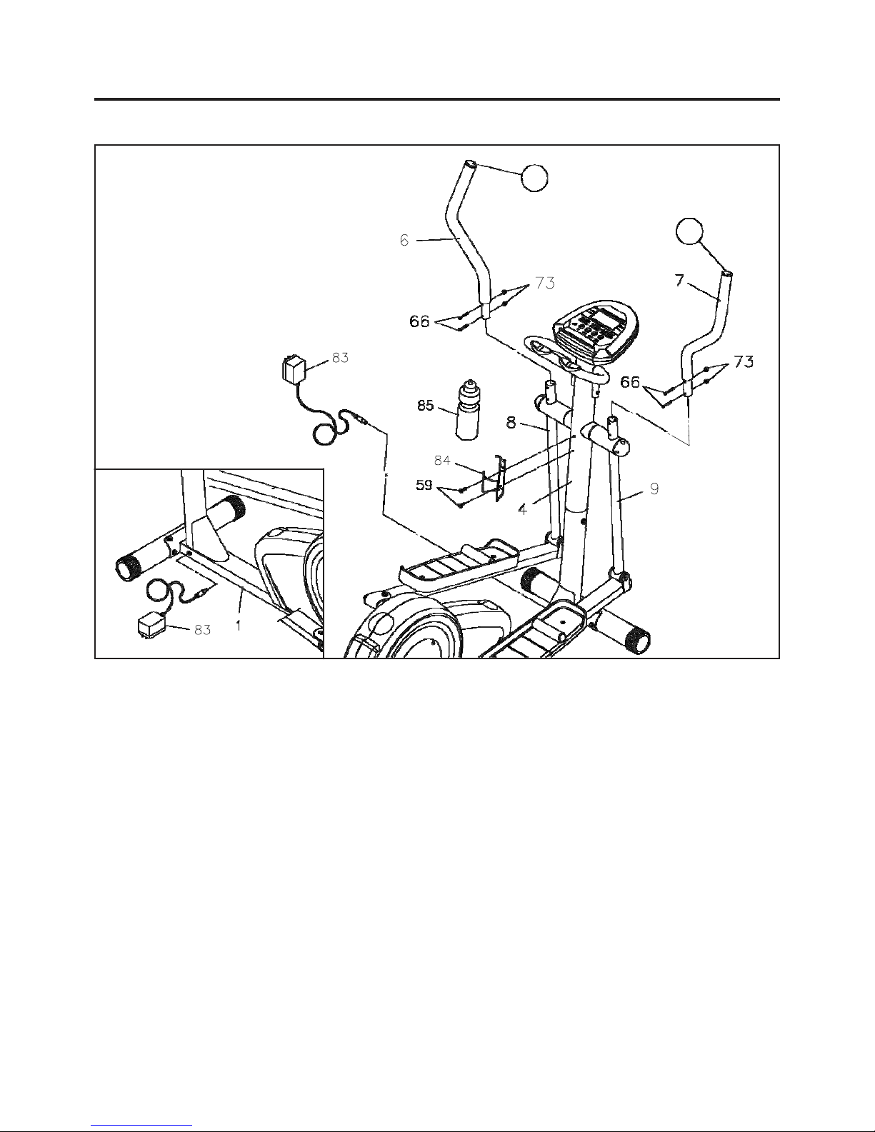
ASSEMBLY INSTRUCTIONS
L
R
STEP 8
There is a "L" decal on the LEFT HANDLEBAR(6), and a "R" decal on the RIGHT HANDLEBAR(7).
Insert the LEFT HANDLEBAR(6) onto the LEFT PIVOTING ARM(8) a nd secure with ROUND HEAD
BOLTS(M6 x 35mm)(66)
and NYLOCK NUTS(M6)(73). Repeat on the right side.
STEP 9
Attach the MOUNTING BRACKET(84) onto the UP RIGHT(4) with ROUND HEAD
SCREWS
(M5 x 12mm)(59). Place the WATER BOTTLE(85) into the MOUNTING BRACKET(84).
STEP 10
Connect the ADAPTER(83) into the outlet located on the base of the MAIN FRAME(1), refer to the inset
drawing. Plug the
ADAPTER(83) into an ele ctrical outlet .
NOTE:
The ELLIPTICAL can use the ADAPTER(83) or the batteries in the COMPUTER(33) as a
power source. To save battery power, use the
ELLIPTICAL with the ADAPTER(83)
plugged into an electrical outlet.
7
 Loading...