

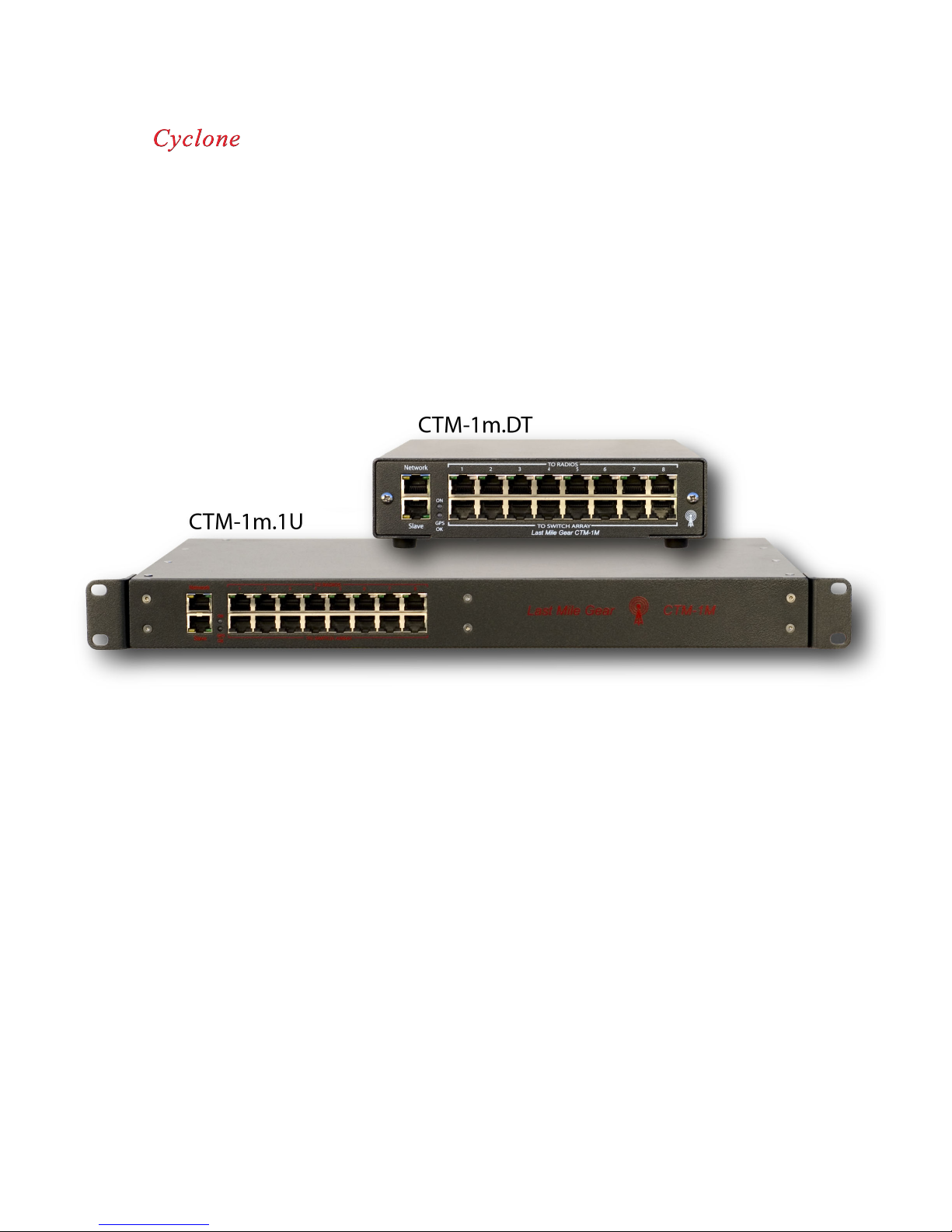
CyClone CTM-1m.DT, CTM-1m.1U User Manual
CYCLONE TIMING MODULE
1
0
1
1
1
1
1
1
1
1
1
1
1
1
1
1
1
1
1
1
1
1
1
1
1
1
1
1
1
1
1
0
0
0
0
0
0
0
0
0
0
0
0
0
0
0
0
0
0
0
0
0
0
0
0
0
0
0
1
1
1
1
1
1
1
0
0
0
0
0
0
0
0
1
1
0
0
0
0
0
0
0
0
0
0
0
0
0
0
0
0
0
0
0
0
0
0
0
0
0
0
0
0
0
0
0
0
0
0
0
0
0
0
0
0
0
0
0
0
0
0
0
0
0
0
0
0
0
0
0
0
0
0
0
0
0
0
0
0
0
0
0
0
0
0
0
0
0
0
0
0
0
0
0
0
0
0
0
0
0
0
0
0
0
0
0
0
0
0
0
0
0
0
0
0
0
0
0
0
0
0
0
0
0
0
0
0
0
0
0
0
0
0
0
0
0
0
0
0
0
0
0
0
0
0
0
0
0
0
0
0
0
0
0
0
0
0
0
0
0
0
0
0
0
0
0
0
0
0
0
0
0
0
0
0
0
0
0
0
0
0
0
0
0
0
0
0
0
0
0
0
0
0
0
0
1
1
1
1
1
1
1
1
1
1
1
1
1
1
1
1
1
1
1
1
1
1
1
1
1
1
1
1
1
1
1
1
1
1
1
1
1
1
1
1
1
1
1
1
1
1
1
1
1
1
1
1
1
1
1
1
1
1
1
1
1
1
1
1
1
1
1
1
1
1
1
1
1
1
1
1
1
1
1
1
1
1
1
1
1
1
1
1
1
1
1
1
1
1
1
1
1
1
1
1
1
1
1
1
1
1
1
1
1
1
1
1
1
1
1
1
1
1
1
1
1
1
1
1
1
1
1
1
1
1
1
1
1
1
1
1
1
1
1
1
1
1
1
1
1
1
1
1
1
1
1
1
1
1
1
1
1
1
1
1
1
1
1
1
1
1
1
1
1
1
1
1
1
1
1
1
1
1
1
1
1
1
1
USER GUIDE
Version 3.0
May 2007

Getting Started
Plug in your CTM using either the primary or secondary power supply port. Connect your PC to the “network” port on the front of
the unit via a standard CAT5 cable and your computers NIC card. Once you have established an Ethernet connection, you can
access the web interface at the default IP address (169.254.1.1).
Using the CTM Control Panel, you can now navigate the various configuration and status pages within the CTM user interface.
CTM Main Page
The first page displays the current CTM network settings and readings from the GPS receiver on board.
Basic Information
Site name: When set, this field will display the name or location entered under the general system setup page.
Date: Displays the current date when CTM is connected to the GPS antenna, and has proper GPS lock.
Time: Displays corrected time when CTM is connected to the GPS antenna, and has proper GPS lock. Time correction can be
adjusted to display current time in any time zone from General System Setup page.
Alert: Displays current state of alarm for quick reference.
MAC Address: Displays MAC address of CTM. Address is permanent, and can not be altered or changed by the user.
Flash Memory: Upon startup, the CTM will perform a checksum of the primary memory location containing the user interface
and operating files. In the event that memory location “A” is corrupt, the CTM will boot up using location “B” and display a failed
checksum for location “A”. If both memory banks have been corrupted, the CTM will boot up in Flash Loader mode. In the event
of a simultaneous failure of both memory banks contact Last Mile Gear Technical Support at +1(360) 414-5990 or support@lastmilegear.com.
Password Set: Displays current state of password security. Password system OFF is default, with no password set. Password security can be enabled by entering the desired code in the Change Password page. Once set, this field will display CTM Password
lock is ON.
Interface Version: Shows current version of web interface operating software.
Control CPU: Shows current version of CPU software load.
Flash Loader Version: Shows current version of firmware upload software.
Hardware Version: Shows current version of CTM circuit board.
Radio Power Status: This window will display the current status of all 8 radio ports
Status: Here you will find the current state of power for each port. The ON condition will be displayed in green, and shows that
this port is currently being powered. The OFF condition shows that this port is currently not powered and is shown in black. When
this field displays the red TRIP status, the radio port has shorted out causing the CTM to automatically turn off power to this port.
Power can be restored in the CTM Radio Setup page.
Sync: Displays current state of sync for each port. The ON condition shows that the sync pulse is being fed to the radio connected
to the corresponding port. The OFF condition shows that the sync pulse is disabled and an uninterrupted 24VDC is being fed to
the corresponding radio. Sync can be turned off and on for each port on the Radio Setup page.
Radio Power: This column will display the current power draw in Watts from each port.
Radio Name: This column will display the user defined name for each port. The user can edit these fields in the CTM Radio Setup
page.

Network & Email Setup
IP Address: Displays the current IP address assigned to the CTM. The user can change the IP in the Network Setup page. Default
IP setting is 169.254.1.1.
Subnet Mask: Displays the current subnet mask set in the CTM. The user can change this parameter in the Network Setup page.
Default setting is 255.255.255.0.
Gateway: Displays the current gateway IP address set in the CTM. The user can change this address in the Network Setup page.
Default gateway IP setting is 169.254.0.0.
DNS1: Displays the current primary DNS address set in the CTM. The user can change the address in the Network Setup page.
Default DNS setting is 0.0.0.0.
DNS2: Displays the current secondary DNS address set in the CTM. The user can change the address in the Network Setup page.
Default DNS setting is 0.0.0.0.
SNMP Target: Displays the current SNMP target address and port number set in the CTM. The user can change the address in
the Network Setup page. Default setting is 0.0.0.0:162.
SNMP Community Str: Displays the current SNTP community string set in the CTM. The user can change this setting in the Network Setup page. Default community string is public.
SMTP Port: Displays the current SNTP port set in the CTM. The user can change the port number in the Network Setup page.
Default port number is 25.
From Email: The current email address in which CTM alerts will be sent from.
Send To 1: Primary email address for email alert recipient. All alarms and settings changes will have an email generated and sent
to this Email address. The user can change this setting in the Network Setup page.
Send To 2: Secondary email address for email alert recipient. All alarms and settings changes will have an email generated and
sent to this Email address when entered. Changes for this setting can be made in the Network Setup page.
GPS Receiver Status & Environment
Timing: Here the status of the GPS timing pulse will be displayed. If the antenna is tracking more than 3 satellites, the CTM will
display FIX. When the GPS receiver can see WAAS enabled satellites, the CTM will display WAAS LOCK in this location. If no
satellites can be seen by the receiver, NO-FIX will be displayed.
Antenna Power: Displays the status of the antenna. The antenna must be connected prior to the CTM being powered up. Otherwise the CTM will not recognize the antenna.
SATS: Displays the number of satellites the GPS receiver can currently see. At least 6 satellites must be visible to the CTM for
proper GPS timing.
Sig S/N (dB): This field displays the current GPS signal to noise level in dB. Antenna S/N noise floor needs to be about 35db in
order to locate satellites. The number you see displayed on the web page is an averaged for different 4 satellites that the GPS is
using for mathmatical calculations. Ideally you want is to see 6 to 8 satellites being tracked. The S/N number will drop off dramatically, suddenly, when the cable gets too long, but is more an indicator of spectrum noise around the antenna. You should see the
S/N in the 45 to 50db range, about 55 is max. If you have low S/N and a reasonable-length cable (and a working antenna) then the
problem is either a bad cable joint or too much noise in the GPS spectrum (around 1.5GHz). You may also experience some rain
fade issues but this is generally limited to instances of the most extreme percipitation. Water in the antenna cable will rapidly kill the
GPS signal also. As you also found out, the antenna has to have a clear view of the sky, as much as possible.
Latitude: Displays current latitude position of CTM gathered from the GPS receiver. You must have visability of at least 4 satellites
before this field will show actual coordinates.
 Loading...