

Page 1

ASSEMBLY AND INSTALLATION INSTRUCTIONS
R7000
10, 12, 15, 17, 20, 30, 40 Meters
COMMUNICATIONS ANTENNAS
951465 (6/98)
Page 2

R7000
THIS ANTENNA IS AN ELECTRICAL CONDUCTOR. CONTACT WITH POWER LINES CAN RESULT IN DEATH, OR SERIOUS INJURY. DO NOT
WARNING
INSTALL THIS ANTENNA WHERE THERE IS ANY POSSIBILITY OF CONTACT WITH HIGH VOLTAGE OR ARC-OVER FROM POWER CABLES
OR SERVICE DROPS TO BUILDINGS. THE ANTENNA, SUPPORTING MAST AND/OR TOWER MUST NOT BE CLOSE TO ANY POWER LINES
DURING INSTALLATION, REMOVAL OR IN THE EVENT PART OF THE SYSTEM SHOULD ACCIDENTALLY FALL. FOLLOW THE GUIDELINES
FOR ANTENNA INSTALLATIONS RECOMMENDED BY THE U.S. CONSUMER PRODUCT SAFETY COMMISSION AND LISTED IN THE ENCLOSED
PAMPHLET.
Your Cushcraft R7000 vertical antenna is designed and manufactured to give trouble free service. This antenna will perform as specified if
the instructions and suggestions in this manual are followed and care is used in the assembly and installation. When checking the components
received in your antenna package use the parts listed beside each diagram. There is a master parts list on page 2. If you are unable to locate
any tube or component, check the inside of all tubing. IMPORTANT: Save the weight label from the outside of the carton. Each antenna is
weighed at the factory to verify the parts count. If you claim a missing part, you will be asked for the weight verification label.
Plan your installation carefully. If you use volunteer helpers be sure that they are qualified to assist you. Make certain that everyone involved
understands that you are the boss and that they must follow your instructions. If you have any doubts at all, employ a professional antenna
installation company to install your antenna.
Although the R7000 will operate in almost any location, it will perform best if it is mounted vertically and located in the clear away from surrounding
objects such as buildings, trees, power lines, towers, guy wires, antennas and metallic objects. The R7000 should not be attached to a ground
radial system. Failure to heed these points will possibly degrade performance, detune the antenna and increase VSWR.
EXTREME CARE MUST BE USED FOR YOUR SAFETY. YOU MUST INSURE THAT WHILE THE R7000 IS IN OPERATION NEITHER
PEOPLE OR PETS CAN COME IN CONTACT WITH ANY PORTION OF YOUR ANTENNA INCLUDING THE COUNTERPOISE RODS.
DEADLY VOLTAGES AND CURRENTS MAY EXIST. ALSO, SINCE THE EFFECTS OF EXPOSURE TO RF ARE NOT FULLY UNDERSTOOD,
LONG TERM EXPOSURE TO INTENSE RF FIELDS IS NOT RECOMMENDED. THERE ARE SEVEN WARNING STICKERS WHICH MUST
BE ATTACHED TO THE ENDS OF THE COUNTERPOISE RODS AS SHOWN IN FIGURE 2.
Your mast should be rigid and pointing straight up. Always use a mast at least 1-3/4 inches (4.4 cm) but not larger than 2-1/8 inches (5.4 cm)
in diameter. If you guy the mast, use non-conducting guy wires.
Direct grounding of the antenna mast is very important. This serves as protection from lightning strikes and static buildup, and from high voltages
which may be present in the equipment attached to the antenna. A good electrical connection should be made to one or more ground rods
directly at the base of the antenna or mast using a least #10 AWG ground wire and non-corrosive hardware. For details and safety standards,
consult the National Electrical Code. You should also use a coaxial lightning arrestor. Cushcraft offers several different models, such as the
LAC-1, LAC-2 or the LAC-4 series.
Assemble your R7000 by following steps 1 through 5. After assembling the antenna, verify all dimensions in figure F for accuracy. Then return
to the adjustment section below for final tuning.
The dimensions in figure F normally allow proper operation on all the bands. However, some variations may occur from one location to another.
Adjustments must be made from the bottom of the antenna to the top. Adjusting the antenna from top to bottom will not work. This is because
the settings at the top are severely affected by the adjustments at the bottom.
We suggest measuring the VSWR of your antenna by using the SWR meter in your transceiver. If your transceiver does not have one, use a
good quality VSWR bridge for this application. We will begin with 10 meters since this is at the bottom of the antenna. Set your transceiver at
your favorite frequency on 10 meters. Key the rig and check your VSWR. The R7000 is extremely broadbanded on 10 meters and seldom
needs adjustment. If the VSWR is low enough (below 1.5:1) then move on to the 12 meter band. If the 10 meter VSWR is not low enough,
adjust the antenna as follows: Check several frequencies on 10 meters to find the frequency of lowest VSWR. If the frequency of lowest VSWR
is above your favorite frequency, lengthen dimension A (figure F) by 1 inch (2.5 cm). This should lower the frequency of lowest VSWR by 50
to 100 KHz. If the frequency of lowest VSWR is below your desired frequency, shorten dimension A (figure F) by 1 inch (2.5 cm). Check your
desired 10 meter operating frequency again to see if the VSWR is less than 1.5:1. Repeat this procedure until the VSWR at your desired
frequency is low enough. Adjusting Dimension A is also used to move the resonant frequency of 12m.
Continue this procedure by selecting your desired frequency on 15 meters and checking the VSWR there. Dimension B (figure F) should be
used to adjust the VSWR on 15 meters.
The balance of the antenna should be adjusted in a like manner. The dimensions and the bands that they effect are shown in figure F. On 10
through 30 meters 1 inch (2.5 cm) of change in length will change the operating frequency by 50 to 100 KHz. On 30 and 40 meters the change
will be 15 to 25 KHz per inch (5 to 10 KHz/cm). When the antenna is completely adjusted, check all fasteners to be sure they are tight. Improving
VSWR's that are less than 2:1 will not noticeably improve station performance.
Remember to shorten this dimension to raise the frequency or lengthen it to lower the frequency.
PLANNING
LOCATION
MOUNTING
SYSTEM GROUNDING
ASSEMBLY
ADJUSTMENT
1
Page 3

R7000
Following the guidelines in the location and adjustment sections above, place the antenna on its mast in its final operating location. If you plan
to install the antenna in a salty or corrosive environment, you may want to consider coating it with a clear marine varnish or equivalent
final assembly and adjustment has been completed.
and the helpful hints below.
• Try to locate your R7000 as far away from TV antennas and their feedlines as possible. This will help to avoid overloading your television
with RF.
• The dimensions recommended in figure F are based on mounting the R7000 approximately 8 feet (2.4 meters) above the ground and 25
feet (7.5 meters) from surrounding objects. Antennas installed with less clearance may require additional adjustments.
• If you check the resistance across the coax connector on your R7000 you will find a DC short. This is normal. It does not mean that the
RF path is short circuited. It is approximately 50 Ohms at your operating frequencies.
• High VSWR is sometimes caused by poor contact between the matching network and the counterpoise rods. Make sure that corrosion has
not formed on the jumper strap terminals. Check to insure the hardware is tight.
• If your R7000 is very close to your shack you may experience RF on the feedline. Try lengthening your feedline several feet, placing an RF
ferrite bead on the coax, winding the feedline on a toroid or winding the coax in a 10 turn coil 8 inches (20 cm) in diameter.
• Weather sealing the matching network is not necessary. We have provided a large hole near the coax connector to allow air to circulate
through the box and to keep it dry. Keep this hole clear to avoid difficulties caused by humidity and condensation.
• Long periods (2 minutes or longer) of key down operation, such as RTTY, at high power (over 1000 Watts) may damage your R7000.
INSTALLATION
after
Now connect your transceiver. If you have any difficulties, reread the information above
HELPFUL HINTS
MASTER PARTS LIST
KEY PART# DESCRIPTION QTY
BA Base assembly 1
BB 1-1/4" x 48" (3.2 x 121.9 cm) aluminum tube slotted 1
one end
BC 1" x 48" (2.5 x 121.9 cm) aluminum tube slotted one end 1
BD 7/8" x 5" (2.2 x 12.7 cm) aluminum tube slotted 1
both ends
BE 7/8" x 16" (2.2 x 40.6 cm) aluminum tube slotted both ends 2
BG 3/4" x 48" (1.9 x 121.9 cm) aluminum tube 1
BH 5/8” x 6-1/2” (1.6 x 16.5 cm) aluminum tube 1
BI 5/8” x 7-3/4” (1.6 x 19.7 cm) aluminum tube 1
CT1 10/12 meter trap assembly 1
CT2 15/17 meter trap assembly 1
CT3 20/30 meter trap assembly 1
XHR 3/16" x 36" (.48 x 91.4 cm) aluminum rod drilled center 2
MN7000 Matching network 1
12 050012 3/4" (1.9 cm) plastic cap 1
26 190026 7/8" (2.22 cm) formed aluminum bracket 2
28 190028 Aluminum halfwasher 2
32 902832 49" (124.5 cm) stainless steel radial rod 7
63 170063 2" aluminum V-block 4
73 194173 Radial ring bracket 4
KEY PART# DESCRIPTION QTY
74 194174 Radial ring 2
79 010079 #8-32 x 1/2" (1.3 cm) stainless steel machine screw 4
87 014387 #8 stainless steel/nylon lock nut 22
88 014388 #10 stainless steel/nylon lock nut 1
89 014389 5/16" (.8 cm) stainless steel/nylon lock nut 8
96 010096 #8-32 x 3/8" (.95 cm) stainless steel machine screw 4
115 050115 Connector boot 1
116 240116 Silicone package 1
120 010120 #8-32 x 2" (5.1 cm) stainless steel machine screw 1
160 190160 Matching network upper bracket 1
231 010231 #8-32 x 1-3/4" (4.4 cm) stainless steel machine screw 2
232 010232 #8-32 x 2-1/2" (6.3 cm) stainless steel machine screw 6
326 290326 Warning label 8
404 010404 2-7/16" x 3-1/4" (6.2 x 8.3 cm) stainless steel U-bolt 2
405 010405 2-7/16" x 4-1/2" (6.2 x 11.4 cm) stainless steel U-bolt 2
410 030410 1" (2.5 cm) stainless steel worm clamp 6
411 030411 1-1/4" (3.2 cm) stainless steel worm clamp 1
412 030412 1-1/2" (3.8 cm) stainless steel worm clamp 1
413 030413 1-3/4" (4.4 cm) stainless steel worm clamp 1
428 902428 Jumper strap 1
4079 194079 Aluminum mounting plate 1
2
Page 4
R7000
FIGURE
A
FIGURE
B
FIGURE
C
73
87
96
Shorter dimension
attaches to radial
ring.
Longer
dimension
attaches to
base.
79
73
73
73
79
87
96
73
428
74
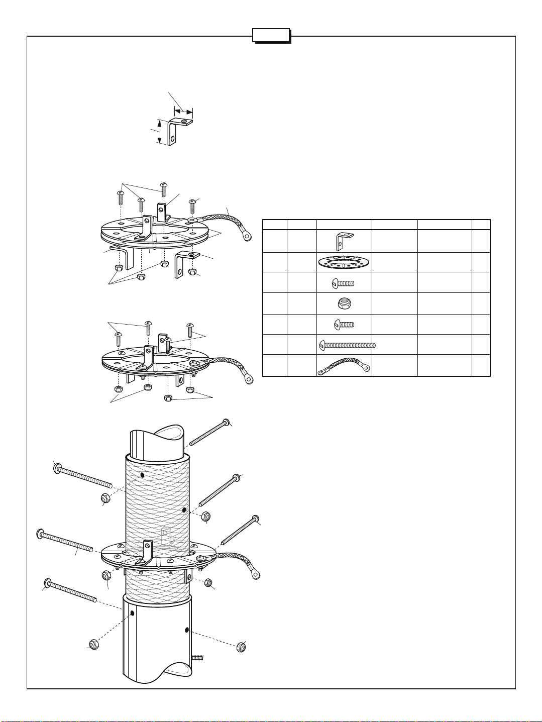
#1 - ASSEMBLE AND
ATTACH RADIAL RING
Figures A through D show the steps for radial ring assembly. Refer to
the Radial Ring Subassembly Parts List for the parts required in this
step. Attach the rings(74) to the base using the radial ring brackets (73),
2-1/2" (6.3 cm) screws (232), 1/2" (1.3 cm) screws (79) and lock nuts
(87). Leave hardware loose until Step #2. Note the proper orientation
of the radial ring brackets in Figure A. Install jumper strap (428) as
shown in Figure D.
NOTE: Do not accidentally use the #10-24 nut in this step.
Insert four 2-1/2" (6.3 cm) screws (232) into the base assembly (BA) as
shown in Figure D. Secure with nuts (87).
KEY P/N DISPLAY DESC SIZE QTY
73 194173 RADIAL RING 4
74 194174 RADIAL RING 2
79 010079 SS MACHINE 8-32 x 1/2" 4
87 014387 SS/NYLON 8-32 14
96 010096 SS MACHINE 8-32 x 3/8" 4
232 010232 SS MACHINE 8-32 x 2-1/2" 6
428 902428 STRAP 1
BRACKET
SCREW (1.3 cm)
LOCK NUT
SCREW (.95 cm)
SCREW 6.35 cm)
232
232
87
FIGURE
D
87
232
87
87
87
87
232
232
232
87
87
3
Page 5
R7000
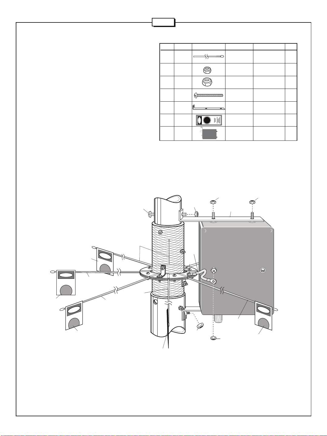
#2 - ATTACH MATCHING
NETWORK AND RADIALS
One at a time, place the stainless steel radial rods into the
slots of the radials rings. Tighten the corresponding ring
screws as you work your way around the rings. The radial
rings do not have to touch each other to secure the radial
rods properly so do not overtighten the screws. When all 7
radial rods are secure, tighten the two screws holding the
radial ring brackets to the base. Attach warning labels (326)
as shown in Figure E.
Attach matching network upper bracket (160) to base assembly
(BA) using screws (120) and nuts (87). Attach MN7000 to
base assembly by inserting the two 8-32 mounting screws
into the upper bracket (160) and securing screws with two
nuts (87). Place bottom of MN7000 over the 10-24 captive
screw and secure with nut (88). Connect braid from radial
ring to MN7000 screw as shown using nuts (87).
FIGURE
E
120
KEY P/N DISPLAY DESC SIZE QTY
32 902832 SS RADIAL 49" 7
87 014387 SS/NYLON 8-32 4
88 014388 SS/NYLON 10-24 1
120 010120 SS MACHINE 8-32 x 2" 1
160 190160 MN7000 1
326 290326 WARNING 7
MN7000 MATCHING 1
87
LOCK NUT
LOCK NUT
SCREW (5.1 cm)
BRACKET
LABEL
NETWORK
87
160
(124.5 cm)
87
326
326
326
32
32
32
32
326
28
88
MN7000
87
32
326
4
Page 6
X
Y
2"
(5 cm)
min.
2"
(5 cm)
min.
R7000
87
87
231
231
26
28
37
37
26
28
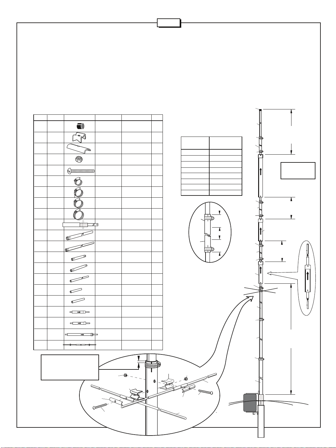
capped end up and slide bottom tube into section BC until it is stopped by
#3 - ASSEMBLE RADIATOR
Place worm clamp (413) over top end of base assembly (BA). Note
Figure G for proper positioning of all worm clamps. Slide section BB
into BA 4 inches and secure worm clamp. Place worm clamp (412)
over slots of section BB. Slide section BC into BB 4 inches and secure
worm clamp. Attach capacity hat rods (XHR) to BC using hardware
shown in Figure G. Place worm clamp (411) over slots of section BC.
Before sliding Trap CT1 into BC, insert tube BH into the the bottom
tube of CT1 and BI into the top tube of CT1. The screws holding the
XHR rods will keep tube BH in place. Hold trap assembly CT1 with
KEY P/N DISPLAY DESC SIZE QTY
12 050012 PLASTIC 3/4" 1
26 190026 ALUMINUM 7/8" 2
28 190028 ALUMINUM 2
87 014387 SS/NYLON 8-32 2
231 010231 SS MACHINE 8-32 x 1-3/4" 2
410 030410 SS WORM 1" 6
411 030411 SS WORM 1-1/4" 1
412 030412 SS WORM 1-1/2" 1
413 030413 SS WORM 1-3/4" 1
BA BASE 1
BB ALUMINUM 1-1/4" x 48 1
BC ALUMINUM 1" x 48" 1
BD ALUMINUM 7/8" x 5" 1
BE ALUMINUM 7/8" x 16" 2
BG ALUMINUM 3/4" x 48" 1
BH ALUMINUM 5/8” x 6-1/2” 1
BI ALUMINUM 5/8” x 7-3/4 1
CT1 10/12 M 1
CT2 15/17 M 1
CT3 20/30 M 1
XHR ALUMINUM 3/16" x 36" 2
Secure hose clamps about
1/4" from top of each slotted
tube to ensure adequate
compression.
CAP (1.9 cm)
BRACKET (2.2 cm)
HALF WASHER
LOCK NUT
SCREW (4.4 cm)
CLAMP (2.5 cm)
CLAMP (3.2)
CLAMP (3.8 cm)
CLAMP (4.4 cm)
ASSEMBLY
TUBE (3.2 x 121.9 cm)
TUBE (2.5 x 121.9 cm)
TUBE (2.2 x 12.7 cm)
TUBE (1.9 x 121.9)
TUBE (1.6 X 16.5 cm)
TUBE (1.6 x 19.7 cm)
TRAP
TRAP
ROD (.5 x 91.4 cm)
FIGURE
TUBE(2.2 x 40.6cm)
TRAP
G
the XHR mounting screws and secure worm clamp. Place worm clamps
(410) over each end of section BD. Slide BD over CT1 top tube 2" and
secure worm clamp. Hold trap assembly CT2 with capped end up and
slide bottom tube into BD 2" and secure worm clamp. Place worm clamps
(410) over each end of section BD. Slide BD over CT2 top tube 3" and
secure worm clamp. Hold trap assembly CT3 with capped end up and
slide bottom tube into BD 3-1/2". Secure worm clamp. Place worm clamps
(410) over each end of section BD. Slide BE over CT3 top tube 5”(12.7
cm) and secure worm clamp. Slide BG into BE 2" (5.1 cm) and secure
worm clamp. Install cap (12) . Verify all radiator dimensions to within 1/4"
(.6 cm) using Figure F.
12
BG
CT3
Dimension C
18"
CT2
Dimension D
(40m)
See Chart A
FIGURE
F
(20 / 30m)
(45.7 cm)
Chart A
Dimension D Center Frequency
(in) (cm) (MHz)
53 134.5 7.300
54 137 7.275
56 142 7.225
58 147 7.175
60 152.5 7.125
62 157.5 7.075
64 162.5 7.025
65 165 7.000
410
BE
410
410
BE
410
BE
410
410
BD
Dimension B
15 / 17 m
(15.2 cm)
6"
NOTE: When installing BE
tube, ensure at least 2" (5
CT1
cm) length of the adjoining
3/4" (1.9 cm) tubes are
inserted into R7000BE
411
(Figure A, points X and Y).
BC
412
BH
Dimension A
BB
413
BA
10 / 12m
135"
(342.9 cm)
5
BI
Page 7
R7000
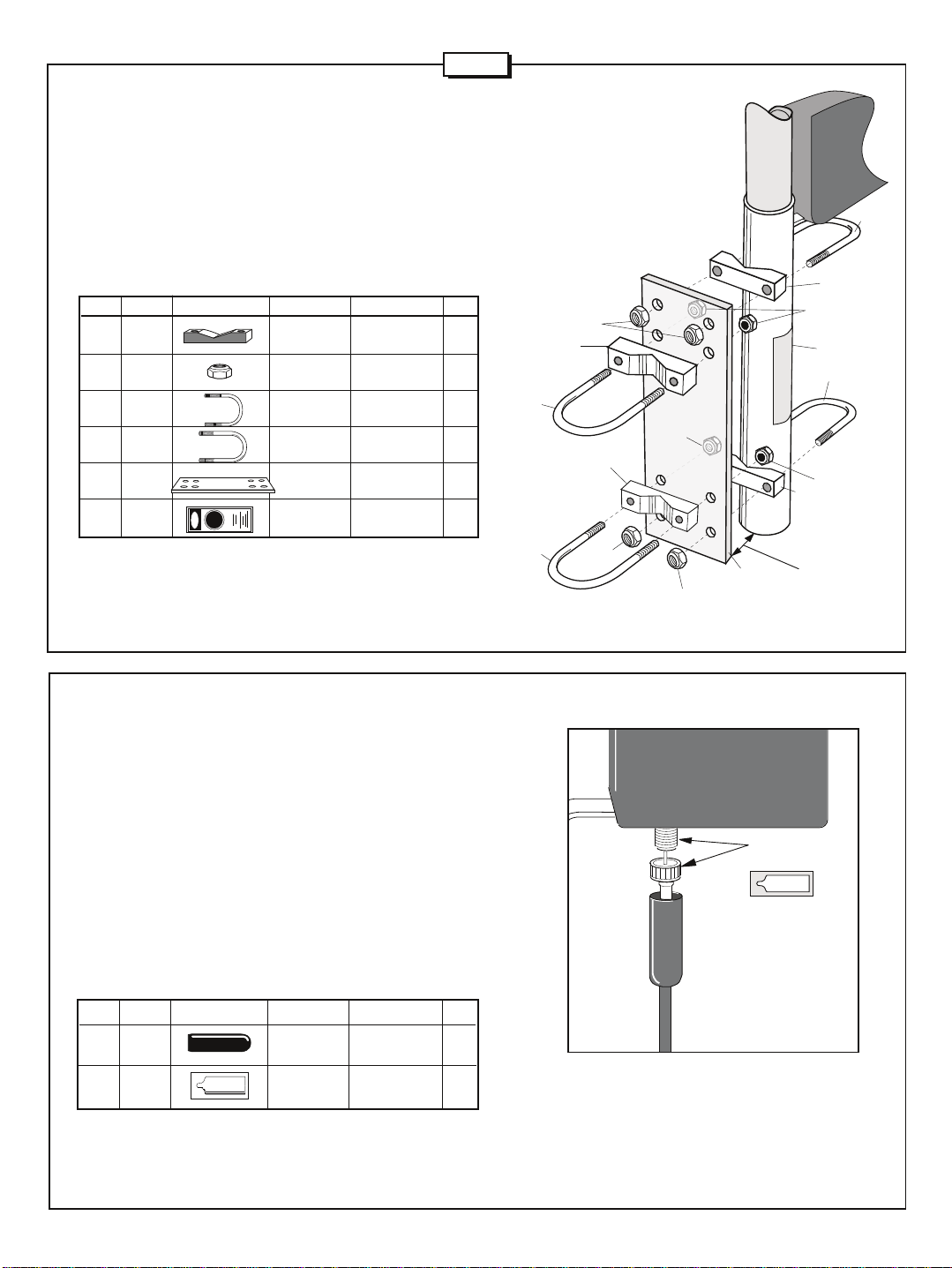
#4 - BASE TO MAST ASSEMBLY
Attach the antenna base to your mast as shown in Figure H. First attach
the mounting plate (4079) with U-bolts (404), aluminum V-blocks (63),
and nut (89) to the antenna base. The bottom of the plate should should
be even with the bottom of the antenna to leave room for the radial
clamping system. Affix danger label (326) to the antenna so that is easy
to see. When attaching mounting plate to the mast use the (405) Ubolts, aluminum V-blocks (63), and nut (89).
KEY P/N DISPLAY DESC SIZE QTY
63 170063 V-BLOCK 2" 4
89 014389 SS/NYLON 5/16" 8
404 010404 U-BOLT 2-7/16 x 3-1/4" 2
405 010405 U-BOLT 2-7/16" x 4-1/2" 2
4079 194079 MOUNTING 1
326 290326 WARNING 1
LOCK NUT (.8 cm)
PLATE
LABEL
(5.1 cm)
(6.2 x 8.2 cm)
(6.2 x 11.4 cm)
405
405
FIGURE H
89
63
63
89
404
63
89
326
404
89
89
63
119
4079
89
Line bottom
of plate up
with bottom
of antenna.
#5 - FEEDLINE
The R7000 is designed for use with 50 Ohm coaxial cable terminated
with a PL-259 connector. The shortest length of cable will have the
least loss. A connector boot is included for use with your new antenna
(figure I). Slide the boot over the cable before attaching your PL-259.
Coat only the outside connector threads and shell with silicone grease.
Do not coat the center pin or receptacle. After the PL-259 is firmly
screwed onto the antenna connector, slide the vinyl boot over the
connector and against the connector bracket for a good weather-tight
connection. After the antenna is on the mast, tape the feedline to the
mast. If you plan to install the antenna in a salty or corrosive environment,
you may want to consider coating it with a clear marine varnish or
equivalent after it is assembled. For final tuning see page 1.
KEY PART# DESCRIPTION SIZE QTY
115 050115 CONNECTOR 1
116 240116 SILICONE 1
cushcraft
SILICONE GREASE
BOOT
PACKAGE
SILICONE
(116)
SILICONE GREASE
cushcraft
115
DO NOT COAT
CENTER PIN
WITH SILICONE!
FIGURE
I
6
Page 8
SPECIFICATIONS
Frequency Coverage, meters 10, 12, 15, 17, 20, 30, 40
Gain, dBi 3
Electrical Wavelength each band Half-wave
VSWR 1.2:1 Typical
2:1 Bandwidth (KHz) 10m (1700), 12m (100), 15m (450), 17m (100)
Power Rating, Watts PEP 1500
Radiation Angle, degrees 16
Horizontal Radiation Pattern, degrees 360
Height, ft (m) 24 (7.31m)
Mast Size Range, in (cm) 1.75-2.125 (4.4-5.4 cm)
Wind Load, ft2 (m2) 2 (.2)
Weight, lb (kg) 18 (8.2)
20m (250), 30m (100), 40m (150)
Cushcraft Corporation, P.O. Box 4680, Manchester, New Hampshire 03108, warrants to the original purchaser for one year
LIMITED WARRANTY
from date of purchase that each Cushcraft antenna is free of defects in material or workmanship. If, in the judgement of
Cushcraft, any such antenna is defective, then Cushcraft Corporation will, at its option, repair or replace the antenna at
its expense within thirty days of the date the antenna is returned (at purchasers expense) to Cushcraft or one of its
authorized representatives. This warranty is in lieu of all other expressed warranties, any implied warranty is limited in
duration to one year. Cushcraft Corporation shall not be liable for any incidental or consequential damages which may
result from a defect. Some states do not allow limitations on how long an implied warranty lasts or exclusions or limitations
of incidental or consequential damages, so the above limitation and exclusion may not apply to you. This warranty gives
you specific legal rights, and you may also have other rights which vary from state to state. This warranty does not extend
to any products which have been subject the misuse, neglect, accident or improper installation. Any repairs or alterations
outside of the Cushcraft factory will nullify this warranty.
COMMUNICATIONS ANTENNAS
TELEPHONE: 603-627-7877 • FAX: 603-627-1764 • E-mail: [email protected]
48 PERIMETER ROAD, MANCHESTER, NH 03108 USA
SPECIFICATIONS SUBJECT TO CHANGE WITHOUT NOTICE
 Loading...