

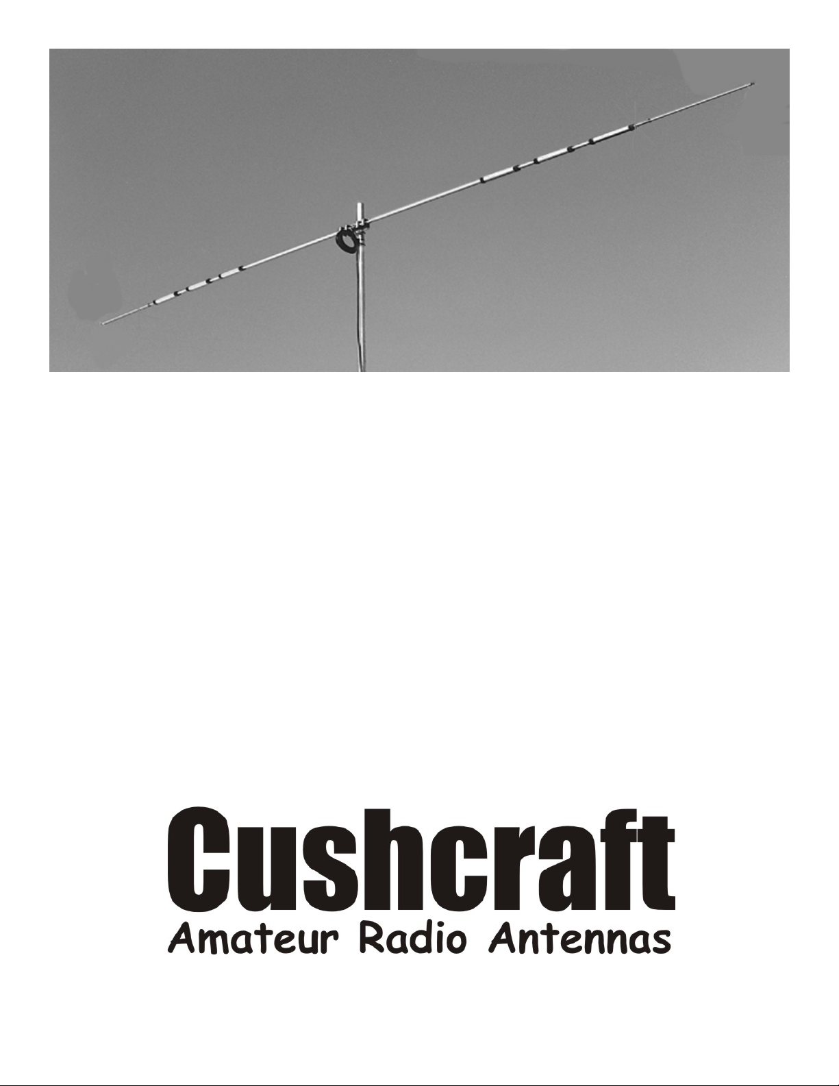
WORLD RANGER
ROTATABLE DIPOLE
D4 10, 15, 20, 40 METERS

Your Cushcraft Rotatable Dipole is designed and manufactured to give top performance and trouble free
service. The antenna will perform as specified if the instructions and suggestions are followed and care is used
in assembly and installation. When check the tubing received with your antenna package using the parts list, it
is easiest to identify the various dimensions of tubing by separating them into groups of the same diameter and
length.
MASTING
The mast mount bracket will accommodate up to a 2 1/8 in. OD [5.34 cm] mast.
ROTATOR
A good antenna rotator will provide the best service and longest life.
LOCATION
Location of the antenna is very important. Surrounding objects such as trees, power lines, other antennas, etc.
will seriously reduce efficiency. To minimize the effects of surround objects, mount the antenna as high and in
the clear as possible. If metal guy wires are used, they should be broken with strain insulators.
WARNING: THE ANTENNA IS AN ELECTRICAL CONDUCTOR; CONTACT WITH POWER LINES
CAN RESULT IN DEATH, OR SEROUS INJURY. DO NOT INSTALL THIS ANTENNA WHERE THERE
IS ANY POSSIBLITY OF CONTACT WITH OR HIGHT VOLTAGE ARC-OVER FROM POWER CABLES
OR SERVICE DROPS TO BUILDINGS. THE ANTENNA SUPPORTING MAST AND/OR TOWER MUST
NOT BE CLOSE TO ANY POWER LINES DURING INSTALLATION, REMOVAL OR IN THE EVENT
PART OF THE SYSTEM SHOULD ACCIDENTLY FALL. FOLLOW THE GUIDELINES FOR ANTENNA
INSTALLATIONS RECOMMENDED BY THE U.S. CONSUMER PRODUCT SAFETY COMMISSION
AND LISTED IN THE ENCLOSED PAMPHLET.
Plan your installation carefully. If you use volunteer helpers be sure that they are qualified to assist you. Make
certain that everyone involved understands that you are the boss and that they must follow your instructions. If
you have any doubts at all employ a professional antenna installation company to install your antenna.
MOUNTING
Several antennas may be mounted on the same mast. Short VHF/UHF Beams should be mounted at least 5 feet
from your Rotatable Dipole. Beams with similar boom lengths should be mounted one half the boom length
from each other, if practical.
SYSTEM GROUNDING
Direct grounding of the antenna, mast, and tower is very important. This serves as protection from lightningstrikes and static buildup, and from high voltage which is present in the radio equipment connected to the
antenna. A good electrical connection should be made to one or more ground rods (or other extensive ground
system) directly at the base of the tower or mast, using at least 10AWG ground wire and non-corrosive
hardware. For details and safety standards, consult the National Electrical Code. You should also use a coaxial
lightning arrester in your feedline.

ELEMENT ASSEMBLY
Lay out the element pieces for your rotatable dipole. Slide the 1 ¼” x 3 ¼” (3.2x8.3cm) sleeve over the drilled
end of EA (fig. 1) Insert the 5” (12.7cm) fiberglass insulator into the drilled end of EA. Secure it using machine
screws (123), lock washers (10) and nuts (11) (fig. 2). Tighten these firmly. Assemble the mount assembly over
the fiberglass insulator and sleeve using figure 3. Prepare your feedline as shown. The coaxial balun consists of
approximately 12 turns of your feed line in a coil approximately 6 inches (15 cm) in diameter.
Assemble the rest of the element using figure 4. Each piece of tubing should be inserted into the next larger
piece and secured with a clamp. The arrows on the traps should point toward the mount. Attach and tighten
clamp (88) on tubing piece (ED) and tighten it firmly.
The D4 is equipped with a support line assembly. The support line clamp should be attached about 3 ft. (1
meter) above the dipole’s mount point. Attach the support line to the dipole as show in the diagrams. Confirm
the dipole is horizontal before securing the support line.
FINAL CHECK
Now recheck your antenna dimensions. Your antenna is now ready for installation on your support. Note:
checking the VSWR near the ground will provide erroneous results. The antenna must be in a working position
for a good VSWR test.
WORLD RANGER DIPOLE SPECIFICATIONS
D40 D4 D3 DW3
BAND, METERS 40 10, 15, 20, 40 10, 15, 20 12, 16, 30
BANDWIDTH AT 200 350+ 500+ Entire Band
2:1 SWR, KHz 125 KHz on 40 m
SWR AT RESONANCE 1.5 to 1 1.5 to 1 1.5 to 1 1.5 to 1
POWER RATING; 2000 2000 2000 2000
WATTS PEP
LENGTH, FEET (M) 42.25 (12.88) 35.8 (10.92) 25.8 (7.86) 34.0 (10.37)
MAST DIAMETER MAX 2 (5) 2 (5) 2 (5) 2 (5)
INCHES (cm)
WIND LOAD, FEET (m2) 1.3 (.12) 1.3 (.12) .9 (.08) .9 (.08)
WEIGHT, LB. Kg. 12 (5) 13 (6) 9 (4) 11 (5)

D4 10, 15, 20, 40 METERS
STOCK NO. KEY DESCRIPTION SIZE QUANTITY
20-DIP-SL SL Sleeve 1 1/4 x 3 1/4" (3.2 x 8.3 cm) 2
010123 123 Machine Screw 8-32 x 1 1/2" (3.8 cm) 2
010010 10 Lockwasher #8 2
010011 11 Nut 8-32 2
124081 FG Insulator 5" (12.7 cm) 1
20-D34-EA EA Aluminum Tubing 1 1/8 x 48" (2.9 x 121.9 cm) 2
MOUNT CLAMP ASSEMBLY
STOCK NO. KEY DESCRIPTION SIZE QUANTITY
010719 719 Machine Screw 1/4-20 x 3" (7.6 cm) 8
010084 84 Lock Washer 1/4" (.64 cm) 8
010085 85 Nut 1/4-20 8
010010 10 Lock Washer #8 2
010011 11 Nut 8-32 2
190722 722 Mount Plate 4 x 10" (10.2 x 25.4 cm) 1
193384 384 Backing Plate 1 1/4 x 3 1/2" (3.2 x 8.9 cm) 4
190032 32 U-Bolt Bracket 3 1/2" (8.9 cm) 2
010404 404 U-Bolt 2 1/8 x 3" (5.4 x7.6 cm) 2
010118 118 Nut 5/16" (.8 cm) 4
010119 119 Lock Washer 5/16" (.8 cm) 4
100453 453 Terminal 12-10 AWG 2
153383 383 Insulator Block 2 1/2 x 3/4" (6.4 x 1.9 cm) 8

D4 ELEMENT
STOCK NO. KEY DESCRIPTION SIZE QUANTITY
010123 123 Machine Screw 8-32 x 1 1/2" (3.8 cm) 2
010010 10 Lock Washer #8 8
010011 11 Nut 8-32 4
060077 77 Black Plastic Cap 3/8" (.95 cm) 2
200088 88 Guy Line Clamp 1" (2.5 cm) 2
030410 410 Worm Clamp 1" (2.5 cm) 2
030411 411 Worm Clamp 1 1/8" (2.9 cm) 12
030408 408 Worm Clamp 1/2" (1.3 cm) 2
290326 326 Warning Label 1
20-D34-EB EB Aluminum Tubing 1 x 48" (2.5 x 121.9 cm) 2
20-A34S-EF EC Aluminum Tubing 1 x 5 1/4" (2.5 x 13.3 cm) 2
20-D4-ED ED Aluminum Tubing 1 x 18" (2.5 x 45.7 cm) 2
20-D4-EE EE Aluminum Tubing 1/2 x 24" (1.3 x 61 cm) 2
20-D4-EF EF Aluminum Tubing 3/8 x 48" (1 x 121.9 cm) 2
11-TA-B TA Trap 11" (27.9 cm) 2
11-TN TN Trap 12" (30.5 cm) 2
11-TK TK Trap 11" (27.9 cm) 2
20-DIP-SL SL Sleeve 1 1/4 x 3 1/4" (3.2 x 8.3 cm) 2
190028 28 Aluminum Half Washer 2
21-A743-XHR XHR Aluminum Rod 3/16 x 28 3/4" (.5 x 87.6 cm) 4
190157 157 Formed Aluminum Bracket 2 x 3/4" (5.1 x 1.9 cm) 2
190026 26 Bracket 7/8" (2.2 cm) 2

D4 SUPPORT ASSEMBLY
STOCK NO. KEY DESCRIPTION SIZE QUANTITY
010010 10 Lock Washer #8 2
010011 11 Nut 8-32 2
190032 32 Bracket 3 1/2" (8.9 cm) 1
010072 72 Machine Screw 8-32 x 3/4" (1.9 cm) 2
010118 118 Nut 5/16" (.8 cm) 2
010119 119 Lockwasher 5/16" (.8 cm) 2
010207 207 Washer 3/8" (1.9 cm) 4
010405 405 U-Bolt 2 x 4" (5.1 x 10.2 cm) 1
321045 1045 Space 1/2 x 1/2" (1.3 x 1.3 cm) 2
13-GUYLINE FN Guy Line 23' (3mm x 7.01 m) 1
320056 0056 Spacer 5/16 x 1/4" (.8 x .6 cm) 2

 Loading...