

Page 1

ASSEMBLY &
INSTALLATION
XM510
10 Meter Monoband Yagi
28.0-29.7 MHz
COMMUNICATIONS ANTENNAS
951479 (10/98)
Page 2

XM510
Thank you for your purchase of the Cushcraft XM510 . This antenna is designed and manufactured to give the best performance and trouble
free service. The antenna will perform as specified if the instructions are followed during assembly and installation. If you have technical questions
and have access to the World Wide Web you can visit Cushcraft’s
enables the user to place parts orders, ask technical questions, locate part numbers, initiate warranty inquires and review
Questions
at (603) 627-1764 or can be e-mailed at
WARNING
. Our technical support staff can be reached by phone at (603) 627-7877 (8 AM to 5 PM Eastern time or voice mail after hours), faxed
THIS ANTENNA IS AN ELECTRICAL CONDUCTOR. CONTACT WITH POWER LINES CAN RESULT IN DEATH OR SERIOUS INJURY.
DO NOT INSTALL THIS ANTENNA WHERE THERE IS ANY POSSIBILITY OF CONTACT WITH OR HIGH VOLTAGE ARC-OVER FROM
POWER CABLES OR SERVICE DROPS TO BUILDINGS. THE ANTENNA, SUPPORTING MAST AND/OR TOWER MUST NOT BE CLOSE
TO ANY POWER LINES DURING INSTALLATION, REMOVAL OR IN THE EVENT PART OF THE SYSTEM SHOULD ACCIDENTALLY FALL.
FOLLOW THE GUIDELINES FOR ANTENNA INSTALLA TION RECOMMENDED BY THE U.S. CONSUMER PRODUCT SAFETY COMMISSION
AND LISTED IN THE ENCLOSED PAMPHLETS.
Antenna System Planning
Before assembly, take time to review your installation plans for the antenna. Location of the antenna is very important. Surrounding objects such
as trees, power lines, buildings, and other antennas will interact with an HF Yagi. To minimize the effects of surrounding objects, mount the
antenna as high and in the clear as possible. Metallic guy wire within 30 feet of this antenna, if broken with strain insulators, will improve
performance.
YOU MUST INSURE THAT NEITHER PEOPLE OR PETS CAN COME IN CONTACT WITH YOUR ANTENNA WHILE IT IS IN
OPERATION. DEADLY VOLTAGES AND CURRENTS MAY EXIST. ALSO, SINCE THE EFFECTS OF EXPOSURE TO RF ARE NOT FULLY
UNDERSTOOD, LONG TERM EXPOSURE TO INTENSE RF FIELDS IS NOT RECOMMENDED. THERE IS A WARNING STICKER WHICH
MUST BE ATTACHED TO THE BOOM AS SHOWN IN FIGURE A
they are qualified to assist you. Make certain that everyone involved understands that you are in charge and that they must follow your instructions.
If you have any doubts at all, employ a professional antenna installation company to install your antenna.
System Grounding
Direct grounding of the antenna, mast and tower is very important. This serves as protection from lightning strikes and static buildup. A good
electrical connection should be made to one or more ground rods directly at the base of the tower or mast using at least #10 AWG ground wire
and noncorrosive hardware. For details and safety standards, consult the National Electrical Code. A coaxial lightning arrester should be used.
Cushcraft offers several different models such as the LAC series.
TECHEXPRESS
support service (http://www.cushcraft.com). The site
Frequently Asked
. Plan your installation carefully. If you use volunteer helpers be sure that
Assembly
The assembly procedure for the XM510 consists of assembling the following subassemblies. 1) Boom Assembly. 2) Element Assembly.
3) Element to Boom Assembly. 4) Feed System Assembly. 5)Boom to Mast Assembly. Assembly of the XM510 will be easiest if the
preceding steps are performed in the given order.
Please read through the entire assembly procedure before beginning.
Verification of Parts
Verify all parts are present by using the XM510 Master Parts List. Check off each part when it is counted. There are extra parts intentionally
shipped with this antenna. Place common hardware in temporary containers for ease of assembly. Note all hardware is Stainless Steel.
Part No. Description Metric Equivadent Quantity Qty Check
MNXM Matching Network . . . . . . . . . . . . . . . . . . . . . . . . . . . . . . . . . . . . . . . . . . . . . . . . . . . . . . . 1 ____
X79FS 6” feed strap . . . . . . . . . . . . . . . . . . . . . . . . . . . . . . . . . . . . . . . . . . . . . . . . . . . . . .15.2 cm 2 ____
XM510FL 5/8” x 49-5/8” . . . . . . . . . . . . . . . . . . . . . . . . . . . . . . . . . . . . . . . . . . . . . . . . 1.6 x 126 cm 2 ____
XM510EA 7/8” x 12” aluminum tube slotted both ends . . . . . . . . . . . . . . . . . . . . . . . . . 2.2 x 30.5 cm 3 ____
XM510EB 3/8” x 42” aluminum tube . . . . . . . . . . . . . . . . . . . . . . . . . . . . . . . . . . . . . . . .9 x 106.7 cm 8 ____
XM510EC 3/4” x 36” aluminum tube, swedged, slotted one end . . . . . . . . . . . . . . . . . 1.9 x 91.4 cm 4 ____
X79ED 3/4” x 36” aluminum tube, swedged, slotted one end . . . . . . . . . . . . . . . . . 1.9 x 91.4 cm 6 ____
X79EE 1/2” x 36” aluminum tube, slotted one end . . . . . . . . . . . . . . . . . . . . . . . . . . 1.3 x 91.4 cm 10 ____
X79EF 3/8” x 48” aluminum tube . . . . . . . . . . . . . . . . . . . . . . . . . . . . . . . . . . . . . . .4 x 121.9 cm 2 ____
XM510BA 2-1/2” x 48” aluminum tube, 4 holes . . . . . . . . . . . . . . . . . . . . . . . . . . . . . 6.3 x 121.9 cm 1 ____
XM510BB 2-1/2” x48” aluminum tube, 8 holes . . . . . . . . . . . . . . . . . . . . . . . . . . . . . . 6.3 x 121.9 cm 1 ____
XM510BC 2-1/2” x 60” aluminum tube, 10 holes . . . . . . . . . . . . . . . . . . . . . . . . . . . . 6.3 x 152.4 cm 1 ____
XM510BD 2-1/2” x 72” aluminum tube, 4 holes . . . . . . . . . . . . . . . . . . . . . . . . . . . . . . 6.3 x 182.9 cm 1 ____
XM510BE 2-3/8” x 12” aluminum tube, 4 holes . . . . . . . . . . . . . . . . . . . . . . . . . . . . . . 6.0 x 30.5 cm 2 ____
XM510BF 2-3/8” x 24” aluminum tube, 4 holes . . . . . . . . . . . . . . . . . . . . . . . . . . . . . . . . 6.0 x 61 cm 1 ____
1
Page 3

XM510
Part No. Description Metric Equivalent Quantity Qty Check
010011 #8-32 Stainless Steel Nut . . . . . . . . . . . . . . . . . . . . . . . . . . . . . . . . . . . . . . . . . . . . . . . . . . . 4 ____
010082 1/4-20 x 1" Hex Bolt . . . . . . . . . . . . . . . . . . . . . . . . . . . . . . . . . . . . . 0.6 cm - 20 x 2.5 cm 36 ____
010084 1/4" Stainless Steel Flat Washer . . . . . . . . . . . . . . . . . . . . . . . . . . . . . . . . . . . . . . . 0.6 cm 67 ____
010085 1/4-20 Stainless Steel Nut . . . . . . . . . . . . . . . . . . . . . . . . . . . . . . . . . . . . . . . . . . . . 0.6 cm 10 ____
010123 #8-32 x 1-1/2” Stainless Steel Machine Screw . . . . . . . . . . . . . . . . . . . . . . . . . . . . 3.8 cm 4 ____
010207 3/8" Stainless Steel Flat Washer . . . . . . . . . . . . . . . . . . . . . . . . . . . . . . . . . . . . . . . 0.9 cm 4 ____
010208 3/8" Stainless Steel Lock Washer . . . . . . . . . . . . . . . . . . . . . . . . . . . . . . . . . . . . . . 0.9 cm 4 ____
010209 3/8" Stainless Steel Nut . . . . . . . . . . . . . . . . . . . . . . . . . . . . . . . . . . . . . . . . . . . . . 0.9 cm 4 ____
010719 1/4”-20 x 3” Stailless Steel Hex Bolt . . . . . . . . . . . . . . . . . . . . . . . . . . . . . . . . . . . . 7.6 cm 2 ____
011941 #8 Stainless Steel Lock Washer . . . . . . . . . . . . . . . . . . . . . . . . . . . . . . . . . . . . . . . . . . . . . .6____
013209 2-7/8" Center-to-center U-Bolt 4" Long . . . . . . . . . . . . . . . . . . . . . . 7.3 cm -10.2 cm Long 2 ____
014387 #8-32 Stainless Steel Lock Nut . . . . . . . . . . . . . . . . . . . . . . . . . . . . . . . . . . . . . . . . . . . . . . . 8 ____
014495 7/8” Cush-a-Clamp
014399 1/4” Stainless Steel Lock Nut . . . . . . . . . . . . . . . . . . . . . . . . . . . . . . . . . . . . . . . . . . . 0.6 cm67____
014588 1/4" x 3-1/2" Stainless Steel Hex Bolt . . . . . . . . . . . . . . . . . . . . . . . . . . . . . . . 0.6 x 8.9 cm 9 ____
014592 1/4" Stainless Steel Flat Washer 1/8" Thick . . . . . . . . . . . . . . . . . . . . . . . . . . . 0.6 x 0.3 cm 10 ____
030407 5/8" Worm Clamp . . . . . . . . . . . . . . . . . . . . . . . . . . . . . . . . . . . . . . . . . . . . . . . . . . . . 1.6 cm 10 ____
030409 11/16" Worm Clamp . . . . . . . . . . . . . . . . . . . . . . . . . . . . . . . . . . . . . . . . . . . . . . . . . . 1.7 cm 10 ____
030410 1” Worm Clamp
032881 2-1/16”-3” Worm Clamp . . . . . . . . . . . . . . . . . . . . . . . . . . . . . . . . . . . . . . . . . . . 5.2-7.6 cm 2 ____
050077 3/8" Black Plastic Cap . . . . . . . . . . . . . . . . . . . . . . . . . . . . . . . . . . . . . . . . . . . . . . . . 0.9 cm 10 ____
054526 2-1/2" Black Plastic Cap . . . . . . . . . . . . . . . . . . . . . . . . . . . . . . . . . . . . . . . . . . . . . . . 6.4 cm 2 ____
124565 5/8” x 8” Drilled Fiberglass Insulator
170035 3-1/2" Formed Aluminum Vee Blocks . . . . . . . . . . . . . . . . . . . . . . . . . . . . . . . . . . . . . 8.9 cm 2 ____
194542 8" x 8" x 1/4" Aluminum Mounting Plate . . . . . . . . . . . . . . . . . . . . . . . . 20.3 x 20.3 x 0.6 cm 1 ____
290326 Danger Label . . . . . . . . . . . . . . . . . . . . . . . . . . . . . . . . . . . . . . . . . . . . . . . . . . . . . . . . . . . . . 1 ____
323832 Feed Line Insulator
324506 8" x 5-1/4" x 3/16" Drilled Extruded Aluminum Bracket . . . . . . . . . . . . 20.3 x 13.3 x 0.5 cm 2 ____
324509 4" x 5-1/4" x 3/16" Drilled Extruded Aluminum Bracket . . . . . . . . . . . . 10.2 x 13.3 x 0.5 cm 10 ____
. . . . . . . . . . . . . . . . . . . . . . . . . . . . . . . . . . . . . . . . . . . . . . . . . 2.2 cm 10 ____
. . . . . . . . . . . . . . . . . . . . . . . . . . . . . . . . . . . . . . . . . . . . . . . . . . . . 2.5 cm 6 ____
. . . . . . . . . . . . . . . . . . . . . . . . . . . . . . . 1.6 x 20.3 cm 2 ____
. . . . . . . . . . . . . . . . . . . . . . . . . . . . . . . . . . . . . . . . . . . . . . . . . . . . . . . 1 ____
2
Page 4

XM510
3-3/4”
(9.5 cm)
BA
48”
(121.9 cm)
26
BE
12”
(30.5 cm)
1-1/4”
(3.2 cm)
BB
48 ”
(121.9 cm)
4-3/4”
(12.1 cm)
BF
INSERTINSERT
24”
(61 cm)
7-3/4”
(19.7 cm)
20 ”
(50.8 cm)
BC
60 ”
(152.4 cm)
Figure 1A
BA BB BC BD
BE
19
84
See Figure 1C
19
84
BF
BE
INSERT
12”
(30.5 cm)
BE
3-3/4”
(9.5 cm)
BD
72”
(182.9 cm)
26
Figure 1B
99
99
1-Boom Assembly
Lay out boom sections as shown in Figure 1A. Make sure tube ends
are free of debris to allow the inserts BE and BF to slide more easily.
Applying penetrating oil to the inserts will also be helpful. Secure the
BC/BD connection as shown in Figure1B. The other connections are
made using the element mounting hardware as shown in Figure 1C.
After the boom is assembled attach the remaining three element mount
brackets (Figure 1D).
ID Part # Description Dimensions Qty
BA XM510BA Aluminum 2-1/2” x 48” 1
BB XM510BB Aluminum 2-1/2” x 48” 1
BC XM510BC Aluminum 2-1/2” x 60” 1
BD XM510BD Aluminum 2-1/2” x 72” 1
BE XM510BE Aluminum 2-3/8” x 12” 2
BF XM510BF Aluminum 2-3/8” x 24” 1
19 010719 SS Hex 1/4-20 x 3” 2
26 054526 Black 2-1/2” 2
84 010084 SS Lock 1/4” 2
99 014399 SS Lock 1/4-20 2
Tube (6.3 x 121.9 cm)
Tube (6.3 x 121.9 cm)
Tube (6.3 x 152.4 cm)
Tube (6.0 x 182.9 cm)
Tube (6.3 x 30.5)
Tube (6.3 x 61 cm)
Bolt (7.6)
Plastic Cap (6.3 cm)
Washer
Nut
3
Page 5

XM510
Figure 1C
82
82
82
82
84
84
84
84
509
85
592
588
85
588
84
84
509
99
Tighten
99
LAST
Tighten
SECOND
99
99
99
Tighten
FIRST
99
509
BA
BB
Figure 1D
82
82
82
82
84
ID Part # Description Dimensions Qty
82 010082 Hex 1/4-20 x 1” 20
84 010084 SS Lock 1/4” 27
85 010085 SS Nut 1/4-20 10
99 014399 SS Lock 1/4” 27
84
84
84
509
85
592
85
Bolt (.6 x 2.5 cm)
Washer (.6 cm)
(.6 cm)
Nut (.6 cm)
588
BC
BD
Tighten
99
LAST
Tighten
SECOND
99
99
99
84
509
99
Tighten
FIRST
99
509
ID Part # Description Dimensions Qty
509 324509 Aluminum 4” x 5-1/4 x 3/16” 10
588 014588 SS Hex 1/4” x 3-1/2” 7
592 014592 SS Flat 1/4” (1/8” thick) 10
Washer (.6 x .3 cm)
Bracket (10.2 x 13.3 x .5 cm)
Bolt (.6 x 10.2 cm)
4
Page 6
XM510
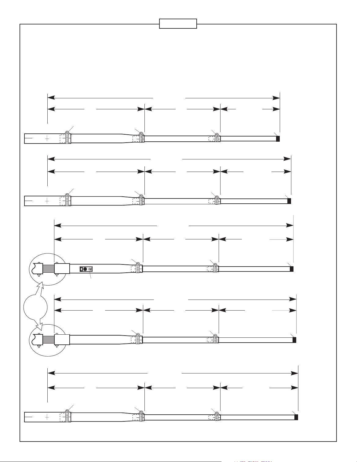
2 - Element Assembly
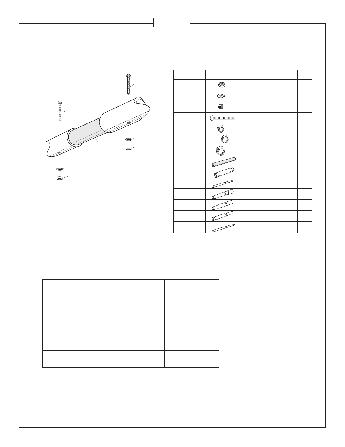
Figures 2A and 2B show the steps required for element assembly. Slide EC sections over fiberglass insulator (565)
until #8 screw holes line up (Figure 2B) . Insert screws (123) through holes and secure with lock washer (41) and nut
(11). Pay close attention to all dimensions shown. Use Chart A to determine your final element lengths for the frequency
you desire. (28-28.7 MHz or 28.7-29.7 MHz)
Figure 2A
Dimension E
EA
EA
410
410
36”
(91.4 cm)
36”
(91.4 cm)
36”
(91.4 cm)
26
EC
ED
ED
409
409
409
(81.3 cm)
EE
Dimension D
(81.3 cm)
EE
Dimension C
(81.3 cm)
EE
32”
32”
32”
407
407
407
Dimension
E1
EB
Dimension
D1
EB
Dimension
C1
EB
77
Element
#5
77
77
Element
#4
Element
#3
See
Figure
2B
EA
410
36”
(91.4 cm)
36”
(91.4 cm)
EC
ED
409
409
Dimension B
(81.3 cm)
EE
Dimension A
(81.3 cm)
EE
5
32”
32”
407
407
Dimension
B1
EB
Dimension
A1
EF
77
77
Element
#2
Element
#1
Page 7
Element Assembly Continued
123
123
41
41
565
11
Figure 2B
11
XM510
ID Part # Description Dimensions Qty
11 010011 SS Nut #8-32 4
41 011941 SS Lock #8 4
77 050077 Black 3/8’ 10
123 010123 SS Machine #8-32 x 1.5” 4
407 030407 Worm 5/8” 10
409 030409 Worm 11/16” 10
410 030410 Worm 1” 6
565 124565 Fiberglass 5/8” x 8” 2
EA XM510EA Aluminum 7/8” x 12” 3
EB XM510EB Aluminum 3/8” x 42” 8
EC XM510EC Aluminum 3/4 x 36” 4
ED X79ED Aluminum 3/4” x 36” 6
EE X79EE Aluminum 1/2” x 36” 10
EF X79EF Aluminum 3/8” x 48” 2
Washer
Plastic Cap (0.9 cm)
Screw (3.8 cm)
Clamp (1.6 cm)
Clamp (1.7 cm)
Clamp (2.5 cm)
Insulator (1.6 x 20.3 cm)
Tube (2.2 x 30.5 cm)
Tube (.9 x 106.7)
Tube (1.9 x 91.4 cm)
Tube (1.9 x 91.4 cm)
Tube (1.3 x 91.4 cm)
Tube (.4 x 121.9 cm)
ELEMENT #1
ELEMENT #2
ELEMENT #3
ELEMENT #4
ELEMENT #5
Chart A
DIMENSION 28-28.7 MHz 28.7-29.7 MHz
A
A1
B
B1
C
C1
D
D1
E
E1
110” (279.4 cm)
42” (106.7 cm)
102-1/2” (260.3 cm)
34-1/2 (87.6 cm)
99” (251.5 cm)
31” (78.7 cm)
101” (256.5 cm)
33” (83.8 cm)
96” (243.8 cm)
28” (71.1 cm)
106-1/2” (270.5 cm)
38-1/2” (97.8 cm)
99” (251.5 cm)
31” (78.7 cm)
95-1/2” (242.6 cm)
27-1/2” (69.8 cm)
97-1/2” (247.6 cm)
29-1/2” (74.9 cm)
90” (228.6 cm)
22” (55.9 cm)
6
Page 8
XM510
3 - Element to Boom Assembly
Element
#1
Figure 3B
Mark Center Line
of element using
element half lengths.
BA
Element
#2
Element
#3
BB
Element
#4
BC
495
Figure 3A
Element
#5
BD
Figure 3C
99
99
84
84
99
84
495
495
Figure 3D
Elements can be attached to the boom when the antenna is on
the ground or when the antenna is being installed on a tower.
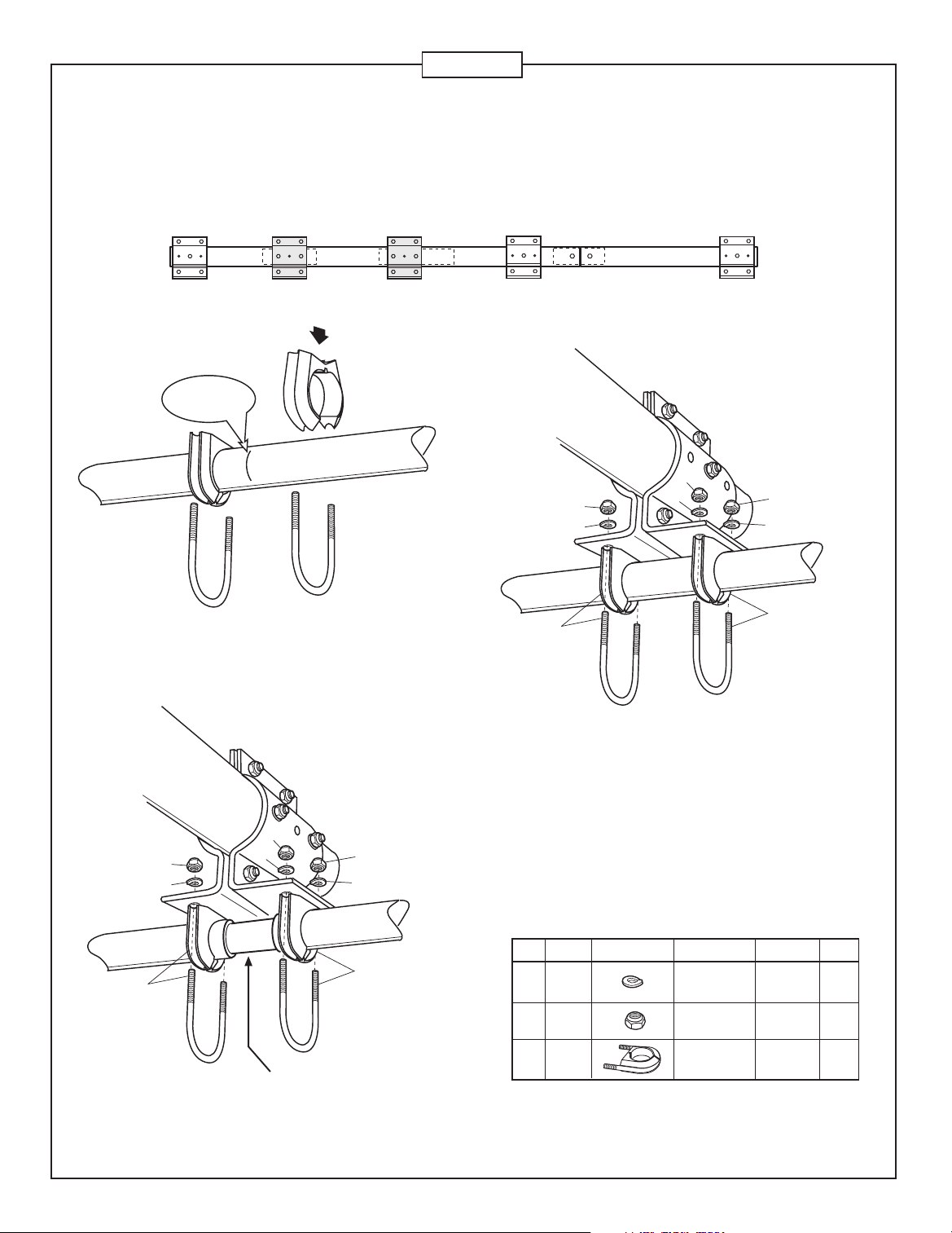
Refer to Figure 3A for element locations. Identify the hardware
required to secure the elements. Attach Cush-a-Clamps on each
element according to Figure 3B. When securing element to the
boom brackets, tighten each clamp until the element tubing can
99
99
84
84
FIBERGLASS
INSULATOR
99
84
495
no longer rotate inside the Cush-A-Clamp. The lock washers
under the nuts securing the Cush-A-Clamps should be tightened
until they are flat against the mounting bracket. Figure 3C
illustrates the mounting of elements 1, 4 and 5. Figure 3D shows
elements 2 and 3.
ID Part # Description Dimensions Qty
84 010084 SS Lock 1/4” 20
99 014399 SS Lock 1/4” 20
495 014495 Cush-a-Clamp® 7/8” 10
Washer (.6 cm)
Nut (.6 cm)
(2.2 cm)
7
Page 9
XM510
87
87
832
Element
#1
Element
Figure 4B
#2
FL
832
Element
#3
Figure 4A
Mast mounting
location for reference
Element
#4
Element
#5
4-Feed System Assembly
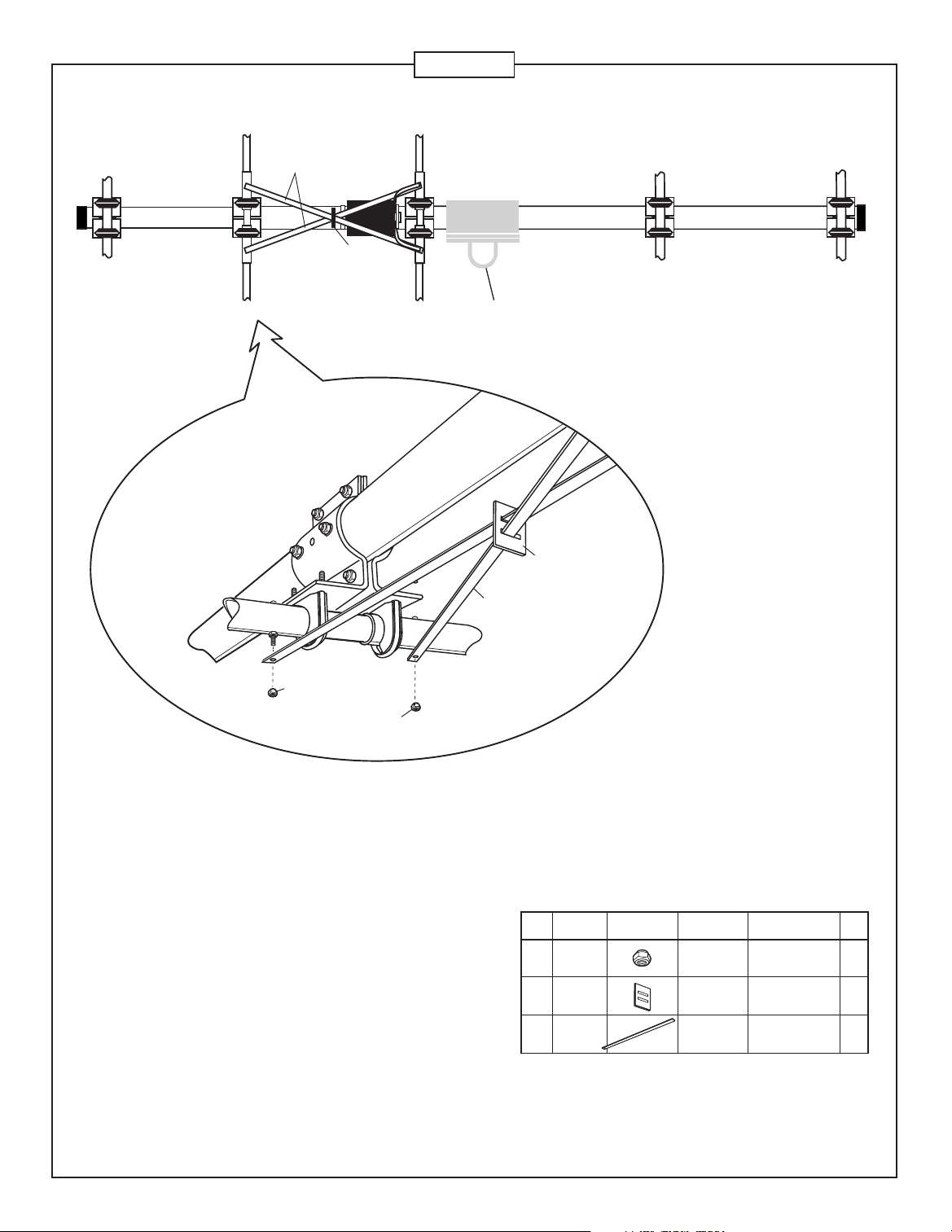
The feed system consists of 2 sub-assemblies. They are the feed-straps
(Figure 4B) and the matching network (Figure 4C).
Referring to Figure 4B, insert the feedline straps (FL) into the slots on the
strap insulator (832) . Attach the feedline straps to element #2 and secure
with nuts (87).
FL
ID Part # Description Dimensions Qty
87 014387 SS Lock #8-32 2
832 323832 Strap 2” x 1-1/2” x1/8” 1
FL XM510FL Aluminum 5/8” x 49-5/8” 2
Nut
Insulator (5.1 x 3.8 x .3 cm)
Strap (.9 x 126 c m)
8
Page 10
XM510
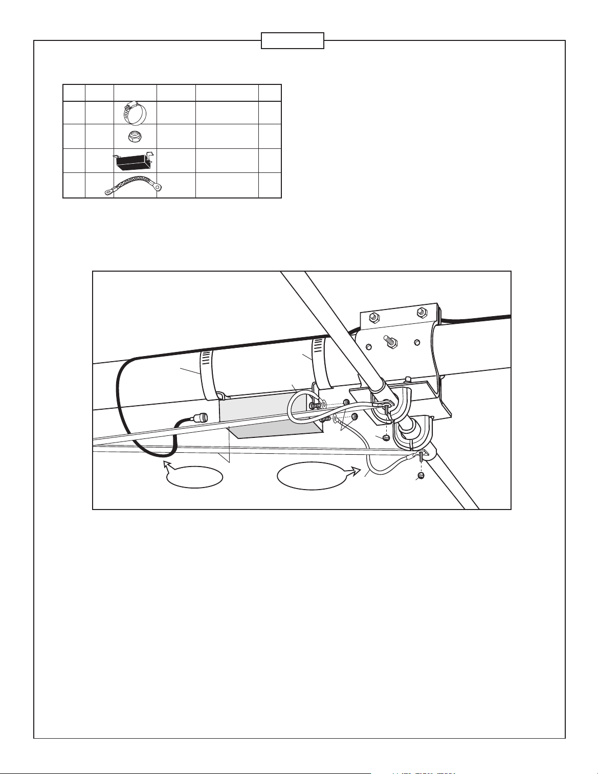
ID Part # Description Dimensions Qty
81 032881 Worm 2-1/16” x 3” 2
87 014387 SS Lock #8-32 4
MN MNXM Matching 1
FS X79FS Copper 1/2” x 6” 2
Clamp (5.2 x 7.6 cm)
Nut
Network
Braid (1.2 x 15 cm)
Figure 4C
81
4-Feed System Assembly
Continued
Reference Figure 4C for matching network mounting. Attach matching
network (MN) to boom with two worm clamps (81). Connect copper
braid feed straps (FS) from matching network terminals to aluminum
straps (FL) as shown. Form drip loops in the copper feed straps (FS)
and position them as shown.
81
FS
Coax Drip Loop
FL1
MN
Form Drip Loops
with feed straps.
87
87
Element #3
FS
87
9
Page 11
5- Boom to Mast Assembly
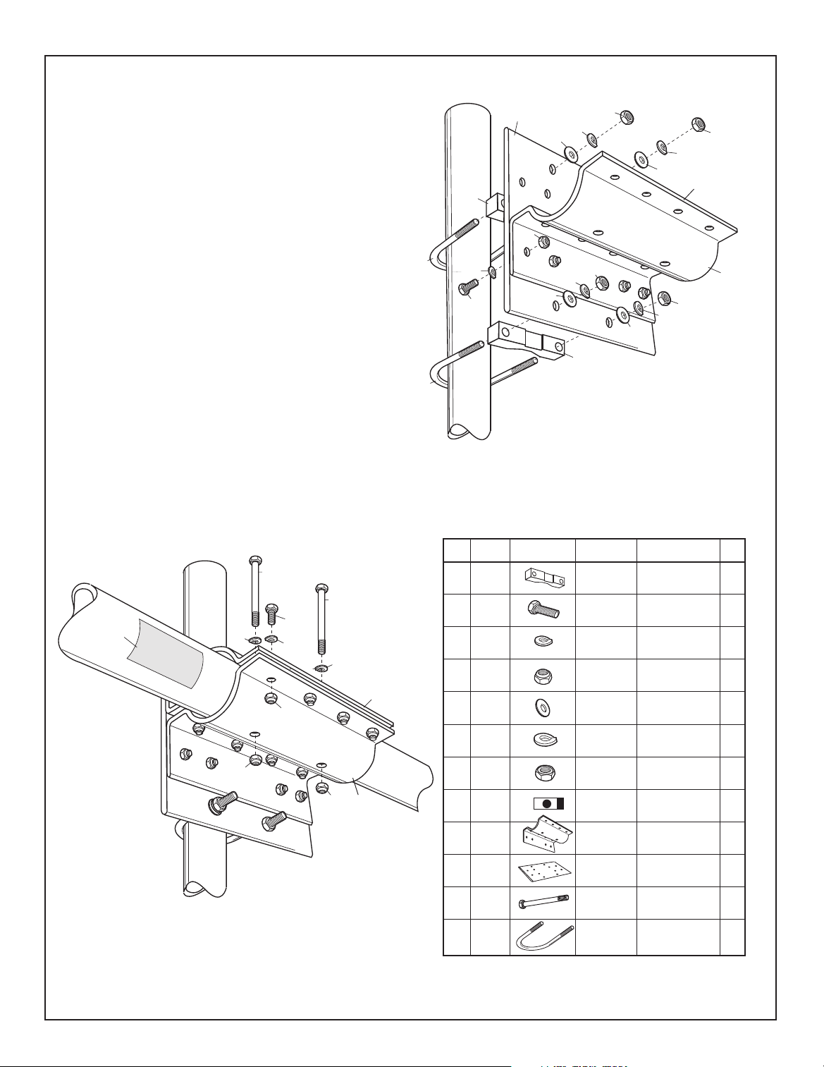
The XM510 boom to mast clamp is designed to be mounted on
the tower/mast so the built in boom shelf feature can be utilized.
Following this suggestion, if possible, will simplify antenna installation
Form the boom shelf by attaching the lower boom bracket (506)
to the mast plate (542) using hardware shown (Figure 5A). Attach
mast plate (542) to mast using U-bolts (3209) and V-blocks (35).
Place the boom on the boom shelf during installation. Loosely
attach the top boom bracket (506) to the mast-plate (542) and to
the lower boom bracket (506) as shown in Figure 5B. This allows
the boom to be moved back and forth for tower top element
mounting.
When all elements are securely mounted to the boom and the feed
system is in place, line up the 2 holes in the top of the upper boom
bracket (506) holes with the corresponding 2 holes in boom section
BC. Insert bolts (588) and tighten in place. Next, tighten the 8 bolts,
securing the upper and lower boom brackets. Tighten the 4 bolts
connecting the upper boom bracket to the mast plate.
Attach good quality coax with a PL-259 connector to the XM510
matching network. Form a drip-loop with the coax and secure the
coax to the boom. Insure PL-259 connector is waterproofed with
a good quality sealant after it is attached to the matching network.
3209
3209
208
208
209
209
208
207
Boom Shelf
209
209
208
207
35
506
542
207
35
99
84
82
207
Figure 4C
326
588
82
84
99
84
99
Figure 5B
588
99
ID Part # Description Dimensions Qty
35 170035 Aluminum 3-1/2” 2
82 010082 Hex 1/4-20 x 1” 16
84 010084 SS Lock 1/4” 18
84
506
99 014399 SS Lock 1/4” 18
207 010207 SS Flat 3/8” 4
208 010208 SS Lock 3/8” 4
209 010209 SS 3/8” 4
506
326 290326 Danger 1
506 324506 Aluminum 8” x 5-1/4” x 3/16” 2
542 194542 Alu Mounting 8” x 8” x 1/4” 1
588 014588 SS Hex 1/4” x 3-1/2” 2
3209 013209 U-Bolt 2-7/8” 2
V-Block (8.9 cm)
Bolt (2.5 cm)
Washer (0.6 cm)
Nut (.6 cm)
Washer (.95 cm)
Washer (.95 cm)
Nut (.95 cm)
Label
Bracket (20.3 x 13.3 x .5 cm)
Plate 20.3 x 20.3 x .6 cm)
Bolt (.6 x 8.9 cm)
(7.3 cm)
10
Page 12
XM510
SPECIFICATIONS
Frequency Coverage (Meters) 10
Total number of Elements 5
Free Space Gain (dBi) 9.3
Maximum Front to Back Ratio (dB) 30
VSWR Minimum 1.1:1
VSWR 1.5:1 Bandwidth (KHz) 750
2:1 Bandwidth (KHz) 1200
Longest Element, ft (m) 18.3 (5.6)
Turning Radius, ft (m) 13.0 (4.0)
The Electrical Specifications for all Cushcraft Amateur Antennas are derived from numerical
analysis and measured data taken on our test range. Performance may vary due to the random
variables associated with a specific application or installation.
Limited Warranty
Cushcraft Corporation, 48 Perimeter Road, Manchester, New Hampshire 03103,
warrants to the original consumer purchaser for one year from date of purchase
that each Cushcraft antenna is free of defects in material or workmanship. If, in
the judgement of Cushcraft, any such antenna is defective, then Cushcraft will,
at its option, repair or replace the antenna at its expense within thirty days of the
date the antenna is returned (at purchaser's expense) to Cushcraft or one of its
authorized representatives. This warranty is in lieu of all other expressed
warranties. Any implied warranty is limited in duration to one year.
Cushcraft Corporation shall not be liable for any incidental or consequential
damages which may result from a defect. Some states do not allow a limitation
on how long an implied warranty lasts or exclusions or limitations of incidental
or consequential damages, so the above limitation and exclusion may not apply
to you. This warranty gives you specific legal rights, and you may also have
other rights which vary from state to state. This warranty does not extend to any
products which have been subject to misuse, neglect, accident or improper
installation. Any repairs or alterations outside of the Cushcraft factory will nullify
this warranty.
Boom Length, ft (m) 19 (5.8)
Boom Diameter, in (cm) 2.5 (6.35)
Maximum Mast Diameter OD, in (cm) 2.5 (6.35)
Maximum Wind Survival, mph (kph) >100 (>161)
Maximum Wind Surface Area, ft
2
(m2) 3.4 (.32)
Wind Load @ 80 mph, lb (kg) 85 (38.7)
Maximum Power Handling (KW) 2
Weight, lb. (kg) 38 (17.3)
Design Safety Factor 1.25
SPECIFICATIONS SUBJECT TO CHANGE WITHOUT NOTICE.
COMMUNICATIONS ANTENNAS
48 Perimeter Road, Manchester NH 03103 USA • Telephone: 603-627-7877 • Fax: 603-627-1764 • E-mail: [email protected]
Web Site: http://www.cushcraft.com • International - Tel: +1-603-627-7877 • Fax:+1-603-627-1764
 Loading...