

Page 1

smartCUE Interfaces
User Manual
07.03.2013
Page 2

Contents
2 Contents
3 Introduction
3 Overview
3 Common Features
3 Models
3 Available Accessories
3 Programming
Box Contents
4
5 Specifications
5 Wired Models
6 Wireless Models
Mounting
7
7 Shelf Placement or Stacking
7 Rack Mounting
System And Power Connection
8
8 Wired Models
9 Wireless Models
Factory Default
10
10 Configuration
10 Restoring
Wired Models
18
18 smartCUE-zero
19 smartCUE-one
20 smartCUE-two
21 smartCUE-three
Wireless Models
22
22 smartCUE-zero-wifi
23 smartCUE-one-wifi
24 smartCUE-two-wifi
25 smartCUE-three-wifi
Admin Web
26
26 Access Admin Web
26 Login
26 Logout
27 Configuration
29 Password
29 Reset
29 License
Software and Firmware License
30
31 Notes
Setup the Unit
11
11 Wired Models
11 Wireless Models
Control Ports
12
12 Overview
12 SERIAL
14 IR/SERIAL
15 DIGITAL I/O
16 GENERAL I/O
17 RELAY
UM049_01_smartCUE_Interfaces
07.03.2013
© CUE, a.s. | Praha, Czech Republic 1990 - 2013
All rights reserved. | Specifications are subject to change without prior notice.
Page 3
smartCUE Interfaces | User Manual | Introduction
Introduction
Overview
Ultra-compact interfaces smartCUE allow to control devices from a controller or touch panel over a wired
or wireless network. Using these units the number of control ports can be cost-effectively expanded.
Additionally they simplify control to equipment located extended distances from a controller.
Common Features
▪ Ultra-compact interfaces for cost-effective control port expanding
▪ Wired models - 10/100 BaseT LAN communication with Power over Ethernet (PoE) power supply
▪ Wireless models - IEEE 802.11b/g Wi-Fi 2.4 GHz and power supply 12 to 24 VDC
▪ Control ports
▪ Bi-directional serial RS-232
▪ Bi-directional serial RS-232/422/485
▪ IR /serial outputs
▪ Digital I/Os
▪ General I/Os
▪ Relays NO-C-NC 24 V
▪ Front panel indicators for power, network and all control ports
▪ Web server and Admin Web for setup through a standard web browser
▪ Programming in Cue Visual Composer
▪ Fully compatible with touch panels, controllers and mobile solution runtimes
▪ Unied aluminium enclosure design for desktop, 19” rack rack, DIN rail and wall installation
Models
Model Product Code Description
smartCUE-zero CS0421 Interface with wired Ethernet, 2x serial, 4x digital I/O
smartCUE-one CS0440 Interface with wired Ethernet, 1x serial, 8x digital I/O
smartCUE-two CS0442 Interface with wired Ethernet, 1x serial, 8x digital I/O, 6x relay
smartCUE-three CS0444 Interface with wired Ethernet, 1x serial, 4x IR/serial, 8x digital I/O, 4x general I/O
smartCUE-zero-wi CS0423 Interface with Wi-Fi, 2x serial, 4x digital I/O
smartCUE-one-wi CS0441 Interface with Wi-Fi, 1x serial, 8x digital I/O
smartCUE-two-wi CS0443 Interface with Wi-Fi, 1x serial, 8x digital I/O, 6x relay
smartCUE-three-wi CS0445 Interface with Wi-Fi, 1x serial, 4x IR/serial, 8x digital I/O, 4x general I/O
Available Accessories
Model Product Code Description
PoE Adapter CS0327 PoE injector IEEE 802.3af compliant
Rack Mounting Shelf CS0449 Rack mounting kit for up to 4 interfaces
IR Adapter /i CS0256 Infra-red emitter
Opto-Input Adapter /i CS0257 Photosensitive cell sensor
IR Sprayer CS0295 IR control signal emitter
Serial IO Cable DTE /i CA0181 RS-232 serial cable DTE
Serial IO Cable DCE /i CA0182 RS-232 serial cable DCE
Cable RS-485 to PEbus CA0183 RS-485 cable between interface and switching units, dimmers, interfaces
Programming
All interfaces smartCUE have to be programmed using Cue Visual Composer.
© CUE, a.s. All Rights Reserved. | www.cuesystem.com | support@cuesystem.com
3
Page 4

Box Contents
Product Name
smartCUE Interfaces | User Manual | Box Contents
smartCUE-zero
Product Code CS0421 CS0440 CS0442 CS0444 CS0423 CS0441 CS0443 CS0445
Interface smartCUE-zero 1
Interface smartCUE-one 1
Interface smartCUE-two 1
Interface smartCUE-three 1
Interface smartCUE-zero-wi 1
Interface smartCUE-one-wi 1
Interface smartCUE-two-wi 1
Interface smartCUE-three-wi 1
Wi-Fi antenna 1 1 1 1
Connector set 1 1 1 1 1 1 1 1
IR Adapter /i 2 2
Ethernet cable straight-through 1 1 1 1
Power supply 1 1 1 1
Rubber feet 4 4 4 4 4 4 4 4
CE declaration 1 1 1 1 1 1 1 1
RoHS declaration 1 1 1 1 1 1 1 1
Data Sheet 1 1 1 1 1 1 1 1
Cue System Connector Wiring Sheet 1 1 1 1 1 1 1 1
smartCUE-one
smartCUE-two
smartCUE-three
smartCUE-zero-wi
smartCUE-one-wi
smartCUE-two-wi
smartCUE-three-wi
© CUE, a.s. All Rights Reserved. | www.cuesystem.com | support@cuesystem.com
4
Page 5
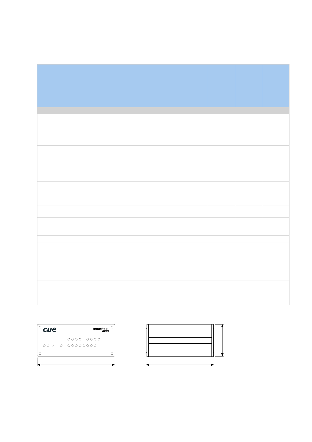
Specications
Wired Models
Product Name
smartCUE Interfaces | User Manual | Specifications
smartCUE-zero
smartCUE-one
smartCUE-two
smartCUE-three
Product Code CS0421 CS0440 CS0442 CS0444
Wired 10/100 BaseT Ethernet, RJ-45 connector 1
Bi-directional serial RS-232, baud rate 300 - 460 800 Bd,
5-pin 3.5 mm connector for each port
Bi-directional serial RS-232/422/485, baud rate 300 - 460 800 Bd,
5-pin 3.5 mm connector for each port
IR / Serial output, serial mode baud rate 1 200 - 115 200 Bd,
2-pin 3.5 mm connector for each port
1 - - -
- - - 4
1
Digital I/O can be congured as
• Digital input
• Digital open collector output max. 80 mA
4 8 8 8
5-pin 3.5 mm common connector with common ground
General I/O can be congured as
• Analog input 0 – 20 V
• Digital open collector output max. 80 mA
- - - 4
2-pin 3.5 mm connector for each port
Relay NO-C-NC, 24 V, max. 0.5 A,
3-pin 3.5 mm connector for each relay
- - 6 -
LED indicators Power,
network link, network activity,
control ports
Button Factory Default 1
Software Admin Web
Power supply Power over Ethernet
IEEE 802.3af Class 1 compatible
Enclosure Aluminium
Dimensions 105 x 43.5 x 92 mm / 4.14” x 1.7” x 3.6”
1/4 rack space, 1 U
Weight 0.3 kg
Environment conditions Operating temperature 10° to 40° C
Storage temperature 0° to 60° C
Relative humidity 10% to 90% non-condensing
Mechanical
IR/SERIAL
1 2 3 4
PWR
LINK
F. D .
1 1 2 3 4 5 6 7 8
SERIAL DIGITAL I/O
105 mm
© CUE, a.s. All Rights Reserved. | www.cuesystem.com | support@cuesystem.com
GENERAL I/O
1 2 3 4
92 mm
43.5 mm
5
Page 6
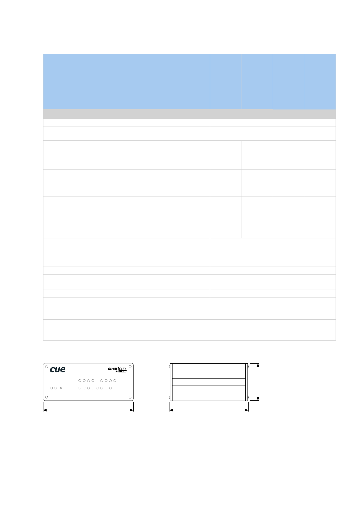
Wireless Models
Product Name
smartCUE Interfaces | User Manual | Specifications
smartCUE-zero-wi
smartCUE-one-wi
smartCUE-two-wi
smartCUE-three-wi
Product Code CS0423 CS0441 CS0443 CS0445
Wired 10/100 BaseT Ethernet, RJ-45 connector 1
Bi-directional serial RS-232, baud rate 300 - 460 800 Bd,
5-pin 3.5 mm connector for each port
Bi-directional serial RS-232/422/485, baud rate 300 - 460 800 Bd,
5-pin 3.5 mm connector for each port
IR / Serial output, serial mode baud rate 1 200 - 115 200 Bd,
2-pin 3.5 mm connector for each port
1
1
4
Digital I/O can be congured as
• Digital input
• Digital open collector output max. 80 mA
4 8 8 8
5-pin 3.5 mm common connector with common ground
General I/O can be congured as
• Analog input 0 – 20 V
• Digital open collector output max. 80 mA
- - 4
2-pin 3.5 mm connector for each port
Relay NO-C-NC, 24 V, max. 0.5 A,
3-pin 3.5 mm connector for each relay
- - 6 -
LED indicators Power,
network connection, network activity,
control ports
Button Factory Default 1
Software Admin Web
Power supply, power jack connector 12 - 24 VDC (+/-20%)
Power consumption Max. 3 W
Enclosure Aluminium
Dimensions 105 x 43.5 x 92 mm / 4.14” x 1.7” x 3.6”
1/4 rack space, 1 U
Weight 0.3 kg
Environment conditions Operating temperature 10° to 40° C
Storage temperature 0° to 60° C
Relative humidity 10% to 90% non-condensing
Mechanical
IR/SERIAL
1 2 3 4
PWR
WLAN
F. D .
1 1 2 3 4 5 6 7 8
SERIAL DIGITAL I/O
105 mm
© CUE, a.s. All Rights Reserved. | www.cuesystem.com | support@cuesystem.com
GENERAL I/O
1 2 3 4
92 mm
43.5 mm
6
Page 7
smartCUE Interfaces | User Manual | Mounting
Mounting
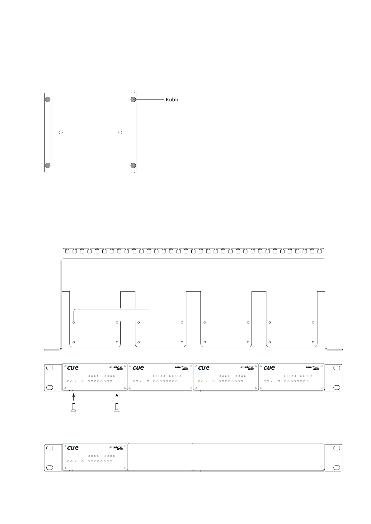
Shelf Placement or Stacking
Four rubber feet are provided for shelf placement or stacking. Stick the rubber feet near the corner edges on
the bottom side of smartCUE - see picture below.
Rubber feet
Rack Mounting
The Rack Mounting Shelf (CS0449) provides simple solution for installing interfaces to the 19” rack. It allows
to install up to four quarter-rack sized interfaces to single 19” unit rack space. All necessary accessories are
supplied with the shelf.
Interface is fixed to the Rack Mounting Shelf by two screws M3 x 6 using threads on the bottom side of
interface. Screws M3 x 6 are bundled to Rack Mounting Shelf. Don’t use longer screws to avoid damage of
PCBs inside the unit.
Screw holes
IR/SERIAL
PWR
LINK
F. D.
1 2 3 4
1 1 2 3 4 5 6 7 8
SERIAL DIGITAL I/O
GENERAL I/O
1 2 3 4
PWR
LINK
F. D.
IR/SERIAL
1 2 3 4
1 1 2 3 4 5 6 7 8
SERIAL DIGITAL I/O
GENERAL I/O
1 2 3 4
PWR
LINK
F. D.
IR/SERIAL
1 2 3 4
1 1 2 3 4 5 6 7 8
SERIAL DIGITAL I/O
GENERAL I/O
1 2 3 4
PWR
LINK
F. D.
1 1 2 3 4 5 6 7 8
SERIAL DIGITAL I/O
IR/SERIAL
1 2 3 4
GENERAL I/O
1 2 3 4
Screws M3 x 6
If you install less than four interfaces use cover panels delivered with the shelf to cover empty positions.
Cover panel 1/2
PWR
LINK
F. D.
IR/SERIAL
1 2 3 4
1 1 2 3 4 5 6 7 8
SERIAL DIGITAL I/O
GENERAL I/O
1 2 3 4
Cover panel 1/4
© CUE, a.s. All Rights Reserved. | www.cuesystem.com | support@cuesystem.com
7
Page 8
smartCUE Interfaces | User Manual | System And Power Connection
System And Power Connection
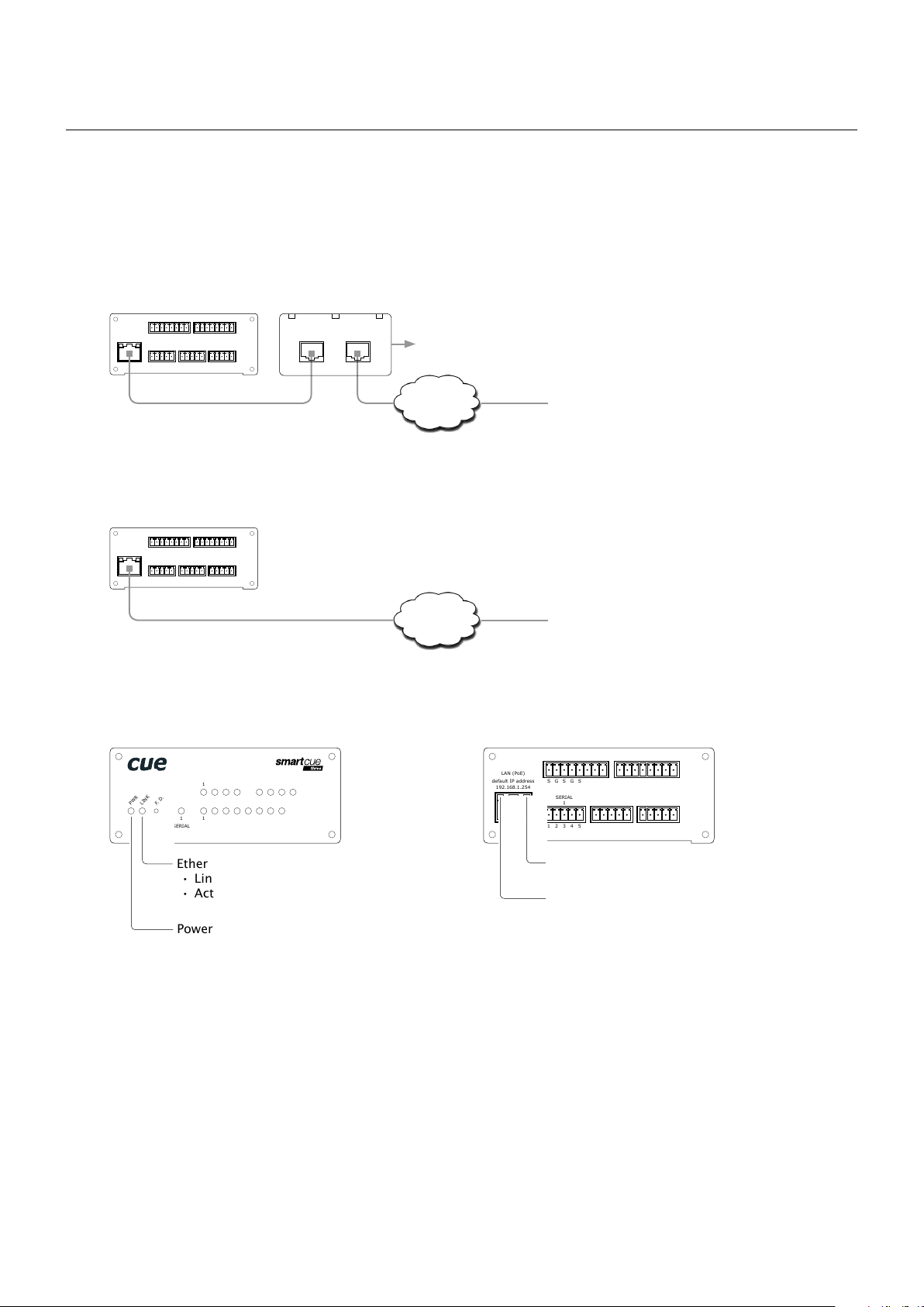
Wired Models
All wired interfaces are connected using 10/100 BaseT LAN communication and Power over Ethernet (PoE)
power supply.
For networks without PoE infrastructure it is necessary to use PoE Adapter compliant with IEEE802.3af
standard. PoE adapter isn’t part of interface delivery. Recommended model is Cue’s PoE Adapter PSA16U,
product code CS0327.
PoE Adapter
OUT IN
Touch panels and controllers
Power supply
Ethernet
LAN (PoE)
default IP address
192.168.1.254
IR/SERIAL
1 2 3 4
S G S G S G S G
SERIAL DIGITAL I/O
1 1 2 3 4 G
1 2 3 4 5
S S S S G
Ethernet cable
GENERAL I/O
1 2 3 4
S G S G S G S G
5 6 7 8 G
S S S S G
Following picture describes connection for network equipped with PoE IEEE802.3af infrastructure.
IR/SERIAL
LAN (PoE)
default IP address
192.168.1.254
1 2 3 4
S G S G S G S G
SERIAL DIGITAL I/O
1 2 3 4 5
GENERAL I/O
1 2 3 4
S G S G S G S G
S S S S G
5 6 7 8 G
S S S S G
1 1 2 3 4 G
Ethernet cable
Touch panels and controllers
Ethernet
with PoE
Following picture describes power and network indicators common for all wired models.
PWR
LINK
F. D .
IR/SERIAL
1 2 3 4
1 1 2 3 4 5 6 7 8
SERIAL DIGITAL I/O
GENERAL I/O
1 2 3 4
LAN (PoE)
default IP address
192.168.1.254
IR/SERIAL
1 2 3 4
S G S G S G S G
SERIAL DIGITAL I/O
1 1 2 3 4 G
1 2 3 4 5
S S S S G
GENERAL I/O
1 2 3 4
S G S G S G S G
5 6 7 8 G
S S S S G
Ethernet green indicator
• Link
• Activity (active = no light)
Power blue indicator
© CUE, a.s. All Rights Reserved. | www.cuesystem.com | support@cuesystem.com
Ethernet link green indicator
Ethernet activity yellow indicator
8
Page 9
smartCUE Interfaces | User Manual | System And Power Connection
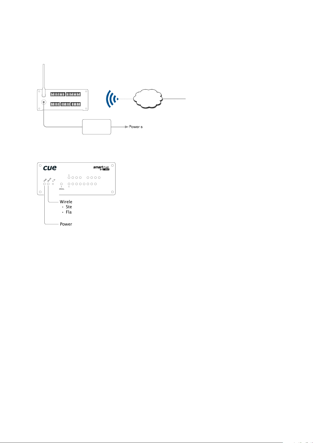
Wireless Models
All wireless models use Wi-Fi network, IEEE 802.11b/g Wi-Fi 2.4 GHz. Power supply is 12 to 24 VDC and it is
strictly recommended to use delivered CUEadapter.
Touch panels and controllers
Wi-Fi
Ethernet
Power supply
Default SSID: smartCUE
12 ~ 24 VDC
ANT
PWR IN
IR/SERIAL
1 2 3 4
S G S G S G S G
1 2 3 4 5
1 2 3 4
S G S G S G S G
DIGITAL I/O
SERIAL
1 2 3 4 G
1
S S S S G
12 ÷ 24 VDC
GENERAL I/O
5 6 7 8 G
S S S S G
CUEadapter
Following picture describes power and network indicators common for all wireless models.
IR/SERIAL
1 2 3 4
PWR
WLAN
F. D .
1 1 2 3 4 5 6 7 8
SERIAL DIGITAL I/O
Wireless network green indicator
• Steady light - connected
• Flashing light - connecting
Power blue indicator
GENERAL I/O
1 2 3 4
© CUE, a.s. All Rights Reserved. | www.cuesystem.com | support@cuesystem.com
9
Page 10
Factory Default
Conguration
Every device shipped from the factory is set according to this table.
Conguration Identication Name Empty Empty
Network IP address 192.168.1.254 192.168.1.254
Subnet mask 255.255.255.0 255.255.255.0
Default gateway 192.168.1.1 192.168.1.1
Admin Web port 80 80
TCP port 1 10001 10001
TCP port 2
UDP port 7777 7777
WiFi Network name (SSID) - smartCUE
Network type - Ad-Hoc
Channel (Ad-Hoc only) - 9
Security type - None
Encryption type - None
Security key - Empty
Password Empty (no input required) Empty (no input required)
(1)
smartCUE Interfaces | User Manual | Factory Default
Wired Models Wireless Models
10002 10002
(1)
Only for smartCUE-zero, smartCUE-zero-wifi, smartCUE-three, smartCUE-three-wifi
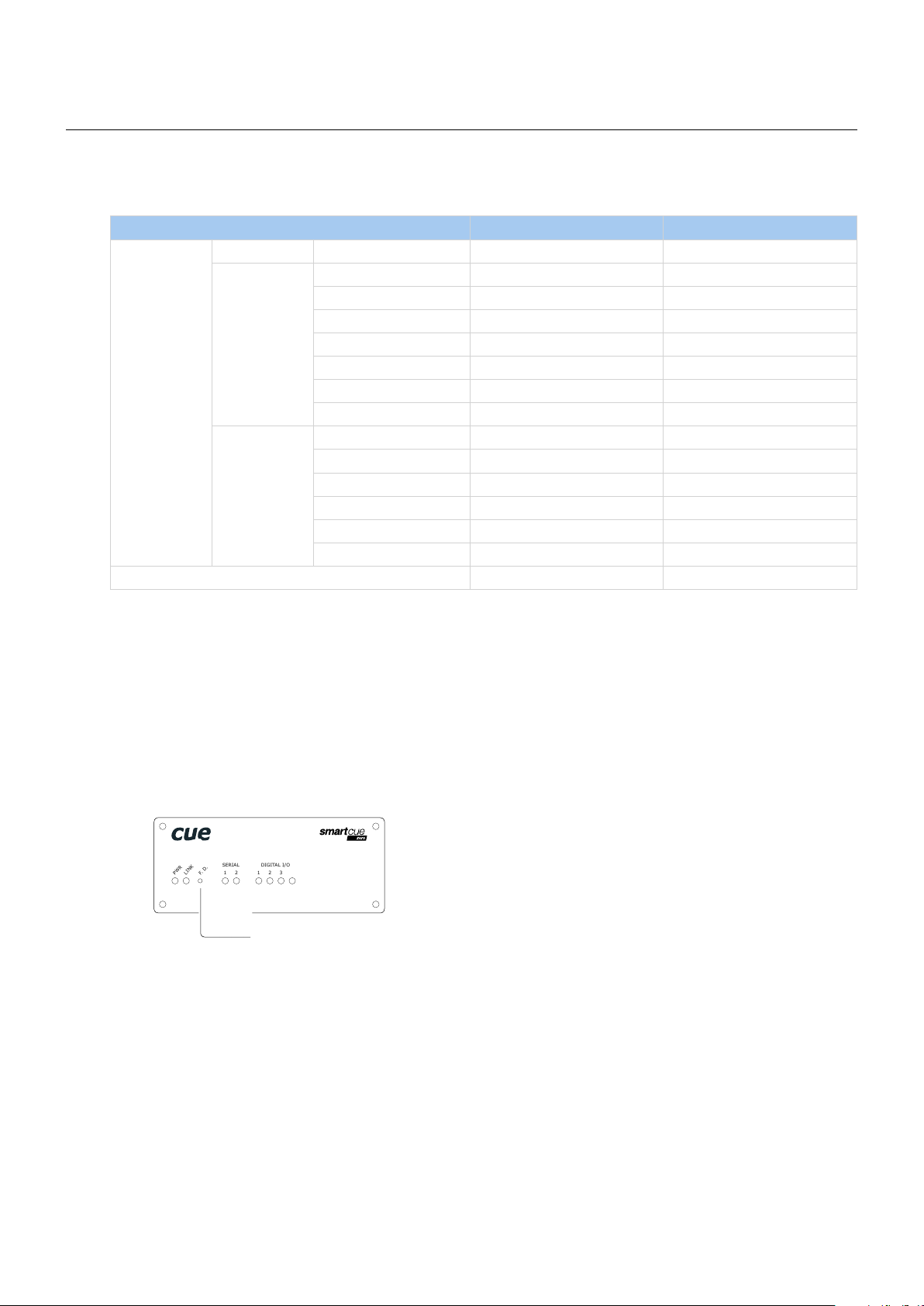
Restoring
The main purpose of this functionality is to regain connection with lost password or unknown IP settings.
To restore the factory default configuration, provide following steps
1. Turn the power off. Disconnect Ethernet cable for wired models or power adapter for wireless models.
2. Press button F.D. located on the front panel and hold it.
SERIAL
DIGITAL I/O
1 2
PWR
LINK
F. D .
3. Turn the power on and hold button F.D. at least 7 seconds.
4. Factory default configuration is restored according table above.
1 2 3 4
Button factory default
© CUE, a.s. All Rights Reserved. | www.cuesystem.com | support@cuesystem.com
10
Page 11

Setup the Unit
Wired Models
To get access to the factory default configured unit provide following steps
1. Set manually PC Local Area Connection (Ethernet network adapter) to
▪ IP address: 192.168.1.x where x = 1 to 253
▪ Subnet mask: 255.255.255.0
2. Connect the interface to PC. Use crossover cable for direct connection between PC and smartCUE if
your PC ethernet adapter doesn’t support auto-sense.
3. Use standard Internet browser and ll address line with http://192.168.1.254.
4. Provide setup using Admin Web. Use section Conguration / Network to set smartCUE connection to
target network. Settings depends on the network, however typically it is necessary to set
▪ IP address
smartCUE Interfaces | User Manual | Setup the Unit
Wireless Models
The unit uses Ad-Hoc wireless mode for initial setup. To get access to the factory default configured unit
provide following steps
1. Set manually your PC wireless adapter to
▪ IP address: 192.168.1.x where x = 1 to 253
▪ Subnet mask: 255.255.255.0
2. Disable all other PC network adapters which are congured as IP address 192.168.1.x (DHCP or static).
3. Switch on the smartCUE.
4. Connect your PC to wireless network Name: smartCUE
5. Use standard Internet browser and ll address line with http://192.168.1.254.
6. Provide setup using Admin Web. Use section Conguration / Network and Conguration / WiFi to
set smartCUE connection to target network. Settings depends on the network, however typically it is
necessary to set
▪ IP address
▪ Network name (SSID)
▪ Network type: Infrastructure (important step)
▪ Security type
▪ Security key
© CUE, a.s. All Rights Reserved. | www.cuesystem.com | support@cuesystem.com
11
Page 12

smartCUE Interfaces | User Manual | Control Ports
Control Ports
Overview
This section describes control ports used in smartCUE interfaces. Specific port numbers and combinations are
described in the section Specifications and in sections describing specific models.
SERIAL
Bi-directional Serial RS-232
This bi-directional serial channels is used for RS-232 communication.
Output signal levels are in the -12 V to +12 V range.
Baud rate can be set to the following values: 300, 600, 1 200, 2 400, 4 800, 9 600, 19 200, 38 400, 57 600,
115 200, 230 400 and 460 800 Bd (bps).
Connector pin out
SERIAL RS-232
5-pin 3.5 mm Pin Signal Description Direction
1 TxD RS-232 Transmitted Data From interface
2 RTS RS-232 Request to Send From interface
1 2 3 4 5
3 GND Ground
4 RxD RS-232 Received Data To interface
5 CTS RS-232 Clear to Send To interface
© CUE, a.s. All Rights Reserved. | www.cuesystem.com | support@cuesystem.com
12
Page 13

smartCUE Interfaces | User Manual | Control Ports
Bi-directional Serial RS-232/422/485
Overview
These bi-directional serial channels are used for RS-232, RS-422 and RS-485 communication.
Baud rate can be set to the following values: 300, 600, 1 200, 2 400, 4 800, 9 600, 19 200, 38 400, 57 600,
115 200, 230 400 and 460 800 Bd (bps).
Default mode for all channels is RS-232, other modes must be set in programming application. For more
details see programming manuals.
RS-232 Mode
Output signal levels for RS-232 are in the -10 V to +10 V range. This is default mode for all channels.
Connector pin out
SERIAL RS-232
5-pin 3.5 mm Pin Signal Description Direction
1 TxD RS-232 Transmitted Data From interface
2 RTS RS-232 Request to Send From interface
1 2 3 4 5
3 GND Ground
4 RxD RS-232 Received Data To interface
5 CTS RS-232 Clear to Send To interface
RS-422 Mode
This mode must be set in the programming application.
Connector pin out
SERIAL RS-422
5-pin 3.5 mm Pin Signal Description Direction
1 Tx A+ RS-422 Transmit Data (Idles High) From interface
2 Tx B- RS-422 Transmit Data (Idles Low) From interface
1 2 3 4 5
3 GND Ground
4 Rx A+ RS-422 Receive Data (Idles High) To interface
5 Rx B- RS-422 Receive Data (Idles Low) To interface
RS-485 Mode
This mode must be set in the programming application.
Connector pin out
SERIAL RS-485
5-pin 3.5 mm Pin Signal Description
1 A+ RS-422 Transmit Data (Idles High)
2 B- RS-422 Transmit Data (Idles Low)
1 2 3 4 5
3 GND Ground
4 N.C. RS-422 Receive Data (Idles High)
5 N.C. RS-422 Receive Data (Idles Low)
© CUE, a.s. All Rights Reserved. | www.cuesystem.com | support@cuesystem.com
13
Page 14

smartCUE Interfaces | User Manual | Control Ports
IR/SERIAL
This type of port provides
▪ Output for infra-red emitters (IR Adapter /i, IR Sprayer)
▪ RS-232 serial output (one way). Output signal levels are in the -12 V to +12 V range and baud rate can
be set to the following values: 1 200, 2 400, 4 800, 9 600, 19 200, 38 400, 57 600, 115 200 Bd (bps).
The IR outputs and RS-232 outputs can be combined on independent outputs. For example two outputs can
be used as IR, two outputs can be used as RS-232.
Connector pin out
IR/SERIAL
2-pin 3.5 mm Pin Signal Description
S Signal IR/Serial Signal (Output)
S G
G GND Ground
Notes
▪ All pins labelled G are connected together.
▪ Up to three original infra-red emitters IR Adapter /i can be connected to each output in parallel.
▪ Up to ten IR Sprayers can be connected to each output in parallel
▪ It is not recommended to connect more infra-red emitters of various manufacturers in parallel because
the output can be either overloaded or damaged.
© CUE, a.s. All Rights Reserved. | www.cuesystem.com | support@cuesystem.com
14
Page 15

smartCUE Interfaces | User Manual | Control Ports
DIGITAL I/O
Digital I/O provide digital input as well as digital output. Each Digital I/O port can be used either as input or
as output.
Pull-up resistor 680 ohms is connected to +5 VDC. Digital input is rated 0 – 24 VDC, threshold is 2 V.
Voltage on I/O with open output transistor is approx. 4.3 VDC, because protection diode is connected in
series (0.7 V drop-down). Voltage on I/O for output switch on is approx. 0.6 V. Max. 24 VDC / 80 mA can be
switched by output transistor.
Schematic diagram
+5 VDC
680 Ohm
10 kOhm
INPUT
value CLOSE (< 2 V) / OPEN (> 2 V)
Input / Output
Common
OUTPUT
value CLOSE / OPEN
Connector pin out
5-pin 3.5 mm Pin Signal Description
1 2 3 4 G
S S GS S
S Signal Input / Output Signal 1 - 4, 5 - 8
G GND Common ground for all I/Os
DIGITAL I/O
© CUE, a.s. All Rights Reserved. | www.cuesystem.com | support@cuesystem.com
15
Page 16

smartCUE Interfaces | User Manual | Control Ports
GENERAL I/O
General I/O provides analog input as well as digital output. Each General I/O port can be used either as input
or as output.
Pull-up resistor 680 ohms is connected to +5 VDC and can be switched on and off for each I/O
independently. I/O voltage with pull-up on is approx. +4.3 VDC, because protection diode is connected in
series (0.7 V drop down). Analog input is rated 0 – 20 VDC.
Analog to digital (A/D) converter has 12-bits precision (i.e. 4096 levels). Digital output can switch max. 24
VDC / 80 mA. Output voltage for output switch on is approx. 0.6 V.
Schematic diagram
+5 VDC
ON OFF
PULLUP
value ON / OFF
A
680 Ohm
D
12 bit
Input / Output Signal
Ground
INPUT
OUTPUT
value CLOSE / OPEN
Connector pin out
5-pin 3.5 mm Pin Signal Description
1 2 3 4 G
S S GS S
S Signal Input / Output Signal 1 - 4
G GND Common ground for all I/Os
GENERAL I/O
© CUE, a.s. All Rights Reserved. | www.cuesystem.com | support@cuesystem.com
16
Page 17

smartCUE Interfaces | User Manual | Control Ports
RELAY
This port provides one isolated low voltage relay. Each relay contact closure is rated 24 V / 0.5 A.
Normally Close (NC) and Normally Open (NO) contacts as well as Common (C) contact of each relay can be
used. The Normally Close (NC) position is the state of the relay when it is not turned on (energized).
Relay open Relay close
NC
NC
C
NO
C
NO
Connector pin out
3-pin 3.5 mm Pin Description
NC Relay Contact Normal Close
C Relay Contact Common
C NO
NC
NO Relay Contact Normal Open
RELAY
© CUE, a.s. All Rights Reserved. | www.cuesystem.com | support@cuesystem.com
17
Page 18

smartCUE Interfaces | User Manual | Wired Models
Wired Models
smartCUE-zero
Overview
The wired interface equipped with 10/100 BaseT LAN communication and Power over Ethernet power supply.
It offers following control ports
▪ 1x Bi-directional serial port RS-232 (Serial 1)
▪ 1x Bi-directional serial port RS-232/422/485 (Serial 2)
▪ 4x Digital I/O
Front Panel
SERIAL
DIGITAL I/O
1 2
PWR
LINK
F. D .
1 2 3 4
Digital I/O 1 - 4 green indicators
Serial 2 green / red indicator
Serial 1 green / red indicator
Button factory default
Ethernet green indicator
• Link
• Activity (active = no light)
Power blue indicator
Rear Panel
LAN (PoE)
default IP address
192.168.1.254
SERIAL
1 2 3 4 5 S S S S G
1 2 3 4 5
DIGITAL I/O
1 2 3 4 G
21
Digital I/O 1 - 4, common gnd
Bi-directional serial port 2 RS-232/422/485
Bi-directional serial port 1 RS-232
Ethernet link green indicator
Ethernet with PoE
Ethernet activity yellow indicator
© CUE, a.s. All Rights Reserved. | www.cuesystem.com | support@cuesystem.com
18
Page 19

smartCUE Interfaces | User Manual | Wired Models
smartCUE-one
Overview
The wired interface equipped with 10/100 BaseT LAN communication and Power over Ethernet power supply.
It offers following control ports
▪ 1x Bi-directional serial port RS-232
▪ 8x Digital I/O
Front Panel
PWR
LINK
F. D .
Rear Panel
LAN (PoE)
default IP address
192.168.1.254
SERIAL
1
SERIAL
1
1 2 3 4 5
1 2 3 4
1 2 3 4 G
S S S S G
DIGITAL I/O
6 7 85
DIGITAL I/O
Digital I/O 1 - 8 green indicators
Serial 1 green / red indicator
Button factory default
Ethernet green indicator
• Link
• Activity (active = no light)
Power blue indicator
5 6 7 8 G
S S S S G
Digital I/O 5 - 8, common gnd
Digital I/O 1 - 4, common gnd
Bi-directional serial port 1 RS-232
Ethernet link green indicator
Ethernet with PoE
Ethernet activity yellow indicator
© CUE, a.s. All Rights Reserved. | www.cuesystem.com | support@cuesystem.com
19
Page 20

smartCUE Interfaces | User Manual | Wired Models
smartCUE-two
Overview
The wired interface equipped with 10/100 BaseT LAN communication and Power over Ethernet power supply.
It offers following control ports
▪ 1x Bi-directional serial port RS-232
▪ 8x Digital I/O
▪ 6x Low-voltage relay
Front Panel
Relay 1 - 6 red indicators
RELAY
1 2 3 4 5 6
PWR
LINK
F. D .
1 2 3 4 5 6 7 8
SERIAL
1
DIGITAL I/O
Digital I/O 1 - 8 green indicators
Serial 1 green / red indicator
Button factory default
Ethernet green indicator
• Link
• Activity (active = no light)
Power blue indicator
Rear Panel
LAN (PoE)
default IP address
192.168.1.254
Relay 1 - 6
1 432 65
NC C NO NC C NO NC C NO NC C NO NC C NONC C NO
SERIAL
RELAY
DIGITAL I/O
5 6 7 8 G1 2 3 4 G1
S S S S GS S S S G1 2 3 4 5
Digital I/O 5 - 8, common gnd
Digital I/O 1 - 4, common gnd
Bi-directional serial port 1 RS-232
Ethernet link green indicator
Ethernet with PoE
Ethernet activity yellow indicator
© CUE, a.s. All Rights Reserved. | www.cuesystem.com | support@cuesystem.com
20
Page 21

smartCUE Interfaces | User Manual | Wired Models
smartCUE-three
Overview
The wired interface equipped with 10/100 BaseT LAN communication and Power over Ethernet power supply.
It offers following control ports
▪ 1x Bi-directional serial port RS-232
▪ 4x IR/Serial output
▪ 8x Digital I/O
▪ 4x General I/O
Front Panel
IR/Serial 1 - 4 yellow indicators
General I/O 1 - 4 green indicators
PWR
LINK
F. D .
Rear Panel
LAN (PoE)
default IP address
192.168.1.254
IR/SERIAL
1 2 3 4
1 1 2 3 4 5 6 7 8
SERIAL DIGITAL I/O
IR/SERIAL
1 2 3 4
S G S G S G S G
SERIAL DIGITAL I/O
1 1 2 3 4 G
1 2 3 4 5
1 2 3 4
S G S G S G S G
S S S S G
GENERAL I/O
1 2 3 4
Digital I/O 1 - 8 green indicators
Serial 1 green / red indicator
Button factory default
Ethernet green indicator
• Link
• Activity (active = no light)
Power blue indicator
IR/Serial output 1 - 4
General I/O 1 - 4
GENERAL I/O
5 6 7 8 G
S S S S G
Digital I/O 5 - 8, common gnd
Digital I/O 1 - 4, common gnd
Bi-directional serial port 1 RS-232
Ethernet link green indicator
Ethernet with PoE
Ethernet activity yellow indicator
© CUE, a.s. All Rights Reserved. | www.cuesystem.com | support@cuesystem.com
21
Page 22

smartCUE Interfaces | User Manual | Wireless Models
Wireless Models
smartCUE-zero-wi
Overview
The wireless interface equipped with Wi-Fi network, IEEE 802.11b/g Wi-Fi 2.4 GHz. Power supply 12 - 24 VDC.
It offers following control ports
▪ 1x Bi-directional serial port RS-232 (Serial 1)
▪ 1x Bi-directional serial port RS-232/422/485 (Serial 2)
▪ 4x Digital I/O
Front Panel
SERIAL
DIGITAL I/O
1 2
PWR
WLAN
F. D .
1 2 3 4
Digital I/O 1 - 4 green indicators
Serial 2 green / red indicator
Serial 1 green / red indicator
Button factory default
Wireless network green indicator
• Steady light - connected
• Flashing light - connecting
Power blue indicator
Rear Panel
ANT
Default SSID: smartCUE
PWR IN
12 ~ 24 VDC
SERIAL
1
1 2 3 4 5 S S S S G
1 2 3 4 5
DIGITAL I/O
2
1 2 3 4 G
Antenna connector
Digital I/O 1 - 4, common gnd
Bi-directional serial port 2 RS-232/422/485
Bi-directional serial port 1 RS-232
Power supply 12 - 24 VDC
© CUE, a.s. All Rights Reserved. | www.cuesystem.com | support@cuesystem.com
22
Page 23

smartCUE Interfaces | User Manual | Wireless Models
smartCUE-one-wi
Overview
The wireless interface equipped with Wi-Fi network, IEEE 802.11b/g Wi-Fi 2.4 GHz. Power supply 12 - 24 VDC.
It offers following control ports
▪ 1x Bi-directional serial port RS-232
▪ 8x Digital I/O
Front Panel
PWR
WLAN
F. D .
Rear Panel
ANT
Default SSID: smartCUE
PWR IN
12 ~ 24 VDC
SERIAL
1
SERIAL
1
1 2 3 4 5
1 2 3 4
1 2 3 4 G
S S S S G
DIGITAL I/O
6 7 85
DIGITAL I/O
Digital I/O 1 - 8 green indicators
Serial 1 green / red indicator
Button factory default
Wireless network green indicator
• Steady light - connected
• Flashing light - connecting
Power blue indicator
Antenna connector
5 6 7 8 G
S S S S G
Digital I/O 5 - 8, common gnd
Digital I/O 1 - 4, common gnd
Bi-directional serial port 1 RS-232
Power supply 12 - 24 VDC
© CUE, a.s. All Rights Reserved. | www.cuesystem.com | support@cuesystem.com
23
Page 24

smartCUE Interfaces | User Manual | Wireless Models
smartCUE-two-wi
The wireless interface equipped with Wi-Fi network, IEEE 802.11b/g Wi-Fi 2.4 GHz. Power supply 12 - 24 VDC.
It offers following control ports
▪ 1x Bi-directional serial port RS-232
▪ 8x Digital I/O
▪ 6x Low-voltage relay
Front Panel
Relay 1 - 6 red indicators
RELAY
1 2 3 4 5 6
PWR
WLAN
F. D .
1
1 2 3 4 5 6 7 8
SERIAL DIGITAL I/O
Digital I/O 1 - 8 green indicators
Serial 1 green / red indicator
Button factory default
Wireless network green indicator
• Steady light - connected
• Flashing light - connecting
Power blue indicator
Rear Panel
ANT
Default SSID: smartCUE
PWR IN
12 ~ 24 VDC
Antenna connector
Relay 1 - 6
1 432 65
NC C NO NC C NO NC C NO NC C NO NC C NONC C NO
SERIAL
RELAY
DIGITAL I/O
5 6 7 8 G1 2 3 4 G1
S S S S GS S S S G1 2 3 4 5
Digital I/O 5 - 8, common gnd
Digital I/O 1 - 4, common gnd
Bi-directional serial port 1 RS-232
Power supply 12 - 24 VDC
© CUE, a.s. All Rights Reserved. | www.cuesystem.com | support@cuesystem.com
24
Page 25

smartCUE Interfaces | User Manual | Wireless Models
smartCUE-three-wi
The wireless interface equipped with Wi-Fi network, IEEE 802.11b/g Wi-Fi 2.4 GHz. Power supply 12 - 24 VDC.
It offers following control ports
▪ 1x Bi-directional serial port RS-232
▪ 4x IR/Serial output
▪ 8x Digital I/O
▪ 4x General I/O
Front Panel
IR/Serial 1 - 4 yellow indicators
General I/O 1 - 4 green indicators
PWR
WLAN
F. D .
Rear Panel
ANT
Default SSID: smartCUE
PWR IN
12 ~ 24 VDC
IR/SERIAL
1 2 3 4
1 1 2 3 4 5 6 7 8
SERIAL DIGITAL I/O
IR/SERIAL
1 2 3 4
S G S G S G S G
SERIAL
1
1 2 3 4 5
1 2 3 4 G
S S S S G
1 2 3 4
S G S G S G S G
DIGITAL I/O
GENERAL I/O
1 2 3 4
Digital I/O 1 - 8 green indicators
Serial 1 green / red indicator
Button factory default
Wireless network green indicator
• Steady light - connected
• Flashing light - connecting
Power blue indicator
Antenna connector
IR/Serial output 1 - 4
General I/O 1 - 4
GENERAL I/O
5 6 7 8 G
S S S S G
Digital I/O 5 - 8, common gnd
Digital I/O 1 - 4, common gnd
Bi-directional serial port 1 RS-232
Power supply 12 - 24 VDC
© CUE, a.s. All Rights Reserved. | www.cuesystem.com | support@cuesystem.com
25
Page 26

smartCUE Interfaces | User Manual | Admin Web
Admin Web
Access Admin Web
Run the Internet browser on your PC and type in the touch panel IP address. Factory default IP address is
192.168.1.254. The default password is empty.
Login
If password isn’t empty, you have to login at first for
operating with your interface via these web pages.
Enter your password into the Password box and click the
Login button to enter the interface web pages.
Remember that the password is case sensitive. For
changing your password use the Password menu after you
are logged in.
Logout
When you have finished working with the unit, click
Logout button to exit.
This screen isn’t displayed if password is empty (factory
default status).
© CUE, a.s. All Rights Reserved. | www.cuesystem.com | support@cuesystem.com
26
Page 27

Conguration
Identication
Network
smartCUE Interfaces | User Manual | Admin Web
Each interface can be identified by a unique identification
name. Unique names are most useful in applications
requiring more than one interfaces. This enables
programmers and installers to reference interface with
logical, user friendly names, like “boardroom”, “lobby”,
etc.
To set the interface identity, enter the unique name you
wish to use in the Name box.
Be sure to click the Apply button for any changes to
become effective!
This page is used for establishing the communication
parameters. All interfaces use standard internet protocol
(IP) communication parameters.
The following parameter is read-only.
▪ Physical address (MAC)
The parameters bellow can be set by the user.
▪ IP address
▪ Subnet mask
▪ Default gateway
▪ Admin Web port
▪ TCP port 1
▪ TCP port 2
▪ UDP port
Carefully note this addressing information (and any
changes you select to make to the IP address, subnet
mask, default gateway, ...). This information must be
entered into the Cue Visual Composer program written
for your specific application. For control systems with
more than one interface, a unique IP address must be
given to each smartCUE. In case you are using a router
don’t forget to open the appropriate TCP and UDP ports.
DHCP is not supported in this release.
Be sure to click the Apply button for any changes to
become effective!
© CUE, a.s. All Rights Reserved. | www.cuesystem.com | support@cuesystem.com
27
Page 28

WiFi
smartCUE Interfaces | User Manual | Admin Web
This section is applied for wireless models only.
Insert an Network name (SSID). It is the name of the
network you want to access. It is used to identify different
wireless networks. It is case-sensitive and must not
exceed 32 alphanumeric characters, which may be any
keyboard character.
Select Network type Infrastructure or Ad-Hoc.
Select from the list-box the radio channel for the Ad Hoc
network. Configurable only when Network Type is set to
Ad-Hoc. The default value is 9.
Select Security type
▪ None
▪ WEP (Wired Equivalent Privacy 64-bit/128-bit)
▪ WPA-Personal (Wi-Fi Protected Access)
▪ WPA2-Personal (Wi-Fi Protected Access IEEE 802.11i)
Select Encryption type.
▪ TKIP (Temporal Key Integrity Protocol)
▪ AES (Advanced Encryption Standard) sometimes
labeled as CCMP (Counter Cipher Mode with Block
Chaining Message Authentication Code Protocol)
Select Security key.
▪ A WEP key is one of the following:
- 5 case-sensitive characters
- 13 case-sensitive characters
- 10 case-insensitive characters using 0-9, A-F
- 26 case-insensitive characters using 0-9, A-F
▪ A WPA-Personal password must be one of the
following:
- 8~63 case-sensitive characters
- 64 case-insensitive characters using 0-9, A-F
▪ A WPA2-Personal password must be one of the
following:
- 8~63 case-sensitive characters
- 64 case-insensitive characters using 0-9, A-F
© CUE, a.s. All Rights Reserved. | www.cuesystem.com | support@cuesystem.com
28
Page 29

Password
Reset
smartCUE Interfaces | User Manual | Admin Web
A case sensitive password is necessary to login to the web
pages.
Set a new password via the New password box. You
must reenter the password in the Confirm new password
box (an error message will generate if the confirmation
does not match, in which case you should reenter your
password again in both boxes). Check Hide characters
check-box to keep your password secure.
Finally, the new password is implemented by clicking the
Apply button.
To restart your interface, click the Reset button.
License
This page describes software license.
© CUE, a.s. All Rights Reserved. | www.cuesystem.com | support@cuesystem.com
29
Page 30

smartCUE Interfaces | User Manual | Software and Firmware License
Software and Firmware License
END-USER NOTICE AND LICENSE AGREEMENT FROM CUE, a.s.
NOTICE TO END-USER: CAREFULLY READ THE FOLLOWING LEGAL AGREEMENT (THIS “LICENSE”).
INSTALLATION OR USE OF THE ENCLOSED CUE, a.s. SOFTWARE PROGRAMS (COLLECTIVELY, “SOFTWARE”)
ON YOUR COMPUTER SYSTEMS OR HARDWARE DEVICES CONSTITUTES YOUR ACCEPTANCE OF THESE TERMS.
IF YOU DO NOT AGREE TO THE TERMS OF THIS LICENSE, PROMPTLY DELETE THE SOFTWARE FROM YOUR
COMPUTER SYSTEMS AND HARDWARE DEVICES, DESTROY ANY COPIES YOU MADE OF THE SOFTWARE OR ANY
INSTALLATION MEDIA OF THE SOFTWARE INCLUDED WITH YOUR SYSTEM, AND DISPOSE OF ALL WRITTEN
MATERIALS IN YOUR POSSESSION REGARDING THE SOFTWARE.
License Grant: CUE grants to You, as an individual, a license to install and use one (1) copy of the Software
on a single computer at a time; provided, however, that You may make copies of the Software solely for
Your development of applications for CUE hardware and demonstration versions of such applications. Any
applications created with the Software may only be used with Cue hardware. Your license to use the Software
is conditioned upon Your compliance with the terms of this License. A License is required for each end-user
of the Software. A license is required for each installation of the Software. You may make one (1) copy of
the Software for archival purposes only. You may use this Software only in connection with CUE hardware.
You must have acquired the Software directly in connection with the purchase of CUE hardware from CUE or
from a CUE approved reseller for this license to be effective. If You have purchased a Site License, You may
complete only the number of installations specified in the License Agreement accompanying the Software.
Copyright: The Software and software built into CUE hardware (“Firmware”) are protected by copyright law and
international treaty provisions. You acknowledge that no title to the intellectual property in the Software and
Firmware is transferred to You. You further acknowledge that title and full ownership rights to the Software
and Firmware will remain the exclusive property of CUE, and You will not acquire any rights to the Software
and Firmware except as expressly set forth in this License. You agree that any copies of the Software will
contain the same proprietary notices which appear on and in the Software.
Prohibited Uses: Without obtaining prior written permission from CUE, You may not (a.) use, copy, modify,
alter, or transfer the Software or documentation except as expressly provided in this License; (b.) translate,
disassemble, de-compile, reverse program or otherwise reverse engineer the Software and Firmware; (c.)
sublicense or lease the Software or its documentation (d.) use this Software with any hardware other than
products produced by CUE or in connection with applications being developed for CUE hardware; or (e.)
use the Software in a multi-user, network, or multiple computer environment or in a rental, time sharing or
computer service business. Without prejudice to any other rights, CUE may terminate this License if You fail to
comply with its terms and conditions. In such event, You must immediately destroy all copies of the Software.
No Other Warranties: CUE DOES NOT WARRANT THAT THE SOFTWARE AND FIRMWARE IS ERROR FREE. CUE
DISCLAIMS ALL WARRANTIES WITH RESPECT TO THE SOFTWARE AND FIRMWARE, EITHER EXPRESS OR IMPLIED,
INCLUDING BUT NOT LIMITED TO IMPLIED WARRANTIES OF MERCHANTABILITY, FITNESS FOR A PARTICULAR
PURPOSE AND NONINFRINGEMENT OF THIRD PARTY RIGHTS. SOME JURISDICTIONS DO NOT ALLOW THE
EXCLUSION OF IMPLIED WARRANTIES OR LIMITATIONS OF HOW LONG AN IMPLIED WARRANTY MAY LAST, OR
THE EXCLUSION OF LIMITATION OF INCIDENTAL DAMAGES, SO THE ABOVE LIMITATIONS OR EXCLUSIONS MAY
NOT APPLY TO YOU. THIS WARRANTY GIVES YOU SPECIFIC LEGAL RIGHTS AND YOU MAY ALSO HAVE OTHER
RIGHTS WHICH VARY FROM JURISDICTION TO JURISDICTION.
No Liability for Consequential Damages: IN NO EVENT SHALL CUE BE LIABLE TO YOU FOR ANY
CONSEQUENTIAL, SPECIAL, INCIDENTAL, OR INDIRECT DAMAGES OF ANY KIND ARISING OUT OF THE
PERFORMANCE OR USE OF THE SOFTWARE, EVEN IF CUE HAS BEEN ADVISED OF THE POSSIBILITY OF SUCH
DAMAGES.
Label on Hardware: Use of this hardware and the software programs controlling this hardware is subject to
the terms of the Software and Hardware License Agreements (the “License Agreements”). You should not use
the software and hardware until you have read the License Agreements. By using the software and hardware,
you signify that you have read the Licenses Agreements and accept their terms. The “License Agreement” is
available at www.cuesystem.com.
Trademark Notice: CUE and the CUE logo are trademarks of CUE, a.s. in the United States and in other
countries.
© CUE, a.s. All Rights Reserved. | www.cuesystem.com | support@cuesystem.com
30
Page 31

smartCUE Interfaces | User Manual | Notes
Notes
.........................................................................................................................................................................
.........................................................................................................................................................................
.........................................................................................................................................................................
.........................................................................................................................................................................
.........................................................................................................................................................................
.........................................................................................................................................................................
.........................................................................................................................................................................
.........................................................................................................................................................................
.........................................................................................................................................................................
.........................................................................................................................................................................
.........................................................................................................................................................................
.........................................................................................................................................................................
.........................................................................................................................................................................
.........................................................................................................................................................................
.........................................................................................................................................................................
.........................................................................................................................................................................
.........................................................................................................................................................................
.........................................................................................................................................................................
.........................................................................................................................................................................
.........................................................................................................................................................................
© CUE, a.s. All Rights Reserved. | www.cuesystem.com | support@cuesystem.com
31
Page 32

CUE, a.s.
K Nouzovu 6, 143 00 Praha 4, Czech Republic
www.cuesystem.com
support@cuesystem.com
 Loading...