

Page 1

User Manual
relayCUE-8
Version 02
CUE, a.s., K Nouzovu 6, 143 00 Praha 4, Czech Republic
fax: +420 241 432 446
www.cuesystem.com
mail: info@cuesystem.com
phone: +420 241 091 240
Page 2

User Manual relayCUE-8
UM039_02, 14.04.2010
Copyright © CUE, a.s., Praha, Czech Republic 1990 - 2010.
All rights reserved. Specifications are subject to change without prior notice.
Page 3

Table of Contents
Table of Contents...................................................................................................................... 3
1. Introduction................................................................................................................................ 4
1.1. Overview ............................................................................................................................. 4
1.2. Models ................................................................................................................................ 4
1.3. Features .............................................................................................................................. 4
1.4. Programming ...................................................................................................................... 4
2. Front panel................................................................................................................................. 5
3. Connecting................................................................................................................................. 7
3.1. Power, input and output connection.....................................................................................7
3.2. RS-485 port connection....................................................................................................... 8
3.3. RS-232 port connection..................................................................................................... 10
3.4. IR/SERIAL port connection................................................................................................ 11
4. Configuration........................................................................................................................... 12
4.1. Inserting relayCUE-8 into project........................................................................................ 12
4.2. Setting relayCUE-8 properties............................................................................................ 13
5. Programming........................................................................................................................... 16
6. Exchange of relayCUE-8 in existing installation................................................................... 18
7. Specifications and Mechanical Drawings.............................................................................. 19
8. Software and Firmware License.............................................................................................20
Appendix A: Unit State String description............................................................................. 21
Appendix B: Cable CA0183 connection................................................................................. 22
User Manual relayCUE-8
www.cuesystem.com
Page 3 of 24
Page 4
1. Introduction
1.1. Overview...................................................................
The relayCUE-8 is an eight-channel relay switching unit for loads up to 230V/10A per channel. The unit
can be controlled both by serial channel RS-485 from the controller serial port and by potential free
contact inputs. These contact inputs are intended to be used mainly as “wall switches” for direct control
of dedicated relay circuits. To fulfil various tasks, the input operation can be assigned to different
functions by setting their functional parameters in the project configuration.
1.2. Models.......................................................................
Model Product code Description
relayCUE-8 (version 110 V) CS0335-1 The relayCUE-8 is an eight-channel relay switching unit for
loads up to 230V/10A (resistive load) per channel.
relayCUE-8 (version 230 V) CS0335-2 The relayCUE-8 is an eight-channel relay switching unit for
loads up to 230V/10A (resistive load) per channel.
1.3. Features....................................................................
• 8 x digital (potential-free) contact closure input
• 4 x potential free relay C-NO, 230 V, max. 10 A (resistive load)
– max. 400W per relay for inductive or capacitive load
• 4 x potential free relay NC-C-NO, 230 V, max. 10 A (resistive load)
– max. 400W per relay for inductive or capacitive load
• 8 x test button for power relay control
• 1 x ACT button for address and bank settings
• 3 x LED indicators for power supply, serial channel activity and status of all relays
• Serial communication RS-485
• Version 110 or 230 VAC
• Plastic DIN rail compatible enclosure
• Dimensions 159 x 90 x 58 mm, weight 0.5 kg
• Suitable for control of:
– lights (incl. time-switch)
– drapes
– projection screens
– AC and DC motors
1.4. Programming............................................................
relayCUE-8 is programmed using Cue Director XPL programming tool via dedicated driver.
User Manual relayCUE-8
www.cuesystem.com
Page 4 of 24
Page 5
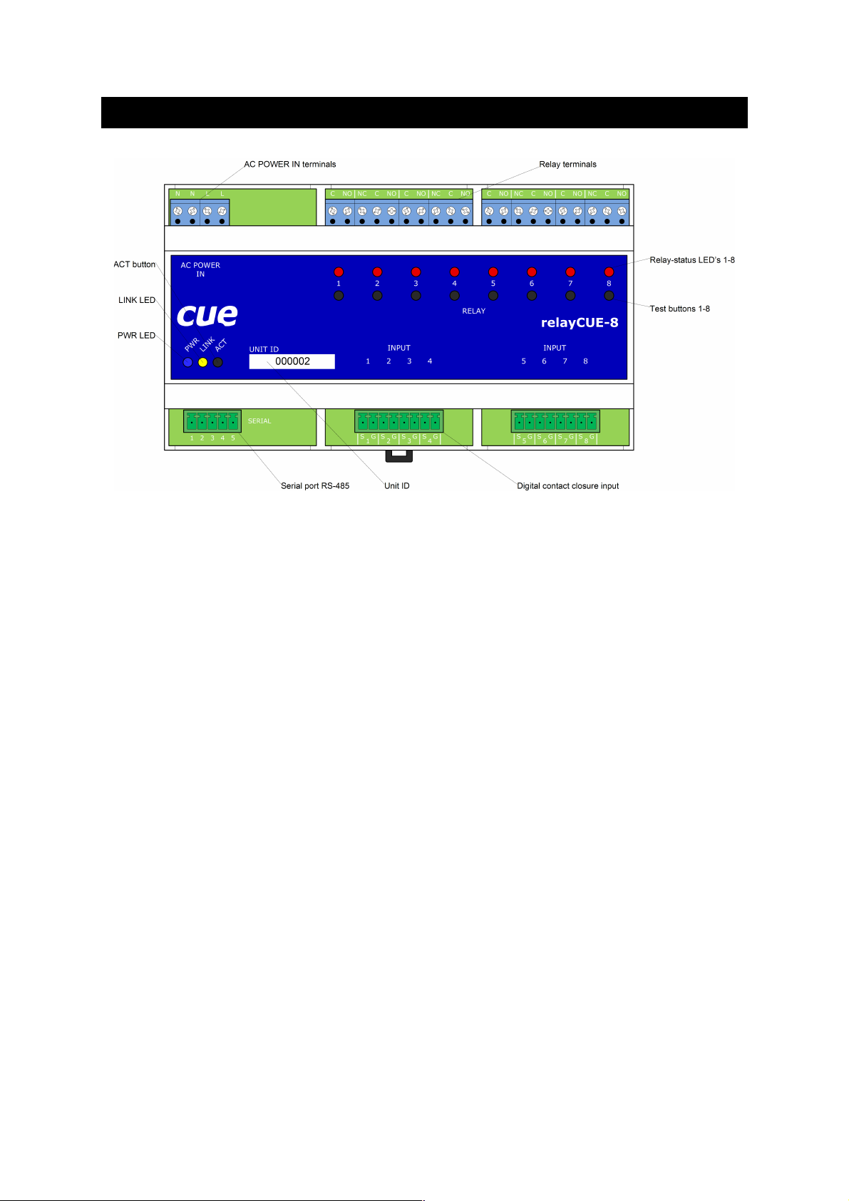
2. Front panel
On the front panel of relayCUE-8, there are the following indicators and buttons (from left to right):
• PWR LED lighted on whenever the unit is powered.
• LINK LED indicates activity on serial port. After power on this unit this LED flashes OK in
“Morse alphabet” - if unit power on test has not recognized any problems and the unit is ready
to work. If power on diagnostic recognizes some kind of internal failure, this LED starts flashing
regularly.
• Relay-status LED's 1-8 - these LEDs are indicating current relay status where relay closed is
indicated by LED light on.
• Test buttons 1-8 - under normal operation, these buttons are logically in parallel to inputs 1-8.
Pressing this button has the same effect as pressing a button connected to the appropriate
input.
• ACT button - when this button is pressed, the relay LED indicators display the Address and
Bank parameters in binary code (for value coding see table below).
Address: on relay LED 1-4 (where LED 1 is LSB and LED 4 is MSB)
Bank: on relay LED 5-8 (where LED 5 is LSB and LED 8 is MSB)
Using this ACT button, you can check the actual setting of both basic system parameters
Address and Bank.
When holding the ACT button, you can also change manually the actual setting of Address
and Bank. By pressing buttons 1-8 (while instant press on ACT) you can toggle the actual
value. The new value must be confirmed by releasing the ACT button and immediate short
press of this button. The new confirmed value displayed on LEDs flashes several times for
a confirmation that the unit accepted the new value.
User Manual relayCUE-8
www.cuesystem.com
Page 5 of 24
Page 6
Note several important points:
• the process of displaying/changing Address and Bank using ACT button has no
influence on current relay status.
• while the ACT button is pressed, inputs 1- 8 remain inactive.
• if you set manually the Address and the Bank on the unit which is working in the
system where currently running project has a relayCUE-8 with its specific UnitID used
in it, then after next Init (i.e. controller reset) the manually set parameters will be lost!
The system in each its Init is renewing all parameters according to the settings in the
currently running project! If the currently running project does not include the unit with
the same UnitID, then the manually set parameters remain valid without any change!
User Manual relayCUE-8
www.cuesystem.com
Page 6 of 24
Page 7
3. Connecting
The enclosure of relayCUE-8 allows simple installation into switchboard on DIN rail.
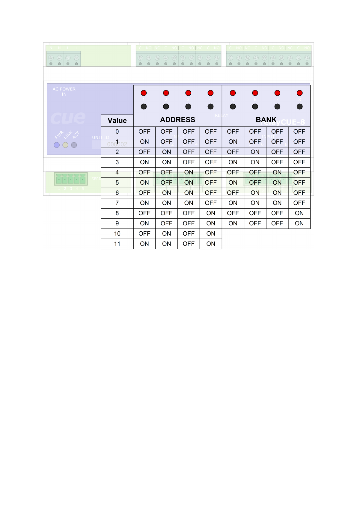
3.1............................Power, input and output connection
Eight digital contact closure inputs are connected via two 8-pin connectors Phoenix 3,5 mm. Every
input has 2 terminals – the first is input signal, the second is input common (ground).
Eight relays are connected via screw-type terminal (up to 1.5 mm2 wire). Four relays have two
terminals C-NO (Common – Normaly Open), 230 V, max. 10 A (resistive load), four relays have three
terminals NC-C-NO (Normaly Close – Common – Normaly Open), 230V, max. 10A (resistive load).
AC Power input is connected via four screw-type terminals (up to 1.5 mm2 wire). Two terminals are L
(Live), two terminals are N (Neutral). A connection of the relays, power and contact closure inputs is
described on the picture below.
All relays are open in this picture.
Important note:
The relay contacts in relayCUE-8 are constructed for resistive load up to 230V/10A. If these
relays are used for the switching of inductive (or capacitive) loads, voltage or power peaks can
occur, which may exceed these parameters even if the load has the stated take-off lower than
230V/10A. We therefore do not recommend using relayCUE-8 for switching inductive or
capacitive loads with take-off higher than 400W.
If you need to switch higher loads, use contactors. Unlike relays, contactors are designed with
features to control and suppress the arc produced when interrupting inductive load currents.
You can then use the relay of the relayCUE-8 unit to control the coil of this contactor.
User Manual relayCUE-8
www.cuesystem.com
Page 7 of 24
Page 8
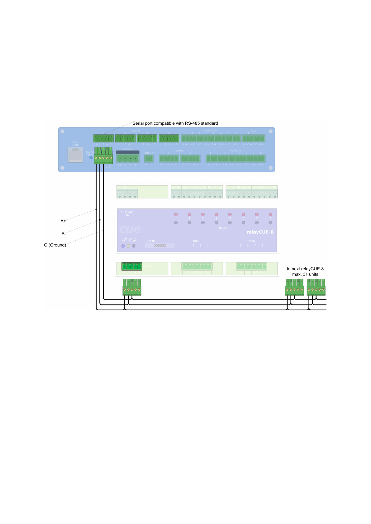
3.2...............................................RS-485 port connection
The relayCUE-8 control port is compatible with RS-485 standard and so it is to be installed on
controller serial ports which are compatible with this standard (i.e. for example on ipCUE-alpha
controller the serial channels S3-S6) or the RS-232/RS-485 converter must be used. Serial port
RS-485 is connected via 5-pin connector Phoenix 3,5 mm.
A typical connection of RS-485 port is shown in the following picture:
User Manual relayCUE-8
www.cuesystem.com
Page 8 of 24
Page 9

relayCUE-8 can also be connected via supplied cable CA0183 and PEbus cable adapter GP0045, see
picture below. Other “Power Express”(PEX) units can also be connected to this bus (see Important
Note below).
For connection of cable CA0183, see Appendix B.
Note:
Max. 31 units (relayCUE-8 or any PEX unit) can be connected to one serial port on ipCUE compatible
with RS-485 standard.
Important Note:
If relayCUE-8 and PEX units are to be combined on the same bus, the PEX units must be
installed and programmed using their serial drivers on serial port like any other serial
controlled equipments (similar way like the relayCUE-8) and not by using “Insert Local Panels
and Interfaces” wizard!
User Manual relayCUE-8
www.cuesystem.com
Page 9 of 24
Page 10

3.3...............................................RS-232 port connection
The controller ports capable only of RS-232 operation (like S1-S2 on ipCUE-alpha) can also be used,
but RS-232/RS-485 converter like unit PEC25 must be used there. For simple connection to PEC25,
the PEbus cable adapter (GP0045) is enclosed in the packing. Power for RS-232/RS-485 converter
PEC25 is on pin 5 of serial connector of relayCUE-8. Other “Power Express” (PEX) units can also be
connected to this bus (see Important Note below).
Note:
Max. 127 units (relayCUE-8 or any PEX unit) can be connected to PEbus port on PEC25.
Important Note:
If relayCUE-8 and PEX units are to be combined on the same bus, the PEX units must be
installed and programmed using their serial drivers on serial port like any other serial
controlled equipments (similar way like the relayCUE-8) and not by using “Insert Local Panels
and Interfaces” wizard!
User Manual relayCUE-8
www.cuesystem.com
Page 10 of 24
Page 11

3.4.........................................IR/SERIAL port connection
In some installation where the proper serial ports are not available and where there is no need to use
the status-reading commands, it is possible to control relayCUE-8 from IR/SERIAL one way
communication port on ipCUE.
The cable for connection to ipCUE IR/SERIAL port needs two wire connections, see picture below:
Please pay attention to the following notes when using this type of installation:
1. cable for this connection is : pin 1 on IR/SERIAL connector on ipCUE is connected to pin 2+3
on SERIAL port connector on relayCUE-8 and pin 2 on IR/SERIAL connector on ipCUE is
connected to pin 1 on SERIAL port connector on relayCUE-8.
2. only one relayCUE-8 unit can be driven from one IR/SERIAL port!
3. commands for reading relay or input statuses have no effect !
User Manual relayCUE-8
www.cuesystem.com
Page 11 of 24
Page 12

4. Configuration
4.1................................Inserting relayCUE-8 into project
To insert relayCUE-8 into your project, proceed as if inserting standard serial controlled equipment.
Choose the serial port and insert the relayCUE-8 driver from library.
If the driver is missing in your library, download the latest relayCUE-8 driver in *.CSE file from our web
and import the driver into your library.
User Manual relayCUE-8
www.cuesystem.com
Page 12 of 24
Page 13

4.2.....................................Setting relayCUE-8 properties
After the relayCUE-8 has been properly inserted into your project, its properties must be set. Select
relayCUE-8 in your project and click on the tab “Properties” in the right window.
User Manual relayCUE-8
www.cuesystem.com
Page 13 of 24
Page 14

The properties are displayed in alphabetical order. The property value can be changed by selecting the
property and then pressing button “Edit Property”. For example when selecting Address, then “Edit
Property” box appears as the one below:
The system properties in the list are Address, Bank and UnitID
The functional properties are Filter, Long Press, RelayX Function, RelayX Paired Channel and RelayX
Time.
UnitID
The UnitID is a unique number which can be seen on the front panel of each relayCUE-8.
See picture bellow - the UnitID there is 000002
Note:
The UnitID allows the system to set the basic communication parameters to the unit : Address and
Bank. All the remaining communication is then done by using these parameters.
Bank and Address
There can be 10 Banks assigned by Bank number. The Bank number is value in range 0...9. In each
Bank there can be relayCUE-8 units - each of them with different unit Address. The Address can be set
to value in range 0..11. Default Address and Bank is 0.
User Manual relayCUE-8
www.cuesystem.com
Page 14 of 24
1 2 3 4 5 6 7 8
PWR
L
I
N
K
A
C
T
AC POWER
IN
UNIT ID
RELAY
000002
relayCUE-8
1 2 3 4 5 6 7 8
INPUT INPUT
N N L L C NO C NO C NO C NOC NONC C NONCC NONCC NONC
1 2 3 4 5
SERIAL
S G1S G2S G3S G
4
S G5S G6S G7S G
8
Page 15

Filter
Filter is time in range 0.01-0.20 sec. It means minimum time of closing/releasing the input contacts
(pressing the button) for the press to be valid. If input is closed/released for shorter time than set in
Filter property then it has no effect.
Long Press
Long Press is time in range 0.0-0.9 sec. If the time of pressing the button is longer than this value, the
press is interpreted as a long press .
RelayX Function
Function selection for control relay by buttons connected to relayCUE-8 inputs:
0 - no action button on appropriate input is disabled.
1 - coded each press causes the toggle of the relay state (switched on/off).
2 - relay when button is pressed, the output is on, otherwise it is off.
3 - system on when pressed, the relay switches on; it can be switched off only by a
command through serial line.
4 - run a short press switches the relay on for the period of “Time” entered in its
parameter. Long time press switches the relay on only while button is being
held. It is suitable for use in couple with another channel with direction mode
for controlling of AC motors. For function in “run” mode, the property “RelayX
Paired Channel” must be set, which is to work in “direction” mode.
5 -direction it is useful for selecting direction of controlled AC motors. After 200 ms the
couple relay with mode “run” is switched on too. For function in “direction”
mode, the property “RelayX Paired Channel” must be set, which is to work in
“run” mode. Mostly the relays working in this mode must be equipped
with N.C. as well as N.O.! Make sure to assign this function only to these
relays - if so requested! (It means relays 2,4,6 and 8).
6 - delayed off the relay is switched on at once, but it is switched off after delay “Time”.
7 - delayed on the relay is switched off at once but it is switched on after delay “Time”.
8 - run DC short press switch relay on for parameter “Time”. Long time press switches
the relay on only while button is being held. It is suitable for use in couple with
another channel with same mode for controlling DC motors (the paired relay
will be switched off). For function in “run DC” mode, the property “RelayX
Paired Channel” must be set, which is to work in couple also in “runDC” mode.
Mostly the relays working in this mode must be equipped with N.C. as
well as N.O.! Pay attention to assign this function only to these relays - if so
requested! (It means relays 2,4,6 and 8).
9 - pulse the relay is switched on for a short time impulse entered in the parameter
“Time”.
RelayX Paired Channel
This parameter is relevant only for functions where two relays are to work in a pair – i.e. “run”,
“direction” or “runDC”. The number is in range 0-8 where 0 means NO paired really channel and
numbers 1-8 means the number of the paired relay.
Please pay attention to set this parameter correctly where necessary. Check if paired relay properties
are correctly set in each pair. Inappropriate setting can lead to unexpected operations.
RelayX Time
The “Time” parameter - can be set to range time: 00:00:00.01 – 23:59:59.99
User Manual relayCUE-8
www.cuesystem.com
Page 15 of 24
Page 16

5. Programming
When programming, you can proceed as in any other serial controller including drag and drop
operations.
The available command are:
Sub RelayOutputClose (Channel as Byte)
This command closes the relay. The parameter Channel – in range 1..8 means relay number.
Sub RelayOutputOpen (Channel as Byte)
This command opens the relay. The parameter Channel – in range 1..8 means relay number.
Sub RelayOutputToggle (Channel as Byte)
This command toggles the relay. The parameter Channel – in range 1..8 means relay number.
Sub RelayOutputPulse(Channel as Byte , Optional PulseTime As Time=:.4)
This command closes the relay for time PulseTime then the relay is opened.
The parameter Channel – in range 1..8 means relay number.
Pulse Time 0.1 – 999.9 sec.
Function RelayState (Channel as Byte) As Boolean
This function reads the actual state of relay. The state TRUE means relay is closed.
The parameter Channel – in range 1..8 means relay number.
Function InputState (Channel as Byte) As Boolean
This function reads the actual state of input. The state TRUE means input contacts closed.
The parameter Channel – in range 1..8 means input number.
Sub IOState (ByRef InputStatus as String, ByRef RelayStatus as String)
Reads all relay and inputs states “in one shot”and returns the values in Status strings.
Status strings (InputStatus and OutputStatus, 8bytes): N1 N2 N3 N4 N5 N6 N7 N8
The Nx means the status of channel x and the values are:
• FF (hexadecimal) - when channel (input or relay) is closed
• 00 (hexadecimal) - when channel (input or relay) is opened
User Manual relayCUE-8
www.cuesystem.com
Page 16 of 24
Page 17

Sub UnitByUnitIDIdentify (ByRef Status as String)
This command serves mostly for testing and it is mainly to be used in debugging programs in large
installations where many relayCUE-8 units have been used. It helps to identify the particular unit in
installation and allows to read all its parameters.
Whenever this command is executed, and the unit with UnitID is set according to the equipment
properties, the LINK LED on the front panel will flash and so it can be easily identified in the rack. It
also sends back the "Unit State String" which is written into Status string. For the "Unit State String"
details see Appendix A (Unit State String description). The length of Status string is 90 bytes.
User Manual relayCUE-8
www.cuesystem.com
Page 17 of 24
Page 18

6. Exchange of relayCUE-8 in existing installation
There are two ways of replacing the relayCUE-8 unit in the existing installation:
1. The best way of making such exchange is replacing the relayCUE-8 by the new one physically,
and then make change in project programming. As soon as the unit with new UnitID is put in
place of the existing one in the project, the only thing that needs to be done is go the
properties of the exchanged unit and enter the new UnitID there. The project then needs to be
compiled and downloaded to the controller in the system.
2. The exchange described in the previous point is not always possible, for example if project
programming is missing, or if it is not possible to do new compile and download. In these
situations you must know at least the Address and Bank of the replaced unit. If you know these
parameters, you can just replace the unit in the system physically and set the Address and
Bank parameters manually using the buttons on the front panel – as described in chapter
“Front panel description”. After parameters have been set correctly, you must reset the
controller in the system and all parameters will be renewed in this unit according to the settings
in original programming.
To explain how the system works in such situation:
The UnitID of this new relayCUE-8 in the installation is unknown to the currently running
project and so the parameters Address and Bank remain unchanged (as explained above). All
the remaining functions are based only on these Address and Bank parameters, so all the
commands and system settings will be accepted by this new unit in the system, and the unit
will act exactly as the replaced one, without the need of reprogramming.
User Manual relayCUE-8
www.cuesystem.com
Page 18 of 24
Page 19

7. Specifications and Mechanical Drawings
Inputs...................................................8 x digital (potential-free) contact closure input,
............................................................ 2 x 8-pin connector Phoenix 3.5 mm
Outputs................................................4 x potential free relay C-NO, 230 V, max. 10 A (resistive load)
............................................................ 4 x potential free relay NC-C-NO, 230 V, max. 10 A (resistive
............................................................ load)
............................................................ max. 400W per relay for inductive or capacitive load
............................................................ screw-type terminals up to 1.5 mm
2
LED indicators.....................................Power, serial channel activity, status of all relays
Buttons................................................ 8 x test button for power relay control,
............................................................ ACT button for address and bank settings
Insulation strength...............................2.5 kV between power and control circuits
Serial communication..........................RS-485, 5-pin connector Phoenix 3.5 mm
Power supply.......................................230 VAC or 110 VAC, 50/60 Hz, 6 W,
............................................................ screw-type terminals up to 1.5 mm
2
Enclosure............................................Plastic DIN rail compatible enclosure
Dimensions..........................................159 x 90 x 58 mm / 6.2” x 3,5” x 2,3” (9 modules 17.5 mm)
Weight.................................................0.5 kg / 1.1 lb
Operating environment........................Temperature 0° to 60° C
............................................................ Humidity 10% to 90% non-condensing
Supplied accessories...........................Cable CA0183
............................................................ Cable adapter GP0045
All dimensions are in mm.
Important note:
The relay contacts in relayCUE-8 are constructed for resistive load up to 230V/10A. If these
relays are used for the switching of inductive (or capacitive) loads, voltage or power peaks can
occur, which may exceed these parameters even if the load has the stated take-off lower than
230V/10A. We therefore do not recommend using relayCUE-8 for switching inductive or
capacitive loads with take-off higher than 400W.
If you need to switch higher loads, use contactors. Unlike relays, contactors are designed with
features to control and suppress the arc produced when interrupting inductive load currents.
You can then use the relay of the relayCUE-8 unit to control the coil of this contactor.
User Manual relayCUE-8
www.cuesystem.com
Page 19 of 24
Page 20

8. Software and Firmware License
END-USER NOTICE AND LICENSE AGREEMENT FROM CUE, a.s.
NOTICE TO END-USER: CAREFULLY READ THE FOLLOWING LEGAL AGREEMENT (THIS "LICENSE").
INSTALLATION OR USE OF THE ENCLOSED CUE, a.s. SOFTWARE PROGRAMS (COLLECTIVELY,
"SOFTWARE") ON YOUR COMPUTER SYSTEMS OR HARDWARE DEVICES CONSTITUTES YOUR
ACCEPTANCE OF THESE TERMS. IF YOU DO NOT AGREE TO THE TERMS OF THIS LICENSE, PROMPTLY
DELETE THE SOFTWARE FROM YOUR COMPUTER SYSTEMS AND HARDWARE DEVICES, DESTROY ANY
COPIES YOU MADE OF THE SOFTWARE OR ANY INSTALLATION MEDIA OF THE SOFTWARE INCLUDED
WITH YOUR SYSTEM, AND DISPOSE OF ALL WRITTEN MATERIALS IN YOUR POSSESSION REGARDING
THE SOFTWARE.
License Grant: CUE grants to You, as an individual, a license to install and use one (1) copy of the Software on
a single computer at a time; provided, however, that You may make copies of the Software solely for Your
development of applications for CUE hardware and demonstration versions of such applications. Any
applications created with the Software may only be used with Cue hardware. Your license to use the Software is
conditioned upon Your compliance with the terms of this License. A License is required for each end-user of the
Software. A license is required for each installation of the Software. You may make one (1) copy of the Software
for archival purposes only. You may use this Software only in connection with CUE hardware. You must have
acquired the Software directly in connection with the purchase of CUE hardware from CUE or from a CUE
approved reseller for this license to be effective. If You have purchased a Site License, You may complete only
the number of installations specified in the License Agreement accompanying the Software.
Copyright: The Software and software built into CUE hardware ("Firmware") are protected by copyright law and
international treaty provisions. You acknowledge that no title to the intellectual property in the Software and
Firmware is transferred to You. You further acknowledge that title and full ownership rights to the Software and
Firmware will remain the exclusive property of CUE, and You will not acquire any rights to the Software and
Firmware except as expressly set forth in this License. You agree that any copies of the Software will contain the
same proprietary notices which appear on and in the Software.
Prohibited Uses: Without obtaining prior written permission from CUE, You may not (a.) use, copy, modify, alter,
or transfer the Software or documentation except as expressly provided in this License; (b.) translate,
disassemble, decompile, reverse program or otherwise reverse engineer the Software and Firmware; (c.)
sublicense or lease the Software or its documentation (d.) use this Software with any hardware other than
products produced by CUE or in connection with applications being developed for CUE hardware; or (e.) use the
Software in a multi-user, network, or multiple computer environment or in a rental, time sharing or computer
service business. Without prejudice to any other rights, CUE may terminate this License if You fail to comply with
its terms and conditions. In such event, You must immediately destroy all copies of the Software.
No Other Warranties: CUE DOES NOT WARRANT THAT THE SOFTWARE AND FIRMWARE IS ERROR
FREE. CUE DISCLAIMS ALL WARRANTIES WITH RESPECT TO THE SOFTWARE AND FIRMWARE, EITHER
EXPRESS OR IMPLIED, INCLUDING BUT NOT LIMITED TO IMPLIED WARRANTIES OF MERCHANTABILITY,
FITNESS FOR A PARTICULAR PURPOSE AND NONINFRINGEMENT OF THIRD PARTY RIGHTS. SOME
JURISDICTIONS DO NOT ALLOW THE EXCLUSION OF IMPLIED WARRANTIES OR LIMITATIONS OF HOW
LONG AN IMPLIED WARRANTY MAY LAST, OR THE EXCLUSION OF LIMITATION OF INCIDENTAL
DAMAGES, SO THE ABOVE LIMITATIONS OR EXCLUSIONS MAY NOT APPLY TO YOU. THIS WARRANTY
GIVES YOU SPECIFIC LEGAL RIGHTS AND YOU MAY ALSO HAVE OTHER RIGHTS WHICH VARY FROM
JURISDICTION TO JURISDICTION.
No Liability for Consequential Damages: IN NO EVENT SHALL CUE BE LIABLE TO YOU FOR ANY
CONSEQUENTIAL, SPECIAL, INCIDENTAL, OR INDIRECT DAMAGES OF ANY KIND ARISING OUT OF THE
PERFORMANCE OR USE OF THE SOFTWARE, EVEN IF CUE HAS BEEN ADVISED OF THE POSSIBILITY
OF SUCH DAMAGES.
Label on Hardware: Use of this hardware and the software programs controlling this hardware is subject to the
terms of the Software and Hardware License Agreements (the “License Agreements”). You should not use the
software and hardware until you have read the License Agreements. By using the software and hardware, you
signify that you have read the Licenses Agreements and accept their terms. The “License Agreement” is
available at www.cuesystem.com.
Trademark Notice: CUE and the CUE logo are trademarks of CUE, a.s. in the United States and in other
countries.
User Manual relayCUE-8
www.cuesystem.com
Page 20 of 24
Page 21

Appendix A: Unit State String description
“Unit State String" - current status of all parameters of the unit (lenght 90 bytes):
byte 1 'i'
byte 2 - 5 '0335'
byte 6 - 9 UnitID (BCD)
byte 10-11 FW version
byte 12 STX ("/02")
byte 13-14 input state (HEX)
byte 15-16 output state (HEX)
byte 17-18 internal check state (HEX) 01-O.K.
byte 19-20 unit address (HEX)
byte 21-22 unit bank (HEX)
byte 23-24 long press time in 0.1sec (HEX)
byte 25-26 input filter in 0.01sec (HEX)
byte 27-28 paired relay to relay 1 (HEX) 00-no pair.
byte 29-30 input1 mode (HEX) "0-NoAction", "1-Coded", "2-Relay", "3-SystemOn",
"4-Run", "5-Direction", "6-DelayedOff", "7-DelayedOn", "8-RunDC", "9-Pulse"
byte 31-32 paired relay to relay 2 (HEX) 00-no pair.
byte 33-34 input2 mode (HEX) "0-NoAction", "1-Coded", "2-Relay", "3-SystemOn",
"4-Run", "5-Direction", "6-DelayedOff", "7-DelayedOn", "8-RunDC", "9-Pulse"
...............
byte 55-56 paired relay to relay 8 (HEX) 00-no pair.
byte 57-58 input8 mode (HEX) "0-NoAction", "1-Coded", "2-Relay", "3-SystemOn",
"4-Run", "5-Direction", "6-DelayedOff", "7-DelayedOn", "8-RunDC", "9-Pulse"
byte 59-62 relay1 timer value (HEX)
byte 53-66 relay2 timer value (HEX)
...............
byte 87-90 relay8 timer value (HEX)
Status string example:
"i0335000501\0200000100000504000100010001000100010001000100010005000500050005000500
0500050005"
User Manual relayCUE-8
www.cuesystem.com
Page 21 of 24
Page 22

Appendix B: Cable CA0183 connection
Note:
The 4P4C connector (popularly, but incorrectly, called RJ11, RJ10, or RJ9), is the de facto industry
standard for wired telephone handsets. It is mainly used to provide connection from the base of the
telephone to the handset.
User Manual relayCUE-8
www.cuesystem.com
Page 22 of 24
Page 23

Notes
User Manual relayCUE-8
www.cuesystem.com
Page 23 of 24
Page 24

Notes
User Manual relayCUE-8
www.cuesystem.com
Page 24 of 24
 Loading...