

Page 1

User Manual
airCUE-8X10
airCUE-6X10
Version 01
CUE, a.s., K Nouzovu 6, 143 00 Praha 4, Czech Republic
phone: +420 241 091 240
fax: +420 241 432 446
www.cuesystem.com
mail: info@cuesystem.com
Page 2

User Manual airCUE-8X10, airCUE-6X10
UM030_01, 1.6.2007
Copyright © CUE, a.s., Praha, Czech Republic 1990 - 2007.
All rights reserved. Specifications are subject to change without prior notice.
Page 3

1. Table of Contents
1.
Table of Contents........................................................................................................................... 3
2. Introduction....................................................................................................................................4
2.1. Overview.................................................................................................................................................4
2.2. airCUE-8X10 Models & Available Accessories........................................................................................4
2.3. airCUE-6X10 Models & Available Accessories........................................................................................4
2.4. Features..................................................................................................................................................5
2.5. Programming...........................................................................................................................................5
3. Box Contents.................................................................................................................................. 6
4. Specifications................................................................................................................................. 7
5. Physical Description......................................................................................................................8
5.1. Front Panel..............................................................................................................................................8
5.2. Top Panel..............................................................................................................................................10
5.3. Rear Panel ............................................................................................................................................11
5.4. Bottom Panel.........................................................................................................................................12
6. Setup and Using........................................................................................................................... 13
6.1. Switch On / Off......................................................................................................................................13
6.2. Charging................................................................................................................................................13
6.3. PC Connection......................................................................................................................................14
6.4. Access Admin Web Server....................................................................................................................16
6.5. Wireless Communication Settings.........................................................................................................16
6.6. Download User Application ...................................................................................................................17
6.7. On Screen Display ................................................................................................................................18
7. Cleaning the Touch Panel........................................................................................................... 21
8. Factory Default Setting................................................................................................................22
9. Software and Firmware License.................................................................................................23
10. Warranty Conditions....................................................................................................................24
11. CE Declaration of Conformity..................................................................................................... 25
12. FCC................................................................................................................................................26
User Manual airCUE-8X10, airCUE-6X10
www.cuesystem.com
Page 3 of 28
Page 4
2. Introduction
2.1. Overview
The airCUE-8X10 and airCUE-6X10 and are superior touch panels cater to the full integration of lifestyle as
well as work style. It combines functionality such as multimedia integration, lighting automation, security
monitoring, entertainment integration, and meeting & presentation control. Unleashed by Wi-Fi this classical
beauty gives professional presenters and homeowners the wireless freedom that they love. From living room
to garden, boardroom to break-room, anywhere there is wireless LAN, both models put them in control and
keep them connected to the world. The long battery life and quick charger keep them wireless with fewer pit
stops. The active matrix touch screen display offers resolution 800 x 600 pixels (airCUE-8X10) or 640 x 480
pixels (airCUE-6X10) and it produces stunning high color images. Innovative design features like 256 MB of
standard data storage provides a level of capability not available with other similar touch panels. Wired
Ethernet connection provides easy network integration. Fully compatible with CUE controllers, this touch
panel provides the ultimate one-touch solution for meeting rooms, conference rooms, boardrooms and hightech homes. Flexible tabletop or wall installation can be done using four types of acce ssories.
2.2. airCUE-8X10 Models & Available Accessories
Model
Stainless steel
enclosure
airCUE-8X10 - CS0300-001 CS0300-002 CS0300-003 CS0300-004 CS0300-005
airCUE-8X10 Tabletop Docking Station - CS0301-001 CS0301-002 CS0301-003 CS0301-004 CS0301-005
airCUE-8X10 Wall Docking Station - CS0302-001 CS0302-002 CS0302-003 CS0302-004 CS0302-005
airCUE-8X10 Tabletop Stand CS0303-001 - - - - airCUE-8X10 Wall Mounting Adapter CS0304-001 - - - - -
Wooden enclosure,
white birch
Wooden enclosure,
oak
Wooden enclosure,
mahogany
Plastic enclosure,
stardust black
Plastic enclosure,
abrasive white
2.3. airCUE-6X10 Models & Available Accessories
Model
Stainless steel
enclosure
airCUE-6X10 - CS0305-001 CS0305-002 CS0305-003 CS0305-004 CS0305-005
airCUE-6X10 Tabletop Docking Station - CS0306-001 CS0306-002 CS0306-003 CS0306-004 CS0306-005
airCUE-6X10 Wall Docking Station - CS0307-001 CS0307-002 CS0307-003 CS0307-004 CS0307-005
airCUE-6X10 Tabletop Stand CS0308-001 - - - - airCUE-6X10 Wall Mounting Adapter CS0309-001 - - - - -
Wooden enclosure,
white birch
Wooden enclosure,
oak
Wooden enclosure,
mahogany
Plastic enclosure,
stardust black
Plastic enclosure,
abrasive white
User Manual airCUE-8X10, airCUE-6X10
www.cuesystem.com
Page 4 of 28
Page 5
2.4. Features
The main features of the unit are
• Display
o airCUE-8X10: 8.4” active matrix touch screen display 800 x 600 pixels
o airCUE-6X10: 6.4” active matrix touch screen display 640 x 480 pixels
• 802.11b/g Wi-Fi 2-way wireless communication
• Wired Ethernet connection
• Power over Ethernet (PoE) IEEE 802.3af compatible
• Battery charging from Power over Ethernet
• Four programmable buttons
• Web server and Admin Web pages for setup and diagnostics
• Built-in microphone and speaker
• Built-in light and motion sensors
• Internal Li-Ion rechargeable battery pack
• Wireless, wired tabletop and wired wall mounting usage
• Tabletop and wall docking stations for charging
2.5. Programming
The control application for airCUE is programmed using Cue Director programming tools.
User Manual airCUE-8X10, airCUE-6X10
www.cuesystem.com
Page 5 of 28
Page 6

3. Box Contents
Each airCUE comes with
1. Touch panel airCUE-8X10 or airCUE-8X10
2. Stylus
3. Ethernet cable straight-through
4. Ethernet cable crossed-over
5. CUEadapter /30W incl. power cable
6. Cleaning tissue
7. CE Declaration of Conformity, RoHS Declaration
8. Touch Panel Data Sheet
9. Cue System Connector Wiring Sheet
10. CUE Application CD
User Manual airCUE-8X10, airCUE-6X10
www.cuesystem.com
Page 6 of 28
Page 7

4. Specifications
Touch-screen display
Active matrix color LCD
Size and resolution
airCUE-8X10: 8.4” / 213 mm diagonal, 800 x 600 pixels
airCUE-6X10: 6.4” / 162 mm diagonal, 640 x 480 pixels
65 536 colors (High Color)
Aspect ratio 4:3
Resistive membrane touch overlay
Built-in sensors
Light sensor for automatic backlight dimming
Motion sensor for resume from display backlight saver mode
Buttons
Power, Reset / Set factory default, 4x programmable
LED indicators
Power
Blue indicates power on or power down mode
Green indicates external power supply
Red indicates charging of battery pack
Wi-Fi (yellow/green) indicates wireless network
Memory
128 MB RAM
CompactFlash Card min. 256 MB (upgradeable)
Software technologies
Admin Web, XPL Inside, WXL
Audio
Built-in microphone, built-in mono speaker
System communication
10/100 BaseT LAN, RJ-45 connector
Wireless network, IEEE 802.11b/g Wi-Fi 2.4 GHz
Power supply
24 VDC (+/- 20%), 13 W, power jack connector
Power over Ethernet (PoE), IEEE 802.3af compatible
Built-in Li-Ion rechargeable battery pack
Physical
Stainless steel – solid wood or plastic enclosure
Dimensions and weight
airCUE-8X10: 263 x 175 x 25 mm / 10.4” x 6.9” x 1.0”, 1.5 kg / 3.3 lb
airCUE-6X10: 216 x 145 x 25 mm / 8.5” x 5.7” x 1.0”, 1.2 kg / 2.7 lb
Operating environment
Temperature 10° to 40° C
Humidity 10% to 90% non-condensing
User Manual airCUE-8X10, airCUE-6X10
www.cuesystem.com
Page 7 of 28
Page 8
5. Physical Description
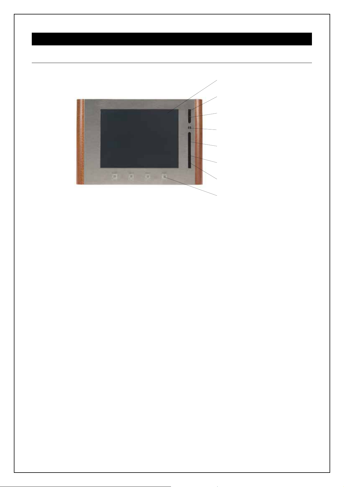
5.1. Front Panel
Touch-screen Display
Power and Charging Indicator
Wi-Fi Indicator
Motion Sensor
Built-in Mono Speaker
Light Sensor
Built-in Microphone
Programmable Buttons
Touch-screen Display
Touch-screen display with active matrix color LCD and resistive membrane touch overlay.
Power and Charging Indicator
Off............................................. The device is off.
Blue On....................................The device is switched on.
Green On ................................. External power supply is connected.
Red On.....................................Battery pack is being charged.
Wi-Fi Indicator
Off............................................. No Wi-Fi connection
Green On ................................. Wi-Fi connected, strong signal
Yellow On ................................ Wi-Fi connected, intermediate or weak signal
Motion Sensor
The Motion Sensor resumes airCUE from Backlight Saver mode.
Built-in Mono Speaker
The built-in mono speaker is prepared for future use. It is not supported by current firmware version.
Light Sensor
The Light Sensor automatically adjusts display backlight according ambient light level.
User Manual airCUE-8X10, airCUE-6X10
www.cuesystem.com
Page 8 of 28
Page 9

Built-in Mono Microphone
The built-in mono speaker is prepared for future use. It is not supported by current firmware version.
Programmable Buttons
The airCUE is equipped with 4 programmable buttons numbered from left. Default button functions are as
follows
• Button 1 – On Screen Display show / hide
• Button 2 – Arrow Left in On Screen Display
• Button 3 – Arrow Right in On Screen Display
• Button 4 – Enter in On Screen Display
User Manual airCUE-8X10, airCUE-6X10
www.cuesystem.com
Page 9 of 28
Page 10

5.2. Top Panel
Stylus
Power Button
Power Supply Connector
(airCUE-6X10 only)
Stylus
Use the stylus to tap or double tap on an application icon or to select items on the menu. The stylus is also
used to type on the On Screen Display. Use of other pointers could damage our screen. When stylus is not
used you can place it in the storage slot located on the top right corner of airCUE.
Power Button
The button Power is used to switch the device between on and power down modes.
Power Supply Connector
This connector allows you to connect airCUE to the external power with the supplied AC adapter. It is used
for charging of the battery without docking station. Not implemented in airCUE-8X10.
User Manual airCUE-8X10, airCUE-6X10
www.cuesystem.com
Page 10 of 28
Page 11

5.3. Rear Panel
Factory Default Button
4x Thread M3 for Accessories
2x Wall Docking Station Fixing
10/100 BaseT LAN incl. PoE Connector
10/100 BaseT LAN Link / Activity
Indicator
Power Supply Connector
2x M3 for Tabletop Stand Fixing
Power Supply Connector
This connector allows you to connect airCUE to the external power with the supplied AC adapter. It is used
for charging of the battery without docking station.
10/100 BaseT LAN incl. PoE Connector
The 10/100 BaseT LAN is a standard network connection 10/100 BaseT LAN using RJ-45 connector. There
is no auto sense, which means it does not recognize straight through cable to cross-over cable. For the
direct PC connection it is necessary to use cross-over cable; for the connection to Ethernet switch straight
through cable. The length of the Ethernet cable connecting touch panel to the network must not exceed 100
meters.
Power over Ethernet (PoE) is fully compatible with IEEE 802.3a standard. PoE integrates data and power on
the same wires. It keeps the structured cabling safe and does not interfere with concurrent network
operation. PoE delivers 48 V of DC power over unshielded twisted-pair wiring for terminals consuming less
than 13 watts of power. PoE needs 802.3a compatible Ethernet switches currently available by most
leading network equipment vendors.
Connector pin out
CUEnet (LAN)
RJ-45
Pin
1
2
3
4
18
5
6
7
8
Signal
TX_D1+ and PoE
TX_D1- and PoE
RX_D2+ and PoE
PoE +/- 48 V
RX-D2- and PoE
PoE Common
Cat5 Cable Color
White / Orange
Orange
White / Green
Blue
White / Blue
Green
White / Brown
Brown
User Manual airCUE-8X10, airCUE-6X10
www.cuesystem.com
Page 11 of 28
Page 12

Factory Default Button
This button carries two functions
1. When pressed shortly (< 2 seconds) the reset of the unit is performed followed by operating system
boot taking approx. 13 seconds.
2. When pressed longer for approx. 5 seconds the factory default function is performed. For factory
default values please see chapter Factory Default Setting.
5.4. Bottom Panel
2x Contact for Docking Station
User Manual airCUE-8X10, airCUE-6X10
www.cuesystem.com
Page 12 of 28
Page 13

6. Setup and Using
6.1. Switch On / Off
The airCUE can be switched on / off by button Power Button located on top panel. The power mode is
indicated by Power and Charging indicator located on the front panel.
Current Mode \ Target Mode Switch On Power Down Mode Switch Off
Switch Off
Indication: no
Switch On
Indication: blue LED on, display backlight on
Power Down Mode
Indication: blue LED on
Power Button
short press
x
Power Button
short press
x x
Power Button
short press
x
Press Power Button until
display backlight goes off
(approx. 2 seconds)
Press Power Button until
blue LED starts to flash
6.2. Charging
External Power Supply
For battery charging touch panel requires power from an external power supply. The standard CUEadapter
/30W is delivered with the unit. Attach the power jack connector of the power supply unit to the power supply
connector located on the bottom panel of airCUE and attach power cable to a power outlet. The green
indicator will light when external power supply is connected and red indicator will light when battery is
charging.
Docking Station
Tabletop Docking Station or Wall Docking Station can be used for charging. Both
docking stations are available and have to be ordered separately.
Docking station is powered by CUEadapter /30W delivered with the airCUE.
Attach the power jack connector of the power supply unit to the power supply
connector located on the bottom panel of docking station and attach power cable
to a power outlet.
Indicators located on the front panel of docking station indicate as follows
• Green indicator will light when external power supply is connected to docking station.
• Red indicator will light when airCUE is placed in docking station correctly.
Power Over Ethernet (PoE)
Touch panel battery is automatically charged if PoE is applied. Be sure charging time is longer against
charging from external power supply.
User Manual airCUE-8X10, airCUE-6X10
www.cuesystem.com
Page 13 of 28
Page 14

6.3. PC Connection
Using LAN Directly to PC
Attach one end of an RJ-45 Ethernet crossed-over cable to the touch panel CUEnet (LAN) port and attach
the other end of the RJ-45 Ethernet cable to your computer.
Ethernet Crossed-Over Cable
This cable can be used to cascade hubs, or for connecting two Ethernet stations back-to-back without a hub.
It works with 10Base-T, 100Base-TX, 100Base-T4 and 1000Base-T. Use a good enough cable, if you are
confused about categories of cables then use Category 5 (enhanced) and you'll be fine even at 1000Base-T.
18
Top
Front
18
To Network Interface Card 1 (NIC 1)
To Network Interface Card 2 (NIC 2)
Computer
RJ45 Male Connector
Name NIC 1 Color NIC 2 Name
TX+ (BI_DA+) 1 White/Orange 3 RX+ (BI_DB+)
TX- (BI_DA-) 2 Orange 6 RX- (BI_DB-)
RX+ (BI_DB+) 3 White/Green 1 TX+ (BI_DA+)
- (BI_DC+) 4 Blue 7 - (BI_DD+)
- (BI_DC-) 5 White/Blue 8 - (BI_DD-)
RX- (BI_DB-) 6 Green 2 TX- (BI_DA-)
- (BI_DD+) 7 White/Brown 4 - (BI_DC+)
- (BI_DD-) 8 Brown 5 - (BI_DC-)
Top
Front
Touch panel
RJ45 Male Connector
18
18
That means that the White/Orange cable connected to NIC 1 pin 1 should go to NIC 2 pin 3 and NIC 1 pin 2
to NIC 2 pin 6 etc.
Notes
1. 1000Base-T names are in parentheses.
2. It's important that each pair is kept as a pair. TX+ & TX- must be in the pair and RX+ & RX- must
together in another pair. Just as the table above shows.
3. While 10Base-T and 100Base-TX only uses 2 pairs, please connect all four since 100Base-T4 and
1000Base-T needs them and save you some future debugging.
4. The colors originate from the numbering and name on NIC 1.
5. The connection is based on IEEE Standard 802.3, 2000 Edition.
User Manual airCUE-8X10, airCUE-6X10
www.cuesystem.com
Page 14 of 28
Page 15

Using LAN Network
Attach one end of an RJ-45 Ethernet straight-through cable to the touch panel CUEnet (LAN) port and
attach the other end of the RJ-45 Ethernet cable to your computer.
Windows XP Local Area Connection Settings
Steps are
1. Start Windows XP.
2. Click Start, then click Control Panel choose the option to switch to Classic View.
3. Double-click Network Connections, select the Local Area Connection and then right-click and select
Properties.
4. Select Internet Protocol (TCP/IP) and click Properties button.
User Manual airCUE-8X10, airCUE-6X10
www.cuesystem.com
Page 15 of 28
Page 16

5. Select Use the following IP address option. Set IP address to 192.168.1.1 (or other address different
from 192.168.1.127) and Subnet mask to 255.255.255.0. Leave other options unchanged and click
OK.
6.4. Access Admin Web Server
Run the Internet browser on your PC and type in the touch panel factory default IP address 192.168.1.128.
The Admin login web page will be displayed. The password is set to default.
6.5. Wireless Communication Settings
Please use Admin Web for Wi-Fi settings.
Note:
In case of troubles please see application note Configuration of More Overlapping WiFi Networks,
which is stored on delivered CUE Application CD or can be downloaded from www.cuesystem.com
Support / Downloads / Application Notes.
, section
User Manual airCUE-8X10, airCUE-6X10
www.cuesystem.com
Page 16 of 28
Page 17

6.6. Download User Application
Overview
User control application is dedicated to control and it is programmed by Cue Director programming tools. It is
composed of elements for AV, lighting, heating, and air conditioning control etc. based on the actual
application.
Using Cue Director XPL
Steps are
1. Connect touch panel to your computer as described in chapter PC Connection.
2. Switch on the touch panel.
3. Run Cue Director XPL.
4. Open Cue System Workspace (CSW) file with Cue Director XPL. It’s necessary to have appropriated
touch panel properly inserted and configured.
5. Right-click on airCUE-xxx Layout and select “Download layout...”.
Using Admin Web
Steps are
1. Connect touch panel to your computer as described in chapter PC Connection.
2. Switch on the touch panel.
3. Run Cue Director XPL.
4. Open Cue System Workspace (CSW) file with Cue Director XPL. It’s necessary to have appropriated
touch panel properly inserted and configured.
5. Right-click on airCUE-xxx Layout and select “Export to WDF file...” and type name of exported file.
6. Start your web browser and open airCUE web pages (for default IP settings open
http://192.168.1.128
7. Go to Application page, browse your WDF file and upload it (see more in section Settings –
Applications page).
page).
User Manual airCUE-8X10, airCUE-6X10
www.cuesystem.com
Page 17 of 28
Page 18

6.7. On Screen Display
Access
On Screen Display is activated by front panel left most button.
Startup Menu
The Startup Menu is activated if no application is
running.
Run downloaded application by button Application.
Launch On Screen Display by button On Screen
Display.
Screen
Backlight Saver will switch off automatically the display
backlight off to conserve battery power and fluorescent
tubes lifetime.
Power Down mode will be reached automatically if
enabled. By decreasing time you can set disabled.
LCD Backlight sets display backlight level.
If Adaptive Brightness is switched to Yes the Light
Sensor automatically adjusts display backlight
according ambient light level.
If Motion Sensor is switched to Yes the Motion Sensor resumes airCUE from Backlight Saver mode
automatically.
User Manual airCUE-8X10, airCUE-6X10
www.cuesystem.com
Page 18 of 28
Page 19

Status
This page shows current status of the touch panel.
IP Settings
This page is used for setting the communication
parameters for your touch panel. The airCUE uses
standard internet protocol (IP) communication
parameters. Certain parameters can be reset by the
user. On start up, this page will display current IP
address. Carefully note this addressing information
(and any changes you elect to make to the IP address,
subnet mask, or default gateway). This information
must be entered into the CUE System Director®
program written for your specific application. For
control systems with more than one unit, a unique IP
address must be given to each CUE device.
For setting please select appropriate field and use numeric keypad. Be sure to click the Apply button for any
changes to the IP settings to become effective.
Note:
The Ethernet connector has to be plugged in prior switching from Wi-Fi to LAN.
Applications
This screen is used for selection; start and stop of
uploaded applications (touch panel layouts). All
uploaded applications are listed on this page.
A “running flag” denotes the active application. The
running application can be stopped via the Stop
button.
Files are uploaded from a personal computer to the
touch panel using CUE System Director software or
using Admin Web.
User Manual airCUE-8X10, airCUE-6X10
www.cuesystem.com
Page 19 of 28
Page 20

Calibration
Battery
Use this page for calibration. We recommend use
stylus.
This page shows current battery status and it’s
charging modes. The type of external power source is
indicated too.
Exit
Closes the On Screen Display.
User Manual airCUE-8X10, airCUE-6X10
www.cuesystem.com
Page 20 of 28
Page 21

7. Cleaning the Touch Panel
You should clean the touch panel screen overlay after each day’s use.
Materials required are
1. Two clean, soft texture cloths (cotton).
2. Spray bottle of cleaning solution without alcohol (window cleaner).
3. Stainless steel parts should be cleaned using a special cleaning solution, for example 3M
Stainless Steel Cleaner & Polish, SS9100 2648 3.
Steps are
1. Turn the touch panel off.
2. Spray a small amount of the cleaning solution onto one of the cloths.
3. Clean the touch panel overlay with the damp cloth.
4. Wipe the touch panel overlay with the dry cloth.
User Manual airCUE-8X10, airCUE-6X10
www.cuesystem.com
Page 21 of 28
Page 22

8. Factory Default Setting
The airCUE is configured as follows
Identification
Name......................Empty
Internet Clock.......................Empty
Date and Time
Time zone............... GMT + 0
Date and time .........Unchanged
IP Connection
Host name ..............Empty
IP address...............192.168.1.128
Subnet mask........... 255.255.255.0
Default gateway......Empty
DNS........................Empty
Applications .........................Unchanged, stopped
Firmware..............................Unchanged
Password............................. Set to empty
Other settings are cleared (see Admin web).
Saved applications and files are not deleted.
User Manual airCUE-8X10, airCUE-6X10
www.cuesystem.com
Page 22 of 28
Page 23

9. Software and Firmware License
END-USER NOTICE AND LICENSE AGREEMENT FROM CUE, a.s.
NOTICE TO END-USER: CAREFULLY READ THE FOLLOWING LEGAL AGREEMENT (THIS "LICENSE").
INSTALLATION OR USE OF THE ENCLOSED CUE, a.s. SOFTWARE PROGRAMS (COLLECTIVELY, "SOFTWARE")
ON YOUR COMPUTER SYSTEMS OR HARDWARE DEVICES CONSTITUTES YOUR ACCEPTANCE OF THESE
TERMS. IF YOU DO NOT AGREE TO THE TERMS OF THIS LICENSE, PROMPTLY DELETE THE SOFTWARE FROM
YOUR COMPUTER SYSTEMS AND HARDWARE DEVICES, DESTROY ANY COPIES YOU MADE OF THE
SOFTWARE OR ANY INSTALLATION MEDIA OF THE SOFTWARE INCLUDED WITH YOUR SYSTEM, AND
DISPOSE OF ALL WRITTEN MATERIALS IN YOUR POSSESSION REGARDING THE SOFTWARE.
License Grant: CUE grants to You, as an individual, a license to install and use one (1) copy of the Software on a sing le
computer at a time; provided, however, that You may make copies of the Software solely for Your development of
applications for CUE hardware and demonstration versions of such applications. Any applications created with the
Software may only be used with Cue hardware. Your license to use the Software is conditioned upon Your compliance
with the terms of this License. A License is required for each end-user of the Software. A license is required for each
installation of the Software. You may make one (1) copy of the Software for archival purposes only. You may use this
Software only in connection with CUE hardware. You must have acquired the Software directly in connection with the
purchase of CUE hardware from CUE or from a CUE approved reseller for this license to be effective. If You have
purchased a Site License, You may complete only the number of installations spec ified in the License Agreement
accompanying the Software.
Copyright: The Software and software built into CUE hardware ("Firmware") are protected by copyright law and
international treaty provisions. You acknowledge that no title to the intellectual pr operty in the Software and Firm ware is
transferred to You. You further acknowledge that title and full o wnership rights to the Soft ware and Firmware will remain
the exclusive property of CUE, and You will not acquir e any right s to the Software and Firm ware except as expressly set
forth in this License. You agree that any copies of the Software will contain the same proprietary notices which appear on
and in the Software.
Prohibited Uses: Without obtaining prior written permission from CUE, You may not (a.) use, copy, modify, alter, or
transfer the Software or documentation except as expressly provided in this License; (b.) translate, disassemble,
decompile, reverse program or otherwise reverse engineer the Software and Firmware; (c.) sublicense or lease the
Software or its documentation (d.) use this Software with any hardware other than products produced by CUE or in
connection with applications being developed for CUE hardware; or (e.) use the Software in a multi-user, network, or
multiple computer environment or in a rental, time sharing or computer service business. Without prejudice to any other
rights, CUE may terminate this License if You fail to comply with its terms and conditions. In such event, You must
immediately destroy all copies of the Software.
No Other Warranties: CUE DOES NOT WARRANT THAT THE SOFTWARE AND FIRMWARE IS ERROR FREE. CUE
DISCLAIMS ALL WARRANTIES WITH RESPECT TO THE SOFTWARE AND FIRMWARE, EITHER EXPRESS OR
IMPLIED, INCLUDING BUT NOT LIMITED TO IMPLIED WARRANTIES OF MERCHANTABILITY, FITNESS FOR A
PARTICULAR PURPOSE AND NONINFRINGEMENT OF THIRD PARTY RIGHTS. SOME JURISDICTIONS DO NOT
ALLOW THE EXCLUSION OF IMPLIED WARRANTIES OR LIMITATIONS OF HOW LONG AN IMPLIED WARRANTY
MAY LAST, OR THE EXCLUSION OF LIMITATION OF INCIDENTAL DAMAGES, SO THE ABOVE LIMITATIONS OR
EXCLUSIONS MAY NOT APPLY TO YOU. THIS WARRANTY GIVES YOU SPECIFIC LEGAL RIGHTS AND YOU MAY
ALSO HAVE OTHER RIGHTS WHICH VARY FROM JURISDICTION TO JURISDICTION.
No Liability for Consequential Damages: IN NO EVENT SHALL CUE BE LIABLE TO YOU FOR ANY
CONSEQUENTIAL, SPECIAL, INCIDENTAL, OR INDIRECT DAMAGES OF ANY KIND ARISING OUT OF THE
PERFORMANCE OR USE OF THE SOFTWARE, EVEN IF CUE HAS BEEN ADVISED OF THE POSSIBILITY OF
SUCH DAMAGES.
Label on Hardware: Use of this hardware and the software programs controlling this hardware is subject to the terms of
the Software and Hardware License Agreements (the “License Agreements”). You should not use the software and
hardware until you have read the License Agreements. By using the software and hardware, you signify that you have
read the Licenses Agreements and accept their terms. The “License Agreement” is available at www.cuesystem.com.
Trademark Notice: CUE and the CUE logo are trademarks of CUE, a.s. in the United States and in other countries.
User Manual airCUE-8X10, airCUE-6X10
www.cuesystem.com
Page 23 of 28
Page 24

10. Warranty Conditions
Warranty Duration
CUE, a.s. provides warranty for all CUE products for a period of 3 years from the day of purchase. The provided warranty for touch
screens is 2 years from the day of purchase. CUE accepts reclamation of 5 not properly working dots and more (2 dot s join – 1 c ounts).
The warranty provided for rechargeable accumulators is 6 months from the day of purchase
Liability
CUE is not liable for any consequential damage caused by CUE products including any loss of profits, incidental or consequential
damages or any claims made by a third parties.
General Warranty Terms
a) CUE warrants that its products are without defects in material and are fully functional for the duration of the warranty.
b) Warranty repairs are free of charge. The customer will send the damaged device to CUE at his cost.
c) All warranty repairs and after warranty services are made at CUE premises. It is strictly prohibited to repair CUE products or
to change any accessory parts, except those parts with limited service life. CUE is not liable for consumables or parts with
limited service life (lamps, batteries etc.)
d) The warranty further does not apply to the following cases
• Damages caused by operating the system not according to the conditions defined in user manual or instruction
(wrong power supply voltage, operation outside deferred temperature range, operation in humid environment and
mechanical damages).
• Damages caused by faulty service, maintenance, connection, and use of other than original connection cable.
• Damage caused by agencies i.e. incidental or unpredictable impacts (fire, earthquake, flood, thunder, strong electric
induction, water, strong wind, theft, vandalism etc.)
After Warranty Services
a) All warranty repairs are normally on a ‘back to base’ basis, as defined in 3 c)
b) All out warranty repair costs will be fully charged to the customer.
c) In cases where our staff are called out to assist, cost of transport and time will be at customer cost
User Manual airCUE-8X10, airCUE-6X10
www.cuesystem.com
Page 24 of 28
Page 25

11. CE Declaration of Conformity
CE Declaration of Conformity
We, the producer CUE, a.s., K Nouzovu 6, Praha 4, Czech Republic
acknowledge our sole responsibility, that the product including accessories
Kind of equipment: Remote Control System
Type designation
(in alphabetical order)
Product Name
airCUE-6X10 CS0300-001 to CS0300-005 PET10 5 CS0245-1, CS0245-2
airCUE-6X10 Tabletop Docking Station CS0301-001 to CS0301-005 powerAUX CS0016
airCUE-6X10 Tabletop Stand CS0303-001 rfbaseCUE CS0171-4, CS0171-8, CS0171-9
airCUE-6X10 Wall Docking Station CS0302-001 to CS0302-005 rfCU E 99 CS0170-*4A, CS0170-*8A, CS0170-*9A
airCUE-6X10 Wall Mounting Adapter CS0304-001 Rx Ext CS0319.401
airCUE-8X10 CS0305-001 to CS0305-005 Rx1 DIN /Data Receiver CS0318.401
airCUE-8X10 Tabletop Docking Station CS0306-001 to CS0306-005 sbiCUE-DMX CS0201
airCUE-8X10 Tabletop Stand CS0308-001 sensorCUE CS0265
airCUE-8X10 Wall Docking Station CS0307-001 to CS0307-005 smartCUE CS0008-R, CS0008-M
airCUE-8X10 Wall Mounting Adapter CS0309-001 soundCUE CS0009
airCUE-XM8 CS0254-W, CS0254-O, CS0254-M touchCUE-L CS0236
airCUE-XM8 Docking Station CS0260-W, CS0260-O, CS0260-M touchCUE-L /b CS0238
analogCUE CS0004 touchCUE-L /b Back Box CS0238-MB
auxCUE CS0005 touchCUE-L /b Rack Moun t Pan e l CS0238-MR
CUEadapter /30W CS0292-001 to CS0292-003 to u chCUE-LV CS0236-V
CUEadapter /65W CS0293-001 to CS0293-003 to u chCUE-LV /b CS0238-V
CUEwire Converter 232/422/485 CS0233 touchCUE-LV 99 CS0234-W-V, , S0234-O-V, CS0234-M-V
eCUE CS0173 touchCUE-M CS0237
inputCUE CS0191 touchCUE-M /b CS0239
ipCUE-alpha CS0251 touchCUE-M /b Back B o x CS0239-MB
ipCUE-beta CS0252 touchCUE -M /b Rack Mount Panel CS0239-MR
ipCUE-delta CS0267 touchCUE-MV CS0237-V
ipCUE-epsilon CS0268 touchCUE-MV /b CS0239-V
ipCUE-gamma CS0253 touchCUE-MV 9 9 CS0235-W-V, CS0235-O-V, CS0235-M-V
ipCUE Rack Mounting Kit CS0251-MR touchCUE-S CS0247
IR Adapter /i
irCUE 99 CS0149-WA, CS0149-OA, CS 01 49 - MA touchCUE-S / b Back Box CS0241-MB
irCUE Receiver 485 CS0169-C touch CUE-S /b Rack Mount Panel CS0241-MR
keyboardCUE-S CS0174-W, CS0174-O, CS0174-M touchCUE-S 99 CS0248-W, CS0248-O, CS0248-M
keyboardCUE 99 CS0145-W, CS0145-O, CS0145-M touchCUE-SRF CS0188-4, CS0188-8, CS0188-9
keypadCUE-1G CS0221 touchC UE-SX /b CS0266
keypadCUE-2G CS0222 touchCUE-SX /b Back Box CS0266-MB
keypadCUE-3G CS0223 touchCUE-S X /b Rack Mount Panel CS0266-MR
monitorCU E CS0203-W, CS0203-O, CS0203-M touchCUE-V /i CS0190
Opto-Input Adapter /i CS0257 touchCUE-XL V 99 CS0261-W-V, CS0261-O-V, CS0261-M-V
PEA208 CS0225-1, CS0225-2 Tx Cr oss 4 CS0317.401
PEC25 CS0163 Tx Element 2 CS0312.401 to CS0312 .424
PED108 CS0164-1, CS0164-2 Tx Element 4 CS0313.401 to CS0313.424
PED202 CS0165-1, CS0165-2 Tx Key CS0316.401
PEF150 CS0249-1, CS0249-2 Tx Pocket 1 CS0314.401
PEF200 CS0166-1, CS0166-2 Tx Pocket 4 CS0315.401
PER610 CS0167-1, CS0167-2 Tx Time 2 CS0310.401 to CS0310.434
PES03 CS0168 Tx Time 4 CS0311.401 to CS0311.434
PET102 CS0244-1, CS0244-2 Universal Ser ial Cable Adapter CS0271
Product Code
CS0256 to
Product Name
uchCUE-S /b CS0241
Product Code
in accordance with EMC Directive 89/33 6/EEC,
is in compliance with the following norms or documents:
EN50082-1 (IEC801-2), IEC65(CO)39, DI N VDE 0839 part 82-1, DIN VDE 0843 part 4, IEC801-4, EN50081-1, EN55022 class B, DIN VDE
0839 part 81-1, EN55014, EN55011.
28.5.2007
Jaroslav Dibitanzl
Member of Board of Directors
User Manual airCUE-8X10, airCUE-6X10
www.cuesystem.com
Page 25 of 28
Page 26

12. FCC
Caution
Changes or modifications to this unit not expressly approved by the party responsible for compliance could void the user's authorit y to
operate the equipment.
Note
This equipment has been tested and found to comply with the limits for a Class B digital device, pursuant to Part 15 of the FCC Rules.
These limits are designed to provide reasonable protection against harmful interference in a residential installation. This equipment
generates, uses and can radiate radio frequency energy and, if not installed and used in accordance with the instructions, may cause
harmful interference to radio communications. However, there is no guarantee that interference will not occur in a particular installation.
If this equipment does cause harmful interference to radio or television reception, which can be determined by turning the equipment off
and on, the user is encouraged to try to correct the interference by one or more of the following measures:
• Reorient or relocate the receiving antenna.
• Increase the separation between the equipment and receiver.
• Connect the equipment into an outlet on a circuit different from that to which the receiver is connected.
• Consult the dealer or an experienced radio / TV technician for help.
User Manual airCUE-8X10, airCUE-6X10
www.cuesystem.com
Page 26 of 28
Page 27

Notes
User Manual airCUE-8X10, airCUE-6X10
www.cuesystem.com
Page 27 of 28
Page 28

Notes
User Manual airCUE-8X10, airCUE-6X10
www.cuesystem.com
Page 28 of 28
 Loading...